US10996678B2 - Obstacle avoidance method and system for robot and robot using the same - Google Patents
Obstacle avoidance method and system for robot and robot using the same Download PDFInfo
- Publication number
- US10996678B2 US10996678B2 US16/236,524 US201816236524A US10996678B2 US 10996678 B2 US10996678 B2 US 10996678B2 US 201816236524 A US201816236524 A US 201816236524A US 10996678 B2 US10996678 B2 US 10996678B2
- Authority
- US
- United States
- Prior art keywords
- detection
- data
- robot
- detection data
- value
- Prior art date
- Legal status (The legal status is an assumption and is not a legal conclusion. Google has not performed a legal analysis and makes no representation as to the accuracy of the status listed.)
- Active, expires
Links
Images


Classifications
-
- G—PHYSICS
- G05—CONTROLLING; REGULATING
- G05D—SYSTEMS FOR CONTROLLING OR REGULATING NON-ELECTRIC VARIABLES
- G05D1/00—Control of position, course, altitude or attitude of land, water, air or space vehicles, e.g. using automatic pilots
- G05D1/02—Control of position or course in two dimensions
- G05D1/021—Control of position or course in two dimensions specially adapted to land vehicles
- G05D1/0212—Control of position or course in two dimensions specially adapted to land vehicles with means for defining a desired trajectory
- G05D1/0214—Control of position or course in two dimensions specially adapted to land vehicles with means for defining a desired trajectory in accordance with safety or protection criteria, e.g. avoiding hazardous areas
-
- G—PHYSICS
- G01—MEASURING; TESTING
- G01S—RADIO DIRECTION-FINDING; RADIO NAVIGATION; DETERMINING DISTANCE OR VELOCITY BY USE OF RADIO WAVES; LOCATING OR PRESENCE-DETECTING BY USE OF THE REFLECTION OR RERADIATION OF RADIO WAVES; ANALOGOUS ARRANGEMENTS USING OTHER WAVES
- G01S17/00—Systems using the reflection or reradiation of electromagnetic waves other than radio waves, e.g. lidar systems
- G01S17/88—Lidar systems specially adapted for specific applications
- G01S17/93—Lidar systems specially adapted for specific applications for anti-collision purposes
- G01S17/931—Lidar systems specially adapted for specific applications for anti-collision purposes of land vehicles
-
- G—PHYSICS
- G05—CONTROLLING; REGULATING
- G05D—SYSTEMS FOR CONTROLLING OR REGULATING NON-ELECTRIC VARIABLES
- G05D1/00—Control of position, course, altitude or attitude of land, water, air or space vehicles, e.g. using automatic pilots
- G05D1/02—Control of position or course in two dimensions
- G05D1/021—Control of position or course in two dimensions specially adapted to land vehicles
-
- G—PHYSICS
- G05—CONTROLLING; REGULATING
- G05D—SYSTEMS FOR CONTROLLING OR REGULATING NON-ELECTRIC VARIABLES
- G05D1/00—Control of position, course, altitude or attitude of land, water, air or space vehicles, e.g. using automatic pilots
- G05D1/20—Control system inputs
- G05D1/24—Arrangements for determining position or orientation
- G05D1/242—Means based on the reflection of waves generated by the vehicle
-
- G—PHYSICS
- G05—CONTROLLING; REGULATING
- G05D—SYSTEMS FOR CONTROLLING OR REGULATING NON-ELECTRIC VARIABLES
- G05D1/00—Control of position, course, altitude or attitude of land, water, air or space vehicles, e.g. using automatic pilots
- G05D1/02—Control of position or course in two dimensions
- G05D1/021—Control of position or course in two dimensions specially adapted to land vehicles
- G05D1/0231—Control of position or course in two dimensions specially adapted to land vehicles using optical position detecting means
- G05D1/0238—Control of position or course in two dimensions specially adapted to land vehicles using optical position detecting means using obstacle or wall sensors
- G05D1/024—Control of position or course in two dimensions specially adapted to land vehicles using optical position detecting means using obstacle or wall sensors in combination with a laser
-
- G—PHYSICS
- G05—CONTROLLING; REGULATING
- G05D—SYSTEMS FOR CONTROLLING OR REGULATING NON-ELECTRIC VARIABLES
- G05D1/00—Control of position, course, altitude or attitude of land, water, air or space vehicles, e.g. using automatic pilots
- G05D1/60—Intended control result
- G05D1/617—Safety or protection, e.g. defining protection zones around obstacles or avoiding hazards
- G05D1/622—Obstacle avoidance
-
- G—PHYSICS
- G05—CONTROLLING; REGULATING
- G05D—SYSTEMS FOR CONTROLLING OR REGULATING NON-ELECTRIC VARIABLES
- G05D1/00—Control of position, course, altitude or attitude of land, water, air or space vehicles, e.g. using automatic pilots
- G05D1/0088—Control of position, course, altitude or attitude of land, water, air or space vehicles, e.g. using automatic pilots characterized by the autonomous decision making process, e.g. artificial intelligence, predefined behaviours
Definitions
- the present disclosure relates to robot technology, and particularly to an obstacle avoidance method and system for a robot as well as a robot using the same.
- the robots with autonomous navigation capability are usually disposed with different types of ranging sensors to detect different kinds of environmental information to ensure that the robot can obtain the obstacle information completely.
- the mixed use of multiple sensors will still cause the robot to have certain detection blind zones.
- the single-line laser sensor can only collect the detection data on the horizontal plane parallel to the movement direction of the robot; the depth sensor has a large detection blind zone while it is used in close distance ranging since it has a smaller vision field, and the transparent object that cannot be effectively imaged cannot be detected; the ultrasonic sensor can detect the transparent objects while only the detection data of a single point can be collected, which has a small measurement range.
- FIG. 1 is a schematic diagram of a robot according to a first embodiment of the present disclosure.
- FIG. 2 is a schematic block diagram of a robot obstacle avoidance system according to a second embodiment of the present disclosure.
- FIG. 3 is a schematic diagram of a robot and a detection plane of its sensors according to a third embodiment of the present disclosure.
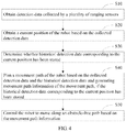
- FIG. 4 is a flow chart of an obstacle avoidance method for a robot according to the third embodiment of present disclosure.
- FIG. 5 is a flow chart of an obstacle avoidance method for a robot according to a fourth embodiment of present disclosure.
- FIG. 6 is a schematic diagram of a projection process according to the fourth embodiment of present disclosure.
- FIG. 7 is a flow chart of an obstacle avoidance method for a robot according to a fifth embodiment of present disclosure.
- FIG. 8 is a flow chart of an obstacle avoidance method for a robot according to a sixth embodiment of present disclosure.
- FIG. 1 is a schematic diagram of a robot according to a first embodiment of the present disclosure.
- a robot 8 is provided, which includes a processor 80 , a memory 81 , a computer program 82 , and a plurality of ranging sensors 83 .
- the computer program 82 is stored in the memory 81 and executable on the processor 80 , for example, an obstacle avoidance program.
- the processor 80 executes the (instructions in) computer program 82
- the functions of each module/unit in the device embodiments for example, the functions of the modules 10 - 50 shown in FIG. 2 are implemented.
- the computer program 82 may be divided into one or more modules/units, and the one or more modules/units are stored in the storage 81 and executed by the processor 80 to realize the present disclosure.
- the one or more modules/units may be a series of computer program instruction sections capable of performing a specific function, and the instruction sections are for describing the execution process of the computer program 82 in the robot 8 .
- computer program 82 can be divided into a detection data obtaining module, a position obtaining module, a determining module, a path planning module, and a movement controlling module.
- the specific function of each module is as follows:
- the detection data obtaining module is configured to obtain detection data collected by the plurality of ranging sensors 83 ;
- the position obtaining module is configured to obtain a current position of the robot based on the collected detection data
- the determining module is configured to determine whether historical detection data corresponding to die current position has been stored
- the path planning module is configured to plan a movement path of the robot based on the collected detection data and the historical detection data and generating movement path information of the movement path, if the historical detection data corresponding to the current position has been stored;
- the movement controlling module is configured to control the robot to move along an obstacle-free path based on the movement path information.
- the robot 8 may include, but is not limited to, a processor 80 and a storage 81 . It can be understood by those skilled in the art that FIG. 1 is merely an example of the robot 8 and docs not constitute a limitation on the robot 8 , and may include more or fewer components than those shown in the figure, or a combination of some components or different components.
- the robot 8 may further include an input/output device, a network access device, a bus, and the like.
- the processor 80 may be a central processing unit (CPU), or be other general purpose processor, a digital signal processor (DSP), an application specific integrated circuit (ASIC), a field-programmable gale array (FPGA), or be other programmable logic device, a discrete gate, a transistor logic device, and a discrete hardware component.
- the general purpose processor may be a microprocessor, or the processor may also be any conventional processor.
- the storage 81 may be an internal storage unit of the robot 8 , for example, a hard disk or a memory of the robot 8 .
- the storage 81 may also be an external storage device of the robot 8 , for example, a plug-in hard disk, a smart media card (SMC), a secure digital (SD) card, flash card, and the like, which is equipped on the robot 8 .
- the storage 81 may further include both an internal storage unit and an external storage device, of the robot 8 .
- the storage 81 is configured to store the computer program 82 and other programs and data required by the robot 8 .
- the storage 81 may also be used to temporarily store data that has been or will be output.
- FIG. 2 is a schematic block diagram of a robot obstacle avoidance system according to a second embodiment of the present disclosure.
- an obstacle avoidance system 7 for a robot is provided, where the robot is disposed with a plurality of ranging sensors.
- the obstacle avoidance system 7 is for performing the method in the above-mentioned method embodiments.
- the obstacle avoidance system 7 is a software system (e.g., a program) executed by a processor of the robot.
- the obstacle avoidance system 7 includes:
- a detection data obtaining module 10 configured to obtain detection data collected by the plurality of ranging sensors
- a position obtaining module 20 configured to obtain a current position of the robot based on the collected detection data
- a determining module 30 configured to determine whether historical detection data corresponding to the current position has been stored
- a path planning module 40 configured to plan a movement path of the robot based on the collected detection data and the historical detection data and generating movement path information of the movement path, if the historical detection data corresponding to the current position has been stored;
- a movement controlling module 50 configured to control the robot to move along an obstacle-free path based on the movement path information.
- the determining module 30 is further configured to determine whether the collected detection data is valid, and the obstacle avoidance system further includes:
- a storage module configured to store the collected detection data as the historical detection data corresponding to the current position (for the next movement of the robot to the current position), if the collected detection data is valid.
- the path planning module 40 is further configured to plan the movement path of the robot based on the collected detection data and generate the movement path information of the movement path, if the historical detection data corresponding to the current position has not been stored.
- the detection data obtaining module 10 is further configured to obtain first detection data of the laser sensor at the current position, and obtain second detection data of the other sensor at the current position, and the obstacle avoidance system further includes:
- a projection module configured to project the second detection data to a detection plane of the laser sensor to obtain projection data of the second detection data on the detection plane, where the first detection data is on the detection plane;
- a coincidence degree determination module configured to determine a coincidence degree of the projection data and the first detection data
- a storage module configured to store the second detection data as the historical detection data corresponding to the current position, if the coincidence degree is 0;
- a spatial distance obtaining module configured to obtain a first spinal distance between the first detection data and the robot and obtaining a second spatial distance between the projection data and the robot, if the coincidence degree is less than a preset threshold
- the storage module is further configured to store the second detection data as the historical detection data corresponding to the current position, if the first spatial distance is larger than the second spatial distance.
- the obstacle avoidance system further includes:
- a discarding module configured to discard the second detection data, if the coincidence degree is larger than or equal to the preset threshold or the first spatial distance is less than or equal to the second spatial distance.
- detection data collected by ranging sensors is obtained first, and a current position of a robot is obtained based on the collected detection data, then based un a stored historical detection data corresponding to the current position and the collected detection data, a movement path of the robot is planned and movement path information is generated, and then the robot is controlled to move along an obstacle-free path based on the movement path information, which is capable of effectively breaking through the limitation of the sensor technology, reducing the detection blind zone, and effectively improving the obstacle avoidance efficiency and the obstacle avoidance success rate of a robot.
- the obstacle avoidance system 7 may be an obstacle avoidance apparatus disposed on the robot, in which the apparatus may include a processor, a memory, and a computer program stored in the memory and executable on the processor.
- the computer program includes the above-mentioned modules in the obstacle avoidance system 7 .
- each of the above-mentioned modules/units may be implemented in the form of hardware (e.g., a circuit), software (e.g., a program), or a combination thereof (e.g., a circuit with a single chip microcomputer).
- FIG. 3 is a schematic diagram of a robot and a detection plane of its sensors according to a third embodiment of the present disclosure. As shown in FIG. 3 , in this embodiment, a robot 100 having autonomous navigation capability is provided, which includes a plurality of ranging sensors.
- the robot refers to any robot having an autonomous navigation capability, which may include a humanoid robot or a non-human robot with any structure, for example, an automatic guided vehicle, a sweeping robot, a robot assistant, or the like.
- FIG. 3 shows that the robot 100 is a robot including a spherical head and a rectangular body.
- the robot may include any type of ranging sensors (sensors for ranging), for example, laser sensor (e.g., laser radar), depth sensor (e.g., depth camera), infrared sensor, ultrasonic sensor (e.g., ultrasonic radar).
- laser sensor e.g., laser radar
- depth sensor e.g., depth camera
- infrared sensor e.g., infrared sensor
- ultrasonic sensor e.g., ultrasonic radar
- FIG. 3 shows that on a body part of the robot 100 , a depth sensor 101 , a laser sensor 102 , and an ultrasonic sensor 103 are disposed in the order from top to bottom.
- the detection area of the depth sensor 101 is a plane area 201 of the object 200 which faces the robot 100 .
- the detection area of the laser sensor 102 is a line 202 of the object 200 which faces the robot 100
- the detection area of the ultrasonic sensor 103 is a point 203 of the object 200 which faces the robot 100 .
- the structure and shape of the robot 100 shown in FIG. 3 is merely exemplary and is for illustrative purposes only, which do not represent the actual structure and shape of the robot.
- the detection blind zone of the robot 100 shown in FIG. 3 is an area of the object 200 which faces the robot 100 and is not covered by the plane area 201 , the line 202 , and the point 203 .
- this embodiment provides an obstacle avoidance method for a robot.
- the method can be applied to the above-mentioned robot 100 , and can be executed by a processor disposed on a robot 100 .
- the processor is communicatively connected to each sensor, so as to obtain the detection data of each sensor.
- the processor also has an internal storage space and/or is connected to a storage (e.g., a memory) for storing the obtained detection data.
- the processor 60 may be a central processing unit (CPU), or be other general purpose processor, a digital signal processor (DSP), an application specific integrated circuit (ASIC), a field-programmable gate array (FPGA), or the other programmable logic device, a discrete gate, a transistor logic device, and a discrete hardware component.
- the general purpose processor may be a microprocessor, or the processor may also be any conventional processor.
- FIG. 4 is a flow chart of an obstacle avoidance method for a robot according to the third embodiment of present disclosure.
- the method is a computer-implemented method executable for a processor, which may be implemented through a robot obstacle avoidance system as shown in FIG. 2 or a robot as shown in FIG. 1 .
- the method can be applied to a robot which is disposed with a plurality of ranging sensors. In other embodiments, the may be further disposed with other types of sensors.
- the method includes the following steps.
- the detection data is collected in real time or at a fixed frequency (i.e., there's a preset time interval between each collection).
- the type of the detection data is determined by the type of the sensor, for example, the detection data collected by the depth sensor is depth data, and the detection data collected by the ultrasonic sensor is ultrasonic data.
- the (currently) collected detection data is the detection data collected by each sensor at the current time.
- the shape and contour of each object in the current environment and the distance between the detected object and the robot can be determined, and the distance and orientation of the robot with respect to each object in the environment at the current time can be determined based on the data, so as to know the position of the robot in the current environment at the current time.
- the valid and accurate detection data is stored as the historical detection data, so that the robot can use in the subsequent movement.
- step S 20 the method further includes:
- the collected detection data storing the collected detection data as the historical detection data corresponding to the current position (for the next movement of the robot to the current position), if the collected detection data is valid.
- the movement path information may include, for example, a route map for the movement path.
- the robot can therefore be helped to plan the movement path in a more accurate manner by combining the valid data which is collected last time, so that the robot can accurately predict the obstacles in the current environment in time to prevent the robot from colliding with the objects in the current environment.
- step S 30 the method further includes:
- the movement path can be directly planned based on the (currently) collected detection data.
- the obstacle-free path is a path for the robot to move in the environment at which the robot locates on the premise that the robot can be kept away front the obstacles in the environment.
- the robot after generating the movement path information, the robot can be controlled to move based on the information while timely and effectively avoiding the obstacles in the current environment.
- detection data collected by ranging sensors is obtained first, and a current position of a robot is obtained based on the collected detection data, then based on a stored historical detection data corresponding to the current position and the collected detection data, a movement path of the robot is planned and movement path information is generated, and then the robot is controlled to move along an obstacle-free path based on the movement path information, which is capable of effectively breaking through the limitation of the sensor technology, reducing the detection blind zone, and effectively improving the obstacle avoidance efficiency and the obstacle avoidance success rate of a robot.
- the robot includes a laser sensor and at least one other sensor.
- the at least one other sensor includes a depth sensor and an ultrasonic sensor.
- the robot may be the robot 100 shown in FIG. 3 .
- FIG. 5 is a flow chart of an obstacle avoidance method for a robot according to a fourth embodiment of present disclosure. As show n in FIG. 5 , based on the robot provided in Embodiment 3, step S 10 in Embodiment 3 includes the following steps.
- the first detection data may be laser ranging data collected by the laser sensor at the current position
- the second detection data may include depth data collected by the depth sensor at the current position and/or ultrasonic sensor data collected by the ultrasonic sensor at the current position.
- the detection plane of the laser sensor is a plane parallel to the movement direction of the robot, and the second detection data (and the laser ranging data) is at the detection plane.
- FIG. 6 is a schematic diagram of a projection process according to the fourth embodiment of present disclosure.
- projection data of the detection data collected by the robot shown in FIG. 3 on the detection plane of the laser sensor is exemplarily shown.
- the projection data of the depth data is a straight line 401 located at the detection plane
- the laser ranging data is a broken line 402 located at the detection plane
- the projection data of the ultrasonic data is a plurality of points 403 located at the detection plane.
- the dotted arrow in FIG. 6 indicates the projection direction.
- the second detection data is projected onto the detection plane where the first detection data is located, thereby eliminating the difference between the first detection data and the second detection data in a direction perpendicular to the movement direction of the robot, and the difference between the first detection data and the second detection data in the detection plane parallel to the movement direction of the robot can be intuitively compared.
- the degree of the coincidence between the projection data and the first detection data can be determined in a convenient manner, for example, referring to FIG. 6 , an overlapping portion of the broken line 401 and the straight line 402 is the overlapping portion of the laser ranging data and the projection data of the depth data.
- the projection data refers to projection data corresponding to the detection data of any other sensor of the robot.
- the robot includes more than one other sensors, it is necessary to respectively determine the coincidence degree of the projection data corresponding to each other sensor and the first detection data.
- the coincidence degree of the projection data of the second detection data and the first detection data is 0, it indicates that all the data collected by the other sensor which corresponds to the second detection data had not been collected by the laser sensor.
- the second detection data needs to be stored as the historical detection data corresponding to the current position, so as to be used when the robot is moved to the current position at the next time. If the coincidence degree is 0, the robot can directly use the first detection data and the second detection data simultaneously in the current movement.
- the preset threshold may be set according to actual needs, for example, may be set to any value between 50% and 100%. If the coincidence degree is less than the preset threshold, it indicates that the other sensor corresponding to the second detection data has collected part of the data which is not collected by the laser sensor. In this case, it is necessary to further determine the validity of the projection data and the first detection data, that is, determine which of the two data is collected by the corresponding sensor closer to the obstacle. The spatial distance between the projection data on the detection plane and the robot as well as the spatial distance between the first detection data and the robot can be obtained, and then the two spatial distances are compared to determine which sensor corresponding to the data is closer to the obstacle.
- the second detection data is needed to be stored as the historical detection data, so as to be used in combination with the first detection data when the robot is at the current position at this time and at next time, thereby planning the movement path.
- step S 306 the method further includes:
- the validity of the detection data collected by other sensor is determined, the valid data is stored while the invalid data is discarded, which is capable of planning the movement path in a reasonable manner based on the valid data and the laser ranging data, thereby improving the obstacle avoidance efficiency and the obstacle avoidance success rate of a robot.
- the storage space can be freed up, thereby improving the data processing speed of the robot.
- FIG. 7 is a flow chart of an obstacle avoidance method for a robot according to a firth embodiment of present disclosure. As shown in FIG. 7 , in this embodiment, step S 303 in Embodiment 4 includes the following steps.
- any alignment maybe adopted to align the projection data with the first detection data, for example, center alignment, left alignment, or right alignment.
- the first detection value and the second detection value may be represented as a horizontal coordinate at the detection plane.
- ⁇ XY Cov ⁇ ( X , Y ) D ⁇ ( X ) ⁇ • ⁇ D ⁇ ( Y ) ;
- X is the first detection value
- Y is the second detection value
- x 1 , x 2 , . . . , x n each is the value of each data point in the first detection data
- y 1 , y 2 , . . . , y m each is the value of each data point in the projection data
- N indicates a natural number
- ⁇ XY is the correlation coefficient
- Cov(X,Y) is a covariance between the first detection value and the second detection value
- D(X) is a variance of the first detection value
- D(Y) is a variance of the second detection value.
- the expected value of the first detection value is the average value of the values of all the data points in the first detected data
- the expected value of the second detection value is the average value of the values of all the data points in the projected data.
- an error is allowed when determining whether the correlation coefficient approaches 1 or not (i.e., whether the correlation coefficient approaches 1 or not can be determined to a tolerance); similarly, an error is also allowed when determining whether the expected value of the first detection value approaches the expected value of the second detection value or not (i.e., whether the expected value of the first detection value approaches the expected value of the second detection value or not can be determined to a tolerance).
- the allowable errors can be respectively defined according to the actual needs and/or the experiences of implementation.
- a method for determining the coincidence degree between the projection data and the first detection data is provided, which is capable of determining the coincidence degree between the projection data and the first detection data accurately and quickly, so that the validity of the projection data can be determined accurately and quickly.
- FIG. 8 is a flow chart of an obstacle avoidance method for a robot according to a sixth embodiment of present disclosure. As shown in FIG. 8 , in this embodiment, step S 305 in Embodiment 4 includes the following steps.
- the amount of the first data points may be determined according to actual needs, and the more the amount of the first data points, the more accurate the calculated first spatial distance.
- the amount of the second data points can be determined according to actual needs, and the more the amount of the second data points, the more accurate the calculated second spatial distance.
- the spatial distances between the first detection data as well as the projection data and the robot may be the distances between the first detection data as well as the projection data and any point of the robot, for example, the geometric center of the robot, any point on the vertical central axis of the robot, or the like.
- a method for determining the spatial distance between the projection data as well as the first detection data and the robot is provided, which is capable of determining the spatial distance between the projection data as well as the first detection data and the robot accurately and quickly, thereby determining the magnitude of the first spatial distance and the second spatial distance accurately and quickly, so that the validity of the projection data can be determined accurately and quickly.
- the division of the above-mentioned functional units and modules is merely an example for illustration.
- the above-mentioned functions may be allocated to be performed by different functional units according to requirements, that is, the internal structure of the device may be divided into different functional units or modules to complete all or part of the above-mentioned functions.
- the functional units and modules in the embodiments may be integrated in one processing unit, or each unit may exist alone physically, or two or more units may be integrated in one unit.
- the above-mentioned integrated unit may be implemented in the form of hardware or in the form of software functional unit.
- each functional unit and module is merely for the convenience of distinguishing each other and are not intended to limit the scope of protection of the present disclosure.
- the specific operation process of the units and modules in the above-mentioned system reference may be made to the corresponding processes in the above-mentioned method embodiments, and are not described herein.
- the disclosed system/robot and method may be implemented in other manners.
- the above-mentioned system/robot embodiment is merely exemplary.
- the division of modules or units is merely a logical functional division, and other division manner may be used in actual implementations, that is, multiple units or components may be combined or be integrated into another system, or some of the features may be ignored or not performed.
- the shown or discussed mutual coupling may be direct coupling or communication connection, and may also be indirect coupling or communication connection through some interfaces, devices or units, and may also be electrical, mechanical or other forms.
- the integrated module/unit When the integrated module/unit is implemented in the form of a software functional unit and is sold or used as an independent product, the integrated module/unit may be stored in a non-transitory computer-readable storage medium. Based on this understanding, all or part of the processes in the method for implementing the above-mentioned embodiments of the present disclosure are implemented, and may also be implemented by instructing relevant hardware through a computer program.
- the computer program may be stored in a non-transitory computer-readable storage medium, which may implement the steps of each of the above-mentioned method embodiments when executed by a processor.
- the computer program includes computer program codes which may be the form of source codes, object codes, executable files, certain intermediate, and the like.
- the computer-readable medium may include any primitive or device capable of carrying the computer program codes, a recording medium, a USB flash drive, a portable hard disk, a magnetic disk, an optical disk, a computer memory, a read-only memory (ROM), a random access memory (RAM), electric carrier signals, telecommunication signals and software distribution media.
- a computer readable medium may be appropriately increased or decreased according to the requirements of legislation and patent practice in the jurisdiction. For example, in some jurisdictions, according to the legislation and patent practice, a computer readable medium does not include electric carrier signals and telecommunication signals.
Landscapes
- Engineering & Computer Science (AREA)
- Physics & Mathematics (AREA)
- Radar, Positioning & Navigation (AREA)
- Remote Sensing (AREA)
- General Physics & Mathematics (AREA)
- Aviation & Aerospace Engineering (AREA)
- Automation & Control Theory (AREA)
- Electromagnetism (AREA)
- Computer Networks & Wireless Communication (AREA)
- Optics & Photonics (AREA)
- Control Of Position, Course, Altitude, Or Attitude Of Moving Bodies (AREA)
- Manipulator (AREA)
Abstract
Description
X=[x 1 ,x 2 , . . . ,x n |n∈N];
Y=[y 1 ,y 2 , . . . ,y m |m∈N];
Claims (14)
X=[x 1 ,x 2 , . . . ,x n |n∈N];
Y=[y 1 ,y 2 , . . . ,y m |m∈N];
X=[x 1 ,x 2 , . . . ,x n |n∈N];
Y=[y 1 ,y 2 , . . . ,y m |m∈N];
Applications Claiming Priority (2)
| Application Number | Priority Date | Filing Date | Title |
|---|---|---|---|
| CN201810863769.4A CN110850859B (en) | 2018-08-01 | 2018-08-01 | A robot and its obstacle avoidance method and obstacle avoidance system |
| CN201810863769.4 | 2018-08-01 |
Publications (2)
| Publication Number | Publication Date |
|---|---|
| US20200042005A1 US20200042005A1 (en) | 2020-02-06 |
| US10996678B2 true US10996678B2 (en) | 2021-05-04 |
Family
ID=69228614
Family Applications (1)
| Application Number | Title | Priority Date | Filing Date |
|---|---|---|---|
| US16/236,524 Active 2039-10-09 US10996678B2 (en) | 2018-08-01 | 2018-12-30 | Obstacle avoidance method and system for robot and robot using the same |
Country Status (2)
| Country | Link |
|---|---|
| US (1) | US10996678B2 (en) |
| CN (1) | CN110850859B (en) |
Cited By (1)
| Publication number | Priority date | Publication date | Assignee | Title |
|---|---|---|---|---|
| US20230229168A1 (en) * | 2020-06-02 | 2023-07-20 | BSH Hausgeräte GmbH | Method for bypassing impassable objects by a robot |
Families Citing this family (10)
| Publication number | Priority date | Publication date | Assignee | Title |
|---|---|---|---|---|
| CN111309031B (en) * | 2020-03-26 | 2023-09-08 | 上海有个机器人有限公司 | Robot, obstacle detection method and obstacle detection system |
| CN111582566B (en) * | 2020-04-26 | 2024-01-26 | 上海高仙自动化科技发展有限公司 | Path planning method and planning device, intelligent robot and storage medium |
| CN116069033B (en) * | 2020-05-15 | 2026-01-02 | 科沃斯机器人股份有限公司 | Information collection methods, equipment and storage media |
| CN111913457A (en) * | 2020-08-18 | 2020-11-10 | 大冶特殊钢有限公司 | Control system and method for pierced billet trolley |
| JP7729067B2 (en) * | 2021-05-13 | 2025-08-26 | オムロン株式会社 | Area setting device, rack, control system, area setting method and program |
| CN114036999B (en) * | 2021-09-29 | 2025-09-05 | 中国环境监测总站 | Method and device for determining environmental data |
| CN113778109B (en) * | 2021-11-05 | 2022-04-15 | 深圳市普渡科技有限公司 | Forbidden path setting method and device for robot, robot and storage medium |
| CN114077252B (en) * | 2021-11-16 | 2023-09-12 | 中国人民解放军陆军工程大学 | Robot collision obstacle distinguishing device and method |
| CN114137968B (en) * | 2021-11-23 | 2023-12-05 | 北京云迹科技股份有限公司 | Obstacle avoidance method, device, equipment and storage medium |
| CN114910611A (en) * | 2022-05-19 | 2022-08-16 | 北京市生态环境监测中心 | Detection system and detection method suitable for remote emission monitoring system of motor vehicle |
Citations (4)
| Publication number | Priority date | Publication date | Assignee | Title |
|---|---|---|---|---|
| US20170307759A1 (en) * | 2016-04-26 | 2017-10-26 | Cepton Technologies, Inc. | Multi-Range Three-Dimensional Imaging Systems |
| US20170364090A1 (en) * | 2014-12-17 | 2017-12-21 | Husqvarna Ab | Multi-sensor, autonomous robotic vehicle with mapping capability |
| US20180210448A1 (en) * | 2017-01-25 | 2018-07-26 | Lg Electronics Inc. | Method of identifying functional region in 3-dimensional space, and robot implementing the method |
| US20190004520A1 (en) * | 2017-06-30 | 2019-01-03 | Casio Computer Co., Ltd. | Autonomous movement device, autonomous movement method and program recording medium |
Family Cites Families (5)
| Publication number | Priority date | Publication date | Assignee | Title |
|---|---|---|---|---|
| JP5216690B2 (en) * | 2009-06-01 | 2013-06-19 | 株式会社日立製作所 | Robot management system, robot management terminal, robot management method and program |
| JP5503419B2 (en) * | 2010-06-03 | 2014-05-28 | 株式会社日立製作所 | Automated guided vehicle and travel control method |
| US9452530B2 (en) * | 2014-09-12 | 2016-09-27 | Toyota Jidosha Kabushiki Kaisha | Robot motion replanning based on user motion |
| EP3430419B1 (en) * | 2016-03-14 | 2024-04-10 | Commonwealth Scientific and Industrial Research Organisation | Estimating locations of mobile devices in a wireless tracking system |
| CN106994023B (en) * | 2017-05-27 | 2018-02-23 | 广州华端科技有限公司 | The geometric parameter of Conebeam computed tomography imaging system determines method |
-
2018
- 2018-08-01 CN CN201810863769.4A patent/CN110850859B/en active Active
- 2018-12-30 US US16/236,524 patent/US10996678B2/en active Active
Patent Citations (4)
| Publication number | Priority date | Publication date | Assignee | Title |
|---|---|---|---|---|
| US20170364090A1 (en) * | 2014-12-17 | 2017-12-21 | Husqvarna Ab | Multi-sensor, autonomous robotic vehicle with mapping capability |
| US20170307759A1 (en) * | 2016-04-26 | 2017-10-26 | Cepton Technologies, Inc. | Multi-Range Three-Dimensional Imaging Systems |
| US20180210448A1 (en) * | 2017-01-25 | 2018-07-26 | Lg Electronics Inc. | Method of identifying functional region in 3-dimensional space, and robot implementing the method |
| US20190004520A1 (en) * | 2017-06-30 | 2019-01-03 | Casio Computer Co., Ltd. | Autonomous movement device, autonomous movement method and program recording medium |
Cited By (1)
| Publication number | Priority date | Publication date | Assignee | Title |
|---|---|---|---|---|
| US20230229168A1 (en) * | 2020-06-02 | 2023-07-20 | BSH Hausgeräte GmbH | Method for bypassing impassable objects by a robot |
Also Published As
| Publication number | Publication date |
|---|---|
| US20200042005A1 (en) | 2020-02-06 |
| CN110850859A (en) | 2020-02-28 |
| CN110850859B (en) | 2023-03-07 |
Similar Documents
| Publication | Publication Date | Title |
|---|---|---|
| US10996678B2 (en) | Obstacle avoidance method and system for robot and robot using the same | |
| US20200206921A1 (en) | Robot movement control method, apparatus and robot using the same | |
| US11048262B2 (en) | Robot movement control method and apparatus and robot using the same | |
| EP4024084A2 (en) | Spatial parking place detection method and device, storage medium, and program product | |
| US20200209880A1 (en) | Obstacle detection method and apparatus and robot using the same | |
| US11719799B2 (en) | Method for determining a collision free space | |
| EP3992732A1 (en) | Method and apparatus for predicting motion trajectory | |
| Dey et al. | VESPA: A framework for optimizing heterogeneous sensor placement and orientation for autonomous vehicles | |
| US20230273620A1 (en) | Mapping method, computer-readable storage medium, and robot | |
| US11807269B2 (en) | Method for vehicle avoiding obstacle, electronic device, and computer storage medium | |
| EP3637308A1 (en) | Method and device for positioning vehicle, device, and computer readable storage medium | |
| US20190331767A1 (en) | Charging station identifying method, device, and robot | |
| CN115729245B (en) | Obstacle fusion detection method, chip and terminal for mining ramps | |
| EP3783390A1 (en) | Robot recharging localization method and mobile robot using the same | |
| CN110867132A (en) | Environment sensing method, device, electronic equipment and computer readable storage medium | |
| CN114396958A (en) | Lane positioning method and system based on multiple lanes and multiple sensors and vehicle | |
| CN109947089A (en) | Automatic guide vehicle attitude control method and device, automatic guide vehicle | |
| EP4024330A1 (en) | Object recognition method and object recognition device | |
| US20240428560A1 (en) | Sensor-supported object characterization as static or dynamic | |
| CN114489050A (en) | Obstacle avoidance route control method, device, equipment and storage medium for straight line driving | |
| CN113008237A (en) | Path planning method and device and aircraft | |
| US12414665B2 (en) | Collided position determination method, computer-readable storage medium, and robot | |
| JP7476563B2 (en) | OBJECT TRACKING DEVICE, OBJECT TRACKING METHOD, AND OBJECT TRACKING PROGRAM | |
| CN110909569B (en) | Road condition information identification method and terminal equipment | |
| CN110497906B (en) | Vehicle control method, device, device and medium |
Legal Events
| Date | Code | Title | Description |
|---|---|---|---|
| AS | Assignment |
Owner name: UBTECH ROBOTICS CORP., CHINA Free format text: ASSIGNMENT OF ASSIGNORS INTEREST;ASSIGNORS:XIONG, YOUJUN;NIE, PENG;HU, XU;AND OTHERS;REEL/FRAME:047995/0121 Effective date: 20181211 |
|
| FEPP | Fee payment procedure |
Free format text: ENTITY STATUS SET TO UNDISCOUNTED (ORIGINAL EVENT CODE: BIG.); ENTITY STATUS OF PATENT OWNER: LARGE ENTITY |
|
| STPP | Information on status: patent application and granting procedure in general |
Free format text: DOCKETED NEW CASE - READY FOR EXAMINATION |
|
| STPP | Information on status: patent application and granting procedure in general |
Free format text: RESPONSE TO NON-FINAL OFFICE ACTION ENTERED AND FORWARDED TO EXAMINER |
|
| STPP | Information on status: patent application and granting procedure in general |
Free format text: NOTICE OF ALLOWANCE MAILED -- APPLICATION RECEIVED IN OFFICE OF PUBLICATIONS |
|
| STPP | Information on status: patent application and granting procedure in general |
Free format text: PUBLICATIONS -- ISSUE FEE PAYMENT RECEIVED |
|
| STPP | Information on status: patent application and granting procedure in general |
Free format text: PUBLICATIONS -- ISSUE FEE PAYMENT VERIFIED |
|
| STCF | Information on status: patent grant |
Free format text: PATENTED CASE |
|
| AS | Assignment |
Owner name: SHENZHEN YOUBIXING TECHNOLOGY CO., LTD, CHINA Free format text: ASSIGNMENT OF ASSIGNORS INTEREST;ASSIGNORS:XIONG, YOUJUN;NIE, PENG;HU, XU;AND OTHERS;REEL/FRAME:058512/0849 Effective date: 20211230 Owner name: UBTECH ROBOTICS CORP, CHINA Free format text: ASSIGNMENT OF ASSIGNORS INTEREST;ASSIGNORS:XIONG, YOUJUN;NIE, PENG;HU, XU;AND OTHERS;REEL/FRAME:058512/0849 Effective date: 20211230 |
|
| MAFP | Maintenance fee payment |
Free format text: PAYMENT OF MAINTENANCE FEE, 4TH YEAR, LARGE ENTITY (ORIGINAL EVENT CODE: M1551); ENTITY STATUS OF PATENT OWNER: LARGE ENTITY Year of fee payment: 4 |