US10995241B2 - Adhesive tape cartridge, adhesive tape roll, and method of manufacturing an adhesive tape roll - Google Patents
Adhesive tape cartridge, adhesive tape roll, and method of manufacturing an adhesive tape roll Download PDFInfo
- Publication number
- US10995241B2 US10995241B2 US16/366,270 US201916366270A US10995241B2 US 10995241 B2 US10995241 B2 US 10995241B2 US 201916366270 A US201916366270 A US 201916366270A US 10995241 B2 US10995241 B2 US 10995241B2
- Authority
- US
- United States
- Prior art keywords
- layer
- adhesive layer
- adhesive
- adhesive tape
- tape
- Prior art date
- Legal status (The legal status is an assumption and is not a legal conclusion. Google has not performed a legal analysis and makes no representation as to the accuracy of the status listed.)
- Active, expires
Links
- 239000002390 adhesive tape Substances 0.000 title claims abstract description 221
- 238000004519 manufacturing process Methods 0.000 title claims description 47
- 239000012790 adhesive layer Substances 0.000 claims abstract description 496
- 239000010410 layer Substances 0.000 claims abstract description 356
- 239000002245 particle Substances 0.000 claims abstract description 198
- 239000000853 adhesive Substances 0.000 claims abstract description 88
- 230000001070 adhesive effect Effects 0.000 claims abstract description 88
- 239000000463 material Substances 0.000 claims abstract description 85
- 239000000049 pigment Substances 0.000 claims description 348
- 238000000926 separation method Methods 0.000 claims description 66
- 238000002834 transmittance Methods 0.000 claims description 19
- 238000004804 winding Methods 0.000 claims description 11
- 239000013039 cover film Substances 0.000 claims 5
- 230000004048 modification Effects 0.000 description 84
- 238000012986 modification Methods 0.000 description 84
- 238000001035 drying Methods 0.000 description 77
- 238000010586 diagram Methods 0.000 description 49
- 238000000576 coating method Methods 0.000 description 47
- 239000007787 solid Substances 0.000 description 46
- 239000011248 coating agent Substances 0.000 description 39
- 230000008901 benefit Effects 0.000 description 20
- 238000000034 method Methods 0.000 description 18
- 239000002904 solvent Substances 0.000 description 14
- 238000004040 coloring Methods 0.000 description 13
- 239000000203 mixture Substances 0.000 description 12
- 230000000694 effects Effects 0.000 description 11
- 239000003086 colorant Substances 0.000 description 10
- 238000007599 discharging Methods 0.000 description 6
- 230000001771 impaired effect Effects 0.000 description 6
- 238000003825 pressing Methods 0.000 description 6
- 230000000007 visual effect Effects 0.000 description 6
- 239000002585 base Substances 0.000 description 5
- 230000007423 decrease Effects 0.000 description 5
- 239000013557 residual solvent Substances 0.000 description 5
- UQSXHKLRYXJYBZ-UHFFFAOYSA-N Iron oxide Chemical compound [Fe]=O UQSXHKLRYXJYBZ-UHFFFAOYSA-N 0.000 description 4
- 238000005520 cutting process Methods 0.000 description 4
- 238000010030 laminating Methods 0.000 description 4
- 238000003860 storage Methods 0.000 description 4
- GWEVSGVZZGPLCZ-UHFFFAOYSA-N Titan oxide Chemical compound O=[Ti]=O GWEVSGVZZGPLCZ-UHFFFAOYSA-N 0.000 description 3
- 230000002411 adverse Effects 0.000 description 3
- 238000012790 confirmation Methods 0.000 description 3
- 239000011162 core material Substances 0.000 description 3
- 230000007246 mechanism Effects 0.000 description 3
- 230000035699 permeability Effects 0.000 description 3
- 230000008569 process Effects 0.000 description 3
- 238000012545 processing Methods 0.000 description 3
- 230000001737 promoting effect Effects 0.000 description 3
- 239000002356 single layer Substances 0.000 description 3
- VTYYLEPIZMXCLO-UHFFFAOYSA-L Calcium carbonate Chemical compound [Ca+2].[O-]C([O-])=O VTYYLEPIZMXCLO-UHFFFAOYSA-L 0.000 description 2
- XLOMVQKBTHCTTD-UHFFFAOYSA-N Zinc monoxide Chemical compound [Zn]=O XLOMVQKBTHCTTD-UHFFFAOYSA-N 0.000 description 2
- PNEYBMLMFCGWSK-UHFFFAOYSA-N aluminium oxide Inorganic materials [O-2].[O-2].[O-2].[Al+3].[Al+3] PNEYBMLMFCGWSK-UHFFFAOYSA-N 0.000 description 2
- TZCXTZWJZNENPQ-UHFFFAOYSA-L barium sulfate Chemical compound [Ba+2].[O-]S([O-])(=O)=O TZCXTZWJZNENPQ-UHFFFAOYSA-L 0.000 description 2
- 230000006866 deterioration Effects 0.000 description 2
- 238000010790 dilution Methods 0.000 description 2
- 239000012895 dilution Substances 0.000 description 2
- 239000001023 inorganic pigment Substances 0.000 description 2
- 239000004973 liquid crystal related substance Substances 0.000 description 2
- 238000005259 measurement Methods 0.000 description 2
- 239000012860 organic pigment Substances 0.000 description 2
- -1 polyethylene Polymers 0.000 description 2
- 229920002050 silicone resin Polymers 0.000 description 2
- 239000004753 textile Substances 0.000 description 2
- 125000000391 vinyl group Chemical group [H]C([*])=C([H])[H] 0.000 description 2
- 229920002554 vinyl polymer Polymers 0.000 description 2
- DLQMNSDNQWLFSS-UHFFFAOYSA-N 2-[(4-chloro-2-nitrophenyl)diazenyl]-3-oxo-n-(2-oxo-1,3-dihydrobenzimidazol-5-yl)butanamide Chemical compound C=1C=C2NC(=O)NC2=CC=1NC(=O)C(C(=O)C)N=NC1=CC=C(Cl)C=C1[N+]([O-])=O DLQMNSDNQWLFSS-UHFFFAOYSA-N 0.000 description 1
- DWDURZSYQTXVIN-UHFFFAOYSA-N 4-[(4-aminophenyl)-(4-methyliminocyclohexa-2,5-dien-1-ylidene)methyl]aniline Chemical compound C1=CC(=NC)C=CC1=C(C=1C=CC(N)=CC=1)C1=CC=C(N)C=C1 DWDURZSYQTXVIN-UHFFFAOYSA-N 0.000 description 1
- 239000004925 Acrylic resin Substances 0.000 description 1
- 229920000178 Acrylic resin Polymers 0.000 description 1
- RGCKGOZRHPZPFP-UHFFFAOYSA-N Alizarin Natural products C1=CC=C2C(=O)C3=C(O)C(O)=CC=C3C(=O)C2=C1 RGCKGOZRHPZPFP-UHFFFAOYSA-N 0.000 description 1
- 229920002799 BoPET Polymers 0.000 description 1
- OKTJSMMVPCPJKN-UHFFFAOYSA-N Carbon Chemical compound [C] OKTJSMMVPCPJKN-UHFFFAOYSA-N 0.000 description 1
- VYZAMTAEIAYCRO-UHFFFAOYSA-N Chromium Chemical compound [Cr] VYZAMTAEIAYCRO-UHFFFAOYSA-N 0.000 description 1
- 244000043261 Hevea brasiliensis Species 0.000 description 1
- 239000004698 Polyethylene Substances 0.000 description 1
- VYPSYNLAJGMNEJ-UHFFFAOYSA-N Silicium dioxide Chemical compound O=[Si]=O VYPSYNLAJGMNEJ-UHFFFAOYSA-N 0.000 description 1
- 239000005083 Zinc sulfide Substances 0.000 description 1
- AUNAPVYQLLNFOI-UHFFFAOYSA-L [Pb++].[Pb++].[Pb++].[O-]S([O-])(=O)=O.[O-][Cr]([O-])(=O)=O.[O-][Mo]([O-])(=O)=O Chemical compound [Pb++].[Pb++].[Pb++].[O-]S([O-])(=O)=O.[O-][Cr]([O-])(=O)=O.[O-][Mo]([O-])(=O)=O AUNAPVYQLLNFOI-UHFFFAOYSA-L 0.000 description 1
- 230000002378 acidificating effect Effects 0.000 description 1
- HFVAFDPGUJEFBQ-UHFFFAOYSA-M alizarin red S Chemical compound [Na+].O=C1C2=CC=CC=C2C(=O)C2=C1C=C(S([O-])(=O)=O)C(O)=C2O HFVAFDPGUJEFBQ-UHFFFAOYSA-M 0.000 description 1
- AOADSHDCARXSGL-ZMIIQOOPSA-M alkali blue 4B Chemical compound CC1=CC(/C(\C(C=C2)=CC=C2NC2=CC=CC=C2S([O-])(=O)=O)=C(\C=C2)/C=C/C\2=N\C2=CC=CC=C2)=CC=C1N.[Na+] AOADSHDCARXSGL-ZMIIQOOPSA-M 0.000 description 1
- QVQLCTNNEUAWMS-UHFFFAOYSA-N barium oxide Chemical compound [Ba]=O QVQLCTNNEUAWMS-UHFFFAOYSA-N 0.000 description 1
- 229910001864 baryta Inorganic materials 0.000 description 1
- 239000000981 basic dye Substances 0.000 description 1
- 229910000019 calcium carbonate Inorganic materials 0.000 description 1
- 229910052799 carbon Inorganic materials 0.000 description 1
- 239000006229 carbon black Substances 0.000 description 1
- 150000004649 carbonic acid derivatives Chemical class 0.000 description 1
- 238000005119 centrifugation Methods 0.000 description 1
- 238000006243 chemical reaction Methods 0.000 description 1
- 239000003795 chemical substances by application Substances 0.000 description 1
- 239000004927 clay Substances 0.000 description 1
- XCJYREBRNVKWGJ-UHFFFAOYSA-N copper(II) phthalocyanine Chemical compound [Cu+2].C12=CC=CC=C2C(N=C2[N-]C(C3=CC=CC=C32)=N2)=NC1=NC([C]1C=CC=CC1=1)=NC=1N=C1[C]3C=CC=CC3=C2[N-]1 XCJYREBRNVKWGJ-UHFFFAOYSA-N 0.000 description 1
- 239000000975 dye Substances 0.000 description 1
- 239000011521 glass Substances 0.000 description 1
- 230000005484 gravity Effects 0.000 description 1
- 150000004679 hydroxides Chemical class 0.000 description 1
- DCYOBGZUOMKFPA-UHFFFAOYSA-N iron(2+);iron(3+);octadecacyanide Chemical compound [Fe+2].[Fe+2].[Fe+2].[Fe+3].[Fe+3].[Fe+3].[Fe+3].N#[C-].N#[C-].N#[C-].N#[C-].N#[C-].N#[C-].N#[C-].N#[C-].N#[C-].N#[C-].N#[C-].N#[C-].N#[C-].N#[C-].N#[C-].N#[C-].N#[C-].N#[C-] DCYOBGZUOMKFPA-UHFFFAOYSA-N 0.000 description 1
- MOUPNEIJQCETIW-UHFFFAOYSA-N lead chromate Chemical compound [Pb+2].[O-][Cr]([O-])(=O)=O MOUPNEIJQCETIW-UHFFFAOYSA-N 0.000 description 1
- 235000010187 litholrubine BK Nutrition 0.000 description 1
- 229940107698 malachite green Drugs 0.000 description 1
- FDZZZRQASAIRJF-UHFFFAOYSA-M malachite green Chemical compound [Cl-].C1=CC(N(C)C)=CC=C1C(C=1C=CC=CC=1)=C1C=CC(=[N+](C)C)C=C1 FDZZZRQASAIRJF-UHFFFAOYSA-M 0.000 description 1
- 229910052751 metal Inorganic materials 0.000 description 1
- 239000002184 metal Substances 0.000 description 1
- 239000010445 mica Substances 0.000 description 1
- 229910052618 mica group Inorganic materials 0.000 description 1
- 239000000983 mordant dye Substances 0.000 description 1
- CTIQLGJVGNGFEW-UHFFFAOYSA-L naphthol yellow S Chemical compound [Na+].[Na+].C1=C(S([O-])(=O)=O)C=C2C([O-])=C([N+]([O-])=O)C=C([N+]([O-])=O)C2=C1 CTIQLGJVGNGFEW-UHFFFAOYSA-L 0.000 description 1
- 229920003052 natural elastomer Polymers 0.000 description 1
- 229920001194 natural rubber Polymers 0.000 description 1
- 229910052759 nickel Inorganic materials 0.000 description 1
- PXHVJJICTQNCMI-UHFFFAOYSA-N nickel Substances [Ni] PXHVJJICTQNCMI-UHFFFAOYSA-N 0.000 description 1
- 125000000449 nitro group Chemical group [O-][N+](*)=O 0.000 description 1
- 125000000018 nitroso group Chemical group N(=O)* 0.000 description 1
- 230000003287 optical effect Effects 0.000 description 1
- IEQIEDJGQAUEQZ-UHFFFAOYSA-N phthalocyanine Chemical compound N1C(N=C2C3=CC=CC=C3C(N=C3C4=CC=CC=C4C(=N4)N3)=N2)=C(C=CC=C2)C2=C1N=C1C2=CC=CC=C2C4=N1 IEQIEDJGQAUEQZ-UHFFFAOYSA-N 0.000 description 1
- 125000003367 polycyclic group Chemical group 0.000 description 1
- 229920001225 polyester resin Polymers 0.000 description 1
- 239000004645 polyester resin Substances 0.000 description 1
- 229920000573 polyethylene Polymers 0.000 description 1
- 229920013716 polyethylene resin Polymers 0.000 description 1
- 239000000843 powder Substances 0.000 description 1
- 229960003351 prussian blue Drugs 0.000 description 1
- 239000013225 prussian blue Substances 0.000 description 1
- 235000012752 quinoline yellow Nutrition 0.000 description 1
- 239000004172 quinoline yellow Substances 0.000 description 1
- 229940051201 quinoline yellow Drugs 0.000 description 1
- IZMJMCDDWKSTTK-UHFFFAOYSA-N quinoline yellow Chemical compound C1=CC=CC2=NC(C3C(C4=CC=CC=C4C3=O)=O)=CC=C21 IZMJMCDDWKSTTK-UHFFFAOYSA-N 0.000 description 1
- 230000009467 reduction Effects 0.000 description 1
- 229920005989 resin Polymers 0.000 description 1
- 239000011347 resin Substances 0.000 description 1
- PYWVYCXTNDRMGF-UHFFFAOYSA-N rhodamine B Chemical compound [Cl-].C=12C=CC(=[N+](CC)CC)C=C2OC2=CC(N(CC)CC)=CC=C2C=1C1=CC=CC=C1C(O)=O PYWVYCXTNDRMGF-UHFFFAOYSA-N 0.000 description 1
- 150000003839 salts Chemical class 0.000 description 1
- 238000000790 scattering method Methods 0.000 description 1
- 150000004760 silicates Chemical class 0.000 description 1
- 239000000758 substrate Substances 0.000 description 1
- 150000004763 sulfides Chemical class 0.000 description 1
- 150000003467 sulfuric acid derivatives Chemical class 0.000 description 1
- 229920003051 synthetic elastomer Polymers 0.000 description 1
- 239000005061 synthetic rubber Substances 0.000 description 1
- 229920002803 thermoplastic polyurethane Polymers 0.000 description 1
- 239000004408 titanium dioxide Substances 0.000 description 1
- OGIDPMRJRNCKJF-UHFFFAOYSA-N titanium oxide Inorganic materials [Ti]=O OGIDPMRJRNCKJF-UHFFFAOYSA-N 0.000 description 1
- 239000000984 vat dye Substances 0.000 description 1
- 239000011787 zinc oxide Substances 0.000 description 1
- 229910052984 zinc sulfide Inorganic materials 0.000 description 1
- DRDVZXDWVBGGMH-UHFFFAOYSA-N zinc;sulfide Chemical compound [S-2].[Zn+2] DRDVZXDWVBGGMH-UHFFFAOYSA-N 0.000 description 1
Images


Classifications
-
- C—CHEMISTRY; METALLURGY
- C09—DYES; PAINTS; POLISHES; NATURAL RESINS; ADHESIVES; COMPOSITIONS NOT OTHERWISE PROVIDED FOR; APPLICATIONS OF MATERIALS NOT OTHERWISE PROVIDED FOR
- C09J—ADHESIVES; NON-MECHANICAL ASPECTS OF ADHESIVE PROCESSES IN GENERAL; ADHESIVE PROCESSES NOT PROVIDED FOR ELSEWHERE; USE OF MATERIALS AS ADHESIVES
- C09J7/00—Adhesives in the form of films or foils
- C09J7/20—Adhesives in the form of films or foils characterised by their carriers
-
- B—PERFORMING OPERATIONS; TRANSPORTING
- B41—PRINTING; LINING MACHINES; TYPEWRITERS; STAMPS
- B41J—TYPEWRITERS; SELECTIVE PRINTING MECHANISMS, i.e. MECHANISMS PRINTING OTHERWISE THAN FROM A FORME; CORRECTION OF TYPOGRAPHICAL ERRORS
- B41J17/00—Mechanisms for manipulating page-width impression-transfer material, e.g. carbon paper
- B41J17/32—Detachable carriers or holders for impression-transfer material mechanism
-
- B—PERFORMING OPERATIONS; TRANSPORTING
- B41—PRINTING; LINING MACHINES; TYPEWRITERS; STAMPS
- B41J—TYPEWRITERS; SELECTIVE PRINTING MECHANISMS, i.e. MECHANISMS PRINTING OTHERWISE THAN FROM A FORME; CORRECTION OF TYPOGRAPHICAL ERRORS
- B41J3/00—Typewriters or selective printing or marking mechanisms characterised by the purpose for which they are constructed
- B41J3/36—Typewriters or selective printing or marking mechanisms characterised by the purpose for which they are constructed for portability, i.e. hand-held printers or laptop printers
-
- C—CHEMISTRY; METALLURGY
- C09—DYES; PAINTS; POLISHES; NATURAL RESINS; ADHESIVES; COMPOSITIONS NOT OTHERWISE PROVIDED FOR; APPLICATIONS OF MATERIALS NOT OTHERWISE PROVIDED FOR
- C09J—ADHESIVES; NON-MECHANICAL ASPECTS OF ADHESIVE PROCESSES IN GENERAL; ADHESIVE PROCESSES NOT PROVIDED FOR ELSEWHERE; USE OF MATERIALS AS ADHESIVES
- C09J11/00—Features of adhesives not provided for in group C09J9/00, e.g. additives
-
- C—CHEMISTRY; METALLURGY
- C09—DYES; PAINTS; POLISHES; NATURAL RESINS; ADHESIVES; COMPOSITIONS NOT OTHERWISE PROVIDED FOR; APPLICATIONS OF MATERIALS NOT OTHERWISE PROVIDED FOR
- C09J—ADHESIVES; NON-MECHANICAL ASPECTS OF ADHESIVE PROCESSES IN GENERAL; ADHESIVE PROCESSES NOT PROVIDED FOR ELSEWHERE; USE OF MATERIALS AS ADHESIVES
- C09J201/00—Adhesives based on unspecified macromolecular compounds
-
- C—CHEMISTRY; METALLURGY
- C09—DYES; PAINTS; POLISHES; NATURAL RESINS; ADHESIVES; COMPOSITIONS NOT OTHERWISE PROVIDED FOR; APPLICATIONS OF MATERIALS NOT OTHERWISE PROVIDED FOR
- C09J—ADHESIVES; NON-MECHANICAL ASPECTS OF ADHESIVE PROCESSES IN GENERAL; ADHESIVE PROCESSES NOT PROVIDED FOR ELSEWHERE; USE OF MATERIALS AS ADHESIVES
- C09J7/00—Adhesives in the form of films or foils
- C09J7/30—Adhesives in the form of films or foils characterised by the adhesive composition
-
- B—PERFORMING OPERATIONS; TRANSPORTING
- B41—PRINTING; LINING MACHINES; TYPEWRITERS; STAMPS
- B41J—TYPEWRITERS; SELECTIVE PRINTING MECHANISMS, i.e. MECHANISMS PRINTING OTHERWISE THAN FROM A FORME; CORRECTION OF TYPOGRAPHICAL ERRORS
- B41J3/00—Typewriters or selective printing or marking mechanisms characterised by the purpose for which they are constructed
- B41J3/407—Typewriters or selective printing or marking mechanisms characterised by the purpose for which they are constructed for marking on special material
- B41J3/4075—Tape printers; Label printers
Definitions
- the present disclosure relates to an adhesive tape cartridge including an adhesive tape roll formed by winding an adhesive tape, the adhesive tape roll, and a method of manufacturing an adhesive tape roll.
- a solvent (usually used at the time of dilution) contained inside an adhesive application layer may not sufficiently volatilize even at a subsequent drying step and may remain in the adhesive layer. If the solvent remains in the adhesive layer, the adhesive performance of the adhesive layer is adversely affected, and therefore, to avoid this situation, it is necessary to reduce an application speed or to strengthen a drying condition, which results in an increase in manufacturing cost.
- the tendency described above becomes prominent particularly when large particles (e.g., particles having an average particle diameter of 30 ⁇ m or more) are used.
- An object of the present disclosure is to provide an adhesive tape cartridge, an adhesive tape roll used for the same, and a method of manufacturing an adhesive tape roll, capable of suppressing deterioration in adhesive performance by suppressing remaining of a solvent at a drying step during manufacturing of an adhesive tape in the case that particles are contained in an adhesive layer.
- an adhesive layer having particles added as described above are divided in two, and a first particle-containing adhesive layer having the particles added thereto is first disposed on one side in a thickness direction of a base layer, while a second particle-containing adhesive layer having the particles of the same material added thereto is further disposed on one side in the thickness direction thereof.
- each of the particle-containing adhesive layers can be reduced in thickness, so that drying of the solvent can be facilitated at a drying step to suppress deterioration in adhesive performance of the adhesive layer due to remaining of the solvent.
- FIG. 1 is a perspective view showing a front appearance of a print label producing apparatus mounted with an adhesive tape cartridge of a first embodiment of the present disclosure.
- FIG. 4A is an explanatory view showing a layered structure of a print tape.
- FIG. 4B is an explanatory view showing a state where the print tape is adhered to an adherend.
- FIG. 5A is an explanatory view showing a layered structure of the double-sided adhesive tape with a colored layer removed.
- FIG. 5B is an explanatory view showing a state where the print tape using the double-sided adhesive tape is adhered to the adherend.
- FIG. 6 is a view showing a manufacturing process of the double-sided adhesive tape.
- FIG. 7 is a view showing a manufacturing process of the double-sided adhesive tape.
- FIG. 8 is a view showing a manufacturing process of the double-sided adhesive tape.
- FIG. 9A is an explanatory view showing a modification example in which a coloring glittering pigment is added to the adhesive layer.
- FIG. 9B is an explanatory view showing a modification example in which the coloring glittering pigment is added to the adhesive layer, with the colored layer removed.
- FIG. 10A is an explanatory view showing a modification example having a difference in particle diameters of glittering pigments added respectively to two adhesive layers.
- FIG. 10B is an explanatory view showing a modification example having a difference in particle diameters of the glittering pigments added respectively to the two adhesive layers, with the colored layer removed.
- FIG. 11A is an explanatory view showing a layered structure of a double-sided adhesive tape according to a second embodiment of the present disclosure.
- FIG. 11B is an explanatory view showing a state where a print tape using the double-sided adhesive tape according to the second embodiment of the present disclosure is adhered to the adherend.
- FIG. 12 is a view showing a manufacturing process of the double-sided adhesive tape.
- FIG. 13 is a view showing a manufacturing process of the double-sided adhesive tape.
- FIG. 14A is an explanatory view showing a layered structure of a double-sided adhesive tape according to a modification example with a transparent film layer removed.
- FIG. 14B is an explanatory view showing a state where a print tape using the double-sided adhesive tape according to the modification example with the transparent film layer removed is adhered to an adherend.
- FIG. 15 is a plan view showing a rear internal structure of a print label producing apparatus mounted with an adhesive tape cartridge of a third embodiment of the present disclosure.
- FIG. 16A is an explanatory view showing a layered structure of an adhesive tape.
- FIG. 18 is a view showing a manufacturing process of the adhesive tape.
- FIG. 19A is an explanatory view showing a layered structure of the adhesive tape with the colored layer removed.
- FIG. 19B is an explanatory view showing a layered structure of the adhesive tape with an image receiving layer removed.
- FIG. 20A is an explanatory view showing a layered structure of an adhesive tape of a modification example in which a coloring glittering pigment is added.
- FIG. 20B is an explanatory view showing a layered structure of an adhesive tape of a modification example in which the colored layer is removed.
- FIG. 20C is an explanatory view showing a layered structure of an adhesive tape of a modification example with the image receiving layer removed.
- FIG. 21A is an explanatory view showing a layered structure of an adhesive tape of a modification example with the transparent film layer and the colored layer being interchanged.
- FIG. 21B is an explanatory view showing a layered structure of an adhesive tape of a modification example with the colored layer removed.
- FIG. 21C is an explanatory view showing a layered structure of an adhesive tape of a modification example with the image receiving layer removed.
- FIG. 22A is an explanatory view showing a layered structure of an adhesive tape of a modification example with the coloring glittering pigment added.
- FIG. 22B is an explanatory view showing a layered structure of an adhesive tape of a modification example with the colored layer removed.
- FIG. 22C is an explanatory view showing a layered structure of an adhesive tape of a modification example with the image receiving layer removed.
- FIG. 23A is an explanatory view showing a layered structure of an adhesive tape of a modification example having a difference in particle diameters of glittering pigments added respectively to two adhesive layers.
- FIG. 23B is an explanatory view showing a layered structure of an adhesive tape of a modification example with the colored layer removed.
- FIG. 23C is an explanatory view showing a layered structure of an adhesive tape of a modification example with the image receiving layer removed.
- FIG. 24A is an explanatory view showing a layered structure of a modification example with the transparent film layer and the colored layer being interchanged.
- FIG. 24B is an explanatory view showing a layered structure of a modification example with the colored layer removed.
- FIG. 24C is an explanatory view showing a layered structure of a modification example with the image receiving layer removed.
- FIG. 25 is a plan view showing a rear internal structure of a device body of a print label producing apparatus, in a modification example expanded to a laminated type with the film layer removed.
- FIG. 26 is an explanatory view showing a layered structure of a transparent print-receiving tape and a double-sided adhesive tape.
- FIG. 27A is an explanatory view showing a layered structure of a print tape.
- FIG. 27B is an explanatory view showing a state where the print tape is adhered to an adherend.
- FIG. 28 is a plan view showing a rear internal structure of a print label producing apparatus mounted with an adhesive tape cartridge of a fourth embodiment of the present disclosure.
- FIG. 29 is an explanatory view showing a layered structure of a double-sided adhesive tape.
- FIG. 30A is an explanatory view showing a layered structure of a print tape.
- FIG. 30B is an explanatory view showing a state where the print tape is adhered to an adherend.
- FIG. 31 is an explanatory view showing a layered structure of the double-sided adhesive tape with a colored layer removed.
- FIG. 32 is a view showing a manufacturing process of the double-sided adhesive tape.
- FIG. 33 is a view showing a manufacturing process of the double-sided adhesive tape.
- FIG. 34 is a view showing a manufacturing process of the double-sided adhesive tape.
- FIG. 35 is an explanatory view for explaining an effect of promoting volatilization of residual solvent at the time of drying processing.
- FIG. 36A is an explanatory view for explaining the effect of promoting volatilization of residual solvent at the time of drying processing.
- FIG. 36B is an explanatory view for explaining the effect of promoting volatilization of residual solvent at the time of drying processing.
- FIG. 37 is a plan view showing a rear internal structure of a device body of a print label producing apparatus in a modification example with a film layer removed.
- FIG. 38 is an explanatory view showing a layered structure of a transparent print-receiving tape and a double-sided adhesive tape.
- FIG. 39A is an explanatory view showing a layered structure of a print tape.
- FIG. 39B is an explanatory view showing a state where the print tape is adhered to an adherend.
- FIG. 40 is a plan view showing a rear internal structure of a print label producing apparatus in a modification example using a non-laminated type cartridge.
- FIG. 41A is an explanatory view showing a layered structure of an adhesive tape.
- FIG. 41B is an explanatory view showing a layered structure of the adhesive tape.
- FIG. 41C is an explanatory view showing a modification example with a colored layer removed.
- FIG. 41D is an explanatory view showing a modification example with an image receiving layer removed.
- FIG. 43 is a view showing a manufacturing process of the adhesive tape.
- FIG. 44A is an explanatory view showing a layered structure of an adhesive tape of a modification example with the transparent film layer and the colored layer being interchanged.
- FIG. 44B is an explanatory view showing a layered structure of an adhesive tape of a modification example with the colored layer removed.
- FIG. 44C is an explanatory view showing a layered structure of an adhesive tape of a modification example with the image receiving layer removed.
- FIG. 45 is a plan view showing a rear internal structure of a device body of a print label producing apparatus in a modification example with a film layer removed.
- FIG. 46A is an explanatory view showing a layered structure of an adhesive tape.
- FIG. 46B is an explanatory view showing a layered structure of a print tape.
- top”, “bottom”, “front”, “rear”, and “width” of a print label producing apparatus 1 correspond respectively to directions of arrows appropriately indicated in views of FIG. 1 , etc.
- FIGS. 1 to 10 a first embodiment of the present disclosure will be described.
- FIGS. 1 and 2 show an example of a print label producing apparatus that is mounted with an adhesive tape cartridge of this embodiment.
- the print label producing apparatus 1 is handheld electronic equipment grasped by a user's hand.
- the print label producing apparatus 1 comprises a device body 2 and a cover 3 attached removably to a rear surface of the device body 2 .
- the device body 2 includes a thin flat substantially rectangular parallelepiped housing 2 A elongated in the top-bottom direction.
- a front surface of the housing 2 A has, at its upper portion, a liquid crystal display part 4 for displaying print data, a setting screen, etc. and, below the liquid crystal display part 4 , a keyboard part 5 for operating the label producing apparatus 1 .
- the keyboard part 5 has keys arranged thereon including letter keys such as letters, symbols, and numerals and various function keys.
- a side wall portion 2 a on one side (left side in FIG. 1 , right side in FIG. 2 ) in the width direction of the housing 2 A has at its upper portion a cut operation lever 6 for cutting a printed label tape.
- the device body 2 comprises a label production part 10 and a battery storage part 30 .
- the label production part 10 and the battery storage part 30 are comparted by a container part 8 containing a control substrate, a motor, etc. not shown.
- the battery storage part 30 has a rectangular recessed portion 32 .
- a plurality of shallow concaves extending in the top-bottom direction are arranged along the width direction on a bottom 34 of the recessed portion 32 .
- the same number of batteries not shown are stored in upper and lower stages within the battery storage part 30 .
- the label production part 10 comprises: a recessed cartridge holder 12 for removably attaching an adhesive tape cartridge 11 (hereinafter, referred to simply as “cartridge 11 ”), disposed so as to occupy most of substantially the upper half of the device body 2 ; and a printing/feeding mechanism 13 disposed in an area including the other side (left side in FIG. 2 ) in the width direction of the cartridge holder 12 .
- carrier 11 an adhesive tape cartridge 11
- the cartridge 11 is called a so-called laminated type in this embodiment and comprises, within the interior of a housing 11 A as shown in FIG. 2 , an adhesive tape roll 14 , a print-receiving tape roll 15 , an ink ribbon roll 16 , an ink ribbon take-up roller 17 , and a feeding roller 18 .
- the adhesive tape roll 14 is made up by winding a double-sided adhesive tape 150 around a spool 50 having a predetermined axis. As shown in an enlarged view in FIG.
- the double-sided adhesive tape 150 includes: an adhesive layer 161 to which a permeable glittering pigment is added; an adhesive layer 162 to which a solid pigment is added; a colored layer 180 ; a film layer 151 ; an adhesive layer 170 ; and a separation material layer 152 ; laminated in the mentioned order from the spool 50 lying on a radial center side (corresponding to the upper side in FIG. 3 described later) toward the radial outside (corresponding to the lower side in FIG. 3 described later).
- the print-receiving tape roll 15 is made up by winding a print-receiving tape 110 having a transmittance of 20% or more for example around a spool 60 .
- the printing/feeding mechanism 13 comprises a support shaft 19 of the adhesive tape roll 14 , a support shaft 20 of the print-receiving tape roll 15 , a support shaft 21 of the ink ribbon roll 16 , a driving shaft 22 of the ink ribbon take-up roller 17 , a thermal head 23 , a platen roller 24 , a driving shaft 25 of the feeding roller 18 , and a pressing roller 26 .
- the platen roller 24 together with the pressing roller 26 is fitted to a roll holder 27 so that swinging of the roll holder 27 can cause switching between a printing/feeding position (position shown in FIG.
- the platen roller 24 and the pressing roller 26 are switched to the printing/feeding position.
- the platen roller 24 switched to the printing/feeding position rotates by drive of a driving shaft not shown of the device body 2 and presses the print-receiving tape 110 fed out from the print-receiving tape roll 15 and an ink ribbon not shown fed out from the ink ribbon roll 16 against the thermal head 23 .
- ink of the ink ribbon is transferred onto the print-receiving tape 110 by heat reception from the thermal head 23 so that a desired print R (see FIG. 3 , etc.
- the print-receiving tape 110 is formed on the print-receiving tape 110 so that the platen roller 24 feeds the print-receiving tape 110 having the print formed thereon and the ink ribbon toward the feeding roller 18 .
- the print-terminated ink ribbon is then separated from the print-receiving tape 110 and is taken up by the ink ribbon take-up roller 17 .
- the pressing roller 26 switched to the printing/feeding position presses the print-formed print-receiving tape 110 fed by the platen roller 24 and the double-sided adhesive tape 150 fed out from the adhesive tape roll 14 against the feeding roller 18 rotating by drive of the driving shaft 25 .
- the print-receiving tape 110 having the print R formed thereon and the double-sided adhesive tape 150 are bonded together to form a print tape 100 , while simultaneously the feeding roller 18 feeds the print tape 100 toward a label discharging exit 29 disposed on an upper end of the device body 2 .
- a user manually operates a cutting operation lever 6 to activate a cutter 28 disposed in the vicinity of the label discharging exit 29 , to cut the print tape 100 to form a desired length of print tape 100 (i.e. print label).
- FIG. 3 is an explanatory view showing a layered structure of the print-receiving tape 110 and the double-sided adhesive tape 150 .
- the double-sided adhesive tape 150 includes: the film layer 151 ; the colored layer 180 disposed in contact with the film layer 151 on the upper side of the diagram; the adhesive layer 162 disposed in contact with the colored layer on the upper side of the diagram, the adhesive layer 162 having a solid pigment (details will be described later) added at a desired volume ratio (5-50% relative to the entire adhesive layer); the adhesive layer 161 disposed in contact with the adhesive layer 162 on the upper side of the diagram, the adhesive layer 161 having a permeable glittering pigment added at a desired volume ratio (5-50% relative to the entire adhesive layer); the adhesive layer 170 disposed in contact with the film layer 151 on the lower side of the diagram; and the separation material layer 152 disposed in contact with the adhesive layer 170 on the lower side of the diagram so as to cover the adhesive layer 170 .
- this embodiment has a feature that the volume ratio (the ratio relative to the entire layer; hereinafter, the same will apply to all embodiments and modification examples) of the solid pigment in the adhesive layer 162 is greater than the volume ratio of the glittering pigment in the adhesive layer 161 .
- the volume ratio of the solid pigment in the adhesive layer 162 is 1.5 times or more the volume ratio of the glittering pigment in the adhesive layer 161 .
- the volume ratio can be calculated by the following procedure for example.
- a glittering pigment containing adhesive having a measured volume and weight is dissolved in a solvent so that the glittering pigment is separated by centrifugation to determine the weight of the glittering pigment and measure the true specific gravity of the glittering pigment particles to determine the volume of the glittering pigment.
- the volume of the adhesive can be determined.
- the area and the ratio of the pigment existing on the cross section can be determined and, by continuously increasing the cross section to be measured, conversion to volume becomes possible so that the volume ratio can be determined (hereinafter, the same will apply to the modification examples and other embodiments described later).
- a thickness to of the glittering pigment containing adhesive layer 161 is smaller than a thickness tC of the adhesive layer 170 ; a thickness tB of the solid pigment containing adhesive layer 162 is smaller than the thickness tC of the adhesive layer 170 ; and the sum of the thickness to of the adhesive layer 161 and the thickness tB of the adhesive layer 162 is greater than the thickness tC of the adhesive layer 170 .
- the glittering pigment contained in the adhesive layer 161 has a transmittance of 20% or more.
- the print-receiving tape 110 has the print R as described above on a surface on the side (lower side of the diagram) facing the double-sided adhesive tape 150 .
- the print-receiving tape 110 is bonded via the adhesive layer 161 to the double-sided adhesive tape 150 .
- FIG. 4A shows a layered structure of the print tape 100 formed by bonding the print-receiving tape 110 and the double-sided adhesive tape 150 together
- FIG. 4B shows a state where the print tape 100 is adhered via the adhesive layer 170 to an adherend M with the separation material layer 152 being separated from the print tape 100 .
- the print tape 100 is made up by laminating, from the upper side of the diagram toward the lower side thereof, the print-receiving tape 110 , the adhesive layer 161 (to which the permeable glittering pigment is added), the adhesive layer 162 (to which the solid pigment is added), the colored layer 180 , the film layer 151 , the adhesive layer 170 , and the separation material layer 152 , in the mentioned order.
- the configuration may be such that the adhesive layer 162 is disposed in contact with the film layer 151 on the upper side of the diagram, without interposing the colored layer 180 between the adhesive layer 162 and film layer 151 .
- FIG. 5B shows a state where the print tape 100 produced as above using the double-sided adhesive tape 150 of such a configuration is adhered via the adhesive layer 170 to the adherend M, with the separation material layer 152 being separated from the print tape 100 .
- the solid pigment added to the adhesive layer 162 can be inorganic pigments such as oxides and organic pigments such as a textile printing-based pigment.
- the inorganic pigments can be for example: oxides such as titanium dioxide and zinc oxide; hydroxides such as alumina white and iron oxide yellow; sulfides such as zinc sulfide and lithopone; chrome oxides such as chrome yellow and molybdate orange; silicates such as white carbon and clay; sulfates such as precipitated barium sulfate and baryta powder; carbonates such as calcium carbonate and lead white; and others such as ferrocyanides (Prussian blue) and carbon (carbon black).
- oxides such as titanium dioxide and zinc oxide
- hydroxides such as alumina white and iron oxide yellow
- sulfides such as zinc sulfide and lithopone
- chrome oxides such as chrome yellow and molybdate orange
- silicates such as white carbon and clay
- sulfates such as precipitated barium s
- the organic pigments can be for example: textile printing-based pigments including basic dyes such as rhodamine lake and methyl violet lake, acidic dyes such as quinoline yellow lake, vat dyes such as malachite green, and mordant dyes such as alizarin lake; azo pigments including soluble azo such as carmine 6B, insoluble azo such as disazoyellow, condensed azo such as cromophtal yellow, azo complex salts such as nickel azo yellow, and benzimidazolone azo such as permanent orange HL; phthalocyanine pigments such as phthalocyanine blue; condensed polycyclic pigments such as flavanthrone yellow; nitro-based pigments such as naphthol yellow S; nitroso-based pigments such as pigment green B; day and night fluorescent pigments such as lumogen yellow; and others such as alkali blue.
- basic dyes such as rhodamine lake and methyl violet lake
- acidic dyes such as
- the permeable glittering pigment added to the adhesive layer 161 can be ones coating the surface of a core material such as scaly mica, glass, alumina, and metal with a colorant such as titanium oxide and iron oxide or with the solid pigment as the colorant. Some tinges of the glittering pigment may allow use of ones creating a color by interference of reflected light from the core material without coating the core material with the colorant.
- the glittering pigment is a collective designation of pigments having the brilliance described above and is known for example as a pearl pigment, a metallic pigment, etc.
- the above materials of the separation material layer 152 and the above materials/components of the separation agent, the adhesive, the solid pigment, and the glittering pigment can be used commonly for modification examples and other embodiments that will be described later.
- a manufacturing process of the double-sided adhesive tape 150 will next be described with reference to FIGS. 6 to 8 .
- the film layer 151 having the colored layer 180 formed thereon by a known printing technique for example is fed out from a film roll FR and is supplied to an adhesive coating head AH.
- an adhesive of the above composition is applied to a surface of the film layer 151 opposite to the colored layer 180 , to obtain a three-layered structure including the colored layer 180 , the film layer 151 , and the adhesive layer 170 , after which the structure passes through a first drying chamber D 1 , a second drying chamber D 2 , a third drying chamber D 3 , a fourth drying chamber D 4 , and a fifth drying chamber D 5 , in the mentioned order, to undergo a five-stage drying process.
- the number of the drying chambers is not limited to five.
- the separation material layer 152 fed out separately from a separation material roll SR is bonded to the adhesive layer 170 so that the tape of the three-layered structure turns into a tape of a four-layered structure, which is wound onto a first tape roll TR 1 .
- the tape of the four-layered structure including the colored layer 180 , the film layer 151 , the adhesive layer 170 , and the separation material layer 152 is fed out from the first tape roll TR 1 and is supplied to the adhesive coating head AH in the same manner as the above.
- an adhesive (containing the solid pigment) of the above composition is applied to a surface of the colored layer 180 opposite to the film layer 151 , to obtain a five-layered structure including the adhesive layer 162 (having the solid pigment added), the colored layer 180 , the film layer 151 , the adhesive layer 170 , and the separation material layer 152 , after which similarly to the above, the structure passes through the first to fifth drying chambers D 1 to D 5 , in the mentioned order, to undergo the drying process and is wound onto a second tape roll TR 2 .
- the tape of the five-layered structure including the adhesive layer 162 , the colored layer 180 , the film layer 151 , the adhesive layer 170 , and the separation material layer 152 is fed out from the second tape roll R 2 and is supplied to the adhesive coating head AH in the same manner as the above.
- an adhesive (containing the permeable glittering pigment) of the above composition is applied to a surface of the adhesive layer 162 opposite to the colored layer 180 , to obtain a six-layered structure including the adhesive layer 161 (having the permeable glittering pigment added), the adhesive layer 162 , the colored layer 180 , the film layer 151 , the adhesive layer 170 , and the separation material layer 152 , after which similarly to the above, the structure passes through the first to fifth drying chambers D 1 to D 5 , in the mentioned order, to undergo the drying process to complete the double-sided adhesive tape 150 .
- the thus completed double-sided adhesive tape 150 is wound onto a third tape roll TR 3 .
- FIGS. 6 to 8 the case has been described by way of example where the adhesive coating head AH is disposed only at a single location, another adhesive coating head AH may separately be disposed downstream of the drying chamber D 5 along the transport path. In this case, intactly after the coating process of the adhesive layer 162 and the drying process through the drying chambers D 1 to D 5 in FIG. 7 , the coating process of the adhesive layer 161 (described using FIG. 8 ) can be performed.
- the pigment permeable glittering pigment in this example
- the pigment solid pigment in this example
- the adhesive layer 161 originally arranged for bonding to contain one (permeable glittering pigment) of the two pigments, so that the increase in the total thickness of the double-sided adhesive tape 150 and in the number of manufacturing steps can be suppressed. As a result, regardless of a limited space, the tape length capable of being wound onto the adhesive tape roll 14 can be extended.
- the adhesive layer 162 disposed on one side in the thickness direction of the film layer 151 (having the colored layer 180 formed thereon) is bonded to the colored layer 180 at the time of manufacturing in the state shown in FIGS. 6 to 8 for example where the adhesive layer 162 is managed in the factory manufacturing facility.
- the adhesive layer 161 is bonded to the print-receiving tape 110 within the print label producing apparatus 1 at the time of printing as described above. For this reason, the bonding force of the adhesive layer 161 needs to be greater than that of the adhesive layer 162 .
- This first embodiment can meet the above requirement by setting the volume ratio of the pigment in the adhesive layer 161 to be less than that of the pigment in the adhesive layer 162 as described above.
- the volume ratio of the solid pigment in the adhesive layer 162 is 1.5 times or more the volume ratio of the glittering pigment in the adhesive layer 161 . This has the following significance.
- a large amount of second pigment cannot be added due to the adhesive surface (to secure a bonding force of 3 N/10 mm).
- a large amount of first pigment can be added due to less restriction from the bonding force, and the addition of 1.5 times or more can enhance the chroma and glitter feeling.
- the sum of the thickness tA of the adhesive layer 161 and the thickness tB of the adhesive layer 162 is greater than the thickness tC of the adhesive layer 170 .
- the permeable glittering pigment of the adhesive layer 161 has a transmittance of 20% or more. This ensures a reliable visual recognition of the color of the solid pigment of the adhesive layer 162 on the far side when viewed from one side (upper side in FIGS. 3 to 5 ) in the thickness direction (see a broken line arrow a of FIG. 4B ). Since the permeable glittering pigment having permeability is added to a layer separate from the solid pigment, the glitter feeling from the glittering pigment of the adhesive layer 161 can be restrained from being disappeared by the solid pigment of the adhesive layer 162 .
- the first embodiment is not limited to the above mode and can variously be modified without departing from its spirit and technical idea. Modification examples thereof will hereinafter be described in order. Parts similar to those of the first embodiment are designated by the same reference numerals and explanations thereof will appropriately be omitted or simplified.
- the adhesive layer 162 with the solid pigment added may be replaced by an adhesive layer 162 A with a coloring glittering pigment added. Similar to the adhesive layer 162 , the coloring glittering pigment is added at a volume ratio of 5-50% for example to the adhesive layer 162 A.
- the colored layer 180 may be removed. This case also presents an advantage similar to the above.
- the adhesive layer 162 with the solid pigment added may be replaced by an adhesive layer 162 B with a glittering pigment added.
- the average particle diameter of a permeable glittering pigment in an adhesive layer 161 B (containing the permeable glittering pigment similar to that in the adhesive layer 161 ) is greater than the average particle diameter of the glittering pigment in the adhesive layer 162 B.
- the average particle diameter of the glittering pigment in the adhesive layer 162 B is less than 30 ⁇ m, whereas the average particle diameter of the permeable glittering pigment in the adhesive layer 161 B is not less than 40 ⁇ m.
- the average particle diameter can be measured by the known laser diffraction scattering method. For example, it can be measured by LA-960 manufactured by Horiba, Ltd. (hereafter, the same will apply to modification examples and other embodiments described later).
- the glittering pigment and the permeable glittering pigment are of similar colors to each other and are made of the same material.
- the glittering pigment is added at a volume ratio of 5-50% for example to the adhesive layer 162 B similarly to the adhesive layer 162
- the permeable glittering pigment is added at a volume ratio of 5-50% for example to the adhesive layer 161 B similarly to the adhesive layer 161 .
- the volume ratio of the glittering pigment in the adhesive layer 162 B is greater than the volume ratio of the glittering pigment in the adhesive layer 161 B.
- the volume ratio of the glittering pigment in the adhesive layer 162 B is 1.5 times or more the volume ratio of the glittering pigment in the adhesive layer 161 B.
- the thickness tA of the adhesive layer 161 B containing the permeable glittering pigment is smaller than the thickness tC of the adhesive layer 170 while the thickness tB of the adhesive layer 162 B containing the glittering pigment is smaller than the thickness tC of the adhesive layer 170 , the sum of the thickness tA of the adhesive layer 161 B and the thickness tB of the adhesive layer 162 B being greater than the thickness tC of the adhesive layer 170 .
- the permeable glittering pigment contained in the adhesive layer 161 B has a transmittance of 20% or more.
- the colored layer 180 may be removed from the structure shown in FIG. 10A .
- This modification example also presents an advantage similar to that of the first embodiment.
- the average particle diameter of the glittering pigment in the adhesive layer 162 B is smaller than the average particle diameter of the permeable glittering pigment in the adhesive layer 161 B.
- the glittering pigment with a small average particle diameter is located on the far side while the permeable glittering pigment with a large average particle diameter is located on the near side when viewed from one side (upper side in FIG. 10 ) in the thickness direction, a high brilliance and depth can be obtained.
- the average particle diameter of the glittering pigment in the adhesive layer 162 B is less than 30 ⁇ m and the average particle diameter of the permeable glittering pigment in the adhesive layer 161 B is greater than or equal to 40 ⁇ m.
- the particle diameter of 40 ⁇ m or more ensures visual confirmation of particle feeling, and therefore the overlying arrangement cannot impair the particle feeling as compared with the underlying arrangement.
- the particle feeling becomes more noticeable (60 ⁇ m or more is even better).
- the overlying particle feeling can hardly be impaired.
- the overlying particle feeling can be less impaired (10 ⁇ m or less is even better).
- a second embodiment of the present disclosure will be described with reference to FIG. 11 .
- Parts equivalent to those of the first embodiment and the modification examples thereof are designated by the same reference numerals, and explanations thereof will appropriately be omitted or simplified.
- FIG. 11A A layered structure of the double-sided adhesive tape according to the second embodiment is shown in FIG. 11A corresponding to FIG. 3 .
- the double-sided adhesive tape 150 of this second embodiment has a transparent film layer 151 A that is transparent (or translucent is acceptable; the same will apply to all below) instead of the film layer 151 in the layered structure shown in FIG. 10B .
- the adhesive layer 162 B (to which the glittering pigment is added) disposed on the upper side of the film layer 151 in FIG. 10B is disposed on the lower side of the transparent film layer 151 A in FIG. 11 , with a resultant removal of the adhesive layer 170 .
- the thickness magnitude relationship of the adhesive layer 161 B will be described later.
- the double-sided adhesive tape 150 of this embodiment includes: the transparent film layer 151 A; the adhesive layer 161 B disposed in contact with the transparent film layer 151 A on the upper side in FIG. 11A and having the permeable glittering pigment added at a desired volume ratio (5-50% relative to the entire adhesive layer); the adhesive layer 162 B disposed in contact with the transparent film layer 151 A on the lower side of the diagram and having the glittering pigment added at a desired volume ratio (5-50% relative to the entire adhesive layer); and the separation material layer 152 disposed in contact with the adhesive layer 162 B on the lower side of the diagram and covering the adhesive layer 162 B.
- this embodiment has a feature that the thickness to of the adhesive layer 161 B containing the permeable glittering pigment is greater than the thickness tC of the adhesive layer 162 B containing the glittering pigment.
- the volume ratio of the glittering pigment in the adhesive layer 162 B is smaller than the volume ratio of the permeable glittering pigment in the adhesive layer 161 B. Specifically, the volume ratio of the permeable glittering pigment in the adhesive layer 161 B is 1.5 times or more the volume ratio of the glittering pigment in the adhesive layer 162 B.
- the volume ratio can be measured by the technique similar to that of the first embodiment for example.
- the permeable glittering pigment contained in the adhesive layer 161 B has a transmittance of 20% or more.
- the average particle diameter of the permeable glittering pigment in the adhesive layer 161 B containing the permeable glittering pigment differs from the average particle diameter of the glittering pigment in the adhesive layer 162 B.
- the average particle diameter of the permeable glittering pigment in the adhesive layer 161 B is greater than the average particle diameter of the glittering pigment in the adhesive layer 162 B.
- the average particle diameter of the glittering pigment in the adhesive layer 162 B is less than 30 ⁇ m, whereas the average particle diameter of the permeable glittering pigment in the adhesive layer 161 B is greater than or equal to 40 ⁇ m.
- the average particle diameter can be measured by the technique similar to that in the first embodiment for example.
- the permeable glittering pigment in the adhesive layer 161 B and the glittering pigment in the adhesive layer 162 B are of similar colors to each other and are made of the same material.
- the double-sided adhesive tape 150 of this second embodiment is also wound onto the adhesive tape roll 14 and is arranged, together with the ink ribbon roll 16 , within the housing 11 A of the cartridge 11 .
- FIG. 11B shows a layered structure of the print tape 100 formed by bonding together the print-receiving tape 110 and the double-sided adhesive tape 150 shown in FIG. 11A .
- the print tape 100 includes, from the upper side of the diagram toward the lower side thereof, the print-receiving tape 110 , the adhesive layer 161 B (to which the permeable glittering pigment is added), the transparent film layer 151 A, the adhesive layer 162 B (to which the glittering pigment is added), and the separation material layer 152 , laminated in the mentioned order.
- a manufacturing process of the double-sided adhesive tape 150 will next be described with reference to FIGS. 12 and 13 .
- the transparent film layer 151 A is fed out from the film roll FR and is supplied to the adhesive coating head AH.
- an adhesive (containing the glittering pigment) of the above composition is applied to a surface of the transparent film layer 151 A, to obtain a two-layered structure including the transparent film layer 151 A and the adhesive layer 162 B (to which the glittering pigment is added), after which the structure passes through the first drying chamber D 1 , the second drying chamber D 2 , the third drying chamber D 3 , the fourth drying chamber D 4 , and the fifth drying chamber D 5 , in the mentioned order, to undergo a five-stage drying process.
- the number of the drying chambers is not limited to five.
- the separation material layer 152 separately fed out from the separation material roll SR is bonded to the adhesive layer 162 B so that the tape of the two-layered structure turns to a tape of a three-layered structure including the transparent film layer 151 A, the adhesive layer 162 B, and the separation material layer 152 , after which it is wound onto the first tape roll TR 1 .
- the tape of the three-layered structure of the transparent film layer 151 A, the adhesive layer 162 B, and the separation material layer 152 is fed out from the first tape roll R 1 and is supplied to the adhesive coating head AH in the same manner as the above.
- an adhesive (containing the permeable glittering pigment) of the above composition is applied to a surface of the transparent film layer 151 A opposite to the adhesive layer 162 B, to obtain a four-layered structure including the adhesive layer 161 B (to which the permeable glittering pigment is added), the transparent film layer 151 B, the adhesive layer 162 B, and the separation material layer 152 , after which similarly to the above, the structure passes through the first to fifth drying chambers D 1 to D 5 , in the mentioned order, to undergo the drying process to bring the double-sided adhesive tape 150 to completion. The thus completed double-sided adhesive tape 150 is wound onto the second tape roll TR 2 .
- FIGS. 12 and 13 the case has been described by way of example where the adhesive coating head AH is disposed only at a single location, another adhesive coating head AH may separately be disposed downstream of the drying chamber D 5 along the transport path.
- This second embodiment can also present an advantage similar to that of the first embodiment and the modification examples.
- the pigment permeable glittering pigment in this example
- the pigment is added to the bonding adhesive layer 161 B
- the pigment is added to the affixing adhesive layer 162 B. This has the following significance.
- respective pigments are arranged in the two adhesive layers 161 B and 162 B, respectively, with the transparent film layer 151 A being a film layer interposed therebetween.
- two different colors can be represented by a single tape, while suppressing the increase in the total thickness of the double-sided adhesive tape 150 and in the number of manufacturing steps thereof.
- the glittering pigment and the permeable glittering pigment having average particle diameters different from each other separately into two layers there can be obtained both a uniform moisture feeling induced by the glittering pigment with a small average particle diameter and a glaring granular feeling induced by the permeable glittering pigment with a large average particle diameter, so that a unique brilliant tape can be produced.
- the glittering pigment with a small average particle diameter is located on the far side while the permeable glittering pigment with a large average particle diameter is located on the near side when viewed from one side (upper side in FIG. 11 ) in the thickness direction, a high brilliance and depth can be obtained.
- the average particle diameter of the glittering pigment in the adhesive layer 162 B is less than 30 ⁇ m and the average particle diameter of the permeable glittering pigment in the adhesive layer 161 B is greater than or equal to 40 ⁇ m.
- the particle diameter of 40 ⁇ m or more ensures visual confirmation of particle feeling, and therefore the overlying arrangement cannot impair the particle feeling as compared with the underlying arrangement.
- the particle feeling becomes more noticeable (60 ⁇ m or more is even better).
- the volume ratio of the permeable glittering pigment in the adhesive layer 161 B is 1.5 times or more the volume ratio of the glittering pigment in the adhesive layer 162 B. This has the following significance.
- a large amount of first pigment can be added due to less restriction from the bonding force and the addition of 1.5 times or more can enhance the chroma and glitter feeling.
- the transparent film layer 151 A may be removed.
- FIG. 14A Such a modification example is shown in FIG. 14A .
- the same reference numerals are imparted to parts equivalent to those in the first and second embodiments and their modification examples, and explanations thereof will appropriately be omitted or simplified.
- the double-sided adhesive tape 150 includes, from the upper side toward the lower side of the diagram, the adhesive layer 161 B (to which the permeable glittering pigment is added), the adhesive layer 162 B (to which the glittering pigment is added), and the separation material layer 152 , laminated in the mentioned order.
- FIG. 14B shows a layered structure of the print tape 100 formed by bonding the print-receiving tape 110 and the double-sided adhesive tape 150 shown in FIG. 14A together.
- the print tape 100 includes, from the upper side toward the lower side of the diagram, the print-receiving tape 110 , the adhesive layer 161 B (to which the permeable glittering pigment is added), the adhesive layer 162 B (to which the glittering pigment is added), and the separation material layer 152 , laminated in the mentioned order.
- This modification example also presents an advantage similar to that of the second embodiment.
- a third embodiment of the present disclosure will be described with reference to FIGS. 15 to 24 .
- this embodiment is an embodiment using a cartridge called a so-called non-laminated type (in more detail, receptor type).
- a cartridge called a so-called non-laminated type in more detail, receptor type.
- Parts equivalent to those of the first embodiment, the second embodiment, and the modification examples thereof are designated by the same reference numerals, and explanations thereof will appropriately be omitted or simplified.
- FIG. 15 illustrates a plan view corresponding to FIG. 2 of the first embodiment and showing a rear internal structure of a device body of a print label producing apparatus in the third embodiment.
- the cartridge 11 for use in this embodiment comprises, within the interior of the housing 11 A, the adhesive tape roll 14 (detailed layered structure will be described later), the ink ribbon roll 16 , the ink ribbon take-up roller 17 , and the feeding roller 18 .
- the adhesive tape roll 14 is made up by winding an adhesive tape 150 N in relation to this embodiment around the spool 50 .
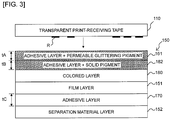
- the adhesive tape 150 N includes: an image receiving layer 210 ; the colored layer 180 similar to the above; the transparent film layer 151 A that is transparent (or translucent is acceptable; the same applies hereinafter) similar to the above, the adhesive layer 161 to which the permeable glittering pigment is added similar to the above, the adhesive layer 162 to which the solid pigment is added similar to the above, and the separation material layer 152 , laminated in the mentioned order from the spool 50 lying on the radial center side (corresponding to the upper side in FIG. 16 described later) toward the radial outside (corresponding to the lower side in FIG. 16 described later).
- the platen roller 24 presses the adhesive tape 150 N fed out from the adhesive tape roll 14 and an ink ribbon not shown fed out from the ink ribbon roll 16 against the thermal head 23 .
- ink of the ink ribbon is transferred onto the image receiving layer 210 of the adhesive tape 150 N by heat reception from the thermal head 23 so that a desired print R (see FIG. 3 , etc. described later) is formed on the adhesive tape 150 N to obtain a print tape 100 N so that the platen roller 24 feeds the print tape 100 N having the print formed thereon and the ink ribbon toward the feeding roller 18 .
- the feeding roller 18 further feeds the print tape 100 N toward the label discharging exit 29 disposed on the upper end of the device body 2 .
- the user manually operates the cutting operation lever 6 to activate the cutter 28 disposed in the vicinity of the label discharging exit 29 , to cut the print tape 100 N into a desired length of print tape 100 N (i.e. print label).
- FIG. 16 is an explanatory view showing layered structures of the adhesive tape 150 N and the print tape 100 N corresponding to FIGS. 3 and 4 of the first embodiment.
- the adhesive tape 150 N includes: the transparent film layer 151 A; the colored layer 180 disposed in contact with the transparent film layer 151 A on the upper side of the diagram; the image receiving layer 210 disposed in contact with the colored layer 180 on the upper side of the diagram; the adhesive layer 161 disposed in contact with the transparent film layer 151 A on the lower side of the diagram, the adhesive layer 161 having the permeable glittering pigment added at a desired volume ratio (5-50% relative to the entire adhesive layer); the adhesive layer 162 disposed in contact with the adhesive layer 161 on the lower side of the diagram, the adhesive layer 162 having the solid pigment added at a desired volume ratio (5-50% relative to the entire adhesive layer); and the separation material layer 152 disposed in contact with the adhesive layer 162 on the lower side of the diagram so as to cover the adhesive layer 162 .
- this embodiment has a feature that the volume ratio of the solid pigment in the adhesive layer 162 is smaller than the volume ratio of the permeable glittering pigment in the adhesive layer 161 .
- the volume ratio of the permeable glittering pigment in the adhesive layer 161 is 1.5 times or more the volume ratio of the solid pigment in the adhesive layer 162 .
- the volume ratio can be measured by the technique similar to that in the first embodiment for example.
- the solid pigment in the adhesive layer 162 and the permeable glittering pigment in the adhesive layer 161 are made of the same material.
- the permeable glittering pigment contained in the adhesive layer 161 has a transmittance of 20% or more.
- the image receiving layer 210 also has a transmittance of 20% or more.
- FIG. 16B shows a layered structure of the print tape 100 N in which print R is formed on the image receiving layer 210 of the adhesive tape 150 N.
- a manufacturing process of the adhesive tape 150 N will next be described with reference to FIGS. 17 and 18 .
- the transparent film layer 151 A having the image receiving layer 210 and the colored layer 180 formed thereon by the known printing technique for example is fed out from the film roll FR and is supplied to the adhesive coating head AH.
- an adhesive (containing the permeable glittering pigment) of the above composition is applied to a surface of the transparent film layer 151 A opposite to the colored layer 180 , to obtain a four-layered structure including the image receiving layer 210 , the colored layer 180 , the transparent film layer 151 A, and the adhesive layer 161 (to which the permeable glittering pigment is added), after which the structure passes through the first drying chamber D 1 , the second drying chamber D 2 , the third drying chamber D 3 , the fourth drying chamber D 4 , and the fifth drying chamber D 5 , in the mentioned order to undergo the five-stage drying process and is wound onto the first tape roll TR 1 .
- the number of the drying chambers is not limited to five.
- the tape of the four-layered structure including the image receiving layer 210 , the colored layer 180 , the transparent film layer 151 A, and the adhesive layer 161 is fed out from the first tape roll TR 1 and is supplied to the adhesive coating head AH in the same manner as the above.
- an adhesive (containing the solid pigment) of the above composition is applied to a surface of the adhesive layer 161 opposite to the film layer 151 A, to obtain a five-layered structure including the image receiving layer 210 , the colored layer 180 , the transparent film layer 151 A, the adhesive layer 161 , and the adhesive layer 162 (to which the solid pigment is added), after which similarly to the above, the structure passes through the first to fifth drying chambers D 1 to D 5 , in the mentioned order, to undergo the drying process.
- the configuration may be such that the image receiving layer 210 is disposed in contact with the transparent film layer 151 A on the upper side of the diagram, without interposing the colored layer 180 between the image receiving layer 210 and the transparent film layer 151 A.
- the colored layer 180 may be disposed in contact with the transparent film layer 151 A on the upper side of the diagram, without disposing the image receiving layer 210 .
- This third embodiment can also present an advantage similar to that of the first and the second embodiments and the modification examples. If desired to use two different pigments with the intention of obtaining two different colors for example in the adhesive tape, intermixture of those pigments within a single layer brings about interference between the two pigments, hindering the pigments from fully exerting their respective effects.
- the number of layers of the entire tape is limited to six, so that the increase in the total thickness of the adhesive tape 150 N and in the number of manufacturing steps can be suppressed. As a result, regardless of a limited space, the tape length capable of being wound onto the adhesive tape roll 14 can be extended.
- the volume ratio of the solid pigment in the adhesive layer 162 is set to be less than the volume ratio of the permeable glittering pigment in the adhesive layer 161 .
- the adhesive layer 161 disposed on one side in the thickness direction of the transparent film layer 151 A is bonded to the transparent film layer 151 A while being managed in the factory manufacturing facility for example at the time of manufacturing as described above using FIGS. 17 and 18 .
- the adhesive layer 162 needs to have a bonding force greater than that of the adhesive layer 161 because the adherend has not yet been determined and because the adhesion is made by the user.
- This third embodiment can deal with the above by setting the volume ratio of the solid pigment in the adhesive layer 162 to be less than the volume ratio of the permeable glittering pigment in the adhesive layer 161 .
- the permeable glittering pigment of the adhesive layer 161 has a transmittance of 20% or more. This ensures a reliable visual recognition of the color of the solid pigment of the adhesive layer 162 on the far side when viewed from the other side (upper side in FIGS. 16 and 19 ) in the thickness direction. Since the permeable glittering pigment having permeability is added to a layer separate from the solid pigment, the glitter feeling from the permeable glittering pigment of the adhesive layer 161 can be restrained from being disappeared by the solid pigment of the adhesive layer 162 .
- the volume ratio of the permeable glittering pigment in the adhesive layer 161 is 1.5 times or more the volume ratio of the solid pigment in the adhesive layer 162 .
- a large amount of first pigment can be added due to less restriction from the bonding force, and the addition of 1.5 times or more can enhance the chroma and glitter feeling.
- the adhesive layer 162 with the solid pigment added may be replaced by the adhesive layer 162 A with the coloring glittering pigment added.
- the coloring glittering pigment is added at a volume ratio of 5-50% for example relative to the entire adhesive layer.
- the colored layer 180 may be removed from the layered structure of the adhesive tape 150 N shown in FIG. 22A (in this case, the same layered structure as in FIG. 20B results).
- the image receiving layer 210 may be removed from the layered structure of the adhesive tape 150 N shown in FIG. 22A .
- the particle diameter of 40 ⁇ m or more ensures visual confirmation of particle feeling, and therefore the overlying arrangement cannot impair the particle feeling as compared with the underlying arrangement.
- the particle feeling becomes more noticeable (60 ⁇ m or more is even better).
- the overlying particle feeling can hardly be impaired.
- the glittering pigment is added to the adhesive layer 162 B in a volume ratio of 5-50% for example relative to the entire adhesive layer in the same manner as the adhesive layer 162
- the permeable glittering pigment is added to the adhesive layer 161 B in a volume ratio of 5-50% for example relative to the entire adhesive layer in the same manner as the adhesive layer 161
- the permeable glittering pigment contained in the adhesive layer 161 B has a transmittance of 20% or more.
- the colored layer 180 may be removed from the structure shown in FIG. 23A .
- the image receiving layer 210 may be removed from the structure shown in FIG. 23A .
- the average particle diameter of the glittering pigment in the adhesive layer 162 B is smaller than the average particle diameter of the permeable glittering pigment in the adhesive layer 161 B.
- the glittering pigment with a small average particle diameter is located on the far side while the permeable glittering pigment with a large average particle diameter is located on the near side when viewed from the other side (upper side in FIG. 23 ) in the thickness direction, a high brilliance and depth can be obtained.
- the transparent film layer 151 A and the colored layer 180 may be interchanged so that the image receiving layer 210 , the transparent film layer 151 A, the colored layer 180 , the adhesive layer 161 A, the adhesive layer 162 A, and the separation material layer 152 are laminated in the mentioned order from the upper side toward the lower side of the diagram.
- the colored layer 180 may be removed from the layered structure of the adhesive tape 150 N shown in FIG. 24A (in this case, the same layered structure as in FIG. 23B results).
- the image receiving layer 210 may be removed from the layered structure of the adhesive tape 150 N shown in FIG. 24A .
- the transparent film layer 151 A may be removed from the structure shown in FIGS. 15 to 24 . At that time, the structure without the film layer may be expanded to the laminated type.
- Such modification examples will be described with reference to FIGS. 25 to 27 .
- the same reference numerals are imparted to parts equivalent to those of the first to the third embodiments and modification examples thereof, and explanations thereof will appropriately be omitted or simplified.
- FIG. 25 illustrates a plan view, corresponding to FIG. 2 of the first embodiment and showing a rear internal structure of a device body of a print label producing apparatus in this modification example.
- the double-sided adhesive tape 150 wound onto the adhesive tape roll 14 disposed in the housing 11 A of the cartridge 11 of this embodiment is configured to include: as shown in an enlarged view of FIG.
- the print-receiving tape roll 15 is made up by winding the print-receiving tape 110 having a transmittance of 20% or more for example around the spool 60 .
- the housing 11 A comprises the ink ribbon roll 16 similar to the above.
- FIG. 26 is an explanatory view showing a layered structure of the print-receiving tape 110 and the double-sided adhesive tape 150 .
- this modification example has a feature that the volume ratio of the solid pigment in the adhesive layer 162 is smaller than the volume ratio of the permeable glittering pigment in the adhesive layer 161 .
- the volume ratio of the permeable glittering pigment in the adhesive layer 161 is 1.5 times or more the volume ratio of the solid pigment in the adhesive layer 162 .
- the volume ratio can be measured by the technique similar to that in the first embodiment for example.
- the permeable glittering pigment contained in the adhesive layer 161 has a transmittance of 20% or more.
- FIG. 27A shows a layered structure of the print tape 100 formed by bonding the print-receiving tape 110 and the double-sided adhesive tape 150 together
- FIG. 27B shows a state where the print tape 100 is adhered via the adhesive layer 162 to the adherend M with the separation material layer 152 being separated from the print tape 100 .
- the print tape 100 is made up by laminating, from the upper side in the diagram toward the lower side in the diagram, the print-receiving tape 110 , the adhesive layer 161 (to which the permeable glittering pigment is added), the adhesive layer 162 (to which the solid pigment is added), the colored layer 180 , the film layer 151 , the adhesive layer 170 , and the separation material layer 152 , in the mentioned order.
- This modification example also presents an advantage similar to that of the third embodiment.
- FIGS. 28 to 44 A fourth embodiment of the present disclosure will be described with reference to FIGS. 28 to 44 .
- the same reference numerals are imparted to parts equivalent to those in the first to the third embodiments and their modification examples, and explanations thereof will appropriately be omitted or simplified.
- FIG. 28 illustrates a plan view corresponding to FIG. 2 of the first embodiment and showing a rear internal structure of a device body of a print label producing apparatus in the fourth embodiment.
- the double-sided adhesive tape 150 wound onto the adhesive tape roll 14 disposed in the housing 11 A of the cartridge 11 of this embodiment is configured to include: as shown in an enlarged view of FIG.
- an adhesive layer 163 U with predetermined particles (a pigment in this example; it may be a glittering pigment in particular; the same applies hereinafter) added; an adhesive layer 163 L with particles of the same material as in the adhesive layer 163 U (the glittering pigment in this example; the same applies hereinafter) added; the colored layer 180 ; the film layer 151 , the adhesive layer 170 ; and the separation material layer 152 ; laminated in the mentioned order from the spool 50 lying on the radial center side (corresponding to the upper side in FIG. 29 described later) toward the radial outside (corresponding to the lower side in FIG. 29 described layer). Similar to the above, as shown in FIG.
- the print-receiving tape roll 15 is made up by winding the print-receiving tape 110 having a transmittance of 20% or more for example around the spool 60 .
- the housing 11 A comprises the ink ribbon roll 16 similar to the above.
- FIG. 29 is an explanatory view showing a layered structure of the print-receiving tape 110 and the double-sided adhesive tape 150 .
- the volume ratio of the pigment in the adhesive layer 163 U is smaller than the volume ratio of the pigment in the adhesive layer 163 L. Specifically, the volume ratio of the pigment in the adhesive layer 163 L is 1.5 times or more the volume ratio in the adhesive layer 163 U.
- a thickness tL of the adhesive layer 163 L is greater than a thickness tU of the adhesive layer 163 U. Specifically the thickness tL of the adhesive layer 163 L is 1.5 times or more the thickness tU of the adhesive layer 163 U.
- the adhesive force of the adhesive layer 163 U is 3 [N]/10 [mm] or more.
- the adhesive force (bonding force) is measured in conformity with JIS-Z0237. To put it briefly, a surface to be measured is affixed to an SUS304 stainless plate and, after the elapse of a certain period of time, a tensile tester is used to perform a measurement separating at an angle of 180 degrees at a speed of 300 mm/min (hereinafter, the same will apply to modification examples and other embodiments described later).
- the colored layer 180 has a transmittance of 20% or more.
- the print-receiving tape 110 has print R as described above on a surface on the side facing the double-sided adhesive tape 150 (the lower side of the diagram).
- the print-receiving tape 110 is bonded via the adhesive layer 163 U to the double-sided adhesive tape 150 .
- FIG. 30A shows a layered structure of the print tape 100 formed by bonding the print-receiving tape 110 and the double-sided adhesive tape 150 together
- FIG. 30B shows a state where the print tape 100 is adhered via the adhesive layer 170 to the adherend M with the separation material layer 152 being separated from the print tape 100 .
- the print tape 100 is made up by laminating, from the upper side of the diagram toward the lower side thereof, the print-receiving tape 110 , the adhesive layer 163 U (to which the glittering pigment is added), the adhesive layer 163 L (to which the glittering pigment is added), the colored layer 180 , the film layer 151 , the adhesive layer 170 , and the separation material layer 152 , in the mentioned order.
- the adhesive layer 163 L may be disposed in contact with the film layer 151 on the upper side of the diagram, without interposing the colored layer 180 between the adhesive layer 163 L and the film layer 151 .
- three or more adhesive layers having common particles, inclusive of the two adhesive layers 163 U and 163 L, may be disposed adjacent to one another.
- a manufacturing process of the double-sided adhesive tape 150 will next be described with reference to FIGS. 32 to 34 .
- the film layer 151 having the colored layer 180 formed thereon by a known printing technique for example is fed out from the film roll FR and is supplied to the adhesive coating head AH.
- an adhesive of the above composition is applied to a surface of the film layer 151 opposite to the colored layer 180 , to obtain a three-layered structure including the colored layer 180 , the film layer 151 , and the adhesive layer 170 , after which the structure passes through the first drying chamber D 1 , the second drying chamber D 2 , the third drying chamber D 3 , the fourth drying chamber D 4 , and the fifth drying chamber D 5 , in the mentioned order, to undergo a five-stage drying process.
- the number of the drying chambers is not limited to five.
- the separation material layer 152 fed out separately from the separation material roll SR is bonded to the adhesive layer 170 so that the tape of the three-layered structure turns into a tape of a four-layered structure, which is wound onto the first tape roll TR 1 .
- the tape of the four-layered structure including the colored layer 180 , the film layer 151 , the adhesive layer 170 , and the separation material layer 152 is fed out from the first tape roll TR 1 and is supplied to the adhesive coating head AH in the same manner as the above.
- an adhesive (containing the glittering pigment as the particles for example) of the above composition is applied to a surface of the colored layer 180 opposite to the film layer 151 , to obtain a five-layered structure including the adhesive layer 163 L (having the glittering pigment added), the colored layer 180 , the film layer 151 , the adhesive layer 170 , and the separation material layer 152 , after which similarly to the above, the structure passes through the first to fifth drying chambers D 1 to D 5 , in the mentioned order, to undergo the drying process and is wound onto the second tape roll TR 2 .
- the tape of the five-layered structure including the adhesive layer 163 L, the colored layer 180 , the film layer 151 , the adhesive layer 170 , and the separation material layer 152 is fed out from the second tape roll R 2 and is supplied to the adhesive coating head AH in the same manner as the above.
- an adhesive containing the same particles as the above, e.g.
- the glittering pigment) the permeable glittering pigment) of the above composition is applied to a surface of the adhesive layer 163 L opposite to the colored layer 180 , to obtain a six-layered structure including the adhesive layer 163 U (having the glittering pigment added), the adhesive layer 163 L (having the glittering pigment added), the colored layer 180 , the film layer 151 , the adhesive layer 170 , and the separation material layer 152 , after which similarly to the above, the structure passes through the first to fifth drying chambers D 1 to D 5 , in the mentioned order, to undergo the drying process to complete the double-sided adhesive tape 150 .
- the thus completed double-sided adhesive tape 150 is wound onto the third tape roll TR 3 .
- FIGS. 32 to 34 the case has been described by way of example where the adhesive coating head AH is disposed only at a single location, another adhesive coating head AH may separately be disposed downstream of the drying chamber D 5 along the transport path. In this case, intactly after the coating process of the adhesive layer 163 L and the drying process through the drying chambers D 1 to D 5 in FIG. 33 , the coating process of the adhesive layer 163 U (described using FIG. 34 ) can be performed.
- a solvent (used at the time of dilution) contained in the interior of a layer adhesively coated at the adhesive coating head AH may not fully volatilize even through the subsequent drying process in the drying chambers D 1 to D 5 and may remain within the adhesive layer (see broken line portions of FIG. 35 ). Since the adhesive performance of the adhesive layer is adversely affected if the solvent remains within the adhesive layer, there is a need to lower the coating speed or strengthen the drying conditions in order to avoid the adverse effect, resulting in increased manufacturing costs. The above trend becomes noticeable esp. when using particles with a large particle diameter (particles with an average particle diameter of 30 ⁇ m or more as in this embodiment for example).
- the adhesive layer with the above particles added is divided into two (the adhesive layer 163 L and the adhesive layer 163 U) (see FIG. 36A ) so that the adhesive layer 163 L with the above particles added is first disposed on one side (the upper side in FIGS. 29 to 31 ) in the thickness direction of the film layer 151 (see the overall process shown in FIG. 33 ) while the adhesive layer 163 U with the same particles added is disposed on one side (the upper side in FIGS. 29 to 31 ) in the thickness of the adhesive layer 163 L.
- the thickness of one adhesive layer 163 U (or adhesive layer 163 L) can be reduced so that the solvent can easily dry through the drying process in the drying chambers D 1 to D 5 (see solid arrows in FIG. 36B ) so that the lowering in the adhesive performance of the adhesive layers 163 U and 163 L arising from the residual solvent can be suppressed.
- the pigment is added as the above particles to the adhesive layer 163 L and the adhesive layer 163 U. This enables the brilliance from the pigment to be secured.
- the volume ratio of the particles (the pigment in the above example) in the adhesive layer 163 U is smaller than the volume ratio of the pigment in the adhesive layer 163 L. This enables the adhesive performance of the adhesive layer 163 U exposed on the surface to be secured. In other words, the bonding performance of the entire tape can be secured.
- the volume ratio of the pigment in the adhesive layer 163 L is 1.5 times or more the volume ratio in the adhesive layer 163 U. This has the following technical significance.
- the second-particle-containing adhesive layer may have a smaller volume ratio, the reason is that the second pigment is on the bonding side and therefore requires an adhesive force.
- the first pigment is increased to compensate for the decrease in the second pigment.
- the bonding force is insufficient, requiring an increase in the thickness of the adhesive layer.
- 1.5 times or more preferably, 2 times or more is preferred.
- the adhesive layer 163 L disposed on the film layer 151 (having the colored layer 180 formed thereon) is bonded to the colored layer 180 at the time of manufacturing in the state where it is managed in the factory manufacturing facility shown in FIGS. 32 to 34 for example.
- the adhesive layer 163 U is bonded to the print-receiving tape 110 within the print label producing apparatus 1 at the time of the print label production as described hereinabove.
- the bonding force of the adhesive layer 163 U needs to be greater than that of the adhesive layer 163 L.
- this fourth embodiment can deal with the above by setting the volume ratio of the particles in the adhesive layer 163 U to be smaller than the volume ratio of the particles in the adhesive layer 163 L.
- the thickness tL of the adhesive layer 163 L is set to be greater (than the thickness tU of the adhesive layer 163 U) so that the volume ratio of the particles in the adhesive layer 163 L can further be increased.
- Such an increase allows the residual amount of the solvent in the adhesive layer 163 L to relatively increase but allows the residual amount of the solvent in the adhesive layer 163 U to relatively decrease.
- the thickness tL of the adhesive layer 163 L is 1.5 times or more the thickness tU of the adhesive layer 163 U. This has the following technique significance.
- the second pigment is reduced to 2 ⁇ 3 or less (desirably, 1 ⁇ 2 or less) to obtain a minimum thickness capable of securing the bonding force of 3 N/10 mm (for the purpose of preventing the total layer thickness from increasing). Such a reduction increases the ratio of the first pigment, requiring the 1.5 times or more thickness.
- the adhesive force of the adhesive layer 163 U is 3 [N]/10 [mm] or more. As a result, the adhesiveness by the adhesive layer 163 U can be ensured.
- the film layer 151 and the adhesive layer 170 may be removed.
- Such a modification example will be described with reference to FIGS. 37 to 39 .
- the same reference numerals are imparted to parts equivalent to those of the fourth embodiment and explanations thereof will appropriately be omitted or simplified.
- FIG. 37 illustrates a plan view corresponding to FIG. 28 of the fourth embodiment and showing a rear internal structure of a device body of a print label producing apparatus in this modification example.
- the double-sided adhesive tape 150 wound onto the adhesive tape roll 14 disposed in the housing 11 A of the cartridge 11 of this modification example is configured to include: as shown in an enlarged view of FIG.
- the print-receiving tape roll 15 is made up by winding the print-receiving tape 110 having a transmittance of 20% or more for example around the spool 60 .
- the housing 11 A comprises the ink ribbon roll 16 similar to the above.
- FIG. 38 is an explanatory view showing a layered structure of the print-receiving tape 110 and the double-sided adhesive tape 150 .
- the double-sided adhesive tape 150 includes: the adhesive layer 163 L to which the pigment is added at a desired volume ratio; the adhesive layer 163 U disposed in contact with the adhesive layer 163 L on the upper side of the diagram and having the pigment of the same material as in the adhesive layer 163 L added at a desired volume ratio; and the separation material layer 152 disposed in contact with the adhesive layer 163 L on the lower side of the diagram so as to cover the adhesive layer 163 L.
- FIG. 39A shows a layered structure of the print tape 100 formed by bonding the print-receiving tape 110 and the double-sided adhesive tape 150 together
- FIG. 39B shows a state where the print tape 100 is adhered via the adhesive layer 162 to the adherend M with the separation material layer 152 being separated from the print tape 100
- the print tape 100 is made up by laminating, from the upper side of the diagram toward the lower side thereof, the print-receiving tape 110 , the adhesive layer 163 U (to which a pigment is added), the adhesive layer 163 L (to which the pigment is added), and the separation material layer 152 , in the mentioned order.
- This modification example also presents an advantage similar to that of the fourth embodiment.
- the fourth embodiment is not limited to the above mode and can variously be modified without departing from its spirit and technical idea. Modification examples thereof will be described hereinbelow in order.
- This modification example uses a cartridge called a so-called non-laminated type (in more detail, receptor type), in the same manner as in FIG. 15 of the third embodiment described above.
- the cartridge 11 for use in this modification example comprises, within the housing 11 A, similarly to FIG. 15 , the adhesive tape roll 14 (of which detailed Layered Structure will be described later), the ink ribbon roll 16 , the ink ribbon take-up roller 17 , and the feeding roller 18 .
- the adhesive tape roll 14 is made up by winding the adhesive tape 150 N related to this modification example around the spool 50 .
- the adhesive tape 150 N includes: the image receiving layer 210 ; the colored layer 180 ; the transparent film layer 151 A that is transparent (or translucent is also acceptable; the same will apply hereinafter) similar to the above; the adhesive layer 163 L to which predetermined particles (a pigment in this example; it may be a glittering pigment in particular; the same will apply hereinafter) similar to those in FIG.
- the adhesive layer 163 U to which particles (the glittering pigment in this example; the same will apply hereinafter) of the same material as in the adhesive layer 163 L are added; and the separation material layer 152 ; laminated in the mentioned order from the spool 50 lying on the radial center side (corresponding to the upper side in FIG. 41 described later) toward the radial outside (corresponding to the lower side in FIG. 41 described later).
- FIG. 41A is an explanatory view showing a layered structure of the adhesive tape 150 N and the print tape 100 N.
- the adhesive tape 150 N includes: the transparent film layer 151 A; the colored layer 180 disposed in contact with the transparent film layer 151 A on the upper side of the diagram (the other side in the thickness direction in the structures of FIGS. 40 to 44 ); the image receiving layer 210 disposed in contact with the colored layer 180 on the upper side of the diagram; the adhesive layer 163 L disposed in contact with the transparent film layer 151 A on the lower side of the diagram and having the pigment added at a desired volume ratio; the adhesive layer 163 U disposed in contact with the adhesive layer 163 L on the lower side of the diagram and having the pigment of the same material as in the adhesive layer 163 L added at a desired volume ratio; and the separation material layer 152 disposed in contact with the adhesive layer 163 U on the lower side of the diagram so as to cover the adhesive layer 163 U.
- the average particle diameter of the pigment in the adhesive layers 163 U and 163 L is 30 ⁇ m or more.
- the average particle diameter can be measured by the technique similar to the above.
- the volume ratio of the pigment in the adhesive layer 163 U is smaller than the volume ratio of the pigment in the adhesive layer 163 L. Specifically, the volume ratio of the pigment in the adhesive layer 163 L is 2 times or more the volume ratio in the adhesive layer 163 U.
- the volume ratio can be measured by the technique described above.
- the thickness tL of the adhesive layer 163 L is greater than the thickness tU of the adhesive layer 163 U. Specifically, the thickness tL of the adhesive layer 163 L is 1.5 times or more the thickness tU of the adhesive layer 163 U.
- the adhesive force of the adhesive layer 163 U is 3 [N]/10 [mm] or more.
- the colored layer 180 has a transmittance of 20% or more. In this modification example, the image receiving layer 210 also has a transmittance of 20% or more.
- FIG. 41B shows a layered structure of the print tape 100 N having print R formed on the image receiving layer 210 of the adhesive tape 150 N.
- FIGS. 42 and 43 A manufacturing process of the adhesive tape 150 N will next be described using FIGS. 42 and 43 .
- the transparent film layer 151 A having the image receiving layer 210 and the colored layer 180 formed thereon by a known printing technique is fed out from the film roll FR and is supplied to the adhesive coating head AH.
- an adhesive (containing the pigment) of the above composition is applied to a surface of the transparent film layer 151 A opposite to the colored layer 180 , to obtain a four-layered structure including the image receiving layer 210 , the colored layer 180 , the transparent film layer 151 A, and the adhesive layer 163 L (with the pigment added), after which the structure passes through the first drying chamber D 1 , the second drying chamber D 2 , the third drying chamber D 3 , the fourth drying chamber D 4 , and the fifth drying chamber D 5 , in the mentioned order, to undergo the five-stage drying process, and is wound onto the first tape roll TR 1 .
- the number of the drying chambers is not limited to five.
- the tape of the four-layered structure including the image receiving layer 210 , the colored layer 180 , the transparent film layer 151 A, and the adhesive layer 163 L is fed out from the first tape roll TR 1 and is supplied to the adhesive coating head AH in the same manner as the above.
- an adhesive (containing the same pigment as the above) of the above composition is applied to a surface of the adhesive layer 163 L opposite to the transparent film layer 151 A, to obtain a five-layered structure including the image receiving layer 210 , the colored layer 180 , the transparent film layer 151 A, the adhesive layer 163 L, and the adhesive layer 163 U (with the pigment added), after which similarly to the above, the structure passes through the first to fifth drying chambers D 1 to D 5 , in the mentioned order, to undergo the drying process.
- the separation material layer 152 separately fed out from the separation material roll SR is bonded to the adhesive layer 163 U of the tape of the 5-layered structure, to complete the adhesive tape 150 N of a six-layered structure including the image receiving layer 210 , the colored layer 180 , the transparent film layer 151 A, the adhesive layer 163 L, the adhesive layer 163 U, and the separation material layer 152 .
- the thus completed adhesive tape 150 N is wound onto the second tape roll TR 2 .
- FIGS. 42 and 43 the case has been described by way of example where the adhesive coating head AH is disposed only at a single location, another adhesive coating head AH may separately be disposed downstream of the drying chamber D 5 along the transport path.
- another adhesive coating head AH may separately be disposed downstream of the drying chamber D 5 along the transport path.
- the configuration may be such that the image receiving layer 210 is disposed in contact with the transparent film layer 151 A on the upper side of the diagram, without interposing the colored layer 180 between the image receiving layer 210 and the transparent film layer 151 A.
- the colored layer 180 may be disposed in contact with the transparent film layer 151 A on the upper side of the diagram, without disposing the image receiving layer 210 .
- This modification example can also present an advantage similar to that of the fourth embodiment.
- the adhesive layer with particles added is divided into two (the adhesive layer 163 L and the adhesive layer 163 U) so that the adhesive layer 163 L with the above particles added is disposed on one side (the lower side in FIG. 41 ) in the thickness direction of the transparent film layer 151 A while the adhesive layer 163 U with the same particles added is disposed on one side (the lower side in FIG. 41 ) in the thickness direction of the adhesive layer 163 L.
- the thickness of one adhesive layer 163 U (or adhesive layer 163 L) can be reduced so that the solvent can easily dry through the drying process in the drying chambers D 1 to D 5 so that the lowering in the adhesive performance of the adhesive layers 163 U and 163 L arising from the residual solvent can be suppressed.
- the glittering pigment is added as the above particles to the adhesive layer 163 L and the adhesive layer 163 U, enabling the brilliance from the pigment to be secured.
- the volume ratio of the particles (the pigment in the above example) in the adhesive layer 163 U is smaller than the volume ratio of the pigment in the adhesive layer 163 L, thereby enabling the adhesive performance of the adhesive layer 163 U exposed on the surface to be secured, i.e., enabling the bonding performance of the entire tape to be secured.
- the thickness tL of the adhesive layer 163 L is set to be greater (than the thickness tU of the adhesive layer 163 U) so that the volume ratio of the particles in the adhesive layer 163 L can further be increased.
- the adhesive layer 163 L disposed on the transparent film layer 151 A is bonded to the transparent film layer 151 A while being managed in the factory manufacturing facility for example at the time of manufacturing, as described above using FIG. 42 .
- the adhesive layer 163 U needs to have a bonding force greater than that of the adhesive layer 163 L because the adherend has not yet been determined and because the adhesion is made by the user.
- This modification example can deal with the above by setting the volume ratio of the pigment in the adhesive layer 163 U to be less than the volume ratio of the pigment in the adhesive layer 163 L.
- the transparent film layer 151 A and the colored layer 180 may be interchanged so that the image receiving layer 210 , the transparent film layer 151 A, the colored layer 180 , the adhesive layer 163 L, the adhesive layer 163 U, and the separation material layer 152 are laminated in the mentioned order from the upper side (the other side in the thickness direction) of the diagram toward the lower side (one side in the thickness direction) of the diagram.
- the colored layer 180 may be removed from the layered structure of the adhesive tape 150 N shown in FIG. 44A (in this case, the same layered structure as in FIG. 41C results).
- the image receiving layer 210 may be removed from the layered structure of the adhesive tape 150 N shown in FIG. 44A .
- the transparent film layer 151 A and the colored layer 180 may be removed from the structure shown in FIG. 44A .
- Such a modification example will be described with reference to FIG. 46 .
- the same reference numerals are imparted to parts equivalent to those in the fourth embodiment and its modification examples, and explanations thereof will appropriately be omitted or simplified.
- FIG. 45 illustrates a plan view corresponding to FIG. 40 and showing a rear internal structure of a device body of a print label producing apparatus in this modification example.
- the cartridge 11 for use in this modification example comprises, within the interior of the housing 11 A, the adhesive tape roll 14 , the ink ribbon roll 16 , the ink ribbon take-up roller 17 , and the feeding roller 18 .
- the adhesive tape roll 14 is made up by winding the adhesive tape 150 N in relation to this modification example around the spool 50 .
- the adhesive tape 150 N includes: the image receiving layer 210 similar to the above; the adhesive layer 163 L with predetermined particles (a pigment in this example) similar to the above added; the adhesive layer 163 U with particles (the pigment in this example; the same will apply hereinafter) of the same material as in the adhesive layer 163 L added; and the separation material layer 152 , laminated in the mentioned order from the spool 50 lying on the radial center side in FIG. 45 (corresponding to the upper side in FIG. 46 described later) toward the radial outside (corresponding to the lower side in FIG. 46 described later).
- FIG. 46A is an explanatory view showing a layered structure of the adhesive tape 150 N according to this modification example.
- the adhesive tape 150 N includes: the adhesive layer 163 L having the pigment added at a desired volume ratio; the image receiving layer 210 disposed in contact with the adhesive layer 163 L on the upper side of the diagram; the adhesive layer 163 U disposed in contact with the adhesive layer 163 L on the lower side of the diagram and having the pigment of the same material as in the adhesive layer 163 L added at a desired volume ratio; and the separation material layer 152 disposed in contact with the adhesive layer 163 U on the lower side of the diagram so as to cover the adhesive layer 163 U.
- FIG. 46B shows a layered structure of the print tape 100 N in which print R is formed on the image receiving layer 210 of the adhesive tape 150 N.
- This modification example also presents an advantage similar to the above.
- the measurement is made by cutting the tape into at least 10 mm ⁇ 10 mm.
Landscapes
- Chemical & Material Sciences (AREA)
- Organic Chemistry (AREA)
- Adhesive Tapes (AREA)
- Laminated Bodies (AREA)
- Printers Characterized By Their Purpose (AREA)
- Impression-Transfer Materials And Handling Thereof (AREA)
- Adhesives Or Adhesive Processes (AREA)
Abstract
Description
Claims (19)
Applications Claiming Priority (4)
| Application Number | Priority Date | Filing Date | Title |
|---|---|---|---|
| JPJP2016-195294 | 2016-09-30 | ||
| JP2016-195294 | 2016-09-30 | ||
| JP2016195294A JP6729259B2 (en) | 2016-09-30 | 2016-09-30 | Adhesive tape roll manufacturing method and adhesive tape cartridge manufacturing method |
| PCT/JP2017/033737 WO2018061874A1 (en) | 2016-09-30 | 2017-09-19 | Adhesive tape cartridge, adhesive tape roll, and production method for adhesive tape roll |
Related Parent Applications (1)
| Application Number | Title | Priority Date | Filing Date |
|---|---|---|---|
| PCT/JP2017/033737 Continuation-In-Part WO2018061874A1 (en) | 2016-09-30 | 2017-09-19 | Adhesive tape cartridge, adhesive tape roll, and production method for adhesive tape roll |
Publications (2)
| Publication Number | Publication Date |
|---|---|
| US20190218420A1 US20190218420A1 (en) | 2019-07-18 |
| US10995241B2 true US10995241B2 (en) | 2021-05-04 |
Family
ID=61760818
Family Applications (1)
| Application Number | Title | Priority Date | Filing Date |
|---|---|---|---|
| US16/366,270 Active 2037-10-07 US10995241B2 (en) | 2016-09-30 | 2019-03-27 | Adhesive tape cartridge, adhesive tape roll, and method of manufacturing an adhesive tape roll |
Country Status (4)
| Country | Link |
|---|---|
| US (1) | US10995241B2 (en) |
| EP (1) | EP3521392A4 (en) |
| JP (1) | JP6729259B2 (en) |
| WO (1) | WO2018061874A1 (en) |
Families Citing this family (4)
| Publication number | Priority date | Publication date | Assignee | Title |
|---|---|---|---|---|
| JP6729258B2 (en) * | 2016-09-30 | 2020-07-22 | ブラザー工業株式会社 | Adhesive tape cartridge and adhesive tape roll manufacturing method |
| JP7745342B2 (en) | 2018-03-26 | 2025-09-29 | 味の素株式会社 | Method for producing starch-containing foods |
| JP1751540S (en) * | 2023-01-27 | 2023-08-24 | ||
| JP1751541S (en) * | 2023-01-27 | 2023-08-24 |
Citations (16)
| Publication number | Priority date | Publication date | Assignee | Title |
|---|---|---|---|---|
| JPS58101176A (en) | 1981-12-11 | 1983-06-16 | Modern Plast Kogyo Kk | Metallic pressure-sensitive adhesive sheet having excellent luster |
| JPS58101051A (en) | 1981-12-12 | 1983-06-16 | モダン・プラスチツク工業株式会社 | Metal-like colored adhesive sheet having excellent brightness |
| JPH06157997A (en) | 1992-11-18 | 1994-06-07 | Sekisui Chem Co Ltd | Polysryrene tacky tape and its production |
| JPH11106713A (en) | 1997-10-03 | 1999-04-20 | Sekisui Chem Co Ltd | Adhesive sheet |
| JP2003195768A (en) | 2001-12-27 | 2003-07-09 | Sato Corp | Labelless base paper and its printing and issuing device |
| WO2006094079A2 (en) | 2005-03-03 | 2006-09-08 | 3M Innovative Properties Company | Thermosettable adhesive tape, articles and methods |
| US20070147937A1 (en) * | 2005-12-28 | 2007-06-28 | Brother Kogyo Kabushiki Kaisha | Print tape and print cassette |
| US20070252704A1 (en) * | 2006-04-13 | 2007-11-01 | Tsuyoshi Nagae | RFID label |
| US20080026205A1 (en) | 2006-07-28 | 2008-01-31 | Takayuki Sasaki | Heat-sensitive pressure-sensitive adhesive and heat-sensitive adhesive material |
| JP2008063435A (en) | 2006-09-07 | 2008-03-21 | Ricoh Co Ltd | Heat sensitive adhesive and heat sensitive adhesive material |
| JP2012041456A (en) | 2010-08-19 | 2012-03-01 | Daido Kasei Kogyo Kk | Acrylic polymeric compound for use in self-adhesive composition for touch panel |
| US20130082789A1 (en) | 2010-06-17 | 2013-04-04 | Fumihiro Inoue | Oscillation circuit and operating current control method thereof |
| JP2013082789A (en) | 2011-10-07 | 2013-05-09 | Brother Industries Ltd | Pressure-sensitive adhesive for pressure-sensitive adhesive tape, tape cassette, and tape printer |
| JP2015067642A (en) | 2013-09-26 | 2015-04-13 | ブラザー工業株式会社 | Printed adhesive tape roll, and adhesive tape |
| WO2016076367A1 (en) | 2014-11-11 | 2016-05-19 | ニチバン株式会社 | Tape for label writer |
| US20160289031A1 (en) | 2015-03-31 | 2016-10-06 | Brother Kogyo Kabushiki Kaisha | Adhesive Tape Cartridge and Adhesive Tape Roll |
-
2016
- 2016-09-30 JP JP2016195294A patent/JP6729259B2/en active Active
-
2017
- 2017-09-19 EP EP17855829.2A patent/EP3521392A4/en active Pending
- 2017-09-19 WO PCT/JP2017/033737 patent/WO2018061874A1/en not_active Ceased
-
2019
- 2019-03-27 US US16/366,270 patent/US10995241B2/en active Active
Patent Citations (22)
| Publication number | Priority date | Publication date | Assignee | Title |
|---|---|---|---|---|
| JPS58101176A (en) | 1981-12-11 | 1983-06-16 | Modern Plast Kogyo Kk | Metallic pressure-sensitive adhesive sheet having excellent luster |
| JPS58101051A (en) | 1981-12-12 | 1983-06-16 | モダン・プラスチツク工業株式会社 | Metal-like colored adhesive sheet having excellent brightness |
| JPH06157997A (en) | 1992-11-18 | 1994-06-07 | Sekisui Chem Co Ltd | Polysryrene tacky tape and its production |
| JPH11106713A (en) | 1997-10-03 | 1999-04-20 | Sekisui Chem Co Ltd | Adhesive sheet |
| JP2003195768A (en) | 2001-12-27 | 2003-07-09 | Sato Corp | Labelless base paper and its printing and issuing device |
| WO2006094079A2 (en) | 2005-03-03 | 2006-09-08 | 3M Innovative Properties Company | Thermosettable adhesive tape, articles and methods |
| US20070147937A1 (en) * | 2005-12-28 | 2007-06-28 | Brother Kogyo Kabushiki Kaisha | Print tape and print cassette |
| US20070252704A1 (en) * | 2006-04-13 | 2007-11-01 | Tsuyoshi Nagae | RFID label |
| US20080026205A1 (en) | 2006-07-28 | 2008-01-31 | Takayuki Sasaki | Heat-sensitive pressure-sensitive adhesive and heat-sensitive adhesive material |
| JP2008063435A (en) | 2006-09-07 | 2008-03-21 | Ricoh Co Ltd | Heat sensitive adhesive and heat sensitive adhesive material |
| US20130082789A1 (en) | 2010-06-17 | 2013-04-04 | Fumihiro Inoue | Oscillation circuit and operating current control method thereof |
| JP2012041456A (en) | 2010-08-19 | 2012-03-01 | Daido Kasei Kogyo Kk | Acrylic polymeric compound for use in self-adhesive composition for touch panel |
| US20130211028A1 (en) | 2010-08-19 | 2013-08-15 | Daido Chemical Corporation | Acrylic polymer for use in pressure-sensitive adhesive composition for touch screen panel |
| JP2013082789A (en) | 2011-10-07 | 2013-05-09 | Brother Industries Ltd | Pressure-sensitive adhesive for pressure-sensitive adhesive tape, tape cassette, and tape printer |
| US20140210935A1 (en) | 2011-10-07 | 2014-07-31 | Brother Kogyo Kabushiki Kaisha | Pressure-Sensitive Adhesive for Pressure-Sensitive Adhesive Tape, Tape Cassette, and Tape Printer |
| US8917301B2 (en) * | 2011-10-07 | 2014-12-23 | Brother Kogyo Kabushiki Kaisha | Pressure-sensitive adhesive for pressure-sensitive adhesive tape, tape cassette, and tape printer |
| US20150104640A1 (en) | 2011-10-07 | 2015-04-16 | Brother Kogyo Kabushiki Kaisha | Pressure-Sensitive Adhesive for Pressure-Sensitive Adhesive Tape, Tape Cassette, and Tape Printer |
| US20150329745A1 (en) | 2011-10-07 | 2015-11-19 | Brother Kogyo Kabushiki Kaisha | Pressure-Sensitive Adhesive for Pressure-Sensitive Adhesive Tape, Tape Cassette, and Tape Printer |
| JP2015067642A (en) | 2013-09-26 | 2015-04-13 | ブラザー工業株式会社 | Printed adhesive tape roll, and adhesive tape |
| WO2016076367A1 (en) | 2014-11-11 | 2016-05-19 | ニチバン株式会社 | Tape for label writer |
| US20160289031A1 (en) | 2015-03-31 | 2016-10-06 | Brother Kogyo Kabushiki Kaisha | Adhesive Tape Cartridge and Adhesive Tape Roll |
| JP2016190956A (en) | 2015-03-31 | 2016-11-10 | ブラザー工業株式会社 | Adhesive tape cartridge and adhesive tape roll |
Non-Patent Citations (4)
| Title |
|---|
| English translation of International Preliminary Report on Patentability dated Apr. 11, 2019, together with the Written Opinion received in related International Application No. PCT/JP2017/033737. |
| International Search Report dated Oct. 31, 2017 issued in PCT/JP2017/033737. |
| Official Action dated Feb. 14, 2020 received from the Japanese Patent Office in related JP 2016-195294. |
| Official Action dated Sep. 26, 2019 received from the Japanese Patent Office in related JP 2016-195294. |
Also Published As
| Publication number | Publication date |
|---|---|
| JP2018058931A (en) | 2018-04-12 |
| EP3521392A4 (en) | 2020-10-07 |
| JP6729259B2 (en) | 2020-07-22 |
| WO2018061874A1 (en) | 2018-04-05 |
| US20190218420A1 (en) | 2019-07-18 |
| EP3521392A1 (en) | 2019-08-07 |
Similar Documents
| Publication | Publication Date | Title |
|---|---|---|
| US10995241B2 (en) | Adhesive tape cartridge, adhesive tape roll, and method of manufacturing an adhesive tape roll | |
| US10464767B2 (en) | Adhesive tape cartridge, adhesive tape roll, and manufacturing method of adhesive tape roll | |
| US10894902B2 (en) | Adhesive tape cartridge and adhesive tape roll | |
| EP3300910B1 (en) | Adhesive tape cartridge, adhesive tape roll, and production method for adhesive tape roll | |
| US11078384B2 (en) | Adhesive tape cartridge, adhesive tape roll, and method of manufacturing an adhesive tape roll | |
| US10870259B2 (en) | Adhesive tape cartridge, adhesive tape roll, and method of manufacturing an adhesive tape roll | |
| US10532907B2 (en) | Adhesive tape cartridge, adhesive tape roll, and manufacturing method of adhesive tape roll | |
| US10315384B2 (en) | Adhesive tape cartridge, adhesive tape roll, and manufacturing method of adhesive tape roll | |
| CN107880803B (en) | Tape case, tape roll, production method of tape roll, and printer with case | |
| JP6665750B2 (en) | Adhesive tape cartridge, adhesive tape roll, and method for manufacturing adhesive tape roll |
Legal Events
| Date | Code | Title | Description |
|---|---|---|---|
| AS | Assignment |
Owner name: BROTHER KOGYO KABUSHIKI KAISHA, JAPAN Free format text: ASSIGNMENT OF ASSIGNORS INTEREST;ASSIGNORS:SUITO, YOSHIKATSU;NAKASHIMA, CHIE;REEL/FRAME:048715/0173 Effective date: 20190321 |
|
| FEPP | Fee payment procedure |
Free format text: ENTITY STATUS SET TO UNDISCOUNTED (ORIGINAL EVENT CODE: BIG.); ENTITY STATUS OF PATENT OWNER: LARGE ENTITY |
|
| STPP | Information on status: patent application and granting procedure in general |
Free format text: NOTICE OF ALLOWANCE MAILED -- APPLICATION RECEIVED IN OFFICE OF PUBLICATIONS |
|
| STPP | Information on status: patent application and granting procedure in general |
Free format text: PUBLICATIONS -- ISSUE FEE PAYMENT VERIFIED |
|
| STPP | Information on status: patent application and granting procedure in general |
Free format text: AWAITING TC RESP., ISSUE FEE NOT PAID |
|
| STPP | Information on status: patent application and granting procedure in general |
Free format text: NOTICE OF ALLOWANCE MAILED -- APPLICATION RECEIVED IN OFFICE OF PUBLICATIONS |
|
| STPP | Information on status: patent application and granting procedure in general |
Free format text: PUBLICATIONS -- ISSUE FEE PAYMENT VERIFIED |
|
| STCF | Information on status: patent grant |
Free format text: PATENTED CASE |
|
| CC | Certificate of correction | ||
| MAFP | Maintenance fee payment |
Free format text: PAYMENT OF MAINTENANCE FEE, 4TH YEAR, LARGE ENTITY (ORIGINAL EVENT CODE: M1551); ENTITY STATUS OF PATENT OWNER: LARGE ENTITY Year of fee payment: 4 |