US10994357B2 - System and method for creating or modifying a welding sequence - Google Patents
System and method for creating or modifying a welding sequence Download PDFInfo
- Publication number
- US10994357B2 US10994357B2 US13/802,883 US201313802883A US10994357B2 US 10994357 B2 US10994357 B2 US 10994357B2 US 201313802883 A US201313802883 A US 201313802883A US 10994357 B2 US10994357 B2 US 10994357B2
- Authority
- US
- United States
- Prior art keywords
- welding
- weld
- sequence
- parameter
- work cell
- Prior art date
- Legal status (The legal status is an assumption and is not a legal conclusion. Google has not performed a legal analysis and makes no representation as to the accuracy of the status listed.)
- Active, expires
Links
Images


Classifications
-
- B—PERFORMING OPERATIONS; TRANSPORTING
- B23—MACHINE TOOLS; METAL-WORKING NOT OTHERWISE PROVIDED FOR
- B23K—SOLDERING OR UNSOLDERING; WELDING; CLADDING OR PLATING BY SOLDERING OR WELDING; CUTTING BY APPLYING HEAT LOCALLY, e.g. FLAME CUTTING; WORKING BY LASER BEAM
- B23K9/00—Arc welding or cutting
- B23K9/095—Monitoring or automatic control of welding parameters
- B23K9/0953—Monitoring or automatic control of welding parameters using computing means
-
- B—PERFORMING OPERATIONS; TRANSPORTING
- B23—MACHINE TOOLS; METAL-WORKING NOT OTHERWISE PROVIDED FOR
- B23K—SOLDERING OR UNSOLDERING; WELDING; CLADDING OR PLATING BY SOLDERING OR WELDING; CUTTING BY APPLYING HEAT LOCALLY, e.g. FLAME CUTTING; WORKING BY LASER BEAM
- B23K9/00—Arc welding or cutting
- B23K9/10—Other electric circuits therefor; Protective circuits; Remote controls
- B23K9/1006—Power supply
- B23K9/1043—Power supply characterised by the electric circuit
-
- B—PERFORMING OPERATIONS; TRANSPORTING
- B23—MACHINE TOOLS; METAL-WORKING NOT OTHERWISE PROVIDED FOR
- B23K—SOLDERING OR UNSOLDERING; WELDING; CLADDING OR PLATING BY SOLDERING OR WELDING; CUTTING BY APPLYING HEAT LOCALLY, e.g. FLAME CUTTING; WORKING BY LASER BEAM
- B23K9/00—Arc welding or cutting
- B23K9/16—Arc welding or cutting making use of shielding gas
- B23K9/173—Arc welding or cutting making use of shielding gas and of a consumable electrode
-
- G—PHYSICS
- G05—CONTROLLING; REGULATING
- G05B—CONTROL OR REGULATING SYSTEMS IN GENERAL; FUNCTIONAL ELEMENTS OF SUCH SYSTEMS; MONITORING OR TESTING ARRANGEMENTS FOR SUCH SYSTEMS OR ELEMENTS
- G05B19/00—Program-control systems
- G05B19/02—Program-control systems electric
- G05B19/18—Numerical control [NC], i.e. automatically operating machines, in particular machine tools, e.g. in a manufacturing environment, so as to execute positioning, movement or co-ordinated operations by means of program data in numerical form
- G05B19/4093—Numerical control [NC], i.e. automatically operating machines, in particular machine tools, e.g. in a manufacturing environment, so as to execute positioning, movement or co-ordinated operations by means of program data in numerical form characterised by part programming, e.g. entry of geometrical information as taken from a technical drawing, combining this with machining and material information to obtain control information, named part program, for the NC machine
- G05B19/40937—Numerical control [NC], i.e. automatically operating machines, in particular machine tools, e.g. in a manufacturing environment, so as to execute positioning, movement or co-ordinated operations by means of program data in numerical form characterised by part programming, e.g. entry of geometrical information as taken from a technical drawing, combining this with machining and material information to obtain control information, named part program, for the NC machine concerning programming of machining or material parameters, pocket machining
-
- G—PHYSICS
- G05—CONTROLLING; REGULATING
- G05B—CONTROL OR REGULATING SYSTEMS IN GENERAL; FUNCTIONAL ELEMENTS OF SUCH SYSTEMS; MONITORING OR TESTING ARRANGEMENTS FOR SUCH SYSTEMS OR ELEMENTS
- G05B2219/00—Program-control systems
- G05B2219/30—Nc systems
- G05B2219/36—Nc in input of data, input key till input tape
- G05B2219/36296—Order, select, determine, change machining sequence, order
-
- G—PHYSICS
- G05—CONTROLLING; REGULATING
- G05B—CONTROL OR REGULATING SYSTEMS IN GENERAL; FUNCTIONAL ELEMENTS OF SUCH SYSTEMS; MONITORING OR TESTING ARRANGEMENTS FOR SUCH SYSTEMS OR ELEMENTS
- G05B2219/00—Program-control systems
- G05B2219/30—Nc systems
- G05B2219/45—Nc applications
- G05B2219/45135—Welding
-
- Y—GENERAL TAGGING OF NEW TECHNOLOGICAL DEVELOPMENTS; GENERAL TAGGING OF CROSS-SECTIONAL TECHNOLOGIES SPANNING OVER SEVERAL SECTIONS OF THE IPC; TECHNICAL SUBJECTS COVERED BY FORMER USPC CROSS-REFERENCE ART COLLECTIONS [XRACs] AND DIGESTS
- Y02—TECHNOLOGIES OR APPLICATIONS FOR MITIGATION OR ADAPTATION AGAINST CLIMATE CHANGE
- Y02P—CLIMATE CHANGE MITIGATION TECHNOLOGIES IN THE PRODUCTION OR PROCESSING OF GOODS
- Y02P90/00—Enabling technologies with a potential contribution to greenhouse gas [GHG] emissions mitigation
- Y02P90/02—Total factory control, e.g. smart factories, flexible manufacturing systems [FMS] or integrated manufacturing systems [IMS]
Definitions
- Devices, systems, and methods consistent with the invention relate to welding work cells.
- work cells are used to produce welds or welded parts.
- work cells There are at least two broad categories of work cells, including robotic work cells and semi-automatic work cells.
- semi-automatic work cells i.e., work cells involving at least some operator welding
- semi-automatic work cells generally provide less automation vis-à-vis robotic work cells, and accordingly have a relatively higher labor cost and a relatively lower productivity.
- a semi-automatic welding work cell can actually be advantageous over robotic work cells.
- a semi-automatic welding work cell can more easily adapt to varying welding conditions and/or sequences.
- FIG. 1 An illustrative example of the above problems is shown in the related art semi-automatic welding method diagrammatically represented in FIG. 1 .
- each of the various scheduling, sequencing, inspection and welding operations are organized and performed by the operator (i.e., the welder) himself.
- the operator begins the welding job at operation 10 .
- the operator sets up the welding equipment according to schedule A, at operation 20 .
- the operator performs weld #1, weld #2, and weld #3 using welding schedule A at operations 22 , 24 and 26 .
- the operator performs weld #4 using welding schedule B at operation 32 .
- the operator checks the dimensions of the assembly at operation 40 , and sets up the welding equipment according to schedule C at operation 50 .
- the operator performs weld #5 and weld #6 using welding schedule C at operations 52 and 54 .
- the operator visually inspects the welded assembly at operation 60 , and completes the welding job at operation 70 .
- the method shown in FIG. 1 depends on the operator to correctly follow the predefined sequencing for performing welds and inspections, to accurately change between welding schedules (such as at operation 30 ), and to perform the welding itself. Errors in any of these responsibilities can result either in rework (if the errors are caught during inspection at operation 60 ) or a defective part being supplied to the end user. Further, this exemplary semi-automatic welding method hampers productivity, because the operator must spend time configuring and reconfiguring weld schedules.
- a welding system in accordance with an embodiment of the present invention, includes a first component that is configured to receive a parameter related to a welding schedule, wherein the parameter is collected from at least one of a welding process previously performed or a welding process being performed.
- the welding system further includes a second component that is configured to create a welding sequence for a welding work cell, wherein the welding sequence defines at least the parameter and the welding schedule for a first welding procedure to create a first weld on a workpiece and a second welding procedure to create a second weld on the workpiece.
- the welding system includes a welding job sequencer component that is configured to employ the welding sequence for the welding work cell.
- a method that creates a welding sequence that includes the steps of: receiving a first parameter related to a first welding schedule; receiving a second parameter related to a second welding schedule; creating a welding sequence based on the first parameter and the second parameter, wherein the welding sequence defines a first welding procedure that includes the first parameter to create a first weld on a workpiece and a second welding procedure that includes the second parameter to create a second weld on the workpiece; storing the created welding sequence remote from the welding work cell; and utilizing the welding sequence to automatically modify a welding equipment within the welding work cell without intervention from an operator creating at least one of the first weld or the second weld.
- a welding system includes means for collecting a parameter from a welding procedure in real time, wherein the parameter relates to a welding schedule; means for creating a welding sequence for a welding work cell, wherein the welding sequence defines at least the parameter and the welding schedule for a first welding procedure to create a first weld on a workpiece and a second welding procedure to create a second weld on the workpiece; and means for employing the welding sequence for the welding work cell to perform one or more welds to assemble the workpiece by automatically adjusting a setting on a welding equipment within the welding work cell.
- FIG. 1 illustrates a welding operation of the related art utilizing a semi-automatic welding work cell
- FIG. 2 illustrates a welding operation according to the invention utilizing a semi-automatic welding work cell
- FIG. 3 is a block diagram illustrating a welding system that utilizes a welding job sequencer component to configure welding equipment for two or more weld operations to assembly a workpiece;
- FIG. 4 is a block diagram illustrating a welding system that utilizes a welding job sequencer component
- FIG. 5 is a block diagram illustrating a distributed welding environment with a plurality of welding work cells that interface with a welding job sequencer component via a local, remote, or cloud database;
- FIG. 6 is a block diagram illustrating a welding system that includes a plurality of welding work cells in which welding work cells are managed by a cloud-based welding job sequencer component;
- FIG. 7 is a block diagram illustrating a system that generates a welding sequence based on welding procedure data
- FIG. 8 is a block diagram illustrating a system that creates a welding sequence from an operator performing a weld with welding equipment on a workpiece;
- FIG. 9 is a block diagram illustrating a system that creates a welding sequence for employment in a welding environment
- FIG. 10 is a block diagram illustrating a system that utilizes a welding sequence for automatic configuration of a welding system to perform two or more welds;
- FIG. 11 is a flow diagram of creating a welding sequence for employment to automatically configure welding equipment within a welding work cell.
- FIG. 12 is a flow diagram of creating a welding sequence based on one or more parameters of a welding procedure being performed or that has been performed.
- Embodiments of the invention relate to methods and systems that relate to creating a welding sequence for a welding environment in which the welding sequence is based upon real time data collected from a performed or previously performed welding procedure.
- Welding procedure information is collected and utilized to create a welding sequence to perform two or more welds in which at least one parameter is based on the collected welding procedure information (e.g., real world welding procedure).
- the welding sequence is utilized to automatically configure a welding operation and/or at least one welding equipment to perform two or more welds that include disparate welding schedules (at least a portion of the welding schedules differ).
- the welding sequence can eliminate operator intervention to configure or update welding equipment which allows the operator to concentrate on an act of welding rather than welding equipment settings, configurations, among others.
- a semi-automatic welding work cell including a welding job sequencer that automatically selects a welding schedule for use by an operator in the semi-automatic welding work cell.
- a method of welding in a semi-automatic work cell including automatically selecting a welding schedule for use by an operator in the semi-automatic welding work cell.
- a welding production line including at least one semi-automatic welding work cell, where the semi-automatic work cell includes a welding job sequencer that automatically selects a welding schedule for use by an operator therein.
- a method of monitoring a welding production line including automatically selecting a welding schedule for use by an operator in a semi-automatic welding work cell.
- component as used herein can be defined as a portion of hardware, a portion of software, or a combination thereof.
- a portion of hardware can include at least a processor and a portion of memory, wherein the memory includes an instruction to execute.
- FIG. 2 is referenced.
- a welding job sequencer improves the semi-automatic work cell of the related art by increasing the productivity of the semi-automatic work cell without compromising the number of weld schedules usable therein.
- the welding job sequencer accomplishes this improvement by implementing automatic changes in the semi-automatic work cell, and by providing the operator with an array of commands and instructions.
- the welding job sequencer automatically selects and implements a function of the welding work cell.
- a function of the welding work cell includes a particular weld schedule to be used with the semi-automatic work cell.
- the welding job sequencer may select a weld schedule to be used for a particular weld, and modify the settings of the semi-automatic work cell in accordance with the selected weld schedule, automatically for the operator (i.e., without the operator's specific intervention).
- the welding job sequencer may automatically indicate a sequence of operations that the operator should follow to create a final welded assembly. In conjunction with the automatic selection of welding schedules, this indicated sequence allows an operator to follow the sequence to create a final welded part, without having to spend time adjusting, selecting, or reviewing each individual weld schedule and/or sequence.
- the welding job sequencer sets up the welding equipment and organizes the workflow, and since the operator only performs the welding operations themselves, the chance for error in the welding operation is greatly reduced, and productivity and quality are improved.
- the welding job sequencer begins operation, and immediately sets the welding equipment to use weld schedule A (operation 120 ) and instructs the operator to perform welds #1, #2 and #3. Then, the operator performs welds #1, #2 and #3 using weld schedule A (operations 122 , 124 and 126 ).
- the welding job sequencer sets the welding equipment to use weld schedule B (operation 130 ), and instructs the operator to perform weld #4. Then the operator performs weld #4 using weld schedule B (operations 132 ).
- the welding job sequencer After completion of weld schedule B, the welding job sequencer sets the welding equipment to use weld schedule C (operation 150 ), and instructs the operator to perform welds #5 and #6, and to inspect the part. Then, the operator performs welds #5 and #6 (operations 152 , and 154 ) using weld schedule C, and inspects the completed part to confirm that it is correct (operation 160 ). This inspection may include dimensional verification, visual defect confirmation, or any other type of check that might be needed. Further, operation 160 may include a requirement that the operator affirmatively indicate that the inspection is complete, such as by pressing an “OK” button, before it is possible to proceed to the next operation. Lastly, the welding job sequencer indicates that the welding operation is at an end (operation 170 ), and re-sets for the next operation.
- the sequencing and scheduling of welding operations is completed by the sequencer, and frees the operator to focus on performing welds according to instruction.
- the welding job sequencer may select and implement a new function, such as the selection and implementation of weld schedules A, B and C shown in FIG. 2 , based upon various variables or inputs. For example, the welding job sequencer may simply select new weld schedules based upon a monitoring of elapsed time since the beginning of the welding operations, or since the cessation of welding (such as the time after weld #3 in FIG. 2 above). Alternatively, the welding job sequencer may monitor the actions of the operator, compare the actions to the identified sequence of welds, and select new weld schedules appropriately. Still further, various combinations of these methods, or any other effective method, may be implemented, as long as the end effect is to provide an automatic selection and implementation of a function, such as the weld schedule, for use by the operator.
- a new function such as the selection and implementation of weld schedules A, B and C shown in FIG. 2 .
- Parameters of the selected weld schedule may include such variables as welding process, wire type, wire size, WFS, volts, trim, which wire feeder to use, or which feed head to use, but are not limited thereto.
- the welding job sequencer is not limited to using only this function.
- another possible function that may be selected and implemented by the welding job sequencer is a selection of one of multiple wire feeders on a single power source in accordance with the weld schedule.
- This function provides an even greater variability in welding jobs capable of being performed by the operator in the semi-automatic work cell, since different wire feeders can provide a great variance of, for example, wire sizes and types.
- a function compatible with the welding job sequencer is a Quality Check function.
- This function performs a quality check of the weld (either during welding or after the weld is completed) before allowing the job sequence to continue.
- the quality check can monitor various welding parameters and can pause the welding operation and alert the operator if an abnormality is detected.
- An example of a welding parameter measurable by this function would be arc data.
- Another example of such a function would be a Repeat function. This function would instruct the operator to repeat a particular weld or weld sequence. An example of the use of this function includes when the Quality Check function shows an abnormality, or when multiple instances of the same weld are required.
- a Notify Welder function which communicates information to the welder. This function would display information, give an audible signal, or communicate with the welder by some other means. Examples of use of this function include an indication to the operator that he is free to begin welding, or an indication that the operator should check some portion of the welded part for quality purposes.
- a Enter Job Information function This function will require the welder to enter information, such as the part serial number, a personal ID number, or other special conditions before the job sequencer can continue. This information could also be read from a part or inventory tag itself through Radio Frequency Identification (RFID), bar code scanning, or the like. The welding job sequencer could then utilize the entered information for the welding operations.
- RFID Radio Frequency Identification
- An example of the use of this function would be as a predicate to the entire welding operation, so as to indicate to the welding job sequencer which schedules and/or sequences should be selected.
- a further example of such a function would be a Job Report function.
- This function will create a report on the welding job, which could include information such as: the number of welds performed, total and individual arc timing, sequence interruptions, errors, faults, wire usage, arc data, and the like.
- An example of the use of this function would be to report to a manufacturing quality department on the efficiency and quality of the welding processes.
- a still further example of such a function would be a System Check function.
- This function will establish whether the welding job can continue, and could monitor such parameters as: wire supply, gas supply, time left in the shift (as compared to the required time to finish the job), and the like. The function could then determine whether the parameters indicate that there is enough time and/or material for the welding job to continue. This function would prevent down-time due to material depletion, and would prevent work-in-process assemblies from being delayed, which can lead to quality problems due to thermal and scheduling issues.
- the welding job sequencer may select and implement a new function, based upon various variables or inputs. These variables and inputs are not particularly limited, and can even be another function.
- another function compatible with the welding job sequencer is a Perform Welding Operation function. This function is designed to detect the actual welding performed by the operator, and to report that welding so that the welding job sequencer can determine whether to proceed with further operations.
- this function can operate by starting when the operator pulls the trigger to start the welding operation, and finishing when the operator releases the trigger after the welding is complete, or after a predetermined period of time after it starts.
- This function could end when the trigger is released or it could be configured to automatically turn off after a period of time, a quantity of wire, or an amount of energy is delivered. This function may be used to determine when to select a new function, such as a new weld schedule, as discussed above.
- various semi-automatic and/or robotic work cells can be integrated together on a single network, and the sequencing of welding steps at a single work-cell can be fully integrated into a complete production schedule, which itself can be modified as needed to track variations in the production schedule. Sequencing and/or scheduling information can also be stored in a database, be stored by date as archival information, and be accessed to provide various production reports
- a semi-automatic welding work cell for welding an assembly defined by a plurality of welds can be provided, the plurality of welds being defined by at least two weld schedules can include welding equipment for use by a welding operator to perform said plurality of welds and complete the assembly with said welding equipment having a plurality of functions.
- the work cell can include a welding job sequencer that automatically selects a welding schedule for use by an operator in the semi-automatic welding work cell.
- the welding job sequencer can select the welding schedule according to an elapsed time.
- the welding job sequencer can detect when the operator is conducting a welding operation, and selects the welding schedule based upon that detection.
- the welding job sequencer can detect when the operator is conducting a welding operation, and the welding job sequencer selects the welding schedule according to an amount of welding wire supplied for the welding operation. In the embodiment, the welding job sequencer can detect when the operator is conducting a welding operation, and the welding job sequencer selects the welding schedule according to an amount of energy supplied for the welding operation. In the embodiment, the welding schedule includes information about at least one of a welding process, wire type, wire size, WFS, volts, trim, wire feeder to use, or feed head to use.
- the welding work cell can include the welding job sequencer which select and implements at least one of a plurality of functions to define at least a first weld schedule and a second weld schedule from the at least two weld schedules so as to organize a workflow for creating the welded assembly and indicate to the welding operator a sequence of working operations for completing the assembly.
- the welding job sequencer can automatically modify the welding equipment in accordance with the workflow and sequence of the welding operations without the welding operator intervening.
- the second weld schedule is defined according to an elapsed time of the first weld schedule.
- the at least one function detects completion of said first weld schedule by said operator and automatically changes from said first weld schedule to said second weld schedule.
- at least one function detects when the operator is conducting said first weld schedule, and said second weld schedule is defined according to an amount of welding wire supplied for said first weld schedule.
- at least one function detects when the operator is conducting said first weld schedule, and said second weld schedule is defined according to an amount of energy supplied for said first weld schedule.
- the at least one first weld set up parameter and said at least one second weld set up parameter comprise at least one of a welding process, wire type, wire size, WFS, volts, trim, wire feeder to use, or feed head to use.
- at least one first weld set up parameter and said at least one second weld set up parameter comprise a feeder for use by an operator in the semi-automatic welding work cell.
- at least one function monitors quality measurables of said weld assembly, wherein the quality measureables comprise at least information about an arc used to form the weld created by the operator
- at least one function indicates information to the operator in the semiautomatic welding work cell.
- At least one function accepts job information comprising at least a part ID number, operator ID number, or welding instructions. In the embodiment, at least one function produces a job report comprising at least one of a number of welds preformed, total arc time, individual arc time, sequence interruptions, errors, faults, wire usage, arc data. In the embodiment, at least one function includes a system check of said cell, the system check comprising at least a detection of wire supply, gas supply, and time.
- the welding job sequencer can select a welding sequence for use by the operator in the semi-automatic welding work cell. In the embodiment, the welding job sequencer can indicate the selected welding sequence to the operator in the semi-automatic welding work cell. In the embodiment, the welding job sequencer can select a wire feeder for use by an operator in the semi-automatic welding work cell. In the embodiment, the welding job sequencer can monitor quality measurables of a weld created by the operator, wherein the quality measureables comprise at least information about an arc used to form the weld created by the operator. In the embodiment, the welding job sequencer can indicate information to the operator in the semi-automatic welding work cell.
- the welding job sequencer can accept job information comprising at least a part ID number, operator ID number, or welding instructions. In the embodiment, the welding job sequencer can produce a job report comprising at least one of a number of welds preformed, total arc time, individual arc time, sequence interruptions, errors, faults, wire usage, arc data. In the embodiment, the welding job sequencer can perform a system check comprising at least a detection of wire supply, gas supply, and time.
- a method of welding in a semi-automatic work cell includes automatically selecting a welding schedule for use by an operator in the semi-automatic welding work cell.
- the automatic selection can be performed after an elapsed time.
- the method can include detecting when the operator is conducting a welding operation, wherein the automatic selection is performed based upon that detection.
- the method can include detecting when the operator is conducting a welding operation, wherein the automatic selection is performed according to an amount of welding wire supplied for the welding operation.
- the method can include detecting when the operator is conducting a welding operation, wherein the automatic selection is performed according to an amount of energy supplied for the welding operation.
- the welding schedule can include information about at least one of a welding process, wire type, wire size, WFS, volts, trim, wire feeder to use, or feed head to use.
- the method can include selecting a welding sequence for use by the operator in the semi-automatic welding work cell. In the embodiment, the method can include indicating the selected welding sequence to the operator in the semi-automatic welding work cell. In the embodiment, the method can include selecting a wire feeder for use by an operator in the semi-automatic welding work cell. In the embodiment, the method can include monitoring quality measurables of a weld created by the operator, wherein the quality measureables comprise at least information about an arc used to form the weld created by the operator. In the embodiment, the method can include indicating information to the operator in the semi-automatic welding work cell. In the embodiment, the method can include accepting job information comprising at least a part ID number, operator ID number, or welding instructions.
- the method can include producing a job report comprising at least one of a number of welds performed, total arc time, individual arc time, sequence interruptions, errors, faults, wire usage, arc data.
- the method can include performing a system check comprising at least a detection of wire supply, gas supply, and time.
- a welding production line is provided with at least one semi-automatic welding work cell, wherein the semi-automatic work cell that includes a welding job sequencer that automatically selects a welding schedule for use by an operator therein.
- the welding production line includes a monitoring system that communicates with the welding job sequencer to direct the welding job sequencer to automatically select the welding schedule for use by the operator therein.
- a method of monitoring a welding production line includes automatically selecting a welding schedule for use by an operator in a semi-automatic welding work cell.
- the method can include directing the welding job sequencer to automatically select the welding schedule for use by the operator therein.
- a semi-automatic welding work cell includes a welding job sequencer that automatically selects a welding schedule for use by an operator in the semi-automatic welding work cell.
- the automatic selection may be by way of elapsed time, a detection of welding operations, a detection of the amount of welding wire supplied for the welding operation, or a detection of the amount of energy supplied for the welding operation.
- a method of welding in a semi-automatic work cell having welding equipment and a welding job sequencer to complete an assembly defined by a plurality of welds can be provided in which the plurality of welds can be defined by at least two weld schedules.
- the embodiment can include at least the steps of the following: implementing a welding equipment function with the welding job sequencer to define from the at least two weld schedules a first weld schedule having at least one first weld set up parameter and at least one first weld instruction and a second weld schedule having at least one second weld set up parameter and at least one second weld instruction, at least one of the said second weld set up parameter and said second weld instruction is different from said first weld set up parameter and said first weld instruction; indicating to a welding operator a sequence of welding operations for completing the assembly based on said first and second weld schedules; and automatically modifying said welding equipment in accordance with said sequence of welding operations for completing the assembly based on said first and second weld schedules.
- the method can include defining said second weld schedule is performed after an elapsed time defined by said first weld schedule. In the embodiment, the method can include detecting when the operator is conducting said first weld schedule, wherein defining said second schedule is based upon that detection. In the embodiment, defining said first and second weld schedules can include defining an amount of welding wire supplied for the welding operation. In the embodiment, defining said second weld schedule is according to an amount of energy supplied for the welding operation for said first weld schedule. In the embodiment, defining at least one of the first and second weld schedules can include selecting at least one of a welding process, wire type, wire size, WFS, volts, trim, wire feeder to use, or feed bead to use.
- defining at least one of the first and second weld schedules can include selecting a wire feeder for use by an operator in the semi-automatic welding work cell.
- the method can include monitoring quality measurables of a weld created by the operator, wherein the quality measureables comprise at least information about an arc used to form the weld created by the operator.
- the method can include indicating information to the operator in the semi-automatic welding work cell.
- the method can include accepting job information comprising at least a part ID number, operator ID number, or welding instructions.
- the method can include producing a job report comprising at least one of a number of welds performed, total arc time, individual arc time, sequence interruptions, errors, faults, wire usage, arc data performing a system check comprising at least a detection of wire supply, gas supply, and time.
- a welding production line includes at least one semi-automatic welding work cell for welding an assembly defined by a plurality of welds, the plurality of welds being defined by at least weld schedules, the semi-automatic welding work cell including welding equipment for use by a welding operator to perform the plurality of welds and complete the assembly, the welding equipment having a plurality of functions.
- the production line can include a welding job sequencer which selects and implements at least one of the plurality of functions to define at least a first and a second weld schedule in a sequence of welding operations from the at least two weld schedules to be used by said welding operator for completing the weld assembly.
- the production line can include said first weld schedule contains at least one first weld set up parameter and at least one first weld instruction for said welding operator and said second weld schedule contains at least one second weld set up parameter and at least one second weld instruction for said welding operator, at least one of said first weld set up parameter and said first weld instruction is different from said second weld set up parameter and said second weld instruction, said welding job sequencer automatically modifying said welding equipment in accordance with said sequence of operations without said welding operator intervention.
- the production line can include a monitoring system in communication with the welding job sequencer to monitor completion of the at least one weld instruction of each of the first and second weld schedule.
- a method for monitoring a welding production line in at least one semi-automatic welding work cell for use by a welding operator to complete an assembly defined by a plurality of welds, the plurality of welds being defined by at least two weld schedules, the semi-automatic welding work cell including welding equipment and a welding job sequencer.
- the method can include at least the following steps: defining at least a first and a second weld schedule in a sequence of welding operations from the at least two weld schedules with the welding job sequencer said first weld schedule having at least one first weld set up parameter and at least one first weld instruction and said second weld schedule defining at least one second weld set up parameter and at least one second weld instruction with at least one of said second weld set up parameter and said second weld instruction being different from said first weld set up parameter and said first weld instruction; determining completion of said first weld schedule by said welding operator; automatically modifying the welding equipment in accordance with said second weld schedule without said welding operator intervention; and monitoring the welding operations.
- the method can include automatically modifying the welding equipment in accordance with said second weld schedule is based on said completion of said first weld schedule.
- a semi-automatic welding work cell for use by an operator.
- the embodiment can include welding equipment having a plurality of functions for performing welds by the operator and a welding job sequencer selecting from the plurality of functions to set up and organize the welding equipment for the operator.
- the embodiment can include the plurality of functions including: a weld schedule function defined by a sequence of weld operations; a notify function to instruct the operator to perform the weld schedule; and a quality check function to monitor at least one weld operation of the sequence of weld operations.
- the quality check function performs a quality check on a weld completed by the at least one weld operation.
- the quality check function monitors the at least one weld operation during the at least one weld operation.
- the quality check function monitors the at least one weld operation after completion of the at least one weld operation.
- the weld schedule function defines a plurality of weld schedules, each weld schedule having a first weld operation and at least a second weld operation.
- the quality check function monitors the at least one weld operation before allowing the sequence of weld operations to continue.
- the quality check function detects an abnormality, the sequencer pauses the sequence of weld operations and the notify function alerts the operator of the abnormality.
- FIG. 3 is a schematic block diagram of an exemplary embodiment of welding system 300 that utilizes welding job sequencer component 302 to configure welding equipment for two or more weld operations to assembly a workpiece.
- Welding job sequencer component 302 is configured to implement a welding sequence that includes settings, configurations, and/or parameters to perform two or more welding procedures on a workpiece.
- welding job sequencer component 302 automatically configures welding equipment to create two or more welds that include two or more welding schedules.
- welding job sequencer component 302 utilizes the welding sequence to aid an operator to perform the two or more welds.
- welding job sequencer component 302 can be utilized with welding work cell 304 that is semi-automatic.
- welding job sequencer component 302 can be implemented in a suitable welding environment or system that includes at least welding equipment and an operator to facilitate creating one or more welds.
- Welding system 300 further includes check point component 306 that is configured to monitor a welding process and/or a welding operator in real time. For instance, the welding process is monitored in real time to detect at least one of a welding parameter (e.g., voltage, current, among others), a welding schedule parameter (e.g., welding process, wire type, wire size, WFS, volts, trim, wire feeder to use, feed head to use, among others), a weld on a workpiece as the weld is created, a movement of an operator, a position of a welding tool, a position or location of a welding equipment, a position or location of an operator, sensor data (e.g., video camera, image capture, thermal imaging device, heat sensing camera, temperature sensor, among others), and the like.
- a welding parameter e.g., voltage, current, among others
- a welding schedule parameter e.g., welding process, wire type, wire size, WFS, volts, trim, wire feeder to use, feed head to use
- Check point component 306 includes an alert system (not shown) that can communicate an alert or notification to indicate a status of the real time monitoring.
- check point component 306 can utilize thresholds, ranges, limits, and the like for the real time monitoring to precisely identify a abnormality with welding system 300 .
- check point component 306 can communicate an alert or notification to welding work cell 304 or the operator to at least one of stop the welding procedure, continue with the welding procedure, pause the welding procedure, terminate the welding procedure, or request approval of the welding procedure.
- check point component 306 can store monitoring data (e.g., video, images, results, sensor data, and the like) in at least one of a server, a data store, a cloud, a combination thereof, among others.
- monitoring data e.g., video, images, results, sensor data, and the like
- Weld score component 308 is included with welding system 300 and is configured to evaluate a weld created by an operator within welding work cell 304 upon completion of such weld.
- Weld score component 308 provides a rating or score for the completed weld to facilitate implementing a quality control on the workpiece and/or assembly of the workpiece.
- weld score component 308 can alert a quality inspection upon completion, provide data collection of a job (e.g., assembly of workpiece, weld on workpiece, among others), and the like.
- an in-person quality inspection can be performed upon completion of a portion of the assembly (e.g., completion of a weld, completion of two or more welds, completion of assembly, among others).
- weld score component 308 can utilize a sensor to collect data (e.g., video camera, image capture, thermal imaging device, heat sensing camera, temperature sensor, among others) to determine approval of the job. For instance, a quality inspection can be performed remotely via video or image data collected upon completion of a job.
- data e.g., video camera, image capture, thermal imaging device, heat sensing camera, temperature sensor, among others.
- welding job sequencer component 302 can be a stand-alone component (as depicted), incorporated into welding work cell 304 , incorporated into check point component 306 , incorporated into weld score component 308 , or a suitable combination thereof. Additionally, as discussed below, welding job sequencer component 302 can be a distributed system, software-as-a-service (SaaS), a cloud-based system, or a combination thereof. Further, it is to be appreciated and understood that check point component 306 can be a stand-alone component (as depicted), incorporated into welding work cell 304 , incorporated into welding job sequencer component 302 , incorporated into weld score component 308 , or a suitable combination thereof.
- SaaS software-as-a-service
- check point component 306 can be a stand-alone component (as depicted), incorporated into welding work cell 304 , incorporated into welding job sequencer component 302 , incorporated into weld score component 308 , or a
- check point component 306 can be a distributed system, software-as-a-service (SaaS), a cloud-based system, or a combination thereof.
- weld score component 308 can be a stand-alone component (as depicted), incorporated into welding work cell 304 , incorporated into welding job sequencer component 302 , incorporated into check point component 306 , or a suitable combination thereof.
- weld score component 308 can be a distributed system, software-as-a-service (SaaS), a cloud-based system, or a combination thereof.
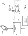
- FIG. 4 illustrates a schematic block diagram of an exemplary embodiment of welding system 400 including welding circuit path 405 .
- welding system 400 is also referred to as the welding work cell, wherein the welding work cell and/or welding system 400 can produce welds or welded parts.
- Welding system 400 includes welder power source 410 and display 415 operationally connected to welder power source 410 .
- display 415 may be an integral part of welder power source 410 .
- display 415 can be incorporated into welder power source 410 , a stand-alone component (as depicted), or a combination thereof.
- Welding system 100 further includes welding cable 120 , welding tool 430 , workpiece connector 450 , spool of wire 460 , wire feeder 470 , wire 480 , and workpiece 440 .
- Wire 480 is fed into welding tool 430 from spool 460 via wire feeder 470 , in accordance with an embodiment of the present invention.
- welding system 400 does not include spool of wire 460 , wire feeder 470 , or wire 480 but, instead, includes a welding tool comprising a consumable electrode such as used in, for example, stick welding.
- welding tool 430 may include at least one of a welding torch, a welding gun, and a welding consumable.
- Welding circuit path 405 runs from welder power source 410 through welding cable 420 to welding tool 430 , through workpiece 440 and/or to workpiece connector 450 , and back through welding cable 420 to welder power source 110 .
- electrical current runs through welding circuit path 405 as a voltage is applied to welding circuit path 405 .
- welding cable 420 comprises a coaxial cable assembly.
- welding cable 420 comprises a first cable length running from welder power source 410 to welding tool 430 , and a second cable length running from workpiece connector 450 to welder power source 410 .
- Welding system 400 includes welding job sequencer component 302 (as described above).
- Welding job sequencer component 302 is configured to interact with a portion of welding system 400 .
- welding job sequencer component 302 can interact with at least the power source 410 , a portion of welding circuit path 405 , spool of wire 460 , wire feeder 470 , or a combination thereof.
- Welding job sequencer component 302 automatically adjusts one or more elements of welding system 400 based on a welding sequence, wherein the welding sequence is utilized to configure welding system 400 (or an element thereof) without operator intervention in order to perform two or more welding procedures with respective settings or configurations for each welding procedure.
- welding job sequencer component 302 employs a welding sequence to automatically configure welding equipment.
- welding system 400 or welding work cell can employ a plurality of welding sequences for assembly of one or more workpieces.
- a workpiece can include three (3) welds to complete assembly in which a first welding sequence can be used for the first weld, a second welding sequence can be used for the second weld, and a third welding sequence can be used for the third weld.
- the entire assembly of the workpiece including the three (3) welds can be referenced as a welding sequence.
- a welding sequence that includes specific configurations or steps can further be included within a disparate welding sequence (e.g., nested welding sequence).
- a nested welding sequence can be a welding sequence that includes a welding sequence as part of the procedure.
- the welding sequence can include at least one of a parameter, a welding schedule, a portion of a welding schedule, a step-by-step instruction, a portion of media (e.g., images, video, text, and the like), a tutorial, among others.
- the welding sequence can be created and employed in order to guide an operator through welding procedure(s) for specific workpieces without the operator manually setting welding equipment to perform such welding procedures.
- the subject innovation relates to creating a welding sequence and/or modifying a welding sequence.
- welder power source(s) aggregates data respective to a respective welding process to which the welder power source is providing power to implement. Such collected data relates to each welder power source and is herein referred to as “weld data.”
- Weld data can include welding parameters and/or information specific to the particular welding process the welder power source is supplying power.
- weld data can be an output (e.g., a waveform, a signature, a voltage, a current, among others), a weld time, a power consumption, a welding parameter for a welding process, a welder power source output for the welding process, and the like.
- weld data can be utilized with welding job sequencer component 302 .
- weld data can be set by a welding sequence.
- weld data can be used as a feedback or a feedforward loop to verify settings.
- welding job sequencer component 302 is a computer operable to execute the disclosed methodologies and processes, including methods 1100 and 1200 described herein.
- the following discussion is intended to provide a brief, general description of a suitable computing environment in which the various aspects of the present invention may be implemented. While the invention has been described above in the general context of computer-executable instructions that may run on one or more computers, those skilled in the art will recognize that the invention also may be implemented in combination with other program modules and/or as a combination of hardware and/or software.
- program modules include routines, programs, components, data structures, etc., that perform particular tasks or implement particular abstract data types.
- inventive methods may be practiced with other computer system configurations, including single-processor or multiprocessor computer systems, minicomputers, mainframe computers, as well as personal computers, hand-held computing devices, microprocessor-based or programmable consumer electronics, and the like, each of which may be operatively coupled to one or more associated devices.
- the illustrated aspects of the invention may also be practiced in distributed computing environments where certain tasks are performed by remote processing devices that are linked through a communications network.
- program modules may be located in both local and remote memory storage devices. For instance, a remote database, a local database, a cloud-computing platform, a cloud database, or a combination thereof can be utilized with welding job sequencer 302 .
- Welding job sequencer 302 can utilize an exemplary environment for implementing various aspects of the invention including a computer, wherein the computer includes a processing unit, a system memory and a system bus.
- the system bus couples system components including, but not limited to the system memory to the processing unit.
- the processing unit may be any of various commercially available processors. Dual microprocessors and other multi-processor architectures also can be employed as the processing unit.
- the system bus can be any of several types of bus structure including a memory bus or memory controller, a peripheral bus and a local bus using any of a variety of commercially available bus architectures.
- the system memory can include read only memory (ROM) and random access memory (RAM).
- ROM read only memory
- RAM random access memory
- Welding job sequencer 302 can further include a hard disk drive, a magnetic disk drive, e.g., to read from or write to a removable disk, and an optical disk drive, e.g., for reading a CD-ROM disk or to read from or write to other optical media.
- Welding job sequencer 302 can include at least some form of computer readable media.
- Computer readable media can be any available media that can be accessed by the computer.
- Computer readable media may comprise computer storage media and communication media.
- Computer storage media includes volatile and nonvolatile, removable and non-removable media implemented in any method or technology for storage of information such as computer readable instructions, data structures, program modules or other data.
- Computer storage media includes, but is not limited to, RAM, ROM, EEPROM, flash memory or other memory technology, CD-ROM, digital versatile disks (DVD) or other magnetic storage devices, or any other medium which can be used to store the desired information and which can be accessed by welding job sequencer 302 .
- Communication media typically embodies computer readable instructions, data structures, program modules or other data in a modulated data signal such as a carrier wave or other transport mechanism and includes any information delivery media.
- modulated data signal means a signal that has one or more of its characteristics set or changed in such a manner as to encode information in the signal.
- communication media includes wired media such as a wired network or direct-wired connection, and wireless media such as acoustic, Radio Frequency (RF), Near Field Communications (NFC), Radio Frequency Identification (RFID), infrared, and/or other wireless media. Combinations of any of the above should also be included within the scope of computer readable media.
- a number of program modules may be stored in the drives and RAM, including an operating system, one or more application programs, other program modules, and program data.
- the operating system in welding job sequencer 302 can be any of a number of commercially available operating systems.
- a user may enter commands and information into the computer through a keyboard and a pointing device, such as a mouse.
- Other input devices may include a microphone, an IR remote control, a track ball, a pen input device, a joystick, a game pad, a digitizing tablet, a satellite dish, a scanner, or the like.
- serial port interface that is coupled to the system bus, but may be connected by other interfaces, such as a parallel port, a game port, a universal serial bus (“USB”), an IR interface, and/or various wireless technologies.
- a monitor e.g., display 415
- a video adapter may also be connected to the system bus via an interface, such as a video adapter.
- Visual output may also be accomplished through a remote display network protocol such as Remote Desktop Protocol, VNC, X-Window System, etc.
- a computer typically includes other peripheral output devices, such as speakers, printers, etc.
- a display (in addition or in combination with display 415 ) can be employed with welding job sequencer 302 to present data that is electronically received from the processing unit.
- the display can be an LCD, plasma, CRT, etc. monitor that presents data electronically.
- the display can present received data in a hard copy format such as a printer, facsimile, plotter etc.
- the display can present data in any color and can receive data from welding job sequencer 302 via any wireless or hard wire protocol and/or standard.
- welding job sequencer 302 and/or system 400 can be utilized with a mobile device such as a cellular phone, a smart phone, a tablet, a portable gaming device, a portable Internet browsing device, a Wi-Fi device, a Portable Digital Assistant (PDA), among others.
- a mobile device such as a cellular phone, a smart phone, a tablet, a portable gaming device, a portable Internet browsing device, a Wi-Fi device, a Portable Digital Assistant (PDA), among others.
- PDA Portable Digital Assistant
- the computer can operate in a networked environment using logical and/or physical connections to one or more remote computers, such as a remote computer(s).
- the remote computer(s) can be a workstation, a server computer, a router, a personal computer, microprocessor based entertainment appliance, a peer device or other common network node, and typically includes many or all of the elements described relative to the computer.
- the logical connections depicted include a local area network (LAN) and a wide area network (WAN).
- LAN local area network
- WAN wide area network
- the computer When used in a LAN networking environment, the computer is connected to the local network through a network interface or adapter. When used in a WAN networking environment, the computer typically includes a modem, or is connected to a communications server on the LAN, or has other means for establishing communications over the WAN, such as the Internet. In a networked environment, program modules depicted relative to the computer, or portions thereof, may be stored in the remote memory storage device. It will be appreciated that network connections described herein are exemplary and other means of establishing a communications link between the computers may be used.
- a local or cloud (e.g., local, cloud, remote, among others) computing platform can be utilized for data aggregation, processing, and delivery.
- the cloud computing platform can include a plurality of processors, memory, and servers in a particular remote location.
- SaaS software-as-a-service
- a single application is employed by a plurality of users to access data resident in the cloud. In this manner, processing requirements at a local level are mitigated as data processing is generally done in the cloud, thereby relieving user network resources.
- the software-as-a-service application allows users to log into a web-based service (e.g., via a web browser) which hosts all the programs resident in the cloud.
- system 500 illustrates a welding environment with a plurality of welding work cells via a local, remote, or cloud database.
- System 500 includes a plurality of welding work cells such as first welding work cell 515 , second welding work cell 520 to Nth welding work cell 530 , where N is a positive integer.
- each welding work cell includes a welding job sequencer component 535 , 540 , and 545 , that is used to implement a welding schedule(s) to each welding work cell as well as or in the alternative to an enterprise-wide welding operation(s) and/or enterprise-wide welding work cell.
- Welding sequence(s) from each welding job sequencer component 535 , 540 , and 545 is received from the local or cloud database (e.g., local database, cloud database, remote database, among others) computing platform 510 .
- the local or cloud database e.g., local database, cloud database, remote database, among others
- each welding work cell further includes a local data store.
- first welding work cell 515 includes welding job sequencer component 535 and data store 550
- second welding work cell 520 includes welding job sequencer component 540 and data store 555
- Nth welding work cell 530 includes welding job sequencer component 545 and data store 560 .
- system 500 includes welding job sequencer 302 hosted by computing platform 510 in which each welding work cell includes a distributed and respective welding job sequencer component.
- welding job sequencer 302 (and distributed welding job sequencer components 535 , 540 , and 545 ) can be a stand-alone component in each welding work cell or a stand-alone component in the computing platform 510 .
- Each welding work cell can include a respective data store that stores a portion of at least one welding sequence. For instance, welding sequences related to a welding process A is employed at one or more welding work cell. The welding sequence is stored in a respective local data store (e.g., data stores 550 , 555 , and 560 ). Yet, it is to be appreciated and understood that each welding work cell can include a local data store (as depicted), a collective and shared remote data store, a collective and shared local data store, a cloud data store hosted by computing platform 510 , or a combination thereof.
- a “data store” or “memory” can be, for example, either volatile memory or nonvolatile memory, or can include both volatile and nonvolatile memory.
- the data store of the subject systems and methods is intended to comprise, without being limited to, these and other suitable types of memory.
- the data store can be a server, a database, a hard drive, a flash drive, an external hard drive, a portable hard drive, a cloud-based storage, and the like.
- welding job sequencer component 302 can manage each welding job sequencer component 535 , 540 , 545 in each welding work cell 515 , 520 , 530 .
- the communications can be transmitted from the welding job sequencer 302 to each welding work cell (e.g., each welding job sequencer component).
- the communications can be received from each welding work cell (e.g., each welding job sequencer component) from the welding job sequencer component 302 .
- a welding sequence can be used with 1 st welding work cell 515 and communicated directly to a disparate welding work cell or via computing platform 510 .
- FIG. 6 illustrates welding system 600 that includes a plurality of welding work cells in which welding job sequencer component 302 is hosted with computing platform 510 to utilize one or more welding sequences to configure welding equipment within one or more welding systems, welding environments, and/or welding work cells.
- Welding system 600 includes a local or cloud-based welding job sequencer component 302 hosted in computing platform 510 .
- Welding job sequencer component 302 can utilize a welding sequence with a number of welding work cell.
- welding system 600 can a number of welding work cells such as, but not limited to, 1 st welding work cell 620 , 2 nd welding work cell 630 , to Nth welding work cell, where N is a positive integer.
- the locality of the welding job sequencer component 302 is in relation to each 1 st welding work cell 620 , 2 nd welding work cell 630 , and/or Nth welding work cell 640 .
- welding job sequencer 302 communicates one or more welding sequence to a target welding work cell, wherein the target welding work cell is a welding work cell that is to utilize the communicated welding sequence. Yet, in another embodiment, welding job sequencer 302 utilizes memory 650 hosted by computing platform 510 in which one or more welding sequences are stored. Yet, the stored welding sequence can be related or targeted to one or more welding work cells regardless of a storage location (e.g., local, cloud, remote, among others).
- a storage location e.g., local, cloud, remote, among others.
- FIG. 7 illustrates system 700 that generates a welding sequence based on welding procedure data.
- System 700 includes collect component 702 that is configured to receive a portion of welding procedure data to create welding sequence 706 .
- Collect component 702 receives, collects, aggregates, and/or identifies a portion of welding procedure data in which generate component 704 utilizes to create welding sequence 706 .
- welding sequence 706 is used by a welding job sequencer component (See FIGS. 3-6 ) to perform two or more welds with two or more respective welding parameters (e.g., welding schedules, parameters, configurations, settings, and the like).
- welding sequence 706 is employed to automatically configure welding equipment without operator intervention to perform a first welding operation with a first welding schedule and a second welding operation with a second welding schedule.
- the portion of welding procedure data is related to at least one of a performed welding process or procedure, or a welding process or procedure that has been performed.
- a portion of welding procedure data is data based upon a real world welding operation (e.g., real time weld being performed and data collected therefrom, previously collected data from a weld performed, among others).
- welding procedure data can be at least one of welding parameters, settings (e.g., voltage, current, and the like), monitored readings (e.g., measured current, measure voltage, and the like), welding equipment configurations (e.g., power source settings, waveforms, wire feed speed, and the like), welder setup (e.g., workpiece type, wire type, material type, weld to perform, and the like), among others.
- welding procedure data can be any data collected or monitored from a weld or welding equipment during the actual weld being performed or created.
- system 700 can be a stand-alone system (as depicted), incorporated into welding job sequencer component (not shown), or a combination thereof.
- welding procedure data can be received via welding job sequencer and thus from a local data store, a remote data store, a cloud-based data store, a computing platform, and/or any other network or computing environment configuration discussed above in regards to the welding job sequencer.
- a welding environment A can collect welding procedure data or parameters in which such welding procedure data is communicated (e.g., via Internet, cloud, computing platform, among others) to welding environment B.
- Welding environment B can utilize the welding procedure data from environment A to create a welding sequence for welding environment B based on a correlation or matched parameter for the welding procedure to perform.
- real world weld data or real world welding procedure data can be utilized by generate component 704 to create welding sequence 706 independent of a welding environment to which welding procedure data originates.
- welding procedure data can be collected from one or more welding operations, welding equipment, welding environments, welding work cells, and the like. Based on the collected welding procedure data, generate component 704 can further be configured to identify one or more parameters to use as welding sequence 706 .
- a computer-based evaluation can be utilized to determine which collected welding procedure data provides desired results.
- an operator or user can evaluate collected welding procedure data to select which welding procedure data provides a desired result.
- a cloud-based platform or computing platform can be employed to collect welding procedure data used to generate welding sequence(s) 706 .
- a welding sequence can include a replenishment of a consumable.
- the welding sequence can be created or edited to include a replenishment of a consumable for at least one of a welding work cell, a welding equipment, among others.
- a replenishment of a consumable can be included with a welding sequence after a period of time, wherein the period of time is estimated based on the duration the welding equipment is used (e.g., estimate the use of consumables).
- a welding environment, welding system, and/or welding work cell can be evaluated in real time or from collected real time data and identify data to determine a replenishment of a consumable.
- a welding sequence can include an inspection or a repair.
- the welding sequence can be created or edited to include an inspection request or a repair request based on a factor such as, but not limited to, a time, a duration, among others.
- a welding work cell can have a maintenance period for a particular time and if a welding sequence is created for such welding work cell, a repair or maintenance can be included with the created welding sequence.
- a welding environment, welding system, and/or welding work cell can be evaluated in real time or from collected real time data and identify data to determine inspections or repairs.
- collect component 702 can be a stand-alone component (as depicted), incorporated into generate component 704 , incorporated into the welding job sequencer component (not shown), or a combination thereof.
- generate component 704 can be a stand-alone component (as depicted), incorporated into collect component 702 , incorporated into the welding job sequencer component (not shown), or a combination thereof.
- FIG. 8 illustrates system 800 that creates a welding sequence from an operator performing a weld with welding equipment on a workpiece.
- System 800 further includes train component 802 that is configured to receive a live feed (e.g., real time capture) of a welding procedure and/or creation of a weld.
- Train component 802 enables operator 804 to input welding procedure data to create a welding sequence in which the input is the operator physically performing the weld and/or welding procedure from which to create a welding sequence.
- train component 802 allows operator 804 to perform a weld (e.g., create the weld with welding equipment 806 on workpiece 808 ) rather than providing welding procedure data.
- system 800 and/or train component 802 can create a welding sequence based upon at least one of welding procedure data, physically performed weld creation (via train component 802 ), or a combination thereof.
- the training for a welding sequence can be based on an operator or a machine performed weld or welding procedure.
- the monitoring of the operator or the machine performed weld or welding procedure can be recorded with, for instance, a video camera, a camera, a data collector (e.g., collecting settings, voltage, current, materials used, welding equipment settings, and the like), among others.
- a data collector e.g., collecting settings, voltage, current, materials used, welding equipment settings, and the like
- an embodiment can include a snapshot of settings for welding equipment 806 to base a creation of a welding sequence. With the settings of welding equipment 806 established, the welding sequence can be utilized to automatically configure one or more welding equipment 806 to perform two or more welds without user intervention.
- Train component 802 is further configured to record data related to a welding procedure from which a welding sequence is to be created or originate. For instance, welding characteristics (e.g., voltage, current, wire feed speed, settings for welding equipment, among others) can be collected related to the welding operation being performed. Additionally or in the alternative, data related to the act of performing the welding procedure can be captured as well. As will be discussed in more detail below, data related to the act of performing the welding procedure can include media (e.g., video, images, audio, among others) of the operator and/or machine performing the welding procedure.
- media e.g., video, images, audio, among others
- a user can perform a physical weld and approve or reject whether the physical weld performed (and welding procedure data related thereto) is to be used by generate component 704 to create the welding sequence. If approved, the data collected from the real time physical weld via train component 802 is used to create the welding sequence. If rejected, the data collected is not used to create a welding sequence.
- an average of data collected during training can be employed. For instance, train component 802 can monitor, track, and/or collect real time data during physical training of weld creation for a specified number of welds. During such training, an average of the collected or tracked data can be used to create settings or configurations used with a created welding sequence. Thus, monitoring or tracking more than one physical creation of a weld or welding process can provide more accurate data to be used to generate a welding sequence.
- welds and/or welding procedures can be stored in a data store (discussed in more detail below).
- characteristics e.g., weld type, material, workpiece, type of welding equipment, wire feed speed, wire gauge, time, pace, among others
- characteristics e.g., weld type, material, workpiece, type of welding equipment, wire feed speed, wire gauge, time, pace, among others
- individual weld data welding procedure data for a single weld
- a best individual weld data tracked can replace existing data with the welding sequence (e.g., based upon performance analysis, among others).
- FIG. 9 illustrates system 900 that creates a welding sequence for employment in a welding environment.
- System 900 includes media component 902 that is configured to include media to a welding sequence.
- media can be, but is not limited to being, photos, images, graphics, text, audio, video, computer generated imagery, animations, dictations, voice recordings, and the like.
- media component 902 includes media to facilitate performing a weld or welding operation from an operator perspective.
- media component 902 includes a video of a weld being created (e.g., via train component above) for the welding sequence.
- the video can guide an operator on how to perform the weld.
- media component 902 provides media related to at least one of safety concerns for utilizing the welding procedure, areas of caution, problematic situations, warnings, potential mistakes, scores, time, date, ranking of welding performed, among others.
- Media component 902 includes data with the welding sequence that can be displayed, communicated, or output to the operator, a location where the welding sequence is used, within a welding work cell, a welding environment, and the like.
- System 900 further includes identification component 904 that is configured to aggregate data for specification of the created welding sequence.
- Identification component 904 associates data to a welding sequence during or after creation, wherein the data can specify such welding sequence.
- the data can relate to date, time, user identification of who created, user identification of who modified, welding job, client, workpiece information, welding information (e.g., welding parameters, welding equipment settings, and the like), environment data (e.g., welding environment that welding sequence will be used, target welding equipment, and the like), job information (e.g., work order, client, work instructions, and the like), among others.
- Identification component 904 is customizable to include data to locate and employ a welding sequence via search and/or query based on a criteria defined or included with a welding sequence.
- a job-based criteria can be employed in which job related data is aggregated for a created welding sequence and associated therewith.
- a query discussed in more detail below
- job-based data can be utilized to locate and find the welding sequence. It is to be appreciated that various data can be collected and associated with a created welding sequence at various points of creation and that any suitable data can be collected at any suitable point during the creation of a welding sequence.
- identification component 904 can collect an employee identification of a creator of a welding sequence.
- the employee identification can be related to a creator of the welding sequence, an actor of performing a welding procedure (e.g., via train component discussed above), an editor of a welding sequence, among others.
- identification component 904 can associate one or more employee identifications to a welding sequence to provide a tracking of each welding sequence creation, edit, and/or modification of a welding sequence.
- This employee identification information can be used to provide query results for one or more creators (e.g., employees, workers, users, and the like).
- identification component 904 can collect data for a portion of a welding sequence to enable portions or parts of a welding sequence to be identified or located. This, for instance, can allow a user to identify a part or portion of a welding sequence to reuse in a creation of another welding sequence.
- System 900 further includes communication component 906 that is configured to transmit and/or receive at least a portion of a welding sequence.
- communication component 906 can transmit a portion of a welding sequence from a first location to a second location.
- a welding sequence can be communicated from a welding work cell to a disparate welding work cell, a welding environment to a disparate welding environment, an operator to a disparate operator, among others.
- communication component 906 is further configured to print data related to the welding sequence, wherein the data is at least one of work instructions, related media, client information, welding parameters, welding equipment settings, details of the welding sequence, among others.
- FIG. 10 illustrates system 1000 that utilizes a welding sequence for automatic configuration of a welding system to perform two or more welds.
- System 1000 includes query component 1002 that is configured to receive a query and provide a result based on the query.
- Query component 1002 can query one or more data stores discussed above.
- query component 1002 can query data stored with welding sequence data store 1004 .
- Welding sequence data store 1004 stores at least one of a welding sequence, a portion of a welding sequence, and/or data (e.g., metadata, metadata tags, and the like) associated with a welding sequence.
- Query component 1002 based on a received query, can generate results from at least welding sequence data store 1004 .
- Query component 1002 and welding sequence data store 1004 facilitate creating welding sequences (e.g., by allowing reuse of portions of a welding sequence), management of welding sequences, and locating welding sequences (e.g., updating, synchronizing, consistency, among others). As discussed above, query component 1002 can leverage data collected via identification component (See FIG. 9 ).
- query component 1002 is further configured to match a welding sequence based on a received query or data. For instance, a query requesting a welding sequence related to a particular parameter can be received by query component 1002 in which a welding sequence matching or including the particular parameter is returned.
- a welding procedure can be monitored in real time to collect real time parameters (e.g., welding procedure data) and the query component 1002 can identify a welding sequence that matches or includes a portion of the welding procedure data. Utilizing the matched welding sequence, welding equipment and/or operator(s) can be guided through the previously monitored welding procedure. For instance, a well-experienced operator can be monitored and subsequently (after the welding procedure is created or matched) a less experienced operator and/or equipment can be guided and/or configured.
- System 1000 further includes update component 1006 that is configured to modify a previously created welding sequence.
- Update component 1006 modifies an existing welding sequence with new (e.g., non-existing data) or edited (e.g., previously existing data) information. It is to be appreciated that update component 1006 can create a new welding sequence that includes modified data and archive the previous welding sequence. In another embodiment, update component 1006 can replace the new welding sequence with modified data in place of the previous welding sequence. Moreover, it is to be appreciated that update component 1006 can be utilized with query component 1002 , welding sequence data store 1004 , and/or identification component (See FIG. 9 ).
- a user can utilize query component 1002 to identify a previously created welding sequence in order to update the welding sequence with an updated media.
- query component 1002 Once identified via query component 1002 in welding sequence data store 1004 with identification component, the user or operator can add or replace media with the welding sequence to provide up-to-date specifications.
- a data model and/or software model can be employed to manage factors of the welding procedure used for the welding procedure.
- the software model and/or data model evaluates welding procedures performed with a corresponding welding sequence from which factors can be adjusted. For instance, a cycle time and/or a progression for a welding procedure can be adjusted based upon at least one of a software model and/or a data model.
- a first input can be received prior to a second input (as described below).
- a second input can be received prior to a first input.
- the a first input and a second input can be received at substantially the same time.
- not all illustrated blocks may be required to implement the methods and/or flow diagrams described hereinafter.
- Methodology 1100 evaluates one or more parameters related to a welding procedure being performed or that has been performed.
- a first parameter is received in which the first parameter is related to a first welding schedule (reference block 1102 ).
- a second parameter is received in which the second parameter is related to a second welding schedule (reference block 1104 ). It is to be appreciated that the first parameter and/or the second parameter can be based upon at least one of a previously performed welding precedure or a welding procedure being performed (e.g., real time).
- a welding sequence is created based on the first parameter and the second parameter, wherein the welding sequence defines a first welding procedure that includes the first parameter to create a first weld on a workpiece and a second welding procedure that includes the second parameter to create a second weld on the workpiece (reference block 1106 ).
- the created welding sequence is stored remote from the welding work cell (reference block 1108 ).
- the welding sequence is stored on a disparate network than a network that hosts a portion of the welding work cell.
- the welding sequence can be stored locally in reference to the welding work cell (e.g., welding sequence stored on a same network as the welding work cell).
- the welding sequence is utilized to automatically modify a welding equipment within the welding work cell without intervention from an operator creating at least one of the first weld or the second weld (reference block 1110 ).
- Flow diagram 1200 relates to creating a welding sequence based on one or more parameters of a welding procedure being performed or that has been performed.
- a parameter is collected from a welding procedure in real time, wherein the parameter relates to a welding schedule (reference block 1202 ).
- a welding sequence is created for a welding work cell, wherein the welding sequence defines at least the parameter and the welding schedule for a first welding procedure to create a first weld on a workpiece and a second welding procedure to create a second weld on the workpiece (reference block 1204 ).
- the welding sequence is employed for the welding work cell to perform one or more welds to assemble the workpiece by automatically adjusting a setting on a welding equipment within the welding work cell (reference block 1206 ).
- welding equipment e.g., controller for a welder power source, wire feeder, welder power source, among others
- a step can include a respective setting or configuration for at least one welding equipment.
- a first workpiece can include steps A, B, C, and D based on welding parameters desired, the welding process used, and/or the workpiece.
- a second workpiece can include steps B, C, A, E, and F.
- the welding sequence can indicate at least one of the following: which steps to perform, redo a step, skip a step, pause a sequence of steps, among others.
- a controller e.g., or other suitable component
- the method can include modifying the created welding sequence to update at least a portion of the first welding schedule or the second welding schedule.
- the method can further include tracking a welding process in real time; collecting one or more parameters of the welding process in real time; and employing the one or more parameters collected as at least one of the first parameter or the second parameter.
- the creating the welding process further includes: evaluating at least one of the first parameter or the second parameter in comparison with a previously created welding sequence; identifying a correlation between the first parameter and the second parameter with a portion of at least one previously created welding sequence; and utilizing a portion of the previously created welding sequence to create the welding sequence.
- the method can include appending the welding sequence with media to aid in performing at least one of the first weld or the second weld, the media is at least one of a video or an image.
- a system can include a weld score component that is configured to evaluate at least one of the first weld or the second weld performed on the workpiece based upon at least one of an image of the first weld or the second weld or a user inspection.
- a system can include a check point component that is configured to monitor the creation of at least one of the first weld or the second weld in real time.
- the welding job sequencer component further instructs an operator of the welding work cell to assemble the workpiece with the first welding procedure and the second welding procedure having two separate welding schedules.
- a system can include a third component that is configured to receive real time data associated with a creation of a weld from an operator and to utilize the received real time data to create the welding sequence.
- a system can include a data store that stores at least one of the parameter, the work schedule, or the welding sequence; and a fourth component that is configured to generate a query result based on a received query, wherein the query result is a welding sequence originating from a previously performed welding procedure from the data store that satisfies the received query.
- a system can include a fifth component that is configured to append a portion of media to the welding sequence in which the media illustrates an instruction on performing the welding sequence on the workpiece.
- a system can include a sixth component that is configured to collect identification information for the welding sequence.
- the identification information is metadata related to at least one of a user that created the welding sequence, a weld type, a client name, a material of the workpiece, a date, a time, a location, a serial number, a price, a wire speed, an originating welding procedure that is a source for the welding sequence, or a wire type.
- the welding sequence includes a replenishment of a consumable based on real time data collected from the welding work cell to estimate a duration of time in which the replenishment is to be performed.
- the welding sequence includes at least one of a repair or a maintenance of welding equipment based on real time data collected from the welding work cell to estimate a duration of time in which the repair or maintenance is to be performed.
- the step is at least one of an inspection, a maintenance for a welding equipment, a refilling of a consumable used in the welder system, a preventative maintenance for a welding equipment, a media capture of the workpiece, or a media capture of an assembly of the workpiece.
- a system can include an seventh component that is configured to communicate a portion of the welding sequence.
- the seventh component is further configured to generate a work instruction for the welding sequence based upon the welding schedule.
Landscapes
- Engineering & Computer Science (AREA)
- Physics & Mathematics (AREA)
- Plasma & Fusion (AREA)
- Mechanical Engineering (AREA)
- Theoretical Computer Science (AREA)
- Geometry (AREA)
- Human Computer Interaction (AREA)
- Manufacturing & Machinery (AREA)
- General Physics & Mathematics (AREA)
- Automation & Control Theory (AREA)
- General Factory Administration (AREA)
Abstract
Description
Claims (20)
Priority Applications (9)
| Application Number | Priority Date | Filing Date | Title |
|---|---|---|---|
| US13/802,883 US10994357B2 (en) | 2006-12-20 | 2013-03-14 | System and method for creating or modifying a welding sequence |
| PCT/IB2014/000319 WO2014140743A1 (en) | 2013-03-14 | 2014-03-13 | Systems and method for creating or modifying a welding sequence |
| CN202110573480.0A CN113351962A (en) | 2013-03-14 | 2014-03-13 | System and method for creating or modifying a welding sequence |
| DE202014010601.0U DE202014010601U1 (en) | 2013-03-14 | 2014-03-13 | Systems for generating or modifying a welding sequence |
| CN201480026654.XA CN105209993B (en) | 2013-03-14 | 2014-03-13 | System and method for creating or changing welding sequences |
| CN201910567340.5A CN110216353B (en) | 2013-03-14 | 2014-03-13 | System and method for creating or modifying a welding sequence |
| CN201480026559.XA CN105229545A (en) | 2013-03-14 | 2014-03-13 | Systems and methods for creating or changing welding sequences |
| DE202014010631.2U DE202014010631U1 (en) | 2013-03-14 | 2014-03-13 | Systems for generating or modifying a welding sequence |
| PCT/IB2014/000326 WO2014140749A1 (en) | 2013-03-14 | 2014-03-13 | Systems and method for creating or modifying a welding sequence |
Applications Claiming Priority (2)
| Application Number | Priority Date | Filing Date | Title |
|---|---|---|---|
| US11/613,652 US9104195B2 (en) | 2006-12-20 | 2006-12-20 | Welding job sequencer |
| US13/802,883 US10994357B2 (en) | 2006-12-20 | 2013-03-14 | System and method for creating or modifying a welding sequence |
Related Parent Applications (1)
| Application Number | Title | Priority Date | Filing Date |
|---|---|---|---|
| US11/613,652 Continuation-In-Part US9104195B2 (en) | 2006-12-20 | 2006-12-20 | Welding job sequencer |
Publications (2)
| Publication Number | Publication Date |
|---|---|
| US20140263225A1 US20140263225A1 (en) | 2014-09-18 |
| US10994357B2 true US10994357B2 (en) | 2021-05-04 |
Family
ID=51522888
Family Applications (1)
| Application Number | Title | Priority Date | Filing Date |
|---|---|---|---|
| US13/802,883 Active 2029-10-21 US10994357B2 (en) | 2006-12-20 | 2013-03-14 | System and method for creating or modifying a welding sequence |
Country Status (1)
| Country | Link |
|---|---|
| US (1) | US10994357B2 (en) |
Cited By (1)
| Publication number | Priority date | Publication date | Assignee | Title |
|---|---|---|---|---|
| US20230294194A1 (en) * | 2020-05-26 | 2023-09-21 | Illinois Tool Works Inc. | Input power user interfaces for welding power supplies |
Families Citing this family (16)
| Publication number | Priority date | Publication date | Assignee | Title |
|---|---|---|---|---|
| US8546728B2 (en) | 2005-03-04 | 2013-10-01 | Illinois Tool Works Inc. | Welder with integrated wire feeder having single-knob control |
| US9937577B2 (en) | 2006-12-20 | 2018-04-10 | Lincoln Global, Inc. | System for a welding sequencer |
| US10994357B2 (en) | 2006-12-20 | 2021-05-04 | Lincoln Global, Inc. | System and method for creating or modifying a welding sequence |
| US10994358B2 (en) | 2006-12-20 | 2021-05-04 | Lincoln Global, Inc. | System and method for creating or modifying a welding sequence based on non-real world weld data |
| US9104195B2 (en) | 2006-12-20 | 2015-08-11 | Lincoln Global, Inc. | Welding job sequencer |
| US11072034B2 (en) | 2006-12-20 | 2021-07-27 | Lincoln Global, Inc. | System and method of exporting or using welding sequencer data for external systems |
| MX2013011068A (en) | 2011-03-25 | 2014-04-30 | Illinois Tool Works | Welding systems with means for adjust and displaying ranges of parameters for setting the latter; method of setting such welding parameters. |
| US11821053B2 (en) * | 2015-06-30 | 2023-11-21 | Magna International Inc. | System for conditioning material using a laser and method thereof |
| US10773328B2 (en) * | 2015-12-15 | 2020-09-15 | Illinois Tool Works Inc. | Welding system user interface having a color display for setting welding parameters |
| EP3319066A1 (en) | 2016-11-04 | 2018-05-09 | Lincoln Global, Inc. | Magnetic frequency selection for electromagnetic position tracking |
| JP7132761B2 (en) * | 2018-06-13 | 2022-09-07 | 株式会社トヨタプロダクションエンジニアリング | Motion segment creation device, motion segment creation method, and motion segment creation program |
| DE102019200520A1 (en) * | 2019-01-17 | 2020-07-23 | Robert Bosch Gmbh | WELDING SYSTEM AND METHOD FOR TRANSMITTING SPECIFIC DATA FOR PRODUCING A WELDING CONNECTION BETWEEN WELDING CONTROLS OF THE WELDING SYSTEM |
| US11806814B2 (en) | 2019-02-19 | 2023-11-07 | Illinois Tool Works Inc. | Welding location and order monitoring in welding systems |
| US11311958B1 (en) * | 2019-05-13 | 2022-04-26 | Airgas, Inc. | Digital welding and cutting efficiency analysis, process evaluation and response feedback system for process optimization |
| US12220774B2 (en) * | 2019-10-22 | 2025-02-11 | Illinois Tool Works Inc. | Systems and methods for multiple source control of an engine driven power system |
| US12530984B2 (en) | 2023-12-13 | 2026-01-20 | Illinois Tool Works Inc. | Welding systems with automatic welding instruction generation |
Citations (150)
| Publication number | Priority date | Publication date | Assignee | Title |
|---|---|---|---|---|
| US3581051A (en) | 1967-08-01 | 1971-05-25 | Nat Res Dev | Welding apparatus |
| US3689734A (en) | 1969-03-04 | 1972-09-05 | North American Rockwell | Programmed control system |
| US3847584A (en) | 1973-05-24 | 1974-11-12 | Ppg Industries Inc | Automatic variable phase shift control for welding glass sheets |
| US4104724A (en) | 1977-06-27 | 1978-08-01 | Square D Company | Digital welder control system |
| US4145593A (en) | 1976-02-03 | 1979-03-20 | Merrick Welding International, Inc. | Automatic pipe welding system |
| US4324973A (en) | 1980-11-21 | 1982-04-13 | United Technologies Corp. | Energy beam drilling apparatus having optical fiber link position sensor |
| US4380696A (en) | 1980-11-12 | 1983-04-19 | Unimation, Inc. | Method and apparatus for manipulator welding apparatus with vision correction for workpiece sensing |
| US4390954A (en) | 1981-04-13 | 1983-06-28 | Merrick Engineering, Inc. | Override control apparatus and method for parameter adjustment of digitally based welding process programmers |
| US4419562A (en) | 1982-01-19 | 1983-12-06 | Western Electric Co., Inc. | Nondestructive real-time method for monitoring the quality of a weld |
| US4419560A (en) | 1980-12-19 | 1983-12-06 | Midland-Ross Corporation | Welding control with automatic percent heat adjustment |
| US4459457A (en) | 1980-10-16 | 1984-07-10 | Square D Company | Feedback welder control system |
| US4477713A (en) | 1982-07-09 | 1984-10-16 | Crc Welding Systems, Inc. | Sidewall-matching adaptive control system for welding |
| US4497019A (en) | 1981-03-20 | 1985-01-29 | Gnb Batteries Inc. | Programmable control system for controlling at least two parameters in a predetermined sequence using both analog and digital control signals |
| US4527045A (en) | 1980-03-17 | 1985-07-02 | Hitachi Seiko Ltd. | Control apparatus for an arc welder |
| US4681999A (en) | 1984-06-20 | 1987-07-21 | Arturo Hruska | Apparatus for welding dental elements |
| US4785159A (en) | 1985-03-13 | 1988-11-15 | Titanweld B.V. | Dental welding device and system |
| US4881678A (en) | 1987-01-20 | 1989-11-21 | Framatome | Process for the remote-controlled semi-automatic welding of two rotationally symmetrical components |
| US4920248A (en) | 1987-01-23 | 1990-04-24 | Fanuc, Ltd. | ARC sensing welding apparatus controlled by program |
| US5081338A (en) | 1991-02-15 | 1992-01-14 | Unitek Equipment Inc. | Apparatus and method for monitoring weld quality |
| US5206474A (en) | 1989-06-14 | 1993-04-27 | Shin Meiwa Industry Co., Ltd. | Weld line profile control method |
| US5265787A (en) | 1992-03-25 | 1993-11-30 | Kabushiki Kaisha Meidensha | Welding management apparatus |
| US5278390A (en) | 1993-03-18 | 1994-01-11 | The Lincoln Electric Company | System and method for controlling a welding process for an arc welder |
| US5380978A (en) | 1991-07-12 | 1995-01-10 | Pryor; Timothy R. | Method and apparatus for assembly of car bodies and other 3-dimensional objects |
| US5493093A (en) | 1992-07-09 | 1996-02-20 | Cecil; Dimitrios G. | Computer-integrated multi-gun welding system |
| US5532452A (en) | 1993-08-05 | 1996-07-02 | Lechner; Manfred | Welding robot |
| CH688034A5 (en) | 1993-12-01 | 1997-04-30 | Fischer Georg Rohrleitung | Pipeline connector moulding containing resistance heating wires with electronic memory and radio transponder |
| US5651903A (en) | 1995-10-12 | 1997-07-29 | Trw Inc. | Method and apparatus for evaluating laser welding |
| US5708253A (en) | 1995-06-07 | 1998-01-13 | Hill Technical Services, Inc. | Apparatus and method for computerized interactive control, measurement and documentation of arc welding |
| US5773779A (en) | 1997-02-21 | 1998-06-30 | The Lincoln Electric Company | Method and system for welding railroad rails |
| US5859847A (en) | 1996-12-20 | 1999-01-12 | Square D Company | Common database system for a communication system |
| US5866866A (en) | 1995-09-20 | 1999-02-02 | Miyachi Technos Corporation | Inverter seam resistance welding electric power supply apparatus |
| US5877468A (en) | 1997-02-21 | 1999-03-02 | The Lincoln Electric Company | Method and system for welding railroad rails |
| US5906761A (en) | 1995-01-04 | 1999-05-25 | Gilliland; Malcolm T. | Method of determining weld path for a robot welder |
| US5910894A (en) | 1994-01-11 | 1999-06-08 | Sensor Adaptive Machines, Inc. | Sensor based assembly tooling improvements |
| US6023044A (en) | 1996-04-12 | 2000-02-08 | Fanuc Ltd. | Control method in multi-layer welding |
| US6063458A (en) | 1999-02-11 | 2000-05-16 | Infosight Corporation | Folded identification tags |
| US6087627A (en) | 1998-09-21 | 2000-07-11 | Lincoln Global, Inc. | Method of controlling a welding process and controller therefor |
| US6115273A (en) | 1998-07-09 | 2000-09-05 | Illinois Tool Works Inc. | Power converter with low loss switching |
| US6133545A (en) | 1998-05-27 | 2000-10-17 | Matsushita Electric Industrial Co., Ltd. | Welding robot |
| USRE36926E (en) | 1994-10-31 | 2000-10-31 | United Technologies Corporation | Welding control using fuzzy logic analysis of video imaged puddle dimensions |
| US6151640A (en) | 1998-01-23 | 2000-11-21 | Schneider Automation Inc. | Control I/O module having the ability to interchange bus protocols for bus networks independent of the control I/O module |
| EP1078707A1 (en) | 1999-08-26 | 2001-02-28 | Aro | Automatic selection method of welding sequences for a manual welding gun and mual welding gun used to carry out the method |
| US6236017B1 (en) | 1999-07-01 | 2001-05-22 | Bechtel Bwxt Idaho, Llc | Method and apparatus for assessing weld quality |
| US6278074B1 (en) | 2000-02-28 | 2001-08-21 | Lincoln Global, Inc. | Method and system for welding railroad rails |
| US6292715B1 (en) | 1998-10-27 | 2001-09-18 | Perry Investments, Inc. | Robotic process planning method and apparatus using templates |
| EP1170649A1 (en) | 1993-01-11 | 2002-01-09 | Sensor Adaptive Machines Incorporated | A reconfigurable assembly tooling system and a method for automated development of assembly processes |
| US6399912B1 (en) | 2000-04-25 | 2002-06-04 | Illinois Tool Works Inc. | Method and apparatus for submerged arc welding |
| US20020117487A1 (en) | 2001-02-28 | 2002-08-29 | General Electric Company | Long reach welding torch and method for selecting torch shape |
| US6444942B1 (en) | 1999-08-03 | 2002-09-03 | Nadex Co. Ltd | Welding control systems |
| CN1370654A (en) | 2001-02-20 | 2002-09-25 | Aro公司 | Method for automatically selecting welding sequence by manual electrode holders and manual electrode holders |
| WO2002086656A2 (en) | 2001-04-20 | 2002-10-31 | Lincoln Global, Inc. | System and method for managing welding consumables |
| US6492618B1 (en) | 2000-11-02 | 2002-12-10 | Tri Tool Inc. | Automatic weld head alignment and guidance system and method |
| US6548783B1 (en) | 2001-10-03 | 2003-04-15 | General Electric Company | Apparatus for electric arc overlay welding |
| US6583386B1 (en) * | 2000-12-14 | 2003-06-24 | Impact Engineering, Inc. | Method and system for weld monitoring and tracking |
| US6624388B1 (en) | 2001-01-25 | 2003-09-23 | The Lincoln Electric Company | System and method providing distributed welding architecture |
| US6636776B1 (en) | 2001-07-09 | 2003-10-21 | Lincoln Global, Inc. | System and method for managing welding procedures and welding resources |
| CN1469791A (en) | 2000-10-17 | 2004-01-21 | ��Ŧ�� | Method for controlling and/or regulating a welding process |
| US6700097B1 (en) | 2001-09-28 | 2004-03-02 | Lincoln Global, Inc. | Electric ARC welder and controller to design the waveform therefor |
| US6708385B1 (en) | 1954-07-28 | 2004-03-23 | Lemelson Medical, Education And Research Foundation, Lp | Flexible manufacturing systems and methods |
| US6710298B2 (en) | 2000-02-11 | 2004-03-23 | Ingemar Eriksson | Device for metal welding |
| US6717108B2 (en) | 2001-10-12 | 2004-04-06 | Lincoln Global, Inc. | Electric arc welder and method of designing waveforms therefor |
| US6734394B2 (en) | 2001-10-12 | 2004-05-11 | Lincoln Global, Inc. | Electric arc welder and controller to duplicate a known waveform thereof |
| US6747247B2 (en) | 2001-09-19 | 2004-06-08 | Illinois Tool Works Inc. | Welding-type power supply with a state-based controller |
| US20040122550A1 (en) * | 2002-12-23 | 2004-06-24 | Robert Klimko | System and method for determining weld procedures |
| US6822195B2 (en) | 2003-04-02 | 2004-11-23 | General Motors Corporation | Automated weld location system for vehicles |
| US20040232128A1 (en) | 2001-09-12 | 2004-11-25 | Franz Niedereder | Remote contoller and control unit for a welding device |
| US20040245227A1 (en) | 2001-07-26 | 2004-12-09 | Clive Grafton-Reed | System and method for delivering an energy beam to selected impinge points on a work piece |
| US6847922B1 (en) | 2000-01-06 | 2005-01-25 | General Motors Corporation | Method for computer-aided layout of manufacturing cells |
| US6847956B2 (en) | 2001-02-06 | 2005-01-25 | General Electric Company | System and method for determining specific requirements from general requirements documents |
| US20050127052A1 (en) | 2003-12-12 | 2005-06-16 | Spencer Mark S. | Near real time arc welding monitor |
| US20050149210A1 (en) | 2004-01-07 | 2005-07-07 | Britton David E. | Methods to support process quality and maintenance during control of an industrial process such as welding |
| US6924459B2 (en) | 2001-01-25 | 2005-08-02 | Lincoln Global, Inc. | System and method providing automated welding information exchange and replacement part order generation |
| WO2005084867A2 (en) | 2004-03-09 | 2005-09-15 | Fronius International Gmbh | Work clothes for welding work |
| US20060070987A1 (en) | 2004-09-30 | 2006-04-06 | Lincoln Global, Inc. | Monitoring device for welding wire supply |
| US7030334B1 (en) | 2005-03-18 | 2006-04-18 | Ford Global Technologies, Llc | Method of diagnosing degradation of a welding system |
| US7028882B2 (en) | 2004-02-02 | 2006-04-18 | General Electric Company | Process and apparatus for boiler tube panel welding and straightening |
| US7032814B2 (en) | 1999-06-21 | 2006-04-25 | Lincoln Global, Inc. | Coded welding consumable |
| US20060131291A1 (en) * | 2004-12-16 | 2006-06-22 | Kaufman Charles L | Method and system of welding with auto-determined startup parameters |
| US7072774B1 (en) | 2002-08-28 | 2006-07-04 | Lincoln Global, Inc. | System and method for determining and employing consumable use by electric arc welders |
| US20060178778A1 (en) | 2005-02-10 | 2006-08-10 | Fuhlbrigge Thomas A | Method and apparatus for developing a software program |
| US7102098B2 (en) | 2000-12-08 | 2006-09-05 | L'Air Liquide - Societe Anonyme a Directoire et Counseil de Surveillance pour l'Etude et l'Exploitataion des Procedes Georges Claude | Method and system for solving a problem arising during a welding operation or the like |
| EP1700667A1 (en) | 2005-03-09 | 2006-09-13 | Fanuc Ltd | Laser-welding teaching device and method |
| US20060207980A1 (en) | 2005-03-15 | 2006-09-21 | Lincoln Global, Inc. | Comprehensive identification and designation of welding procedures |
| US20060231539A1 (en) | 2005-04-19 | 2006-10-19 | Licoin Global, Inc. | Method for rating and/or ranking welding electrodes |
| WO2007009131A1 (en) | 2005-07-15 | 2007-01-25 | Fronius International Gmbh | Welding method and welding system with determination of the position of the welding torch |
| EP1750185A2 (en) | 2005-07-26 | 2007-02-07 | Rockwell Automation Technologies, Inc. | Automation system and method based on RFID data defining an operation on a product |
| US20070056942A1 (en) * | 2005-09-15 | 2007-03-15 | Lincoln Global, Inc. | Welding system sequence control apparatus |
| US20070080153A1 (en) | 2005-10-07 | 2007-04-12 | Bruce Albrecht | Wireless tracking and inventory monitoring for welding-type devices |
| US20070262065A1 (en) | 2006-05-09 | 2007-11-15 | Lincoln Global, Inc. | Touch screen waveform design apparatus for welders |
| WO2008031052A2 (en) | 2006-09-07 | 2008-03-13 | Illinois Tool Works Inc. | Wireless system control and inventory monitoring for welding-type devices |
| US7358458B2 (en) | 2005-01-25 | 2008-04-15 | Lincoln Global, Inc. | Methods and apparatus for tactile communication in an arc processing system |
| US20080149686A1 (en) | 2006-12-20 | 2008-06-26 | Lincoln Global, Inc. | Welding Job Sequencer |
| US20080158502A1 (en) | 2006-12-27 | 2008-07-03 | Illinois Tool Works Inc. | Voice control welding/cutting helmet functions and settings |
| US20080169277A1 (en) | 2007-01-16 | 2008-07-17 | Illinois Tool Works Inc. | Lighted welding torch |
| US20090094721A1 (en) | 2007-10-11 | 2009-04-16 | Illinois Tool Works Inc. | Automated sensitivity setting for an auto-darkening lens in a welding helmet |
| US7523069B1 (en) | 1999-11-05 | 2009-04-21 | Fronium International Gmbh | Assessing and/or determining of user authorizations using a transponder, a finger print recognition routine or the like |
| US20090107969A1 (en) * | 2007-10-31 | 2009-04-30 | Kabushiki Kaisha Kobe Seiko Sho (Kobe Steel, Ltd.) | Arc welding robot control system and method thereof |
| US7539603B2 (en) | 2005-08-30 | 2009-05-26 | Autodesk, Inc. | Detection of component hole gaps for weld beads in a computer-implemented solid modeling system |
| US20090173726A1 (en) * | 2008-01-09 | 2009-07-09 | Robert Raimund Davidson | Automatic Weld Arc Monitoring System |
| US7603191B2 (en) | 2005-02-16 | 2009-10-13 | Idealab | System and method for design of a component |
| US7617017B2 (en) | 2005-02-18 | 2009-11-10 | Gm Global Technology Operations, Inc. | System and method for resource reallocation based on ambient condition data |
| US20090277893A1 (en) | 2008-05-12 | 2009-11-12 | Brandon John Speilman | Welding power supply with scaled output voltage |
| US20090298024A1 (en) | 2008-05-28 | 2009-12-03 | Todd Batzler | Welding training system |
| US20090313549A1 (en) * | 2008-06-16 | 2009-12-17 | Bruce Alan Casner | Configurable welding interface for automated welding applications |
| US7642486B2 (en) | 2006-05-05 | 2010-01-05 | Illinois Tool Works Inc. | Welding device with arc termination control |
| US20100012625A1 (en) | 2006-10-20 | 2010-01-21 | Swagelok Company | Welding purge control using electronic flow control |
| US20100062405A1 (en) | 2008-08-21 | 2010-03-11 | Lincoln Global, Inc. | System and method providing arc welding training in a real-time simulated virtual reality environment using real-time weld puddle feedback |
| JP2010075954A (en) * | 2008-09-25 | 2010-04-08 | Daihen Corp | Welding robot |
| US20100176106A1 (en) | 2006-02-06 | 2010-07-15 | Kim Hardam Christensen | Carriage for Automating Welding, Brazing, Cutting and Surface Treatment Processes |
| US7772524B2 (en) | 2005-01-21 | 2010-08-10 | Lincoln Global, Inc. | Integrating sensors over a digital link |
| US20100217440A1 (en) * | 2009-02-24 | 2010-08-26 | Inspectech Corporation | Welding quality control and monitoring system |
| US7809534B2 (en) | 2007-09-28 | 2010-10-05 | Rockwell Automation Technologies, Inc. | Enhanced simulation models for automation |
| WO2010142858A1 (en) | 2009-06-12 | 2010-12-16 | Kemppi Oy | Welding optimisation |
| US20110083241A1 (en) | 2009-10-13 | 2011-04-14 | Lincoln Global, Inc. | Welding helmet with integral user interface |
| WO2011058433A1 (en) | 2009-11-13 | 2011-05-19 | Lincoln Global, Inc. | Method and apparatus for monitoring weld quality |
| US20110120978A1 (en) | 2009-11-26 | 2011-05-26 | Fanuc Corporation | Spot welding system |
| US20110172796A1 (en) | 2010-01-12 | 2011-07-14 | Ford Global Technologies, Llc | Weldability prediction and recommendation systems and methods |
| WO2011100214A1 (en) | 2010-02-12 | 2011-08-18 | Illinois Tool Works Inc. | Memory with weld bank data structure for welding applications; computerized welding system with such memory; method of storing welding data in a relational database in such memory |
| US20110246395A1 (en) | 2010-02-11 | 2011-10-06 | Illinois Tool Works Inc. | Method and Apparatus For Welding Cost Calculator |
| US20110255259A1 (en) | 2010-04-19 | 2011-10-20 | Trent Weber | Mounting structures for components in electronic devices |
| US20110290765A1 (en) | 2010-05-26 | 2011-12-01 | Illinois Tool Works Inc. | Automatic and semi-automatic welding systems and methods |
| WO2012004491A2 (en) | 2010-07-09 | 2012-01-12 | Renault S.A.S. | Method for inspecting the quality of a solder joint |
| US20120095941A1 (en) | 2010-02-11 | 2012-04-19 | Illinois Tool Works Inc. | Method and Apparatus For Welding Cost Calculator |
| CN202199978U (en) | 2011-08-16 | 2012-04-25 | 郑州贝龙液压技术有限公司 | Novel frame construction frock clamp |
| US20120122062A1 (en) | 2010-11-16 | 2012-05-17 | Electronics And Telecommunications Research Institute | Reconfigurable platform management apparatus for virtual reality-based training simulator |
| US20120145689A1 (en) | 2010-12-14 | 2012-06-14 | Lincoln Global, Inc. | Manual welding apparatus having an automatic wire retract method |
| US8224881B1 (en) | 2001-06-18 | 2012-07-17 | Lincoln Global, Inc. | System and method for managing welding information |
| US8322591B2 (en) | 2008-04-03 | 2012-12-04 | Caterpillar Inc. | Automated assembly and welding of structures |
| US20120325792A1 (en) | 2011-06-27 | 2012-12-27 | Illinois Tool Works Inc. | Workpiece-based setting of weld parameters |
| US20130008003A1 (en) | 2011-07-06 | 2013-01-10 | Kabushiki Kaisha Kobe Seiko Sho (Kobe Steel, Ltd.) | Welding tip replacement apparatus, welding tip replacement system, and method for replacing welding tip |
| US20130015169A1 (en) | 2011-07-15 | 2013-01-17 | Illinois Tool Works Inc. | Digital communication based arc control welding system and method |
| US20130075380A1 (en) | 2011-09-27 | 2013-03-28 | Illinois Tool Works Inc. | Welding system and method utilizing cloud computing and data storage |
| US20130119037A1 (en) | 2011-11-11 | 2013-05-16 | Lincoln Global, Inc. | Systems and methods for utilizing welder power source data |
| US20130264319A1 (en) | 2010-12-29 | 2013-10-10 | Illinois Tool Works, Inc. | Weld Cell System With Communication |
| US20130282182A1 (en) | 2012-04-23 | 2013-10-24 | Chrysler Group Llc | Method and system for scheduling weld events |
| US20130277344A1 (en) | 2011-10-13 | 2013-10-24 | Rimrock Automation, Inc. Dba Wolf Robotics | Robotic pre-heat and inter-pass welding |
| WO2013160745A1 (en) | 2012-04-23 | 2013-10-31 | Lincoln Global, Inc. | System and method for monitoring weld quality |
| US20140021184A1 (en) | 2012-07-18 | 2014-01-23 | Lincoln Global, Inc. | Automatic notification for consumable package replacement |
| US20140027422A1 (en) | 2012-07-27 | 2014-01-30 | Illinois Tool Works Inc. | Adaptable rotating arc welding method and system |
| US20140042137A1 (en) | 2006-12-20 | 2014-02-13 | Lincoln Global, Inc. | System and method of exporting or using welding sequencer data for external systems |
| US20140042136A1 (en) | 2006-12-20 | 2014-02-13 | Lincoln Global, Inc. | System and method of exporting or using welding sequencer data for external systems |
| US20140042135A1 (en) | 2006-12-20 | 2014-02-13 | Lincoln Global, Inc. | System and method of receiving or using data from external sources for a welding sequence |
| WO2014140743A1 (en) | 2013-03-14 | 2014-09-18 | Lincoln Global, Inc. | Systems and method for creating or modifying a welding sequence |
| WO2014140738A2 (en) | 2013-03-14 | 2014-09-18 | Lincoln Global, Inc. | Systems and methods of exporting or using welding sequencer data for external systems |
| WO2014140766A1 (en) | 2013-03-14 | 2014-09-18 | Lincoln Global, Inc. | System and method of receiving or using data from external sources for a welding sequence |
| WO2014140747A2 (en) | 2013-03-14 | 2014-09-18 | Lincoln Global, Inc. | Systems and methods of exporting or using welding sequencer data for external systems |
| US20140263226A1 (en) | 2006-12-20 | 2014-09-18 | Lincoln Global, Inc. | System and method for creating or modifying a welding sequence |
| WO2014140746A2 (en) | 2013-03-14 | 2014-09-18 | Lincoln Global, Inc. | System and method of receiving or using data from external sources for a welding sequence |
| US20140263225A1 (en) | 2006-12-20 | 2014-09-18 | Lincoln Global, Inc. | System and method for creating or modifying a welding sequence |
| US8884177B2 (en) | 2009-11-13 | 2014-11-11 | Lincoln Global, Inc. | Systems, methods, and apparatuses for monitoring weld quality |
Family Cites Families (1)
| Publication number | Priority date | Publication date | Assignee | Title |
|---|---|---|---|---|
| RU2007112675A (en) * | 2004-10-12 | 2008-11-20 | Ф.Хоффманн-Ля Рош Аг (Ch) | IMIDAZO [1,5-a] TRIAZOLO [1,5-d] BENZODIAZEPINE DERIVATIVES FOR THE TREATMENT OF COGNITIVE DISORDERS |
-
2013
- 2013-03-14 US US13/802,883 patent/US10994357B2/en active Active
Patent Citations (170)
| Publication number | Priority date | Publication date | Assignee | Title |
|---|---|---|---|---|
| US6708385B1 (en) | 1954-07-28 | 2004-03-23 | Lemelson Medical, Education And Research Foundation, Lp | Flexible manufacturing systems and methods |
| US3581051A (en) | 1967-08-01 | 1971-05-25 | Nat Res Dev | Welding apparatus |
| US3689734A (en) | 1969-03-04 | 1972-09-05 | North American Rockwell | Programmed control system |
| US3847584A (en) | 1973-05-24 | 1974-11-12 | Ppg Industries Inc | Automatic variable phase shift control for welding glass sheets |
| US4145593A (en) | 1976-02-03 | 1979-03-20 | Merrick Welding International, Inc. | Automatic pipe welding system |
| US4104724A (en) | 1977-06-27 | 1978-08-01 | Square D Company | Digital welder control system |
| US4527045A (en) | 1980-03-17 | 1985-07-02 | Hitachi Seiko Ltd. | Control apparatus for an arc welder |
| US4459457A (en) | 1980-10-16 | 1984-07-10 | Square D Company | Feedback welder control system |
| US4380696A (en) | 1980-11-12 | 1983-04-19 | Unimation, Inc. | Method and apparatus for manipulator welding apparatus with vision correction for workpiece sensing |
| US4324973A (en) | 1980-11-21 | 1982-04-13 | United Technologies Corp. | Energy beam drilling apparatus having optical fiber link position sensor |
| US4419560A (en) | 1980-12-19 | 1983-12-06 | Midland-Ross Corporation | Welding control with automatic percent heat adjustment |
| US4497019A (en) | 1981-03-20 | 1985-01-29 | Gnb Batteries Inc. | Programmable control system for controlling at least two parameters in a predetermined sequence using both analog and digital control signals |
| US4390954A (en) | 1981-04-13 | 1983-06-28 | Merrick Engineering, Inc. | Override control apparatus and method for parameter adjustment of digitally based welding process programmers |
| US4419562A (en) | 1982-01-19 | 1983-12-06 | Western Electric Co., Inc. | Nondestructive real-time method for monitoring the quality of a weld |
| US4477713A (en) | 1982-07-09 | 1984-10-16 | Crc Welding Systems, Inc. | Sidewall-matching adaptive control system for welding |
| US4681999A (en) | 1984-06-20 | 1987-07-21 | Arturo Hruska | Apparatus for welding dental elements |
| US4785159A (en) | 1985-03-13 | 1988-11-15 | Titanweld B.V. | Dental welding device and system |
| US4881678A (en) | 1987-01-20 | 1989-11-21 | Framatome | Process for the remote-controlled semi-automatic welding of two rotationally symmetrical components |
| US4920248A (en) | 1987-01-23 | 1990-04-24 | Fanuc, Ltd. | ARC sensing welding apparatus controlled by program |
| US5206474A (en) | 1989-06-14 | 1993-04-27 | Shin Meiwa Industry Co., Ltd. | Weld line profile control method |
| US5081338A (en) | 1991-02-15 | 1992-01-14 | Unitek Equipment Inc. | Apparatus and method for monitoring weld quality |
| US5380978A (en) | 1991-07-12 | 1995-01-10 | Pryor; Timothy R. | Method and apparatus for assembly of car bodies and other 3-dimensional objects |
| US5265787A (en) | 1992-03-25 | 1993-11-30 | Kabushiki Kaisha Meidensha | Welding management apparatus |
| US5493093A (en) | 1992-07-09 | 1996-02-20 | Cecil; Dimitrios G. | Computer-integrated multi-gun welding system |
| EP1170649A1 (en) | 1993-01-11 | 2002-01-09 | Sensor Adaptive Machines Incorporated | A reconfigurable assembly tooling system and a method for automated development of assembly processes |
| US5278390A (en) | 1993-03-18 | 1994-01-11 | The Lincoln Electric Company | System and method for controlling a welding process for an arc welder |
| US5532452A (en) | 1993-08-05 | 1996-07-02 | Lechner; Manfred | Welding robot |
| CH688034A5 (en) | 1993-12-01 | 1997-04-30 | Fischer Georg Rohrleitung | Pipeline connector moulding containing resistance heating wires with electronic memory and radio transponder |
| US5910894A (en) | 1994-01-11 | 1999-06-08 | Sensor Adaptive Machines, Inc. | Sensor based assembly tooling improvements |
| USRE36926E (en) | 1994-10-31 | 2000-10-31 | United Technologies Corporation | Welding control using fuzzy logic analysis of video imaged puddle dimensions |
| US5906761A (en) | 1995-01-04 | 1999-05-25 | Gilliland; Malcolm T. | Method of determining weld path for a robot welder |
| US5708253A (en) | 1995-06-07 | 1998-01-13 | Hill Technical Services, Inc. | Apparatus and method for computerized interactive control, measurement and documentation of arc welding |
| US5866866A (en) | 1995-09-20 | 1999-02-02 | Miyachi Technos Corporation | Inverter seam resistance welding electric power supply apparatus |
| US5651903A (en) | 1995-10-12 | 1997-07-29 | Trw Inc. | Method and apparatus for evaluating laser welding |
| US6023044A (en) | 1996-04-12 | 2000-02-08 | Fanuc Ltd. | Control method in multi-layer welding |
| US5859847A (en) | 1996-12-20 | 1999-01-12 | Square D Company | Common database system for a communication system |
| US5773779A (en) | 1997-02-21 | 1998-06-30 | The Lincoln Electric Company | Method and system for welding railroad rails |
| US5877468A (en) | 1997-02-21 | 1999-03-02 | The Lincoln Electric Company | Method and system for welding railroad rails |
| US6151640A (en) | 1998-01-23 | 2000-11-21 | Schneider Automation Inc. | Control I/O module having the ability to interchange bus protocols for bus networks independent of the control I/O module |
| US6133545A (en) | 1998-05-27 | 2000-10-17 | Matsushita Electric Industrial Co., Ltd. | Welding robot |
| US6115273A (en) | 1998-07-09 | 2000-09-05 | Illinois Tool Works Inc. | Power converter with low loss switching |
| US6087627A (en) | 1998-09-21 | 2000-07-11 | Lincoln Global, Inc. | Method of controlling a welding process and controller therefor |
| US6292715B1 (en) | 1998-10-27 | 2001-09-18 | Perry Investments, Inc. | Robotic process planning method and apparatus using templates |
| US6063458A (en) | 1999-02-11 | 2000-05-16 | Infosight Corporation | Folded identification tags |
| US7032814B2 (en) | 1999-06-21 | 2006-04-25 | Lincoln Global, Inc. | Coded welding consumable |
| US6236017B1 (en) | 1999-07-01 | 2001-05-22 | Bechtel Bwxt Idaho, Llc | Method and apparatus for assessing weld quality |
| US6444942B1 (en) | 1999-08-03 | 2002-09-03 | Nadex Co. Ltd | Welding control systems |
| EP1078707A1 (en) | 1999-08-26 | 2001-02-28 | Aro | Automatic selection method of welding sequences for a manual welding gun and mual welding gun used to carry out the method |
| US7523069B1 (en) | 1999-11-05 | 2009-04-21 | Fronium International Gmbh | Assessing and/or determining of user authorizations using a transponder, a finger print recognition routine or the like |
| US6847922B1 (en) | 2000-01-06 | 2005-01-25 | General Motors Corporation | Method for computer-aided layout of manufacturing cells |
| US6710298B2 (en) | 2000-02-11 | 2004-03-23 | Ingemar Eriksson | Device for metal welding |
| US6278074B1 (en) | 2000-02-28 | 2001-08-21 | Lincoln Global, Inc. | Method and system for welding railroad rails |
| US6399912B1 (en) | 2000-04-25 | 2002-06-04 | Illinois Tool Works Inc. | Method and apparatus for submerged arc welding |
| US6930280B2 (en) | 2000-10-17 | 2005-08-16 | Fronius International Gmbh | Method for the control and/or regulation of a welding process |
| CN1469791A (en) | 2000-10-17 | 2004-01-21 | ��Ŧ�� | Method for controlling and/or regulating a welding process |
| US6492618B1 (en) | 2000-11-02 | 2002-12-10 | Tri Tool Inc. | Automatic weld head alignment and guidance system and method |
| US7102098B2 (en) | 2000-12-08 | 2006-09-05 | L'Air Liquide - Societe Anonyme a Directoire et Counseil de Surveillance pour l'Etude et l'Exploitataion des Procedes Georges Claude | Method and system for solving a problem arising during a welding operation or the like |
| US6583386B1 (en) * | 2000-12-14 | 2003-06-24 | Impact Engineering, Inc. | Method and system for weld monitoring and tracking |
| US6624388B1 (en) | 2001-01-25 | 2003-09-23 | The Lincoln Electric Company | System and method providing distributed welding architecture |
| US6924459B2 (en) | 2001-01-25 | 2005-08-02 | Lincoln Global, Inc. | System and method providing automated welding information exchange and replacement part order generation |
| US6847956B2 (en) | 2001-02-06 | 2005-01-25 | General Electric Company | System and method for determining specific requirements from general requirements documents |
| CN1370654A (en) | 2001-02-20 | 2002-09-25 | Aro公司 | Method for automatically selecting welding sequence by manual electrode holders and manual electrode holders |
| US20020117487A1 (en) | 2001-02-28 | 2002-08-29 | General Electric Company | Long reach welding torch and method for selecting torch shape |
| US20100262468A1 (en) | 2001-04-20 | 2010-10-14 | Lincoln Global, Inc. | System and method for managing welding consumables |
| WO2002086656A2 (en) | 2001-04-20 | 2002-10-31 | Lincoln Global, Inc. | System and method for managing welding consumables |
| US8224881B1 (en) | 2001-06-18 | 2012-07-17 | Lincoln Global, Inc. | System and method for managing welding information |
| US6636776B1 (en) | 2001-07-09 | 2003-10-21 | Lincoln Global, Inc. | System and method for managing welding procedures and welding resources |
| US20040245227A1 (en) | 2001-07-26 | 2004-12-09 | Clive Grafton-Reed | System and method for delivering an energy beam to selected impinge points on a work piece |
| US20040232128A1 (en) | 2001-09-12 | 2004-11-25 | Franz Niedereder | Remote contoller and control unit for a welding device |
| US6747247B2 (en) | 2001-09-19 | 2004-06-08 | Illinois Tool Works Inc. | Welding-type power supply with a state-based controller |
| US6700097B1 (en) | 2001-09-28 | 2004-03-02 | Lincoln Global, Inc. | Electric ARC welder and controller to design the waveform therefor |
| US6548783B1 (en) | 2001-10-03 | 2003-04-15 | General Electric Company | Apparatus for electric arc overlay welding |
| US6734394B2 (en) | 2001-10-12 | 2004-05-11 | Lincoln Global, Inc. | Electric arc welder and controller to duplicate a known waveform thereof |
| US6717108B2 (en) | 2001-10-12 | 2004-04-06 | Lincoln Global, Inc. | Electric arc welder and method of designing waveforms therefor |
| US7072774B1 (en) | 2002-08-28 | 2006-07-04 | Lincoln Global, Inc. | System and method for determining and employing consumable use by electric arc welders |
| US8049139B2 (en) | 2002-08-28 | 2011-11-01 | Lincoln Global, Inc. | System and method for determining and employing consumable use by electric arc welders |
| US20040122550A1 (en) * | 2002-12-23 | 2004-06-24 | Robert Klimko | System and method for determining weld procedures |
| US6912447B2 (en) | 2002-12-23 | 2005-06-28 | Caterpillar Inc | System and method for determining weld procedures |
| US6822195B2 (en) | 2003-04-02 | 2004-11-23 | General Motors Corporation | Automated weld location system for vehicles |
| US20050127052A1 (en) | 2003-12-12 | 2005-06-16 | Spencer Mark S. | Near real time arc welding monitor |
| US20050149210A1 (en) | 2004-01-07 | 2005-07-07 | Britton David E. | Methods to support process quality and maintenance during control of an industrial process such as welding |
| US20070198105A1 (en) | 2004-01-07 | 2007-08-23 | Britton David R | Methods to support process quality and maintenance during control of an industrial process such as welding |
| US7028882B2 (en) | 2004-02-02 | 2006-04-18 | General Electric Company | Process and apparatus for boiler tube panel welding and straightening |
| WO2005084867A2 (en) | 2004-03-09 | 2005-09-15 | Fronius International Gmbh | Work clothes for welding work |
| US20060070987A1 (en) | 2004-09-30 | 2006-04-06 | Lincoln Global, Inc. | Monitoring device for welding wire supply |
| US20060131291A1 (en) * | 2004-12-16 | 2006-06-22 | Kaufman Charles L | Method and system of welding with auto-determined startup parameters |
| US7772524B2 (en) | 2005-01-21 | 2010-08-10 | Lincoln Global, Inc. | Integrating sensors over a digital link |
| US7358458B2 (en) | 2005-01-25 | 2008-04-15 | Lincoln Global, Inc. | Methods and apparatus for tactile communication in an arc processing system |
| US20060178778A1 (en) | 2005-02-10 | 2006-08-10 | Fuhlbrigge Thomas A | Method and apparatus for developing a software program |
| US7603191B2 (en) | 2005-02-16 | 2009-10-13 | Idealab | System and method for design of a component |
| US7617017B2 (en) | 2005-02-18 | 2009-11-10 | Gm Global Technology Operations, Inc. | System and method for resource reallocation based on ambient condition data |
| EP1700667A1 (en) | 2005-03-09 | 2006-09-13 | Fanuc Ltd | Laser-welding teaching device and method |
| US20060207980A1 (en) | 2005-03-15 | 2006-09-21 | Lincoln Global, Inc. | Comprehensive identification and designation of welding procedures |
| US8115138B2 (en) | 2005-03-15 | 2012-02-14 | Lincoln Global, Inc. | Comprehensive identification and designation of welding procedures |
| US7030334B1 (en) | 2005-03-18 | 2006-04-18 | Ford Global Technologies, Llc | Method of diagnosing degradation of a welding system |
| US20060231539A1 (en) | 2005-04-19 | 2006-10-19 | Licoin Global, Inc. | Method for rating and/or ranking welding electrodes |
| WO2007009131A1 (en) | 2005-07-15 | 2007-01-25 | Fronius International Gmbh | Welding method and welding system with determination of the position of the welding torch |
| EP1750185A2 (en) | 2005-07-26 | 2007-02-07 | Rockwell Automation Technologies, Inc. | Automation system and method based on RFID data defining an operation on a product |
| US7539603B2 (en) | 2005-08-30 | 2009-05-26 | Autodesk, Inc. | Detection of component hole gaps for weld beads in a computer-implemented solid modeling system |
| US20070056942A1 (en) * | 2005-09-15 | 2007-03-15 | Lincoln Global, Inc. | Welding system sequence control apparatus |
| US20070080153A1 (en) | 2005-10-07 | 2007-04-12 | Bruce Albrecht | Wireless tracking and inventory monitoring for welding-type devices |
| US20100176106A1 (en) | 2006-02-06 | 2010-07-15 | Kim Hardam Christensen | Carriage for Automating Welding, Brazing, Cutting and Surface Treatment Processes |
| US7642486B2 (en) | 2006-05-05 | 2010-01-05 | Illinois Tool Works Inc. | Welding device with arc termination control |
| US20070262065A1 (en) | 2006-05-09 | 2007-11-15 | Lincoln Global, Inc. | Touch screen waveform design apparatus for welders |
| WO2008031052A2 (en) | 2006-09-07 | 2008-03-13 | Illinois Tool Works Inc. | Wireless system control and inventory monitoring for welding-type devices |
| US20100012625A1 (en) | 2006-10-20 | 2010-01-21 | Swagelok Company | Welding purge control using electronic flow control |
| US9104195B2 (en) | 2006-12-20 | 2015-08-11 | Lincoln Global, Inc. | Welding job sequencer |
| WO2008079165A1 (en) | 2006-12-20 | 2008-07-03 | Lincoln Global, Inc. | Welding job sequencer |
| US20140042136A1 (en) | 2006-12-20 | 2014-02-13 | Lincoln Global, Inc. | System and method of exporting or using welding sequencer data for external systems |
| US20080149686A1 (en) | 2006-12-20 | 2008-06-26 | Lincoln Global, Inc. | Welding Job Sequencer |
| US20140042135A1 (en) | 2006-12-20 | 2014-02-13 | Lincoln Global, Inc. | System and method of receiving or using data from external sources for a welding sequence |
| US20140263226A1 (en) | 2006-12-20 | 2014-09-18 | Lincoln Global, Inc. | System and method for creating or modifying a welding sequence |
| US20140263225A1 (en) | 2006-12-20 | 2014-09-18 | Lincoln Global, Inc. | System and method for creating or modifying a welding sequence |
| CN101600532A (en) | 2006-12-20 | 2009-12-09 | 林肯环球股份有限公司 | Welding job sequencer |
| US20140042137A1 (en) | 2006-12-20 | 2014-02-13 | Lincoln Global, Inc. | System and method of exporting or using welding sequencer data for external systems |
| US20160361774A9 (en) | 2006-12-20 | 2016-12-15 | Lincoln Global, Inc. | System and method for creating or modifying a welding sequence |
| CN106270941A (en) | 2006-12-20 | 2017-01-04 | 林肯环球股份有限公司 | Welding Job Sequencer |
| US9937577B2 (en) | 2006-12-20 | 2018-04-10 | Lincoln Global, Inc. | System for a welding sequencer |
| US20080158502A1 (en) | 2006-12-27 | 2008-07-03 | Illinois Tool Works Inc. | Voice control welding/cutting helmet functions and settings |
| US20080169277A1 (en) | 2007-01-16 | 2008-07-17 | Illinois Tool Works Inc. | Lighted welding torch |
| US7809534B2 (en) | 2007-09-28 | 2010-10-05 | Rockwell Automation Technologies, Inc. | Enhanced simulation models for automation |
| US20090094721A1 (en) | 2007-10-11 | 2009-04-16 | Illinois Tool Works Inc. | Automated sensitivity setting for an auto-darkening lens in a welding helmet |
| US20090107969A1 (en) * | 2007-10-31 | 2009-04-30 | Kabushiki Kaisha Kobe Seiko Sho (Kobe Steel, Ltd.) | Arc welding robot control system and method thereof |
| US20090173726A1 (en) * | 2008-01-09 | 2009-07-09 | Robert Raimund Davidson | Automatic Weld Arc Monitoring System |
| US8322591B2 (en) | 2008-04-03 | 2012-12-04 | Caterpillar Inc. | Automated assembly and welding of structures |
| US20090277893A1 (en) | 2008-05-12 | 2009-11-12 | Brandon John Speilman | Welding power supply with scaled output voltage |
| US20090298024A1 (en) | 2008-05-28 | 2009-12-03 | Todd Batzler | Welding training system |
| US20090313549A1 (en) * | 2008-06-16 | 2009-12-17 | Bruce Alan Casner | Configurable welding interface for automated welding applications |
| US20100062405A1 (en) | 2008-08-21 | 2010-03-11 | Lincoln Global, Inc. | System and method providing arc welding training in a real-time simulated virtual reality environment using real-time weld puddle feedback |
| JP2010075954A (en) * | 2008-09-25 | 2010-04-08 | Daihen Corp | Welding robot |
| US20100217440A1 (en) * | 2009-02-24 | 2010-08-26 | Inspectech Corporation | Welding quality control and monitoring system |
| WO2010142858A1 (en) | 2009-06-12 | 2010-12-16 | Kemppi Oy | Welding optimisation |
| CN102573720A (en) | 2009-10-13 | 2012-07-11 | 林肯环球股份有限公司 | Welding helmet with integrated user interface |
| US20110083241A1 (en) | 2009-10-13 | 2011-04-14 | Lincoln Global, Inc. | Welding helmet with integral user interface |
| US8884177B2 (en) | 2009-11-13 | 2014-11-11 | Lincoln Global, Inc. | Systems, methods, and apparatuses for monitoring weld quality |
| US9089921B2 (en) | 2009-11-13 | 2015-07-28 | Lincoln Global, Inc. | Systems, methods, and apparatuses for monitoring weld quality |
| CN102596476A (en) | 2009-11-13 | 2012-07-18 | 林肯环球股份有限公司 | Method and apparatus for monitoring weld quality |
| WO2011058433A1 (en) | 2009-11-13 | 2011-05-19 | Lincoln Global, Inc. | Method and apparatus for monitoring weld quality |
| US20110120978A1 (en) | 2009-11-26 | 2011-05-26 | Fanuc Corporation | Spot welding system |
| US20110172796A1 (en) | 2010-01-12 | 2011-07-14 | Ford Global Technologies, Llc | Weldability prediction and recommendation systems and methods |
| US20120095941A1 (en) | 2010-02-11 | 2012-04-19 | Illinois Tool Works Inc. | Method and Apparatus For Welding Cost Calculator |
| US20110246395A1 (en) | 2010-02-11 | 2011-10-06 | Illinois Tool Works Inc. | Method and Apparatus For Welding Cost Calculator |
| US8592723B2 (en) | 2010-02-12 | 2013-11-26 | Illinois Tool Works Inc. | Weld bank data structures for welding applications |
| WO2011100214A1 (en) | 2010-02-12 | 2011-08-18 | Illinois Tool Works Inc. | Memory with weld bank data structure for welding applications; computerized welding system with such memory; method of storing welding data in a relational database in such memory |
| US20110198329A1 (en) | 2010-02-12 | 2011-08-18 | Davidson Robert R | Weld bank data structures for welding applications |
| US20110255259A1 (en) | 2010-04-19 | 2011-10-20 | Trent Weber | Mounting structures for components in electronic devices |
| US20110290765A1 (en) | 2010-05-26 | 2011-12-01 | Illinois Tool Works Inc. | Automatic and semi-automatic welding systems and methods |
| WO2012004491A2 (en) | 2010-07-09 | 2012-01-12 | Renault S.A.S. | Method for inspecting the quality of a solder joint |
| US20120122062A1 (en) | 2010-11-16 | 2012-05-17 | Electronics And Telecommunications Research Institute | Reconfigurable platform management apparatus for virtual reality-based training simulator |
| US20120145689A1 (en) | 2010-12-14 | 2012-06-14 | Lincoln Global, Inc. | Manual welding apparatus having an automatic wire retract method |
| US20130264319A1 (en) | 2010-12-29 | 2013-10-10 | Illinois Tool Works, Inc. | Weld Cell System With Communication |
| US20120325792A1 (en) | 2011-06-27 | 2012-12-27 | Illinois Tool Works Inc. | Workpiece-based setting of weld parameters |
| US20130008003A1 (en) | 2011-07-06 | 2013-01-10 | Kabushiki Kaisha Kobe Seiko Sho (Kobe Steel, Ltd.) | Welding tip replacement apparatus, welding tip replacement system, and method for replacing welding tip |
| US20130015169A1 (en) | 2011-07-15 | 2013-01-17 | Illinois Tool Works Inc. | Digital communication based arc control welding system and method |
| CN202199978U (en) | 2011-08-16 | 2012-04-25 | 郑州贝龙液压技术有限公司 | Novel frame construction frock clamp |
| US20130075380A1 (en) | 2011-09-27 | 2013-03-28 | Illinois Tool Works Inc. | Welding system and method utilizing cloud computing and data storage |
| US20130277344A1 (en) | 2011-10-13 | 2013-10-24 | Rimrock Automation, Inc. Dba Wolf Robotics | Robotic pre-heat and inter-pass welding |
| US20130119037A1 (en) | 2011-11-11 | 2013-05-16 | Lincoln Global, Inc. | Systems and methods for utilizing welder power source data |
| WO2013160745A1 (en) | 2012-04-23 | 2013-10-31 | Lincoln Global, Inc. | System and method for monitoring weld quality |
| US20130282182A1 (en) | 2012-04-23 | 2013-10-24 | Chrysler Group Llc | Method and system for scheduling weld events |
| US20140021184A1 (en) | 2012-07-18 | 2014-01-23 | Lincoln Global, Inc. | Automatic notification for consumable package replacement |
| US20140027422A1 (en) | 2012-07-27 | 2014-01-30 | Illinois Tool Works Inc. | Adaptable rotating arc welding method and system |
| WO2014140738A2 (en) | 2013-03-14 | 2014-09-18 | Lincoln Global, Inc. | Systems and methods of exporting or using welding sequencer data for external systems |
| WO2014140746A2 (en) | 2013-03-14 | 2014-09-18 | Lincoln Global, Inc. | System and method of receiving or using data from external sources for a welding sequence |
| WO2014140747A2 (en) | 2013-03-14 | 2014-09-18 | Lincoln Global, Inc. | Systems and methods of exporting or using welding sequencer data for external systems |
| CN105209994A (en) | 2013-03-14 | 2015-12-30 | 林肯环球股份有限公司 | Systems and methods for receiving or using data from external sources for welding sequences |
| CN105229545A (en) | 2013-03-14 | 2016-01-06 | 林肯环球股份有限公司 | Systems and methods for creating or changing welding sequences |
| WO2014140766A1 (en) | 2013-03-14 | 2014-09-18 | Lincoln Global, Inc. | System and method of receiving or using data from external sources for a welding sequence |
| WO2014140749A1 (en) | 2013-03-14 | 2014-09-18 | Lincoln Global, Inc. | Systems and method for creating or modifying a welding sequence |
| WO2014140743A1 (en) | 2013-03-14 | 2014-09-18 | Lincoln Global, Inc. | Systems and method for creating or modifying a welding sequence |
Non-Patent Citations (149)
| Title |
|---|
| "Interim Guidance for Determining Subject Matter Eligibility for Process Claims in View of Bilski v. Kappos," 75 Fed. Reg. 43,922-43,928 (Jul. 27, 2010), 7 pages. |
| Advisory Action from U.S. Appl. No. 11/613,652 dated Jun. 6, 2014. |
| Advisory Action from U.S. Appl. No. 13/802,918 dated Mar. 13, 2018. |
| Advisory Action from U.S. Appl. No. 13/802,985 dated Jun. 29, 2017. |
| Advisory Action from U.S. Appl. No. 13/803,032 dated Apr. 10, 2018. |
| Advisory Action from U.S. Appl. No. 13/803,077 dated Jan. 27, 2017. |
| Advisory Action from U.S. Appl. No. 13/803,077 dated Jun. 15, 2017. |
| Advisory Action from U.S. Appl. No. 14/730,991 dated Sep. 27, 2018. |
| Advisory Action, Applicant Initiated Interview Summary and After Final Consideration Program Decision from U.S. Appl. No. 13/803,077 dated Sep. 17, 2018. |
| Amendment After Final Office Action from U.S. Appl. No. 13/803,077 dated May 22, 2017. |
| Amendment Filed with RCE from U.S. Appl. No. 13/803,032 dated Apr. 4, 2018. |
| Amendment Filed with RCE from U.S. Appl. No. 13/803,032 dated Oct. 4, 2018. |
| Amendment from from U.S. Appl. No. 11/613,652 dated Dec. 19, 2011. |
| Amendment from from U.S. Appl. No. 11/613,652 dated Jun. 11, 2010. |
| Amendment from from U.S. Appl. No. 11/613,652 dated May 19, 2014. |
| Amendment from from U.S. Appl. No. 11/613,652 dated Nov. 20, 2008. |
| Amendment from from U.S. Appl. No. 11/613,652 dated Oct. 27, 2014. |
| Amendment from from U.S. Appl. No. 11/613,652 dated Sep. 9, 2009. |
| Amendment from U.S. Appl. No. 13/802,918 dated Dec. 7, 2018. |
| Amendment from U.S. Appl. No. 13/802,918 dated Jun. 19, 2019. |
| Amendment from U.S. Appl. No. 13/802,918 dated Mar. 8, 2018. |
| Amendment from U.S. Appl. No. 13/802,951 dated Mar. 2, 2016. |
| Amendment from U.S. Appl. No. 13/802,985 dated Dec. 19, 2018. |
| Amendment from U.S. Appl. No. 13/802,985 dated Jul. 6, 2017. |
| Amendment from U.S. Appl. No. 13/802,985 dated Jun. 2, 2016. |
| Amendment from U.S. Appl. No. 13/802,985 dated May 2, 2018. |
| Amendment from U.S. Appl. No. 13/802,985 dated Oct. 26, 2016. |
| Amendment from U.S. Appl. No. 13/803,032 dated Dec. 7, 2016. |
| Amendment from U.S. Appl. No. 13/803,032 dated Jan. 30, 2019. |
| Amendment from U.S. Appl. No. 13/803,032 dated Jun. 20, 2017. |
| Amendment from U.S. Appl. No. 13/803,032 dated Mar. 5, 2018. |
| Amendment from U.S. Appl. No. 13/803,032 dated May 4, 2016. |
| Amendment from U.S. Appl. No. 13/803,077 dated Dec. 29, 2016. |
| Amendment from U.S. Appl. No. 13/803,077 dated Dec. 6, 2017. |
| Amendment from U.S. Appl. No. 13/803,077 dated Jan. 30, 2017. |
| Amendment from U.S. Appl. No. 13/803,077 dated Jun. 20, 2017. |
| Amendment from U.S. Appl. No. 14/730,991 dated Aug. 21, 2018. |
| Amendment from U.S. Appl. No. 14/730,991 dated Jan. 26, 2018. |
| Amendment from U.S. Appl. No. 15/948,357 dated Oct. 20, 2020. |
| Appeal Brief from U.S. Appl. No. 13/802,918 dated Aug. 20, 2019. |
| Applicant Initiated Interview Summary from U.S. Appl. No. 11/613,652 dated Oct. 9, 2014. |
| Applicant Initiated Interview Summary from U.S. Appl. No. 13/802,985 dated Dec. 31, 2018. |
| Applicant Initiated Interview Summary from U.S. Appl. No. 13/802,985 dated May 3, 2018. |
| Applicant Initiated Interview Summary from U.S. Appl. No. 13/802,985 dated Oct. 17, 2016. |
| Applicant Initiated Interview Summary from U.S. Appl. No. 13/803,032 dated Nov. 2, 2016. |
| Applicant Initiated Interview Summary from U.S. Appl. No. 13/803,077 dated Dec. 15, 2017. |
| Applicant Interview Summary from U.S. Appl. No. 13/803,032 dated Feb. 28, 2019. |
| Applicant Statement of Substance of Interview from U.S. Appl. No. 13/803,077 dated Oct. 17, 2018. |
| Applicant Summary of Interview With Examiner from U.S. Appl. No. 11/613,652 dated Aug. 19, 2014. |
| Applicant Summary of Interview With Examiner from U.S. Appl. No. 11/613,652 dated Oct. 2, 2014. |
| Echtler et al., "The Intelligent Welding Gun: Augmented Reality for Experimental Vehicle Construction;" In: Virtual and Augmented Reality Applications in Manufacturing; Ong. S.K. and Nee A.Y.C. eds. Springer Verlag 2001 28 pgs., Jan. 1, 2003. |
| Final Office Action from U.S. Appl. No. 13/802,918 dated Sep. 8, 2017. |
| Final Office Action from U.S. Appl. No. 13/803,032 dated Oct. 5, 2017. |
| Final Office Action from U.S. Appl. No. 13/803,077 dated Feb. 23, 2017. |
| Final Office Action from U.S. Appl. No. 13/803,077 dated Sep. 29, 2016. |
| First Office Action from Chinese Application No. 201910567340.5 dated Sep. 30, 2020 with English Translation. |
| Fourth Office Action from Chinese Application No. 201480027580.1 dated Apr. 15, 2019. |
| IFW of (related by subject matter) U.S. Appl. No. 11/227,349 filed Sep. 15, 2015. |
| International Preliminary Report on Patenability from PCT/US07/15014 dated Jun. 6, 2009. |
| International Preliminary Report on Patenability from PCT/US15/001991 dated May 26, 2017. |
| International Preliminary Report on Patentability from PCT/IB2014/000350 dated Sep. 15, 2015. |
| International Search Report and Written Opinion from PCT/IB2014/000313 dated Sep. 10, 2014. |
| International Search Report and Written Opinion from PCT/IB2014/000319 dated Aug. 29, 2014. |
| International Search Report and Written Opinion from PCT/IB2014/000323 dated Sep. 19, 2014. |
| International Search Report and Written Opinion from PCT/IB2014/000324 dated Sep. 8, 2014. |
| International Search Report and Written Opinion from PCT/IB2014/000350 dated Sep. 4, 2014. |
| International Search Report and Written Opinion from PCT/US07/15014 dated Mar. 11, 2008. |
| Japanese to English machine translation of JP 2010075954. * |
| Lincoln Welders NA-3 and NA-4, Automatic Welding Systems with Solid State Controls, brochure. |
| Microcontroller—https:/en.wikipedia/microcontroller—downloaded Feb. 22, 2019 (11 pages). |
| NA-5 Automatic Wedling System, brochure. |
| Non-Final Office Action from U.S. Appl. No. 13/803,032 dated Feb. 24, 2017. |
| Notice of Allowance from from U.S. Appl. No. 11/613,652 dated Nov. 20, 2014. |
| Notice of Allowance from U.S. Appl. No. 13/802,918 dated Dec. 18, 2020. |
| Notice of Allowance from U.S. Appl. No. 13/802,951 dated Dec. 7, 2017. |
| Notice of Allowance from U.S. Appl. No. 13/803,032 dated Mar. 23, 2021. |
| Notice of Allowance from U.S. Appl. No. 14/730,991 dated Jul. 10, 2019. |
| Notice of Allowance from U.S. Appl. No. 15/948,357 dated Nov. 2, 2020. |
| Notice of Allowance with Examiner Initiated Interview Summary from U.S. Appl. No. 14/730,991 dated Apr. 4, 2019. |
| Notice of Appeal from U.S. Appl. No. 11/613,652 dated Aug. 19, 2014. |
| Notice of Appeal from U.S. Appl. No. 13/802,918 dated Jun. 20, 2019. |
| Notice of Appeal from U.S. Appl. No. 14/730,991 dated Oct. 23, 2018. |
| Notice of Non-Compliant Amendment from U.S. Appl. No. 13/802,985 dated Apr. 13, 2016. |
| Office Action from Australian Patent Application No. 2007338858 dated Aug. 13, 2010. |
| Office Action from Canadian Patent Application No. 2672717 dated Mar. 21, 2013 (3 pages). |
| Office Action from Canadian Patent Application No. 2672717 dated Sep. 2, 2010 (5 pages). |
| Office Action from Chinese Application No. 201480026559.X dated Apr. 27, 2017. |
| Office Action from Chinese Application No. 201480027966.2 dated Aug. 28, 2017. |
| Office Action from Chinese Application No. 201480027966.2 dated Mar. 1, 2017. |
| Office Action from Chinese Application No. 201480027966.2 dated Mar. 8, 2018 (5 pages). |
| Office Action from Chinese Application No. 201480049376.X dated Jan. 2, 2018. |
| Office Action from Chinese Application No. 201610806381.1 dated Aug. 1, 2017 (English Translation). |
| Office Action from Chinese Patent Application No. 200780046777.X dated Aug. 14, 2014 (8 pages). |
| Office Action from Chinese Patent Application No. 200780046777.X dated Feb. 1, 2013 (5 pages). |
| Office Action from Chinese Patent Application No. 200780046777.X dated Jan. 15, 2014 (5 pages). |
| Office Action from Chinese Patent Application No. 200780046777.X dated Jul. 20, 2011 (8 pages). |
| Office Action from Chinese Patent Application No. 200780046777.X dated Jul. 3, 2012 (4 pages). |
| Office Action from Chinese Patent Application No. 200780046777.X dated Jul. 30, 2013 (4 pages). |
| Office Action from Chinese Patent Application No. 201480026618.3 dated Jun. 27, 2018. |
| Office Action from Chinese Patent Application No. 201480026618.3 dated Mar. 17, 2017 (English translation not available). |
| Office Action from Chinese Patent Application No. 201480027935 dated Mar. 23, 2017. |
| Office Action from Chinese Patent Application No. 201480027935.7 dated May 11, 2018. |
| Office Action from Korean Application No. 10-2014-7030446 with English Translation dated Nov. 29, 2018. |
| Office Action from U.S. Appl. No. 11/613,652 dated Aug. 17, 2011. |
| Office Action from U.S. Appl. No. 11/613,652 dated Aug. 21, 2008. |
| Office Action from U.S. Appl. No. 11/613,652 dated Feb. 20, 2014. |
| Office Action from U.S. Appl. No. 11/613,652 dated Jan. 25, 2010. |
| Office Action from U.S. Appl. No. 11/613,652 dated Jun. 9, 2009. |
| Office Action from U.S. Appl. No. 13/802,918 dated Dec. 16, 2016. |
| Office Action from U.S. Appl. No. 13/802,918 dated Mar. 20, 2019. |
| Office Action from U.S. Appl. No. 13/802,918 dated Sep. 7, 2018. |
| Office Action from U.S. Appl. No. 13/802,951 dated Nov. 2, 2015. |
| Office Action from U.S. Appl. No. 13/802,985 dated Apr. 1, 2019. |
| Office Action from U.S. Appl. No. 13/802,985 dated Feb. 8, 2017. |
| Office Action from U.S. Appl. No. 13/802,985 dated Jul. 26, 2016. |
| Office Action from U.S. Appl. No. 13/802,985 dated Nov. 3, 2017. |
| Office Action from U.S. Appl. No. 13/802,985 dated Sep. 20, 2018. |
| Office Action from U.S. Appl. No. 13/803,032 dated Jan. 5, 2016. |
| Office Action from U.S. Appl. No. 13/803,032 dated May 30, 2019. |
| Office Action from U.S. Appl. No. 13/803,032 dated Oct. 30, 2018. |
| Office Action from U.S. Appl. No. 13/803,077 dated Apr. 21, 2016. |
| Office Action from U.S. Appl. No. 13/803,077 dated Aug. 7, 2017. |
| Office Action from U.S. Appl. No. 13/803,077 dated May 15, 2018. |
| Office Action from U.S. Appl. No. 14/730,991 dated May 24, 2018. |
| Office Action from U.S. Appl. No. 14/730,991 dated Sep. 26, 2017. |
| Office Action from U.S. Appl. No. 15/948,357 dated Jul. 28, 2020. |
| Office Action from U.S. Appl. No. 16/131,827 dated Nov. 16, 2020. |
| Office Action from US. Appl. No. 13/803,032 dated Aug. 11, 2016. |
| PCT/IB2014/000326 International Search Report and Written Opinion of the International Searching Authority dated Aug. 29, 2014. |
| Power Feed 10M, Publication E8.266, Aug. 2004 brochure. |
| Power Wave 455 M & Power Wave 455 M/Sti, Publication E5.161, Aug. 2004, brochure. |
| Preliminary Amendment from U.S. Appl. No. 16/131,827 dated Dec. 4, 2018. |
| Receive—definition from Dictionary.com downloaded Oct. 21, 2018. |
| Response to Office Action from U.S. Appl. No. 13/802,918 dated May 9, 2017. |
| Response to Office Action from U.S. Appl. No. 13/802,918 dated Sep. 11, 2020. |
| Response to Office Action from U.S. Appl. No. 13/802,985 dated Jun. 8, 2017. |
| Response to Office Action from U.S. Appl. No. 13/803,077 dated Aug. 15, 2018. |
| Response to Office Action from U.S. Appl. No. 16/131,827 dated Feb. 5, 2021. |
| Response to Restriction Requirement from U.S. Appl. No. 13/802,918 dated Mar. 11, 2016. |
| Response to Restriction Requirement from U.S. Appl. No. 13/803,077 dated Mar. 11, 2016. |
| Response to Restriction Requirement from U.S. Appl. No. 131802,985 dated Mar. 11, 2016. |
| Restriction Requirement from U.S. Appl. No. 13/802,918 dated Jan. 14, 2016. |
| Restriction Requirement from U.S. Appl. No. 13/802,985 dated Jan. 15, 2016. |
| Restriction Requirement from U.S. Appl. No. 13/803,077 dated Jan. 14, 2016. |
| Second Office Action from Chinese Application No. 201480027580.1 dated Jan. 3, 2018 (English Translation). |
| Supplemental Response from U.S. Appl. No. 13/802,918 dated Aug. 29, 2018. |
| Task Level Off-line Programming System for Robotic Arc Welding—An Overview; 8287 Journal of Manufacturing Systems, 7 (1988) No. 4, Dearborn, Michigan USA; Jacob Rubinovitz and Richard A. Wysk; pp. 293-305. |
| Wave Designer, Software for Waveform Control Technology, brochure. |
| What is Implementation—definition from whatis.com downloaded Feb. 22, 2019 (5 pages). |
Cited By (2)
| Publication number | Priority date | Publication date | Assignee | Title |
|---|---|---|---|---|
| US20230294194A1 (en) * | 2020-05-26 | 2023-09-21 | Illinois Tool Works Inc. | Input power user interfaces for welding power supplies |
| US12157190B2 (en) * | 2020-05-26 | 2024-12-03 | Illinois Tool Works Inc. | Input power user interfaces for welding power supplies |
Also Published As
| Publication number | Publication date |
|---|---|
| US20140263225A1 (en) | 2014-09-18 |
Similar Documents
| Publication | Publication Date | Title |
|---|---|---|
| US10994357B2 (en) | System and method for creating or modifying a welding sequence | |
| US10994358B2 (en) | System and method for creating or modifying a welding sequence based on non-real world weld data | |
| US20210331266A1 (en) | System and method of exporting or using welding sequencer data for external systems | |
| US11980976B2 (en) | Method for a welding sequencer | |
| CN110216353B (en) | System and method for creating or modifying a welding sequence | |
| US20190084069A1 (en) | System and method of exporting or using welding sequencer data for external systems | |
| US20150069029A1 (en) | Weld sequence editor | |
| US20140042135A1 (en) | System and method of receiving or using data from external sources for a welding sequence | |
| US10010959B2 (en) | Systems and methods for associating data to a welder power source | |
| US9104195B2 (en) | Welding job sequencer | |
| US20170036288A1 (en) | Systems and methods for selecting weld parameters | |
| WO2014140738A2 (en) | Systems and methods of exporting or using welding sequencer data for external systems | |
| WO2014140747A2 (en) | Systems and methods of exporting or using welding sequencer data for external systems | |
| CN105209994A (en) | Systems and methods for receiving or using data from external sources for welding sequences | |
| US20190314919A1 (en) | System and method of receiving or using data from external sources for a welding sequence | |
| CN116457130A (en) | Network for controlling a welding system and method thereof |
Legal Events
| Date | Code | Title | Description |
|---|---|---|---|
| AS | Assignment |
Owner name: LINCOLN GLOBAL, INC., CALIFORNIA Free format text: ASSIGNMENT OF ASSIGNORS INTEREST;ASSIGNORS:DANIEL, JOSEPH;FLEMING, DANIEL;HENRY, JUDAH;REEL/FRAME:029992/0606 Effective date: 20130313 |
|
| STPP | Information on status: patent application and granting procedure in general |
Free format text: FINAL REJECTION MAILED |
|
| STCV | Information on status: appeal procedure |
Free format text: NOTICE OF APPEAL FILED |
|
| STCV | Information on status: appeal procedure |
Free format text: APPEAL BRIEF (OR SUPPLEMENTAL BRIEF) ENTERED AND FORWARDED TO EXAMINER |
|
| STCV | Information on status: appeal procedure |
Free format text: EXAMINER'S ANSWER TO APPEAL BRIEF COUNTED |
|
| STPP | Information on status: patent application and granting procedure in general |
Free format text: TC RETURN OF APPEAL |
|
| STCV | Information on status: appeal procedure |
Free format text: EXAMINER'S ANSWER TO APPEAL BRIEF MAILED |
|
| STCV | Information on status: appeal procedure |
Free format text: ON APPEAL -- AWAITING DECISION BY THE BOARD OF APPEALS |
|
| STPP | Information on status: patent application and granting procedure in general |
Free format text: NOTICE OF ALLOWANCE MAILED -- APPLICATION RECEIVED IN OFFICE OF PUBLICATIONS |
|
| STPP | Information on status: patent application and granting procedure in general |
Free format text: NOTICE OF ALLOWANCE MAILED -- APPLICATION RECEIVED IN OFFICE OF PUBLICATIONS |
|
| STPP | Information on status: patent application and granting procedure in general |
Free format text: PUBLICATIONS -- ISSUE FEE PAYMENT RECEIVED |
|
| STPP | Information on status: patent application and granting procedure in general |
Free format text: PUBLICATIONS -- ISSUE FEE PAYMENT VERIFIED |
|
| STCF | Information on status: patent grant |
Free format text: PATENTED CASE |
|
| STPP | Information on status: patent application and granting procedure in general |
Free format text: AWAITING TC RESP., ISSUE FEE NOT PAID |
|
| STPP | Information on status: patent application and granting procedure in general |
Free format text: NOTICE OF ALLOWANCE MAILED -- APPLICATION RECEIVED IN OFFICE OF PUBLICATIONS |
|
| STPP | Information on status: patent application and granting procedure in general |
Free format text: PUBLICATIONS -- ISSUE FEE PAYMENT VERIFIED |
|
| STCF | Information on status: patent grant |
Free format text: PATENTED CASE |
|
| MAFP | Maintenance fee payment |
Free format text: PAYMENT OF MAINTENANCE FEE, 4TH YEAR, LARGE ENTITY (ORIGINAL EVENT CODE: M1551); ENTITY STATUS OF PATENT OWNER: LARGE ENTITY Year of fee payment: 4 |