US10990177B2 - Tactile transmission device and user interface system including the same - Google Patents
Tactile transmission device and user interface system including the same Download PDFInfo
- Publication number
- US10990177B2 US10990177B2 US16/199,708 US201816199708A US10990177B2 US 10990177 B2 US10990177 B2 US 10990177B2 US 201816199708 A US201816199708 A US 201816199708A US 10990177 B2 US10990177 B2 US 10990177B2
- Authority
- US
- United States
- Prior art keywords
- elastic member
- finger
- tip
- transmission device
- tactile
- Prior art date
- Legal status (The legal status is an assumption and is not a legal conclusion. Google has not performed a legal analysis and makes no representation as to the accuracy of the status listed.)
- Active, expires
Links
Images


Classifications
-
- G—PHYSICS
- G06—COMPUTING OR CALCULATING; COUNTING
- G06F—ELECTRIC DIGITAL DATA PROCESSING
- G06F3/00—Input arrangements for transferring data to be processed into a form capable of being handled by the computer; Output arrangements for transferring data from processing unit to output unit, e.g. interface arrangements
- G06F3/01—Input arrangements or combined input and output arrangements for interaction between user and computer
- G06F3/016—Input arrangements with force or tactile feedback as computer generated output to the user
-
- G—PHYSICS
- G06—COMPUTING OR CALCULATING; COUNTING
- G06F—ELECTRIC DIGITAL DATA PROCESSING
- G06F3/00—Input arrangements for transferring data to be processed into a form capable of being handled by the computer; Output arrangements for transferring data from processing unit to output unit, e.g. interface arrangements
- G06F3/01—Input arrangements or combined input and output arrangements for interaction between user and computer
- G06F3/011—Arrangements for interaction with the human body, e.g. for user immersion in virtual reality
- G06F3/014—Hand-worn input/output arrangements, e.g. data gloves
-
- G—PHYSICS
- G06—COMPUTING OR CALCULATING; COUNTING
- G06F—ELECTRIC DIGITAL DATA PROCESSING
- G06F2203/00—Indexing scheme relating to G06F3/00 - G06F3/048
- G06F2203/033—Indexing scheme relating to G06F3/033
- G06F2203/0331—Finger worn pointing device
Definitions
- the present disclosure relates to a tactile transmission device and a user interface system including the same, and more particularly, to a wearable tactile transmission device capable of transmitting a multi-degree of freedom force-feedback and a user interface system including the same.
- a user interface system for operating slave robots or virtual graphics (hereinafter, referred to as an “avatar”) according to the will of a user in a virtual environment, an augmented environment or a remote environment has been developed variously.
- the human fingers are sensitive to tactile feel and capable of making precise motions, so the fingers are often used as a means to operate the interface system as above.
- a user In the interface system, a user is not able to directly experience the avatar to be controlled and the environment in which the avatar moves, and thus a device for providing tactile feedback to the user for more realistic and sophisticated control has been designed.
- a conventional tactile transmission device generally transmits an output of a driving unit (or, an actuator) such as a motor to a link and forms a tactile feel on the finger in such a way that a force is applied to a terminal portion worn on the finger through the link.
- a driving unit or, an actuator
- the driving unit is located on the back of the hand or the wrist, and the output of the driving unit is transmitted to the finger, thereby often configuring an exoskeleton form encompassing the wrist and hand.
- the present disclosure is designed to solve the above problem, and the present disclosure is directed to providing a device that may transmit the sense of gripping or manipulating a remote target in a virtual and augmented reality to a user.
- the present disclosure is directed to providing a device capable of providing a multi-degree of freedom force-feedback.
- a tactile transmission device comprising: a base unit forming one surface of the tactile transmission device; a tip-tilt elastic member stacked on the base unit and configured to transmit a tactile feel to a finger of a user in a first direction oriented upward from a bottom surface of the finger and a second direction intersecting the first direction at a predetermined angle; and a cover disposed at an upper side of the tip-tilt elastic member to form another surface of the tactile transmission device, wherein the tip-tilt elastic member includes: a load support unit provided at a center portion of the tip-tilt elastic member and configured to support a load of the finger; and a pressing unit provided at an edge portion of the tip-tilt elastic member and configured to press in the first direction, wherein a first wire-type actuator is installed at the pressing unit, and when being elastically deformed, the first wire-type actuator presses the pressing unit to elastically deform the tip-tilt elastic member so that the tactile feel is transmitted to the finger in the first
- the tactile transmission device may further comprise a surface elastic member stacked on the tip-tilt elastic member and configured to transmit the tactile feel in a third direction along which a shearing stress is transmitted to the finger.
- the surface elastic member may include: a fixed portion provided at a side surface of the surface elastic member and fixed to the tip-tilt elastic member; a movable portion configured to be movable in the third direction relative to the fixed portion; and a laterally elastic portion disposed between the fixed portion and the movable portion and elastically deformed to allow the movable portion to move in the third direction relative to the fixed portion.
- the surface elastic member may further include a second wire-type actuator installed between the fixed portion and the movable portion and elastically deformed to change a relative position of the movable portion with respect to the fixed portion, so that the tactile feel is transmitted to the finger in the third direction.
- the laterally elastic portion may be provided in plural and be made of an elastic body disposed between a point contacting the fixed portion and a point contacting the movable portion.
- the laterally elastic portion may have a point-symmetric shape based on one point at the center of the movable portion.
- the tactile transmission device may further comprise a contact portion disposed at an upper side of the surface elastic member to contact the finger of the user and transmit the tactile feel to the user.
- guide pillars extending upward may be formed at four corners of the base unit, and the guide pillars may have first guide grooves formed in a longitudinal direction to accommodate the first wire-type actuator.
- the cover may have a coupling hole formed so that an end portion of the first wire-type actuator is fixedly coupled therein, and the cover may have a second guide groove formed at an upper surface thereof to respectively communicate with the first guide groove and the coupling hole along an edge of the cover so that the first wire-type actuator is accommodated therein.
- the tip-tilt elastic member may further include an elastic unit provided between the load support unit and the pressing unit to be elastically deformable, the elastic unit being configured to transmit the tactile feel to the finger in the first and second directions in a state where the pressing unit receives an upward force.
- the load support unit may include a support protrusion protruding downward
- the pressing unit may include a pressing protrusion protruding downward and having a curved lower end
- the base unit may include a pressing accommodation portion for accommodating and supporting the support protrusion and an inclined support portion having an inclined surface that contacts the pressing protrusion.
- the pressing unit may be respectively provided at four sides of the tip-tilt elastic member so that a force is transmittable to the pressing units at four sides in the first direction, and when the force is transmitted to at least one of the pressing units at four sides, the force transmitted to the finger may be determined to be transmitted in the first direction or the second direction.
- a user interface system for moving an avatar to correspond to a motion of a finger, comprising: a tactile transmission device according to the present disclosure; a computer connected to the tactile transmission device in a wired or wireless manner and configured to associate the avatar with the motion of the finger; and a control unit configured to control the tactile transmission device to contact the finger of the user and transmit a tactile feel when a predetermined contact occurs at the avatar.
- FIG. 1 is a perspective view showing an example of a tactile transmission device of the present disclosure.
- FIG. 2 is an exploded perspective view of FIG. 1 .
- FIG. 3A is a perspective view showing a tip-tilt elastic member from the above.
- FIG. 3B is a perspective view showing the tip-tilt elastic member from the below.
- FIG. 4A is a perspective view showing a surface elastic member from the above.
- FIG. 4B is a bottom view showing the surface elastic member from the below.
- FIG. 5A is a diagram conceptually showing an example that a tactile feel is transmitted in a first direction by the tip-tilt elastic member.
- FIG. 5B is a diagram conceptually showing an example that a tactile feel is transmitted in a direction intersecting the first direction to the right by the tip-tilt elastic member.
- FIG. 5C is a diagram conceptually showing an example that a tactile feel is transmitted in a direction intersecting the first direction to the front by the tip-tilt elastic member.
- FIG. 6A is a diagram conceptually showing an example that a tactile feel by a shearing force is transmitted in a right direction by the surface elastic member.
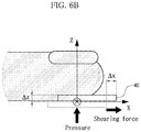
- FIG. 6B is a diagram conceptually showing an example that a tactile feel by a shearing force is transmitted in a front direction by the surface elastic member.
- FIG. 7A is a perspective view showing a user interface system of the present disclosure.
- FIG. 7B is a diagram conceptually showing an example that the system of FIG. 7A is installed to a user.
- FIGS. 8A and 8B are diagrams conceptually showing operations of the user interface system of the present disclosure, respectively.
- any component is “connected” to another component, the component may be connected directly to another component, but it should be understood that any other component can be further interposed between them.
- FIG. 1 is a perspective view showing an example of a tactile transmission device 100 of the present disclosure
- FIG. 2 is an exploded perspective view of FIG. 1
- FIG. 3A is a perspective view showing a tip-tilt elastic member 20 from the above
- FIG. 3B is a perspective view showing the tip-tilt elastic member 20 from the below
- FIG. 4A is a perspective view showing a surface elastic member 40 from the above
- FIG. 4B is a bottom view showing the surface elastic member 40 from the below.
- the tactile transmission device 100 of the present disclosure includes a base unit 10 , a tip-tilt elastic member 20 , and a cover 30 .
- the base unit 10 forms one surface of the tactile transmission device 100 .
- the tip-tilt elastic member 20 , a surface elastic member 40 and a contact portion 50 may be stacked on the base unit 10 .
- a guide pillar 13 is formed at the base unit 10 , and this will be described later.
- the tip-tilt elastic member 20 is disposed to be stacked on the base unit 10 and transmits a tactile feel to a lower portion of the finger of a user in first and second directions.
- the first direction is a direction oriented upward from a bottom surface of the finger of the user, and, for example, the first direction may be a vertical direction oriented upward from the bottom surface of the finger of the user (a Z direction indicated by an arrow in FIG. 5A ).
- the second direction is a direction intersecting the first direction at a predetermined angle, and for example, the second direction may be a direction intersecting a vertical direction and a lateral direction (a ⁇ x direction indicated by an arrow in FIG. 5B ) to the bottom surface of the finger or a front and rear direction (a ⁇ y direction indicated by an arrow in FIG. 5C ) at a predetermined angle.
- the cover 30 is disposed at an upper side of the tip-tilt elastic member 20 and forms another surface opposite to one surface of the base unit 10 .
- the tip-tilt elastic member 20 includes a load support unit 22 and a pressing unit 25 .
- the load support unit 22 is provided at a center portion of the tip-tilt elastic member 20 and supports a load of the finger of the user.
- the pressing unit 25 is provided at an edge portion of the tip-tilt elastic member 20 and is configured to be pressed in the first direction.
- a first wire-type actuator 28 is installed at the pressing unit 25 .
- the first wire-type actuator 28 presses the pressing unit 25 by elastic deformation. By doing so, the tip-tilt elastic member 20 is deformed, and the tactile feel may be transmitted to the finger of the user in the first and second directions.
- the first and second wire-type actuators 28 , 48 are solid-state actuators made of a wire, respectively.
- the solid-state actuator is an actuator that generates a mechanical energy such as force and displacement by deforming solid-state material if energy (electricity, heat, or the like) is applied from the outside.
- the solid-state material may be deformed by applying (+) and ( ⁇ ) voltages to both end portions of first wire-type actuator 28 .
- a shape memory alloy SMA
- a shape memory polymer SMA
- a dielectric elastomer may be used as the wire-type actuator according to this embodiment.
- first and second wire-type actuators 28 , 48 are wires made of SMA material and are configured to actively vary in length when energy is applied thereto.
- the first wire-type actuator 28 applies a force to the pressing unit 25 when being elastically deformed, and accordingly the tip-tilt elastic member 20 is elastically deformed to transmit the tactile feel to the finger of the user in first and second directions. This will be explained later in more detail.
- the surface elastic member 40 is elastically deformed so that the fixed portion 42 is elastically deformed in the third direction to transmit the tactile feel to the finger of the user. This will be explained later in more detail.
- the tip-tilt elastic member 20 may further include an elastic unit 27 provided between the load support unit 22 and the pressing unit 25 to be elastically deformable.
- the elastic unit 27 is elastically deformed to transmit the tactile feel to the finger of the user in first and second directions.
- the elastic unit 27 is formed to have several curves, and the elastic units 27 at four portions are symmetrical to each other based on a line extending from a portion of the load support unit 22 to a portion of the pressing unit 25 .
- the elastic unit 27 is elastically deformed so that the tactile feel is easily transmitted to the finger of the user in first and second directions.
- the load support unit 22 has a support protrusion 22 a protruding downward
- the pressing unit 25 has a pressing protrusion 25 a protruding downward.
- the lower end of the pressing protrusion 25 a is preferably formed as a curved surface.
- the base unit 10 includes a pressing accommodation portion 12 for accommodating and supporting the support protrusion 22 a and an inclined portion 15 spaced apart from the pressing protrusion 25 a by a predetermined distance, as shown in FIG. 2 .
- a pressing groove 25 b may be formed at the bottom surface of the pressing unit 25 , and the first wire-type actuator 28 may be installed at the pressing groove 25 b .
- the pressing groove 25 b is formed along an extending direction at the bottom surface of the pressing unit 25 and may extend to a side surface.
- the pressing unit 25 may be provided at four sides of the tip-tilt elastic member 20 , respectively. Referring to FIG. 3B , the pressing grooves 25 b are respectively formed at four portions of the pressing unit 25 so that the pressing unit 25 may receive a force in the upper direction by the first wire-type actuator 28 .
- first wire-type actuator 28 is installed at each of the pressing units 25 at four sides, forces may be transmitted to the pressing units 25 at four sides in the first direction. As the force is transmitted to at least one of the pressing units 25 at four sides, the force transmitted to the finger is determined as being in the first direction or the second direction.
- FIG. 5A is a diagram conceptually showing an example that a tactile feel is transmitted in a first direction by the tip-tilt elastic member 20
- FIG. 5B is a diagram conceptually showing an example that a tactile feel is transmitted in a direction intersecting the first direction to the right by the tip-tilt elastic member 20
- FIG. 5C is a diagram conceptually showing an example that a tactile feel is transmitted in a direction intersecting the first direction to the front by the tip-tilt elastic member 20 .
- the elastic units 27 adjacent to the pressing units 25 at four sides are all elastically deformed equally, and thus the finger of the user receives a force in the first direction.
- a force in the vertical direction indicated by an arrow in FIG. 5A is transmitted to the finger.
- FIG. 5B an example where the tactile feel is transmitted to the finger in a direction intersecting the first direction to the right is shown.
- the tip-tilt elastic member 20 is able to transmit a tactile feel of three degrees of freedom by applying a force to a part of the pressing units 25 at four sides.
- the tactile transmission device 100 may further include a surface elastic member 40 .
- the surface elastic member 40 is stacked on the tip-tilt elastic member 20 .
- the surface elastic member 40 transmits the tactile feel to the finger in a third direction.
- the third direction is a direction parallel to the surface in contact with the bottom of the finger, and this may be understood as a two-dimensional direction in which the tactile feel is transmitted to the finger by means of a shearing force. That is, the third direction means a direction of the force that is provided by the shearing stress when the finger touches the surface.
- the surface elastic member 40 may further include a fixed portion 42 , a movable portion 44 , and a laterally elastic portion 46 .
- the fixed portion 42 is provided at a side surface of the surface elastic member 40 and is fixed to the tip-tilt elastic member 20 .
- the movable portion 44 is movable in the third direction relative to the fixed portion 42 .
- the laterally elastic portion 46 is disposed between the fixed portion 42 and the movable portion 44 and is elastically deformed to allow the movable portion 44 to move relative to the fixed portion 42 in the third direction.
- the laterally elastic portion 46 may be provided in plural, and may be elastic bodies disposed between a point contacting the fixed portion 42 and a point contacting the movable portion 44 .
- the elastic body may be, for example, a compliant mechanism.
- the laterally elastic portion 46 may be disposed in a point-symmetric shape based on one point at the center of the movable portion 44 .
- FIGS. 4A and 4B show an example of the surface elastic member 40 .
- the fixed portions 42 having a rectangular shape are provided at upper, lower, left and right side surfaces, and the movable portion 44 has a square shape and is spaced apart from the fixed portions 42 .
- the laterally elastic portions 46 are provided at four regions between the movable portion 44 and the fixed portions 42 and are bent several times to be easily elastically deformed.
- the laterally elastic portions 46 have a point-symmetric shape based on one point at the center of the movable portion 44 .
- the surface elastic member 40 may further include a second wire-type actuator 48 .
- the second wire-type actuator 48 is installed between the fixed portion 42 and the movable portion 44 , and the second wire-type actuator 48 is elastically deformed to change a relative position of the movable portion 44 with respect to the fixed portion 42 to transmit the tactile feel to the finger in the third direction.
- each second wire-type actuator 48 is fixed to the fixed portion 42 by a bolt and caught to the movable portion 44 by a pin.
- the present disclosure is not limited to this structure.
- FIG. 4A an example where the movable portion is moved to the right is shown. Since the second wire-type actuators 48 at the upper right position and the lower right position are deformed together in FIG. 4A , the movable portion is deformed to the right.
- FIG. 6A shows an example where a shearing force acts to the right side of the finger (in the Y direction), and
- FIG. 6B shows an example where a shearing force acts to the front side of the finger (in the X direction).
- the surface elastic member 40 may transmit a tactile feel of two degrees of freedom.
- the tactile transmission device 100 of the present disclosure further includes a contact portion 50 disposed at an upper side of the surface elastic member 40 to contact the finger and transmit a tactile feel to the user.
- a pressure sensor or a force sensor capable of checking contact with the finger may be disposed at the top end of the contact portion 50 .
- a plurality of coupling holes 56 are formed in the contact portion 50
- coupling holes 47 corresponding to the coupling holes 56 of the contact portion 50 are formed in the surface elastic member 40 , so that the contact portion 50 may be coupled to the upper portion of the surface elastic member 40 .
- the contact portion 50 and the surface elastic member 40 may be coupled by bolts or pins.
- the contact portion 50 may have a finger accommodation portion 53 at an upper portion of the contact portion 50 so that the finger of the user is put therein.
- a guide pillar 13 for guiding the side surfaces of the tip-tilt elastic member 20 and the surface elastic member 40 to facilitate assembling is formed at the base unit 10 .
- FIGS. 1 and 2 show an example where the guide pillars 13 are formed to extend upward at four corners of the base unit 10 , and the corner portions of the tip-tilt elastic member 20 and the surface elastic member 40 are respectively shaped corresponding to the guide pillars 13 so as to be guided by the guide pillars 13 during assembling. After assembling, the tip-tilt elastic member 20 and the surface elastic member 40 are supported by the guide pillars 13 to easily transmit the tactile feel to the finger of the user.
- the cover 30 is coupled to an upper portion of the guide pillar 13 .
- the cover 30 may be coupled to the upper portion of the guide pillar 13 by a bolt or the like.
- a first guide groove 13 a is formed in the guide pillar 13 along a longitudinal direction of the guide pillar 13 .
- the first guide groove 13 a may accommodate the first wire-type actuator 28 .
- the cover 30 may have a fixing hole 32 formed to be fixed to the guide pillar 13 and a coupling hole 36 to which the end portion of the first wire-type actuator 28 may be fixedly coupled.
- a second guide groove 33 a is formed at the top surface of the cover 30 so that the second guide groove 33 a communicates with the first guide groove 13 a and the coupling hole 36 along the edge of the cover 30 , respectively.
- the first wire-type actuator 28 is mounted to the first guide groove 13 a , the second guide groove 33 a and the coupling hole 36 , and the end portion of the first wire-type actuator 28 may be coupled to the coupling hole 36 by a bolt.
- FIG. 7A is a perspective view showing a user interface system 200 of the present disclosure
- FIG. 7B is a diagram conceptually showing an example that the system 200 of FIG. 7A is installed to a user.
- the user interface system 200 of the present disclosure is configured to move an avatar in response to finger motion.
- the user interface system 200 of the present disclosure includes the tactile transmission device 100 of the present disclosure, a computer, and a control unit 210 .
- the tactile transmission device 100 of the present disclosure is already described in detail with reference to FIGS. 1 to 6B and thus is not described in detail here.
- the computer is connected to the tactile transmission device 100 in a wired or wireless manner and is configured to associate the avatar with the motion of the finger.
- control unit 210 enables the tactile transmission device 100 to contact the finger of the user and transmit the tactile feel thereto.
- the control unit 210 of the present disclosure may be a CPU of a wearable device such as a smart watch, and a battery of the smart watch may be used as a power source for supplying electric energy.
- FIGS. 7A and 7B show an example where the control unit 210 is implemented to be worn on the wrist, but the present disclosure is not limited thereto.
- FIGS. 8A and 8B are diagrams conceptually showing operations of the user interface system 200 of the present disclosure, respectively.
- two tactile transmission devices 100 , 100 ′ are worn on the fingers of the user, and graphics (avatars) 5 , 6 operated by the respective fingers are displayed on a monitor 3 .
- a computer (not shown) associates the graphics 5 , 6 displayed on the monitor 3 with the motion of the finger of the user.
- positions of two fingers are tracked by a finger location tracking device 7 , and if the user moves the finger, two finger graphics 5 , 6 move accordingly.
- the finger location tracking device 7 may be, for example, a sensor.
- two tactile transmission devices 100 , 100 ′ press the fingers further so that the user may feel the corresponding pressure.
- the contact portion reciprocates corresponding thereto to transmit vibration to the finger.
- the object graphic 4 of FIG. 8A may be set to have a predetermined weight.
- the user In a case where the user lifts a cup filled with water as an example with the fingers, the user feels, at the finger skin, a pressure caused by the contact with the object and a shearing force generated since the skin is pressed downward due to the weight of the cup.
- the tactile feel is transmitted in the first and second directions by the tip-tilt elastic member, and the tactile feel is transmitted in the third direction by the surface elastic member.
- the user may feel the contact to the object and the weight of the object at the same time just by moving the fingers in the air.
- the tactile transmission device of the present disclosure may achieve a high energy density by utilizing a shape memory alloy actuator, and may have a smaller and lighter design by utilizing a shape memory alloy actuator and a flexible device.
- the tactile transmission device of the present disclosure may be easily worn and taken off, have good portability, and be implemented in a serial mechanism to allow easy control. Also, only necessary tactile feels may be selectively implemented.
- the user interface system operates a virtual graphic, but the present disclosure is not limited thereto.
- the present disclosure may be used in various fields where it is necessary to transmit a sensation felt when gripping and manipulating an object in virtual reality and augmented reality, for example entertainment fields such as games and online shopping, sensory rehabilitation medical fields, and other fields such as education, travel, exhibition arts and expos.
- entertainment fields such as games and online shopping
- sensory rehabilitation medical fields and other fields such as education, travel, exhibition arts and expos.
- other fields such as education, travel, exhibition arts and expos.
- the present disclosure may be effectively used in fields where it is necessary to precisely and accurately manipulate an object in a space that is difficult to access, for example remote works using an outer space exploration robot or a deep sea exploration robot.
- the present disclosure may be used to provide a user interface in next-generation computer fields in which human and computers ses with each other.
- the device of the present disclosure may be stably worn even for fingers with different sizes to obtain a multi-degree of freedom force-feedback.
- the device of the present disclosure is capable of receiving a multi-degree of freedom force-feedback with a small and light design.
- the multi-degree of freedom force-feedback of the present disclosure exhibits high energy density characteristics.
- the present disclosure makes it possible to provide force-feedback of five degrees of freedom in total, including three degrees of freedom by the tip-tilt elastic member and two degrees of freedom by the surface elastic member.
- the tactile transmission device 100 and the user interface system 200 including the same as described above are not limited to the configuration and method of the embodiments described above, but the embodiments may be modified in various ways by combining the embodiments entirely or selectively.
Landscapes
- Engineering & Computer Science (AREA)
- General Engineering & Computer Science (AREA)
- Theoretical Computer Science (AREA)
- Human Computer Interaction (AREA)
- Physics & Mathematics (AREA)
- General Physics & Mathematics (AREA)
- User Interface Of Digital Computer (AREA)
Abstract
Description
Claims (12)
Applications Claiming Priority (2)
| Application Number | Priority Date | Filing Date | Title |
|---|---|---|---|
| KR1020170164960A KR101948079B1 (en) | 2017-12-04 | 2017-12-04 | Tactile transmission device and User interface system having the same |
| KR10-2017-0164960 | 2017-12-04 |
Publications (2)
| Publication Number | Publication Date |
|---|---|
| US20190171290A1 US20190171290A1 (en) | 2019-06-06 |
| US10990177B2 true US10990177B2 (en) | 2021-04-27 |
Family
ID=66659180
Family Applications (1)
| Application Number | Title | Priority Date | Filing Date |
|---|---|---|---|
| US16/199,708 Active 2039-02-27 US10990177B2 (en) | 2017-12-04 | 2018-11-26 | Tactile transmission device and user interface system including the same |
Country Status (2)
| Country | Link |
|---|---|
| US (1) | US10990177B2 (en) |
| KR (1) | KR101948079B1 (en) |
Families Citing this family (3)
| Publication number | Priority date | Publication date | Assignee | Title |
|---|---|---|---|---|
| KR102347030B1 (en) * | 2019-10-24 | 2022-01-03 | 한국기술교육대학교 산학협력단 | Virtual Reality Providing System |
| KR102321778B1 (en) * | 2020-02-10 | 2021-11-05 | 한국과학기술연구원 | Tele-operated Forceps-driver Variable Stiffness Master Device |
| CN115033101B (en) * | 2022-06-08 | 2024-07-05 | 苏州大学 | Finger texture tactile feedback device based on air bag driving |
Citations (5)
| Publication number | Priority date | Publication date | Assignee | Title |
|---|---|---|---|---|
| EP2375272A2 (en) | 2010-03-29 | 2011-10-12 | Seiko Instruments Inc. | Drive module and electronic device |
| JP2013537660A (en) | 2010-07-06 | 2013-10-03 | コミッサリア ア レネルジー アトミーク エ オ ゼネルジ ザルタナテイヴ | A system for simulating surface contact by tactile stimulation |
| US8830335B2 (en) | 2010-02-26 | 2014-09-09 | Cambridge Mechatronics Limited | SMA actuation apparatus |
| KR20140131175A (en) | 2013-05-03 | 2014-11-12 | 국립대학법인 울산과학기술대학교 산학협력단 | Linkage Structure of a Hand Exoskeleton for Interacting with Virtual Objects |
| KR101658513B1 (en) | 2015-04-23 | 2016-09-21 | 한국과학기술연구원 | Tactile transmission device and User interface system having the same |
-
2017
- 2017-12-04 KR KR1020170164960A patent/KR101948079B1/en not_active Expired - Fee Related
-
2018
- 2018-11-26 US US16/199,708 patent/US10990177B2/en active Active
Patent Citations (8)
| Publication number | Priority date | Publication date | Assignee | Title |
|---|---|---|---|---|
| US8830335B2 (en) | 2010-02-26 | 2014-09-09 | Cambridge Mechatronics Limited | SMA actuation apparatus |
| EP2375272A2 (en) | 2010-03-29 | 2011-10-12 | Seiko Instruments Inc. | Drive module and electronic device |
| JP2011209467A (en) | 2010-03-29 | 2011-10-20 | Seiko Instruments Inc | Drive module and electronic device |
| JP2013537660A (en) | 2010-07-06 | 2013-10-03 | コミッサリア ア レネルジー アトミーク エ オ ゼネルジ ザルタナテイヴ | A system for simulating surface contact by tactile stimulation |
| KR20140131175A (en) | 2013-05-03 | 2014-11-12 | 국립대학법인 울산과학기술대학교 산학협력단 | Linkage Structure of a Hand Exoskeleton for Interacting with Virtual Objects |
| KR101658513B1 (en) | 2015-04-23 | 2016-09-21 | 한국과학기술연구원 | Tactile transmission device and User interface system having the same |
| WO2016171335A1 (en) * | 2015-04-23 | 2016-10-27 | 한국과학기술연구원 | Tactile transmission device and user interface system having same |
| US20180136729A1 (en) * | 2015-04-23 | 2018-05-17 | Korea Institute Of Science And Technology | Tactile transmission device and user interface system having same |
Non-Patent Citations (3)
| Title |
|---|
| Domencio Prattichizzo et al., "Towards Wearability in Fingertip Haptics: A 3-DoF Wearable Device for Cutaneous Force Feedback", IEEE Transactions on Haptics, 2013, pp. 506-516, vol. 6, No. 4. |
| Gabriele Frediani et al., "Wearable wireless tactile display for virtual interactions with soft bodies", Frontiers in Bioengineering and Biotechnology, 2014, vol. 2, Article 31. |
| Robert Scheibe et al., "Tactile Feedback at the Finger Tips for Improved Direct Interaction in Immersive Environments", IEEE Symposium on 3D User Interfaces 2007, pp. 123-130. |
Also Published As
| Publication number | Publication date |
|---|---|
| KR101948079B1 (en) | 2019-05-20 |
| US20190171290A1 (en) | 2019-06-06 |
Similar Documents
| Publication | Publication Date | Title |
|---|---|---|
| US10248208B2 (en) | Tactile transmission device and user interface system having same | |
| JP6039562B2 (en) | Three-dimensional tactile transmission device, method and system | |
| JP7265567B2 (en) | Finger-worn device using sensor and tactile sense | |
| US9054605B2 (en) | Haptic module using piezoelectric element | |
| US9189065B2 (en) | Side-type force sense interface | |
| US10293249B2 (en) | Haptic peripheral having a deformable substrate configured for amplified deformation | |
| US10990177B2 (en) | Tactile transmission device and user interface system including the same | |
| KR102225783B1 (en) | Haptic controller, and System and Method for providing haptic feedback using the haptic controller | |
| US8138895B2 (en) | Force/tactile feedback device | |
| KR100958908B1 (en) | Tactile presentation device and tactile presentation method using the same | |
| US10671169B2 (en) | Tactile feedback generating apparatus and system for virtual object manipulation | |
| US7339574B2 (en) | Haptic mouse interface system for providing force and tactile feedbacks to user's fingers and arm | |
| KR20190013540A (en) | Single actuator haptic effects | |
| US9030306B2 (en) | Apparatus and method for 3 degree of freedom (3DOF) tactile feedback | |
| CN102750017B (en) | Operation equipment | |
| US20160054800A1 (en) | Integrated haptic feedback simulating device using kinesthesia providing module including magnetorheological fluid and thin-film-type tactile sensation providing module | |
| CN102339163A (en) | Contact-pressure detecting apparatus and input apparatus | |
| US20050110758A1 (en) | Tactile mouse interface system | |
| GB2583294A (en) | Shape memory alloy actuator | |
| Thai et al. | Soft wearable haptic display and flexible 3d force sensor for teleoperated surgical systems | |
| Zubrycki et al. | Novel haptic glove-based interface using jamming principle | |
| JP6852677B2 (en) | Parallel link robot and operating device | |
| Nozaki et al. | Real-world haptics for motion realization | |
| KR101643576B1 (en) | A thimble type force feedback device | |
| KR20140083895A (en) | Method for obtaining 3dimension haptic and display apparatus using thereof |
Legal Events
| Date | Code | Title | Description |
|---|---|---|---|
| AS | Assignment |
Owner name: KOREA INSTITUTE OF SCIENCE AND TECHNOLOGY, KOREA, Free format text: ASSIGNMENT OF ASSIGNORS INTEREST;ASSIGNORS:HWANG, DONGHYUN;KIM, KEEHOON;LIM, BYEONGKYU;AND OTHERS;SIGNING DATES FROM 20181107 TO 20181108;REEL/FRAME:047581/0017 Owner name: CENTER OF HUMAN-CENTERED INTERACTION FOR COEXISTEN Free format text: ASSIGNMENT OF ASSIGNORS INTEREST;ASSIGNORS:HWANG, DONGHYUN;KIM, KEEHOON;LIM, BYEONGKYU;AND OTHERS;SIGNING DATES FROM 20181107 TO 20181108;REEL/FRAME:047581/0017 Owner name: CENTER OF HUMAN-CENTERED INTERACTION FOR COEXISTENCE, KOREA, REPUBLIC OF Free format text: ASSIGNMENT OF ASSIGNORS INTEREST;ASSIGNORS:HWANG, DONGHYUN;KIM, KEEHOON;LIM, BYEONGKYU;AND OTHERS;SIGNING DATES FROM 20181107 TO 20181108;REEL/FRAME:047581/0017 Owner name: KOREA INSTITUTE OF SCIENCE AND TECHNOLOGY, KOREA, REPUBLIC OF Free format text: ASSIGNMENT OF ASSIGNORS INTEREST;ASSIGNORS:HWANG, DONGHYUN;KIM, KEEHOON;LIM, BYEONGKYU;AND OTHERS;SIGNING DATES FROM 20181107 TO 20181108;REEL/FRAME:047581/0017 |
|
| FEPP | Fee payment procedure |
Free format text: ENTITY STATUS SET TO UNDISCOUNTED (ORIGINAL EVENT CODE: BIG.); ENTITY STATUS OF PATENT OWNER: SMALL ENTITY |
|
| FEPP | Fee payment procedure |
Free format text: ENTITY STATUS SET TO SMALL (ORIGINAL EVENT CODE: SMAL); ENTITY STATUS OF PATENT OWNER: SMALL ENTITY |
|
| STPP | Information on status: patent application and granting procedure in general |
Free format text: DOCKETED NEW CASE - READY FOR EXAMINATION |
|
| STPP | Information on status: patent application and granting procedure in general |
Free format text: NON FINAL ACTION MAILED |
|
| STPP | Information on status: patent application and granting procedure in general |
Free format text: ADVISORY ACTION MAILED |
|
| STPP | Information on status: patent application and granting procedure in general |
Free format text: NOTICE OF ALLOWANCE MAILED -- APPLICATION RECEIVED IN OFFICE OF PUBLICATIONS |
|
| STPP | Information on status: patent application and granting procedure in general |
Free format text: PUBLICATIONS -- ISSUE FEE PAYMENT RECEIVED |
|
| STPP | Information on status: patent application and granting procedure in general |
Free format text: PUBLICATIONS -- ISSUE FEE PAYMENT VERIFIED |
|
| STCF | Information on status: patent grant |
Free format text: PATENTED CASE |
|
| AS | Assignment |
Owner name: KOREA INSTITUTE OF SCIENCE AND TECHNOLOGY, KOREA, REPUBLIC OF Free format text: ASSIGNMENT OF ASSIGNORS INTEREST;ASSIGNORS:KOREA INSTITUTE OF SCIENCE AND TECHNOLOGY;CENTER OF HUMAN-CENTERED INTERACTION FOR COEXISTENCE INTERNATIONAL COOPERATION;REEL/FRAME:057941/0366 Effective date: 20210924 |
|
| AS | Assignment |
Owner name: KOREA INSTITUTE OF SCIENCE AND TECHNOLOGY, KOREA, REPUBLIC OF Free format text: CORRECTIVE ASSIGNMENT TO CORRECT THE REMOVE APPLICATION NO. 14293189 PATENT NUMBER 8938131 PREVIOSLY RECORDED PREVIOUSLY RECORDED AT REEL: 057941 FRAME: 0366. ASSIGNOR(S) HEREBY CONFIRMS THE ASSIGNMENT;ASSIGNORS:KOREA INSTITUTE OF SCIENCE AND TECHNOLOGY;CENTER OF HUMAN-CENTERED INTERACTION FOR COEXISTENCE INTERNATIONAL COOPERATIO;REEL/FRAME:059369/0179 Effective date: 20210924 Owner name: KOREA INSTITUTE OF SCIENCE AND TECHNOLOGY, KOREA, REPUBLIC OF Free format text: CORRECTIVE ASSIGNMENT TO CORRECT THE REMOVE APPLICATION NO. 14293189 PATENT NUMBER 893131 PREVIOSLY RECORDED PREVIOUSLY RECORDED AT REEL: 057941 FRAME: 0366. ASSIGNOR(S) HEREBY CONFIRMS THE ASSIGNMENT;ASSIGNORS:KOREA INSTITUTE OF SCIENCE AND TECHNOLOGY;CENTER OF HUMAN-CENTERED INTERACTION FOR COEXISTENCE INTERNATIONAL COOPERATIO;REEL/FRAME:059369/0179 Effective date: 20210924 |
|
| MAFP | Maintenance fee payment |
Free format text: PAYMENT OF MAINTENANCE FEE, 4TH YR, SMALL ENTITY (ORIGINAL EVENT CODE: M2551); ENTITY STATUS OF PATENT OWNER: SMALL ENTITY Year of fee payment: 4 |