US10983348B2 - Head mount wearable device - Google Patents
Head mount wearable device Download PDFInfo
- Publication number
- US10983348B2 US10983348B2 US16/038,804 US201816038804A US10983348B2 US 10983348 B2 US10983348 B2 US 10983348B2 US 201816038804 A US201816038804 A US 201816038804A US 10983348 B2 US10983348 B2 US 10983348B2
- Authority
- US
- United States
- Prior art keywords
- head mount
- mobile device
- wearable device
- locking portion
- button
- Prior art date
- Legal status (The legal status is an assumption and is not a legal conclusion. Google has not performed a legal analysis and makes no representation as to the accuracy of the status listed.)
- Expired - Fee Related, expires
Links
Images


Classifications
-
- G—PHYSICS
- G02—OPTICS
- G02B—OPTICAL ELEMENTS, SYSTEMS OR APPARATUS
- G02B27/00—Optical systems or apparatus not provided for by any of the groups G02B1/00 - G02B26/00, G02B30/00
- G02B27/01—Head-up displays
- G02B27/017—Head mounted
- G02B27/0172—Head mounted characterised by optical features
-
- G—PHYSICS
- G02—OPTICS
- G02B—OPTICAL ELEMENTS, SYSTEMS OR APPARATUS
- G02B27/00—Optical systems or apparatus not provided for by any of the groups G02B1/00 - G02B26/00, G02B30/00
- G02B27/01—Head-up displays
- G02B27/017—Head mounted
-
- G—PHYSICS
- G02—OPTICS
- G02B—OPTICAL ELEMENTS, SYSTEMS OR APPARATUS
- G02B27/00—Optical systems or apparatus not provided for by any of the groups G02B1/00 - G02B26/00, G02B30/00
- G02B27/01—Head-up displays
- G02B27/017—Head mounted
- G02B27/0176—Head mounted characterised by mechanical features
-
- G—PHYSICS
- G02—OPTICS
- G02B—OPTICAL ELEMENTS, SYSTEMS OR APPARATUS
- G02B27/00—Optical systems or apparatus not provided for by any of the groups G02B1/00 - G02B26/00, G02B30/00
- G02B27/01—Head-up displays
- G02B27/0149—Head-up displays characterised by mechanical features
-
- G—PHYSICS
- G02—OPTICS
- G02B—OPTICAL ELEMENTS, SYSTEMS OR APPARATUS
- G02B27/00—Optical systems or apparatus not provided for by any of the groups G02B1/00 - G02B26/00, G02B30/00
- G02B27/09—Beam shaping, e.g. changing the cross-sectional area, not otherwise provided for
- G02B27/0938—Using specific optical elements
- G02B27/095—Refractive optical elements
- G02B27/0955—Lenses
-
- G—PHYSICS
- G02—OPTICS
- G02B—OPTICAL ELEMENTS, SYSTEMS OR APPARATUS
- G02B27/00—Optical systems or apparatus not provided for by any of the groups G02B1/00 - G02B26/00, G02B30/00
- G02B27/01—Head-up displays
- G02B27/0101—Head-up displays characterised by optical features
- G02B2027/0132—Head-up displays characterised by optical features comprising binocular systems
-
- G—PHYSICS
- G02—OPTICS
- G02B—OPTICAL ELEMENTS, SYSTEMS OR APPARATUS
- G02B27/00—Optical systems or apparatus not provided for by any of the groups G02B1/00 - G02B26/00, G02B30/00
- G02B27/01—Head-up displays
- G02B27/0101—Head-up displays characterised by optical features
- G02B2027/014—Head-up displays characterised by optical features comprising information/image processing systems
-
- G—PHYSICS
- G02—OPTICS
- G02B—OPTICAL ELEMENTS, SYSTEMS OR APPARATUS
- G02B27/00—Optical systems or apparatus not provided for by any of the groups G02B1/00 - G02B26/00, G02B30/00
- G02B27/01—Head-up displays
- G02B27/0149—Head-up displays characterised by mechanical features
- G02B2027/0154—Head-up displays characterised by mechanical features with movable elements
Definitions
- the disclosure relates to a head mount wearable device. More particularly, the disclosure relates to a head mount wearable device to which a mobile device is detachably attached.
- wearable devices include a head mount wearable device that is worn on the head of a user, smart glasses, a smart watch or a wristband, a contact lens type device, a ring type device, a shoe type device, a clothing type device or a glove type device, and may have various shapes that can be detachably attached to the body or the clothing of users. Since wearable devices are worn directly on a body, portability and accessibility of a user can be improved.
- a head mount wearable device of wearable devices can be provided as a part of a mobile device (e.g., a smartphone) or may be separably combined with a mobile device.
- a head mount wearable device can provide images using the display of a mobile device.
- the holder assembly may be made of an elastic material to be able to cover the mobile device.
- the elastic holder assembly may be broken due to repeated combination with a mobile device.
- a holder assembly of a head mount wearable device may be configured to fix only mobile devices having a specific size, so it may be difficult to mount mobile devices smaller than the specific size.
- a head mount wearable device on which mobile devices having various sizes can be provided.
- a head mount wearable device includes a housing having a first surface and a second surface, in which the first surface faces the face of a user and the second surface is opposite to the first surface when a user wears the head mount wearable device, a pair of lenses disposed inside at least one opening formed through the housing from the first surface to the second surface, at least one mounting member connected to the housing and configured to be worn by a user such that the pair of lenses are positioned in front of the eyes of a user, and a holder assembly formed on the second surface or close to the second surface to hold a mobile device including a display and holding the mobile device 10 such that the display of the mobile device faces the opening.
- the holder assembly is positioned not to close the opening and may include a mechanical button disposed on the second surface to be pressed down when the mobile device is held by the holder assembly, a first member sliding on the second surface in a first direction from a first position to a second position in which the first position is closer to the opening than the second position when seen from above the second surface a second member connected to the first member, being able to rotate about a shaft extending in a second direction perpendicular to the first direction, and forming a recess in cooperation with the first member to receive a portion of the mobile device, and a first biasing member moving the first member in the first direction when the button is pressed down, and configured such that the second member is close to the second surface.
- a head mount wearable device in accordance with another aspect of the disclosure, includes a housing having a space in which at least one lens is disposed and a mobile device is mounted, a connector assembly rotatably connected to the housing and electrically connected to the mobile device, and a holder assembly included in the housing and configured to slide when a button on the housing is pressed down, to cover a portion of the mobile device, in which the holder assembly may include a body combined with the housing, a first member configured to slide on the body, a first biasing member disposed between the body and the first member and providing elasticity to the first member, a second member rotatably connected to the first member to cover a portion of the mobile device, locking members configured to lock or unlock the second member to or from the body, a button configured to unlock the locking members by being pressed and rotated by the mobile device, and a second biasing member configured to prevent the button from protruding out of the housing.
- a holder assembly of a head mount wearable device includes a mechanical button, a first member configured to slide on a surface of the head mount wearable device in a first direction from a first position to a second position, in which the first position is closer to the opening than the second position when seen from above the first surface, a second member connected to the first member, being rotatable about a shaft extending in a second direction perpendicular to the first direction, and forming a recess in cooperation with the first member to receive a portion of the mobile device, and a first biasing member configured to move the first member in the first direction when the button is pressed down, and configured such that the second member is close to the second surface.
- a head mount wearable device in accordance with another aspect of the disclosure, includes a housing having a space in which at least one lens is disposed and a mobile device is mounted, a connector assembly rotatably connected to the housing and electrically connected to the mobile device, and a holder assembly configured to slide when a button on the housing is pressed down, to cover a portion of the mobile device.
- the wearable device can be detachably coupled to mobile devices having various sizes.
- FIG. 1 is a front view illustrating a head mount wearable device according to various embodiments of the disclosure
- FIG. 2 is an exploded perspective view illustrating a holder assembly of a head mount wearable device according to various embodiments of the disclosure
- FIG. 3 is a perspective view before a holder assembly and a housing are combined in a head mount wearable device according to various embodiments of the disclosure
- FIG. 4 is a side view illustrating a rotation a lever of a holder assembly of a head mount wearable device according to various embodiments of the disclosure
- FIG. 5 is a side view illustrating a rotation a second member of a holder assembly of a head mount wearable device according to various embodiments of the disclosure
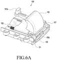
- FIG. 6A is a perspective view before a holder assembly slides a head mount wearable device according to various embodiments of the disclosure
- FIG. 6B is a front view before a holder assembly slides in a head mount wearable device according to various embodiments of the disclosure
- FIG. 6C is a cross-sectional view taken along line A-A′ of FIG. 6B according to various embodiments of the disclosure.
- FIG. 6D is a cross-sectional view taken along line B-B′ of FIG. 6B according to various embodiments of the disclosure.
- FIG. 7A is a perspective view after a holder assembly slides a head mount wearable device according to various embodiments of the disclosure.
- FIG. 7B is a front view after a holder assembly slides in a head mount wearable device according to various embodiments of the disclosure.
- FIG. 7C is a cross-sectional view taken along line C-C′ of FIG. 7B according to various embodiments of the disclosure.
- FIG. 7D is a cross-sectional view taken along line D-D′ of FIG. 7B according to various embodiments of the disclosure.
- FIG. 8 is a schematic view before a mobile device is mounted on a head mount wearable device according to various embodiments of the disclosure.
- FIG. 9 is a schematic view when a connector of a mobile device is coupled to a connector assembly of a head mount wearable device according to various embodiments of the disclosure.
- FIG. 10 is a cross-sectional view when a mobile device is disposed in a space of a head mount wearable device according to various embodiments of the disclosure.
- FIG. 11 is a cross-sectional view when a portion of a mobile device is covered by a holder assembly of a head mount wearable device according to various embodiments of the disclosure.
- FIG. 12 is a flowchart illustrating a method of operating a head mount wearable device according to various embodiments of the disclosure.
- module may include a unit consisting of hardware, software, or firmware, and may, for example, be used interchangeably with the term “logic”, “logical block”, “component”, “circuit”, or the like.
- the “module” may be an integrated component, or a minimum unit for performing one or more functions or a part thereof.
- the module may be implemented by an application-specific integrated circuit (ASIC).
- ASIC application-specific integrated circuit
- Various embodiments as described herein may be implemented by software (e.g., program) including an instruction stored in machine-readable storage media (e.g., internal memory or external memory).
- the machine is a device that calls the stored instruction from the storage media and can operate according to the called instruction, and may include an electronic device (e.g., electronic device) according to the disclosed embodiments.
- the instruction when executed by a processor (e.g., processor), may cause the processor to directly execute a function corresponding to the instruction or cause other elements to execute the function under the control of the processor.
- the instruction may include a code that is generated or executed by a compiler or interpreter.
- the machine-readable storage media may be provided in the form of non-transitory storage media.
- the term “non-transitory” only means that the storage media is tangible without including a signal, irrespective of whether data is semi-permanently or transitorily stored in the storage media.
- a method according to various embodiments disclosed herein may be included in a computer program product.
- the computer program product may be traded between a seller and a purchaser as an item.
- the computer program product may be distributed in the type of a device-readable storage medium (e.g., a compact disc read only memory (CD-ROM) or through an application store (e.g., Play StoreTM) on the web.
- a device-readable storage medium e.g., a compact disc read only memory (CD-ROM) or through an application store (e.g., Play StoreTM) on the web.
- an application store e.g., Play StoreTM
- the computer program product is distributed on the web, at least a portion of the computer program product may be at least temporarily stored or created in a storage medium, such as the memory of the server of the manufacturer, the server of an application store, or a relay server.
- Non-transitory computer readable recording medium is any data storage device that can store data which can be thereafter read by a computer system.
- Examples of the non-transitory computer readable recording medium include a Read-Only Memory (ROM), a Random-Access Memory (RAM), Compact Disc-ROMs (CD-ROMs), magnetic tapes, floppy disks, and optical data storage devices.
- the non-transitory computer readable recording medium can also be distributed over network coupled computer systems so that the computer readable code is stored and executed in a distributed fashion.
- functional programs, code, and code segments for accomplishing the disclosure can be easily construed by programmers skilled in the art to which the disclosure pertains.
- the various embodiments of the disclosure as described above typically involve the processing of input data and the generation of output data to some extent.
- This input data processing and output data generation may be implemented in hardware or software in combination with hardware.
- specific electronic components may be employed in a mobile device or similar or related circuitry for implementing the functions associated with the various embodiments of the disclosure as described above.
- one or more processors operating in accordance with stored instructions may implement the functions associated with the various embodiments of the disclosure as described above. If such is the case, it is within the scope of the disclosure that such instructions may be stored on one or more non-transitory processor readable mediums.
- processor readable mediums examples include a ROM, a RAM, CD-ROMs, magnetic tapes, floppy disks, and optical data storage devices.
- the processor readable mediums can also be distributed over network coupled computer systems so that the instructions are stored and executed in a distributed fashion.
- functional computer programs, instructions, and instruction segments for accomplishing the disclosure can be easily construed by programmers skilled in the art to which the present pertains.
- Components may be single units or may include various elements, and some of corresponding sub-components may be omitted or other sub-components may be further included in various embodiments.
- some components e.g., a module or a program
- FIG. 1 is a front view illustrating a head mount wearable device according to various embodiments of the disclosure.
- a head mount wearable device 100 may include a housing 101 , a mounting member 119 , a connector assembly 107 , and a holder assembly 105 .
- the housing 101 can be worn on a portion of the head of a user.
- the housing 101 may be made of resin.
- the housing 101 is not limited to resin and may be made of various materials that are rigid and light for comfortable fit for users.
- the housing 101 may have a first surface, a second surface, and at least one opening 113 .
- the first surface may face the user's face when the wearable device 100 is mounted on the user.
- the first surface may be curved to correspond to the user's face.
- the first surface may have a face seat (not shown) that is brought in contact with a portion of the user's face.
- the face seat may be made of an elastic material.
- the face seat may be formed like a cushion, such as a sponge.
- the face seat is formed like a cushion, so it can provide a comfortable fit when it is brought in contact with the user's face.
- the second surface may be opposite to the first surface.
- the opening 113 may be formed through the housing from the first surface to the second surface.
- a pair of lenses 102 may be disposed inside the opening 113 . The positions of the pair of lenses 102 may correspond to the positions of the eyes of a user when the user wears the wearable device.
- a third opening 113 exposing a portion of a button 157 may be formed inside the space 115 .
- the space 115 receiving a mobile device e.g., the mobile device 10 of FIG. 10 to be described below
- the space 115 receiving a mobile device may be formed by the second surface of the housing 101 .
- Retainers 116 that are brought in contact with the sides of the mobile device 10 may be formed on the sides of the space 115 .
- the retainers 116 each may include a first retainer 116 a , a second retainer 116 b , and a third retainer 116 c .
- the first, second, and third retainers 116 a , 116 b , and 116 c may be configured to be protruded or received from or in the housing 101 .
- the first retainers 116 a may protrude from the side of the space 115 further than the second retainers 116 b .
- the second retainers 116 b may protrude from the side of the space 115 further than the third retainers 116 c .
- the first retainers 116 a can hold and support the sides of the mobile device 10 .
- the second retainers 116 b can hold and support the sides of the mobile device 10 .
- the second retainers 116 b may be pressed by the mobile device 10 having the second size and received in the housing 101 .
- the third retainers 116 c can hold and support the sides of the mobile device 10 .
- the second retainers 116 b and the third retainers 116 c may be pressed by the mobile device 10 and received in the housing 101 .
- the retainers 116 a , 116 b , and 116 c can prevent shaking of mobile devices 10 having various sizes (a first size, a second size, and a third size) from shaking by holding the sides of the mobile devices 10 .
- the retainers 116 a , 116 b , and 116 c can a shock from being applied to the mobile devices 10 or the housing 101 when the mobile devices 10 are fit into the space 115 of the mobile device 10 by holding portions of the sides of the mobile devices 10 .
- the retainers 116 can align the mobile devices 10 in the space 115 or prevent the mobile devices 10 from being inclined in the space 115 by holding portions of the sides of the mobile devices 10 .
- display protectors 117 may be disposed on the inner side of the space 115 .
- the display protectors 117 may protrude from the inner side.
- the display protectors 117 may be made of an elastic material.
- the display protectors 117 can come in contact with the display of the mobile device 10 . Since the display protectors 117 come in contact with the display of the mobile device 10 , the entire display of the mobile device 10 can be prevented from coming in contact with the entire inner side of the space 115 .
- the mounting member 119 is connected to the housing 101 for a user to be able to wear the housing 101 .
- the mounting member 119 may be formed in a band type that covers the head of a user.
- the mounting member 119 may include a band part (not shown) and a stretcher (not shown).
- the stretcher allows for adjusting the length of the band to fit the heads of various users.
- the band part may be formed in various types, such as a strap, temples, a helmet, or the like.
- the connector assembly 107 may be disposed on the second surface of the housing 101 or may be positioned close to the second surface.
- the connector assembly 107 may be rotatably coupled to the housing 101 .
- the connector assembly 107 can be connected to the connector of the mobile device 10 (e.g., the connector 11 of the mobile device of FIG. 10 ) when the mobile device 10 is mounted on the wearable device 100 .
- the wearable device 100 can provide an electrical signal to the mobile device 10 through the connector assembly 107 and the connector 11 of the mobile device.
- the opening 113 may be positioned between the holder assembly 105 and the connector assembly 107 .
- the holder assembly 105 may be positioned in a predetermined area at the left side of the opening 113 on the housing 101 and the connector assembly 107 may be positioned in another predetermined area at the right side of the opening 113 on the housing 101 .
- the holder assembly 105 may be disposed on the second surface of the housing 101 or on a side of the housing 101 close to the second surface.
- the holder assembly 105 may hold a portion of the mobile device 10 to keep the mobile device 10 in the space.
- the holder assembly 105 can hold a portion of the mobile device 10 and the connector assembly 107 can hold another portion of the mobile device 10 .
- the holder assembly 105 will be described below with reference to the drawings.
- FIG. 2 is an exploded perspective view illustrating a holder assembly of a head mount wearable device according to various embodiments of the disclosure.
- the holder assembly 105 may include a body 151 , a first member 153 , a second member 155 , and a first biasing member 152 or a second biasing member 158 .
- the body 151 may be disposed in the housing (e.g., the housing 101 of FIG. 1 ).
- the body 151 may have flanges 151 a each having first fastening holes 151 b and second fastening holes (not shown) corresponding to the first fastening holes 151 a may be formed in the housing 101 .
- Bolts (not shown) are inserted in the first fastening holes 151 b and the second fastening holes, so the body 151 can be combined with the housing 101 .
- the first member 153 can slide on the body 151 .
- first guides 153 c may be formed on the bottom of the first member 153 and second guides 151 c corresponding to the first guides 153 c may be formed on the top of the body 151 .
- the first guides 153 c of the first member 153 can slide along the second guides 151 c of the body 151 .
- the second member 155 may be rotatably coupled to the first member 153 .
- Rotational portions 153 a may be formed at the first member 153 .
- the rotational portions 153 a are formed like holes.
- the rotational portions 153 a are not limited to the holes and may be formed like grooves.
- the second member 155 may have a shaft 155 a inserted in the rotational portions 153 a .
- the shaft 155 a may extend and protrude from sides of the second member 155 . Since the shaft 155 a is inserted in the rotational portions 153 a , the second member 155 can be rotatably coupled to the first member 153 .
- the first member 153 may form a recess 155 c for receiving a portion of a mobile device in cooperation with the second member 155 .
- the first biasing member 152 can connect the body 151 and the first member 153 to each other.
- the first biasing member 152 may have elasticity.
- the first biasing member 152 may be a spring.
- the first biasing member 152 may be coupled to the body 151 at an end and to the first member 153 at the other end.
- the first biasing member 152 can provide elasticity to the first member 153 and can slide the first member 153 on the body 151 .
- the second biasing member 158 may be disposed between the button 157 and the inner side of the housing (e.g., the housing 101 of FIG. 1 ).
- the second biasing member 158 can press the button 157 .
- FIG. 3 is a perspective view before a holder assembly of a head mount wearable device according to various embodiments of the disclosure.
- the housing 101 may have a second opening 113 b formed close to the opening 113 .
- the second member 155 can be exposed outside the housing 101 through the second opening 113 b.
- the button 157 may be arranged in parallel with the body 151 .
- a protrusion 157 a of the button 157 can be exposed outside the housing 101 through a third opening (e.g., the third opening 113 d of FIG. 1 ) formed through the second surface of the housing 101 .
- FIG. 4 is a side view illustrating a rotation of a button of holder assembly in a head mount wearable device according to various embodiments of the disclosure.
- the button 157 may have a lever 157 c , a protrusion 157 a , and a second shaft 157 b .
- the lever 157 c may have a longitudinal direction and may be arranged in parallel with the body 151 .
- the protrusion 157 a may perpendicularly extend from an end of the lever 157 c .
- the second shaft 157 b may extend from the lever 157 c and may be rotatably coupled to the body 151 .
- the lever 157 c when the protrusion 157 a is pressed down by an external force, the lever 157 c can be rotated about the second shaft 157 b .
- the other end of the lever 157 c can moved in the opposite direction to the protrusion 157 a pressed down.
- FIG. 5 is a side view illustrating a rotation of a second member of a holder assembly in a head mount wearable device according to various embodiments of the disclosure.
- the second member 155 may have a shaft 155 a .
- the shaft 155 a may be inserted in the rotational portions (e.g., the rotational portions 153 a of FIG. 2 ) of the first member 153 .
- the second member 155 can be rotated about the shaft 155 a .
- the second member 155 can be rotated away from the second surface of the housing 101 .
- the second member 155 is rotated toward the second surface of the housing 101 , when a mobile device (e.g., the mobile device 10 ) of FIG. 10 is mounted into the space, the second member 155 can cover a portion of the mobile device 10 .
- FIG. 6A is a perspective view before a holder assembly of a head mount wearable device according to various embodiments slides.
- FIG. 6B is a front view before a holder assembly slides a head mount wearable device according to various embodiments.
- FIG. 6C is a cross-sectional view taken along line A-A′ of FIG. 6B according to various embodiments.
- FIG. 6D is a cross-sectional view taken along line B-B′ of FIG. 6B according to various embodiments.
- the holder assembly 105 may include locking members 151 c and 155 c that lock or unlock the second member 153 to or from the body 151 .
- the locking members 151 c and 155 c may have a first locking portion 151 c and a second locking portion 155 c .
- the first locking portion 151 c is formed at the body 151 and may have a groove shape.
- the second locking portion 155 c is formed at the second member 155 and can be locked or unlocked to or from the first locking portion 151 c .
- the second locking portion 1 155 c may have a protrusion shape corresponding to the groove shape of the first locking portion 151 c .
- the second locking member 155 can be locked to the first locking portion 151 c by rotating about the first member 153 .
- the first member 153 connected to the second member 155 can be prevented from sliding due to the elasticity of the first biasing member 152 .
- the other end of 157 c of the button 157 may come in contact with the second locking portion 155 c .
- the second locking portion 155 c can press the other end 157 c of the button by being locked to the first locking portion 151 c .
- the button 155 can be rotated about the second shaft (the second shaft 157 b of FIG. 4 ).
- the protrusion 157 a of the button can be moved in the opposite direction to the pressing direction of the other end 157 c of the button 157 .
- the protrusion 157 a of the button may protrude into the space (e.g., the space 115 of FIG. 1 ) of the housing 101 .
- FIG. 7A is a perspective view after a holder assembly of a head mount wearable device according to various embodiments slides.
- FIG. 7B is a front view after a holder assembly slides in a head mount wearable device according to various embodiments.
- FIG. 7C is a cross-sectional view taken along line C-C′ of FIG. 7B according to various embodiments.
- FIG. 7D is a cross-sectional view taken along line D-D′ of FIG. 7B according to various embodiments.
- the button 157 when the protrusion 157 c of the button 157 is pressed down, the button 157 can be rotated about the second shaft (e.g., the second shaft 157 b of FIG. 4 ). As the button 157 is rotated, the other end 157 c of the button 157 can lift the second locking portion 155 c . For example, the second locking portion 155 c can be moved in the opposite direction to the button 157 pressed down. As the second locking portion 155 c is moved, it can be unlocked from the first locking portion 1 151 c . As the second locking portion 155 c and the first locking portion 151 c are unlocked from each other, the first member 153 can be moved in the first direction ⁇ circle around (1) ⁇ by the elasticity of the first biasing member 152 .
- FIG. 8 is a schematic view before a mobile device is mounted on a head mount wearable device according to various embodiments of the disclosure.
- FIG. 9 is a schematic view when a connector assembly of a head mount wearable device according to various embodiments.
- the connector assembly 107 may include an electrical connector 171 that is connected to the connector 11 of the mobile device 10 .
- the connector assembly 107 can be rotated on the housing 101 such that the electrical connector 171 is inclined with respect to the housing 101 .
- the mobile device 10 can be inserted toward the connector assembly 107 at an angle with respect to the housing 101 .
- the other portion of the mobile device 10 may be covered by the connector assembly 107 .
- the electrical connector 171 can be electrically connected to the connector 11 of the mobile device 10 by being inserted therein.
- FIG. 10 is a schematic view when a mobile device is mounted in a space of a head mount wearable device according to various embodiments of the disclosure.
- the mobile device 10 can be connected to the connector assembly 107 and rotated with the connector assembly 107 .
- the mobile device 10 can be received into the space 115 by rotating.
- the display 12 of the mobile device 10 may be positioned to fact a pair of lenses (e.g., the pair of lenses 102 of FIG. 1 ).
- the mobile device 10 can press down the button 157 when being received into the space 115 .
- FIG. 11 is a cross-sectional view when a holder assembly of a head mount wearable device according to various embodiments.
- the holder assembly 105 can be moved in the first direction ⁇ circle around (1) ⁇ . As the holder assembly 105 is moved in the first direction ⁇ circle around (1) ⁇ , the holder assembly 105 can cover a portion of the mobile device 10 .
- the mobile device 10 can be kept on the wearable device 100 by being partially covered by the connector assembly 107 and the holder assembly 105 .
- FIG. 12 is a flowchart illustrating a method of operating a head mount wearable device according to various embodiments of the disclosure.
- the connector assembly (e.g., the connector assembly 107 of FIG. 9 ) can be connected to the connector (e.g., the connector 11 of FIG. 9 ) of the mobile device (e.g., the mobile device 10 of FIG. 9 ) by being rotated ( 201 ).
- the mobile device 10 in operation 203 , when the mobile device 10 is mounted into the space (e.g., the space 115 of FIG. 1 ) of the housing 101 , the mobile device 10 can press down the button 157 ( 203 ).
- the locking members e.g., the locking members 151 c and 155 c of FIG. 7
- the holder assembly e.g., the holder assembly 105 of FIG. 7A
- the holder assembly 105 in operation 207 , can be slid in the first direction ⁇ circle around (1) ⁇ by the elasticity of the first biasing member (e.g., the first biasing member 282 of FIG. 6 ) of the holder assembly 105 ( 207 ).
- the first biasing member e.g., the first biasing member 282 of FIG. 6
- the holder assembly 105 in operation 209 , can cover a portion of the mobile device 10 ( 209 ).
- the button 157 in operation 211 , can be prevented from protruding into the space 115 of the housing 101 by the elasticity of the second biasing member (e.g., the second biasing member 158 of FIG. 10 ) of the holder assembly 105 ( 211 ).
- the second biasing member e.g., the second biasing member 158 of FIG. 10
- a head mount wearable device includes a housing (e.g., the first housing 101 of FIG. 1 ) having a first surface and a second surface, in which the first surface faces the face of a user and the second surface is opposite to the first surface when a user wears the head mount wearable device 100 , a pair of lenses (e.g., the pair of lenses 102 of FIG. 1 ) disposed inside at least one opening (e.g., the opening 113 of FIG. 1 ) formed through the housing 101 from the first surface to the second surface, at least one mounting member (e.g., the first mounting member 119 of FIG.
- a housing e.g., the first housing 101 of FIG. 1
- a pair of lenses e.g., the pair of lenses 102 of FIG. 1
- at least one opening e.g., the opening 113 of FIG. 1
- at least one mounting member e.g., the first mounting member 119 of FIG.
- a holder assembly (e.g., the holder assembly 105 of FIG. 1 ) formed on the second surface or close to the second surface to hold a mobile device (e.g., the mobile device 10 of FIG. 12 ) including a display (e.g., the display 12 of FIG. 12 ) and holding the mobile device 10 such that the display 12 of the mobile device 10 faces the opening 113 .
- the holder assembly 105 is positioned not to close the opening 113 and may include a mechanical button (e.g., the button 157 of FIG.
- a first member e.g., the first member 153 of FIG. 2
- a first direction e.g., the first direction ⁇ circle around (1) ⁇ of FIG. 7
- a second member e.g., the second member 155 of FIG. 2
- a shaft e.g., the shaft 155 a of FIG.
- a recess e.g., a recess 155 r of FIG. 2
- a first biasing member e.g., the first biasing member 152 of FIG. 2
- the first biasing member (e.g., the first biasing member 152 of FIG. 2 ) may include a spring extending in the first direction.
- the holder assembly (e.g., the holder assembly 105 of FIG. 2 ) may further include a second biasing member (e.g., the second biasing member 158 of FIG. 2 ) configured to release the first member (e.g., the first member 153 of FIG. 2 ) such that the first member 153 is moved in the first direction ⁇ circle around (1) ⁇ when the button (e.g., the button 157 of FIG. 2 ) is pressed down.
- a second biasing member e.g., the second biasing member 158 of FIG. 2
- the second biasing member (e.g., the second biasing member 158 of FIG. 2 ) may extend in a third direction perpendicular to the second surface.
- the head mount wearable device may further include a connector assembly (e.g., the connector assembly 107 of FIG. 1 ) disposed on or close to the second surface in an opposite area to the holder assembly (e.g., the holder assembly 105 of FIG. 1 ) across the opening (e.g., the opening 113 of FIG. 1 ).
- the connector assembly 107 may include an electrical connector (e.g., the connector 171 of FIG. 10 ) that is connected to a connector (e.g., the connector 11 of FIG. 10 ) of the mobile device (e.g., the mobile device 10 of FIG. 10 ) when the mobile device 10 is mounted on the wearable device (e.g., the wearable device 100 of FIG. 1 ).
- a head mount wearable device (e.g., the heat mount wearable device 100 of FIG. 1 ) may include a housing (e.g., the housing 101 of FIG. 1 ) having a space (e.g., the space 115 of FIG. 1 ) in which at least one lens (e.g., the pair of lenses 102 of FIG. 1 ) is disposed and a mobile device (e.g., the mobile device 10 of FIG. 10 ) is mounted, a connector assembly (e.g., the connector assembly 107 of FIG. 1 ) rotatably connected to the housing 101 and electrically connected to the mobile device 10 , and a holder assembly (e.g., the holder assembly 105 of FIG.
- a housing e.g., the housing 101 of FIG. 1
- a space e.g., the space 115 of FIG. 1
- at least one lens e.g., the pair of lenses 102 of FIG. 1
- a mobile device e.g., the mobile device 10
- the holder assembly 105 may include a body (e.g., the body 151 of FIG. 2 ) combined with the housing 101 , a first member (e.g., the first member 153 of FIG. 2 ) sliding on the body 151 , a first biasing member (e.g., the first biasing member 152 ) disposed between the body 151 and the first member 153 and providing elasticity to the first member 153 , a second member (e.g., the second member 155 of FIG.
- a body e.g., the body 151 of FIG. 2
- a first member e.g., the first member 153 of FIG. 2
- a first biasing member e.g., the first biasing member 152
- locking members e.g., the locking members 151 c and 155 c of FIG. 6D
- locking members e.g., the locking members 151 c and 155 c of FIG. 6D
- a button e.g., the button 157 of FIG. 2
- a second biasing member e.g., the second biasing member 158
- the connector assembly (e.g., the connector assembly 107 of FIG. 1 ) may cover another portion of the mobile device (e.g., the mobile device 10 of FIG. 10 ).
- the first biasing member (e.g., the first biasing member 152 of FIG. 2 ) can slide the first member (e.g., the first member 153 of FIG. 2 ) on the body (e.g., the body 151 of FIG. 2 ) by providing elasticity to the first member 153 .
- the button (e.g., the button 157 of FIG. 2 ) may have a second shaft (e.g., the second shaft 157 b of FIG. 4 ) extending in a second direction perpendicular to the first direction in which the first member (e.g., the first member 153 of FIG. 2 ) extends, and a lever (e.g., the lever 157 c of FIG. 4 ) unlocking the locking members (e.g., the locking members 151 c and 155 c ) by lifting the second member (e.g., the second member 155 of FIG. 2 ) when the second shaft 157 b is rotated.
- a second shaft e.g., the second shaft 157 b of FIG. 4
- a lever e.g., the lever 157 c of FIG. 4
- the locking members may have a first locking portion (e.g., the first locking portion 151 c of FIG. 6D ) formed at the body 151 and a second locking portion (e.g., the second locking portion 155 c of FIG. 6D ) formed at the second member 155 to be locked to or unlocked from the first locking portion 151 c.
- first locking portion e.g., the first locking portion 151 c of FIG. 6D
- a second locking portion e.g., the second locking portion 155 c of FIG. 6D
- the lever 157 when the button 157 is pressed down by the mobile device 10 , the lever 157 is rotated about the second shaft 157 b and moves the second locking portion 155 c in a third direction perpendicular to the first direction and the second direction, and the second locking portion 155 c can be unlocked from the first locking portion 151 c as it is moved in the third direction.
- the second biasing member 158 is disposed between the housing 101 and the lever 157 c and can provide elasticity to the lever 157 c of the button 157 in the third direction perpendicular to the first direction.
- the lever 157 c contracts the second biasing member 158 . Further, as the second locking portion 155 c is unlocked from the first locking portion 151 c , the second biasing member 158 can press the button 157 in the opposite direction to the third direction.
- the first biasing member 152 can pull the first member 153 in the first direction such that the first member 153 covers a portion of the mobile device 10 .
- the second member 155 can be rotated about the shaft (e.g., the shaft 155 a of FIG. 5 ) extending in the second direction.
- the first locking portion 151 c may be formed in a groove shape and the second locking portion 155 c may protrude to correspond to the groove shape of the first locking portion 151 c.
- the second member 155 is moved with the first member 153 by an external force applied in the opposite direction to the first direction, whereby the second member 155 can be separated from a portion of the mobile device 10 .
- the second locking portion 155 c of the second member 155 can be locked to the first locking portion 151 c.
- the button 157 can be rotated about the second shaft 157 c .
- the holder assembly e.g., the holder assembly 105 of FIG. 1
- the holder assembly 100 of FIG. 1 may include a mechanical button (e.g., the button 157 of FIG. 2 ), a first member (e.g., the first member 153 of FIG.
- a second member e.g., the second member 155 of FIG. 2
- a shaft e.g., the shaft 155 a of FIG. 2
- a recess e.g., the recess 155 r of FIG.
- first biasing member e.g., the first biasing member 152 moving the first member 153 in the first direction when the button 157 is pressed down, and configured such that the second member 155 is close to the second surface.
- a head mount wearable device (e.g., the heat mount wearable device 100 of FIG. 1 ) may include a housing (e.g., the housing 101 of FIG. 1 ) having a space (e.g., the space 115 of FIG. 1 ) in which at least one lens (e.g., the pair of lenses 102 of FIG. 1 ) is disposed and a mobile device (e.g., the mobile device 10 of FIG. 1 ) is mounted, a connector assembly (e.g., the connector assembly 107 of FIG. 1 ) rotatably connected to the housing 101 and electrically connected to the mobile device 10 , and a holder assembly (e.g., the holder assembly 105 of FIG. 1 ) sliding when a button 157 on the housing 101 is pressed down, to cover a portion of the mobile device 10 .
- a housing e.g., the housing 101 of FIG. 1
- a space e.g., the space 115 of FIG. 1
- at least one lens
Landscapes
- Physics & Mathematics (AREA)
- General Physics & Mathematics (AREA)
- Optics & Photonics (AREA)
- Telephone Set Structure (AREA)
Abstract
Description
Claims (19)
Applications Claiming Priority (2)
| Application Number | Priority Date | Filing Date | Title |
|---|---|---|---|
| KR10-2017-0106241 | 2017-08-22 | ||
| KR1020170106241A KR102464476B1 (en) | 2017-08-22 | 2017-08-22 | Head mount wearable device |
Publications (2)
| Publication Number | Publication Date |
|---|---|
| US20190064523A1 US20190064523A1 (en) | 2019-02-28 |
| US10983348B2 true US10983348B2 (en) | 2021-04-20 |
Family
ID=65435089
Family Applications (1)
| Application Number | Title | Priority Date | Filing Date |
|---|---|---|---|
| US16/038,804 Expired - Fee Related US10983348B2 (en) | 2017-08-22 | 2018-07-18 | Head mount wearable device |
Country Status (4)
| Country | Link |
|---|---|
| US (1) | US10983348B2 (en) |
| KR (1) | KR102464476B1 (en) |
| CN (1) | CN109425990B (en) |
| WO (1) | WO2019039745A1 (en) |
Citations (12)
| Publication number | Priority date | Publication date | Assignee | Title |
|---|---|---|---|---|
| US20080293271A1 (en) | 2005-07-04 | 2008-11-27 | Rui Zhuge | Electrical Safety Adaptor with Replaceable Head Unit |
| US20130141360A1 (en) | 2011-12-01 | 2013-06-06 | Katherine Compton | Head Mounted Display For Viewing Three Dimensional Images |
| US20150138645A1 (en) | 2013-11-21 | 2015-05-21 | Samsung Electronics Co., Ltd. | Head-mounted display apparatus |
| US20150198811A1 (en) | 2008-09-30 | 2015-07-16 | Apple Inc. | Head-Mounted Display Apparatus for Retaining a Portable Electronic Device with Display |
| US20150253574A1 (en) | 2014-03-10 | 2015-09-10 | Ion Virtual Technology Corporation | Modular and Convertible Virtual Reality Headset System |
| US20160018853A1 (en) | 2014-07-16 | 2016-01-21 | DODOcase, Inc. | Virtual reality viewer and input mechanism |
| US20160062125A1 (en) * | 2014-09-01 | 2016-03-03 | Samsung Electronics Co., Ltd. | Head-mounted display device |
| US20170094816A1 (en) * | 2015-09-25 | 2017-03-30 | Samsung Electronics Co., Ltd. | Coupler and head mounted display device |
| US20180059776A1 (en) * | 2016-08-24 | 2018-03-01 | Beijing Xiaomi Mobile Software Co., Ltd. | Virtual reality glasses |
| US20180295733A1 (en) * | 2017-03-24 | 2018-10-11 | Htc Corporation | Head-mounted display device |
| US20190159354A1 (en) * | 2016-08-03 | 2019-05-23 | Shenzhen Kuku Technology Co., Ltd. | Head-mounted display apparatus |
| US20190187743A1 (en) * | 2017-04-18 | 2019-06-20 | Beijing Boe Optoelectronics Technology Co., Ltd. | Self-locking mechanism and electronic device with the same |
Family Cites Families (2)
| Publication number | Priority date | Publication date | Assignee | Title |
|---|---|---|---|---|
| US6144347A (en) * | 1992-10-09 | 2000-11-07 | Sony Corporation | Head-mounted image display apparatus |
| JP3163786B2 (en) * | 1992-10-09 | 2001-05-08 | ソニー株式会社 | Glasses-type image display device |
-
2017
- 2017-08-22 KR KR1020170106241A patent/KR102464476B1/en active Active
-
2018
- 2018-07-18 US US16/038,804 patent/US10983348B2/en not_active Expired - Fee Related
- 2018-07-24 WO PCT/KR2018/008317 patent/WO2019039745A1/en not_active Ceased
- 2018-08-22 CN CN201810960216.0A patent/CN109425990B/en active Active
Patent Citations (12)
| Publication number | Priority date | Publication date | Assignee | Title |
|---|---|---|---|---|
| US20080293271A1 (en) | 2005-07-04 | 2008-11-27 | Rui Zhuge | Electrical Safety Adaptor with Replaceable Head Unit |
| US20150198811A1 (en) | 2008-09-30 | 2015-07-16 | Apple Inc. | Head-Mounted Display Apparatus for Retaining a Portable Electronic Device with Display |
| US20130141360A1 (en) | 2011-12-01 | 2013-06-06 | Katherine Compton | Head Mounted Display For Viewing Three Dimensional Images |
| US20150138645A1 (en) | 2013-11-21 | 2015-05-21 | Samsung Electronics Co., Ltd. | Head-mounted display apparatus |
| US20150253574A1 (en) | 2014-03-10 | 2015-09-10 | Ion Virtual Technology Corporation | Modular and Convertible Virtual Reality Headset System |
| US20160018853A1 (en) | 2014-07-16 | 2016-01-21 | DODOcase, Inc. | Virtual reality viewer and input mechanism |
| US20160062125A1 (en) * | 2014-09-01 | 2016-03-03 | Samsung Electronics Co., Ltd. | Head-mounted display device |
| US20170094816A1 (en) * | 2015-09-25 | 2017-03-30 | Samsung Electronics Co., Ltd. | Coupler and head mounted display device |
| US20190159354A1 (en) * | 2016-08-03 | 2019-05-23 | Shenzhen Kuku Technology Co., Ltd. | Head-mounted display apparatus |
| US20180059776A1 (en) * | 2016-08-24 | 2018-03-01 | Beijing Xiaomi Mobile Software Co., Ltd. | Virtual reality glasses |
| US20180295733A1 (en) * | 2017-03-24 | 2018-10-11 | Htc Corporation | Head-mounted display device |
| US20190187743A1 (en) * | 2017-04-18 | 2019-06-20 | Beijing Boe Optoelectronics Technology Co., Ltd. | Self-locking mechanism and electronic device with the same |
Non-Patent Citations (1)
| Title |
|---|
| International Search Report dated Nov. 14, 2018 issued in International Application No. PCT/KR2018/008317. |
Also Published As
| Publication number | Publication date |
|---|---|
| WO2019039745A1 (en) | 2019-02-28 |
| KR102464476B1 (en) | 2022-11-09 |
| CN109425990B (en) | 2022-05-03 |
| KR20190021093A (en) | 2019-03-05 |
| US20190064523A1 (en) | 2019-02-28 |
| CN109425990A (en) | 2019-03-05 |
Similar Documents
| Publication | Publication Date | Title |
|---|---|---|
| JP6773971B2 (en) | Display device | |
| JP7040465B2 (en) | A hinge mechanism and a head-mounted display having this hinge mechanism | |
| JP4459920B2 (en) | Video shooting device | |
| US10481633B1 (en) | Electronic apparatus | |
| US11609536B2 (en) | Drum cartridge including movable electrical contact surface, and image-forming apparatus using the same | |
| US10043045B1 (en) | Electronic apparatus | |
| US10983348B2 (en) | Head mount wearable device | |
| JP6851099B2 (en) | Connector, auxiliary device, and wearable device | |
| JP2010205608A (en) | Cover opening/closing device | |
| JP2009069380A (en) | Imaging apparatus | |
| TWM561351U (en) | Card insertion structure | |
| US12481845B2 (en) | Card reader | |
| JP2017146563A (en) | Combiner unit, its mounting method and its removal method | |
| US9817209B1 (en) | Mirror assembly | |
| JP2011237759A (en) | Removable glasses | |
| KR20250139697A (en) | Craddle for electronic device | |
| JP7451206B2 (en) | Grip and imaging device | |
| US20250076741A1 (en) | Image pickup apparatus having heat radiation structure | |
| JP5523089B2 (en) | Lid structure | |
| JP2025141958A (en) | Adhesive cradle for electronic device | |
| JP2017097014A (en) | Electronics | |
| JP2013137451A (en) | Accessory attachment unit and imaging apparatus | |
| JP6271995B2 (en) | Imaging device | |
| TW202221385A (en) | Head mounted display | |
| KR20230027506A (en) | Attachable/detachable wearing member and wearable electronic device including the same |
Legal Events
| Date | Code | Title | Description |
|---|---|---|---|
| AS | Assignment |
Owner name: SAMSUNG ELECTRONICS CO., LTD., KOREA, REPUBLIC OF Free format text: ASSIGNMENT OF ASSIGNORS INTEREST;ASSIGNORS:HWANG, JI-SEONG;YOO, CHUNG-KEUN;KANG, KYU-MYEONG;AND OTHERS;REEL/FRAME:046387/0117 Effective date: 20180430 |
|
| FEPP | Fee payment procedure |
Free format text: ENTITY STATUS SET TO UNDISCOUNTED (ORIGINAL EVENT CODE: BIG.); ENTITY STATUS OF PATENT OWNER: LARGE ENTITY |
|
| STPP | Information on status: patent application and granting procedure in general |
Free format text: DOCKETED NEW CASE - READY FOR EXAMINATION |
|
| STPP | Information on status: patent application and granting procedure in general |
Free format text: NON FINAL ACTION MAILED |
|
| STPP | Information on status: patent application and granting procedure in general |
Free format text: NOTICE OF ALLOWANCE MAILED -- APPLICATION RECEIVED IN OFFICE OF PUBLICATIONS |
|
| STPP | Information on status: patent application and granting procedure in general |
Free format text: PUBLICATIONS -- ISSUE FEE PAYMENT RECEIVED |
|
| STPP | Information on status: patent application and granting procedure in general |
Free format text: PUBLICATIONS -- ISSUE FEE PAYMENT VERIFIED |
|
| STCF | Information on status: patent grant |
Free format text: PATENTED CASE |
|
| FEPP | Fee payment procedure |
Free format text: MAINTENANCE FEE REMINDER MAILED (ORIGINAL EVENT CODE: REM.); ENTITY STATUS OF PATENT OWNER: LARGE ENTITY |
|
| LAPS | Lapse for failure to pay maintenance fees |
Free format text: PATENT EXPIRED FOR FAILURE TO PAY MAINTENANCE FEES (ORIGINAL EVENT CODE: EXP.); ENTITY STATUS OF PATENT OWNER: LARGE ENTITY |
|
| STCH | Information on status: patent discontinuation |
Free format text: PATENT EXPIRED DUE TO NONPAYMENT OF MAINTENANCE FEES UNDER 37 CFR 1.362 |
|
| FP | Lapsed due to failure to pay maintenance fee |
Effective date: 20250420 |