US10979709B2 - Image encoding method/device, image decoding method/device and recording medium having bitstream stored therein - Google Patents
Image encoding method/device, image decoding method/device and recording medium having bitstream stored therein Download PDFInfo
- Publication number
- US10979709B2 US10979709B2 US16/341,830 US201716341830A US10979709B2 US 10979709 B2 US10979709 B2 US 10979709B2 US 201716341830 A US201716341830 A US 201716341830A US 10979709 B2 US10979709 B2 US 10979709B2
- Authority
- US
- United States
- Prior art keywords
- transform
- block
- area
- current
- determined
- Prior art date
- Legal status (The legal status is an assumption and is not a legal conclusion. Google has not performed a legal analysis and makes no representation as to the accuracy of the status listed.)
- Active
Links
Images


Classifications
-
- H—ELECTRICITY
- H04—ELECTRIC COMMUNICATION TECHNIQUE
- H04N—PICTORIAL COMMUNICATION, e.g. TELEVISION
- H04N19/00—Methods or arrangements for coding, decoding, compressing or decompressing digital video signals
- H04N19/10—Methods or arrangements for coding, decoding, compressing or decompressing digital video signals using adaptive coding
- H04N19/102—Methods or arrangements for coding, decoding, compressing or decompressing digital video signals using adaptive coding characterised by the element, parameter or selection affected or controlled by the adaptive coding
- H04N19/119—Adaptive subdivision aspects, e.g. subdivision of a picture into rectangular or non-rectangular coding blocks
-
- H—ELECTRICITY
- H04—ELECTRIC COMMUNICATION TECHNIQUE
- H04N—PICTORIAL COMMUNICATION, e.g. TELEVISION
- H04N19/00—Methods or arrangements for coding, decoding, compressing or decompressing digital video signals
- H04N19/10—Methods or arrangements for coding, decoding, compressing or decompressing digital video signals using adaptive coding
- H04N19/102—Methods or arrangements for coding, decoding, compressing or decompressing digital video signals using adaptive coding characterised by the element, parameter or selection affected or controlled by the adaptive coding
- H04N19/12—Selection from among a plurality of transforms or standards, e.g. selection between discrete cosine transform [DCT] and sub-band transform or selection between H.263 and H.264
- H04N19/122—Selection of transform size, e.g. 8x8 or 2x4x8 DCT; Selection of sub-band transforms of varying structure or type
-
- H—ELECTRICITY
- H04—ELECTRIC COMMUNICATION TECHNIQUE
- H04N—PICTORIAL COMMUNICATION, e.g. TELEVISION
- H04N19/00—Methods or arrangements for coding, decoding, compressing or decompressing digital video signals
- H04N19/10—Methods or arrangements for coding, decoding, compressing or decompressing digital video signals using adaptive coding
- H04N19/102—Methods or arrangements for coding, decoding, compressing or decompressing digital video signals using adaptive coding characterised by the element, parameter or selection affected or controlled by the adaptive coding
- H04N19/124—Quantisation
-
- H—ELECTRICITY
- H04—ELECTRIC COMMUNICATION TECHNIQUE
- H04N—PICTORIAL COMMUNICATION, e.g. TELEVISION
- H04N19/00—Methods or arrangements for coding, decoding, compressing or decompressing digital video signals
- H04N19/10—Methods or arrangements for coding, decoding, compressing or decompressing digital video signals using adaptive coding
- H04N19/102—Methods or arrangements for coding, decoding, compressing or decompressing digital video signals using adaptive coding characterised by the element, parameter or selection affected or controlled by the adaptive coding
- H04N19/129—Scanning of coding units, e.g. zig-zag scan of transform coefficients or flexible macroblock ordering [FMO]
-
- H—ELECTRICITY
- H04—ELECTRIC COMMUNICATION TECHNIQUE
- H04N—PICTORIAL COMMUNICATION, e.g. TELEVISION
- H04N19/00—Methods or arrangements for coding, decoding, compressing or decompressing digital video signals
- H04N19/10—Methods or arrangements for coding, decoding, compressing or decompressing digital video signals using adaptive coding
- H04N19/102—Methods or arrangements for coding, decoding, compressing or decompressing digital video signals using adaptive coding characterised by the element, parameter or selection affected or controlled by the adaptive coding
- H04N19/13—Adaptive entropy coding, e.g. adaptive variable length coding [AVLC] or context adaptive binary arithmetic coding [CABAC]
-
- H—ELECTRICITY
- H04—ELECTRIC COMMUNICATION TECHNIQUE
- H04N—PICTORIAL COMMUNICATION, e.g. TELEVISION
- H04N19/00—Methods or arrangements for coding, decoding, compressing or decompressing digital video signals
- H04N19/10—Methods or arrangements for coding, decoding, compressing or decompressing digital video signals using adaptive coding
- H04N19/134—Methods or arrangements for coding, decoding, compressing or decompressing digital video signals using adaptive coding characterised by the element, parameter or criterion affecting or controlling the adaptive coding
- H04N19/146—Data rate or code amount at the encoder output
- H04N19/147—Data rate or code amount at the encoder output according to rate distortion criteria
-
- H—ELECTRICITY
- H04—ELECTRIC COMMUNICATION TECHNIQUE
- H04N—PICTORIAL COMMUNICATION, e.g. TELEVISION
- H04N19/00—Methods or arrangements for coding, decoding, compressing or decompressing digital video signals
- H04N19/10—Methods or arrangements for coding, decoding, compressing or decompressing digital video signals using adaptive coding
- H04N19/134—Methods or arrangements for coding, decoding, compressing or decompressing digital video signals using adaptive coding characterised by the element, parameter or criterion affecting or controlling the adaptive coding
- H04N19/157—Assigned coding mode, i.e. the coding mode being predefined or preselected to be further used for selection of another element or parameter
- H04N19/159—Prediction type, e.g. intra-frame, inter-frame or bidirectional frame prediction
-
- H—ELECTRICITY
- H04—ELECTRIC COMMUNICATION TECHNIQUE
- H04N—PICTORIAL COMMUNICATION, e.g. TELEVISION
- H04N19/00—Methods or arrangements for coding, decoding, compressing or decompressing digital video signals
- H04N19/10—Methods or arrangements for coding, decoding, compressing or decompressing digital video signals using adaptive coding
- H04N19/169—Methods or arrangements for coding, decoding, compressing or decompressing digital video signals using adaptive coding characterised by the coding unit, i.e. the structural portion or semantic portion of the video signal being the object or the subject of the adaptive coding
- H04N19/17—Methods or arrangements for coding, decoding, compressing or decompressing digital video signals using adaptive coding characterised by the coding unit, i.e. the structural portion or semantic portion of the video signal being the object or the subject of the adaptive coding the unit being an image region, e.g. an object
- H04N19/176—Methods or arrangements for coding, decoding, compressing or decompressing digital video signals using adaptive coding characterised by the coding unit, i.e. the structural portion or semantic portion of the video signal being the object or the subject of the adaptive coding the unit being an image region, e.g. an object the region being a block, e.g. a macroblock
-
- H—ELECTRICITY
- H04—ELECTRIC COMMUNICATION TECHNIQUE
- H04N—PICTORIAL COMMUNICATION, e.g. TELEVISION
- H04N19/00—Methods or arrangements for coding, decoding, compressing or decompressing digital video signals
- H04N19/10—Methods or arrangements for coding, decoding, compressing or decompressing digital video signals using adaptive coding
- H04N19/169—Methods or arrangements for coding, decoding, compressing or decompressing digital video signals using adaptive coding characterised by the coding unit, i.e. the structural portion or semantic portion of the video signal being the object or the subject of the adaptive coding
- H04N19/18—Methods or arrangements for coding, decoding, compressing or decompressing digital video signals using adaptive coding characterised by the coding unit, i.e. the structural portion or semantic portion of the video signal being the object or the subject of the adaptive coding the unit being a set of transform coefficients
-
- H—ELECTRICITY
- H04—ELECTRIC COMMUNICATION TECHNIQUE
- H04N—PICTORIAL COMMUNICATION, e.g. TELEVISION
- H04N19/00—Methods or arrangements for coding, decoding, compressing or decompressing digital video signals
- H04N19/44—Decoders specially adapted therefor, e.g. video decoders which are asymmetric with respect to the encoder
-
- H—ELECTRICITY
- H04—ELECTRIC COMMUNICATION TECHNIQUE
- H04N—PICTORIAL COMMUNICATION, e.g. TELEVISION
- H04N19/00—Methods or arrangements for coding, decoding, compressing or decompressing digital video signals
- H04N19/50—Methods or arrangements for coding, decoding, compressing or decompressing digital video signals using predictive coding
- H04N19/593—Methods or arrangements for coding, decoding, compressing or decompressing digital video signals using predictive coding involving spatial prediction techniques
-
- H—ELECTRICITY
- H04—ELECTRIC COMMUNICATION TECHNIQUE
- H04N—PICTORIAL COMMUNICATION, e.g. TELEVISION
- H04N19/00—Methods or arrangements for coding, decoding, compressing or decompressing digital video signals
- H04N19/60—Methods or arrangements for coding, decoding, compressing or decompressing digital video signals using transform coding
- H04N19/61—Methods or arrangements for coding, decoding, compressing or decompressing digital video signals using transform coding in combination with predictive coding
-
- H—ELECTRICITY
- H04—ELECTRIC COMMUNICATION TECHNIQUE
- H04N—PICTORIAL COMMUNICATION, e.g. TELEVISION
- H04N19/00—Methods or arrangements for coding, decoding, compressing or decompressing digital video signals
- H04N19/80—Details of filtering operations specially adapted for video compression, e.g. for pixel interpolation
- H04N19/82—Details of filtering operations specially adapted for video compression, e.g. for pixel interpolation involving filtering within a prediction loop
-
- H—ELECTRICITY
- H04—ELECTRIC COMMUNICATION TECHNIQUE
- H04N—PICTORIAL COMMUNICATION, e.g. TELEVISION
- H04N19/00—Methods or arrangements for coding, decoding, compressing or decompressing digital video signals
- H04N19/85—Methods or arrangements for coding, decoding, compressing or decompressing digital video signals using pre-processing or post-processing specially adapted for video compression
- H04N19/86—Methods or arrangements for coding, decoding, compressing or decompressing digital video signals using pre-processing or post-processing specially adapted for video compression involving reduction of coding artifacts, e.g. of blockiness
Definitions
- the present invention relates to an image encoding/decoding method and apparatus. More particularly, the present invention relates to an image encoding method and an image decoding method, the methods being capable of adaptively determining a secondary transform performing area, and a partition shape of a sub transform block of the corresponding area.
- Video compression consists largely of intra prediction, inter prediction, transform, quantization, entropy coding, and in-loop filtering.
- intra prediction is a technique of generating a prediction block for a current block by using reconstructed pixels existing around the current block.
- An objective of the present invention is to provide an image encoding/decoding method and apparatus, wherein compression efficiency is improved.
- the present invention provides an image encoding/decoding method and apparatus, the method and apparatus being capable of adaptively determining a transform performing area in a transform block, and a partition shape of a sub transform block within the transform performing area so as to improve image encoding/decoding efficiency.
- the present invention provides an image encoding/decoding method and apparatus, the method and apparatus being capable of adaptively determining a scan method of a sub transform block within a sub transform block within a transform performing area so as to improve image encoding/decoding efficiency.
- a method of decoding an image includes: determining a transform performing; partitioning the determined transform performing area in to at least one sub transform block by using at least one of a QT partition and a BT partition; and performing inverse-transform for the at least one sub transform block.
- the transform performing area in the determining of the transform performing area, may be determined on the basis of an intra-prediction mode of a current prediction block in association with a current transform block.
- a left area of the current transform block when the intra-prediction mode of the current prediction block is a horizontal directional prediction mode, a left area of the current transform block may be determined as the transform performing area, when the intra-prediction mode of the current prediction block is a vertical directional prediction mode, an upper area of the current transform block may be determined as the transform performing area, and when the intra-prediction mode of the current prediction block is not a horizontal directional prediction mode, nor a vertical directional prediction mode, a left upper area of the current transform block may be determined as the transform performing area.
- the transform performing area in the determining of the transform performing area, may be determined on the basis of a specific frequency area of a current transform block.
- the specific frequency area may be determined on the basis of a predefined value.
- the inverse-transform may be any one of primary inverse-transform and secondary inverse-transform.
- the at least one sub transform block may be a 2D sub transform block.
- the method may further include: determining a coefficient scan method of the sub transform block; and resorting the 2D sub transform block on the basis of the determined coefficient scan method.
- the coefficient scan method of the sub transform block in the determining of the coefficient scan method of the sub transform block, may be determined on the basis of at least one of an intra-prediction mode of a current prediction block in association with a current transform block, and a transform base of the current transform block.
- any one of a vertical directional scan, a horizontal directional scan, and a 45-degree diagonal directional scan may be determined as the scan method.
- the 2D sub transform block in the resorting of the 2D sub transform block on the basis of the determined coefficient scan method, the 2D sub transform block may be resorted to a 1D sub transform block on the basis of the determined coefficient scan method.
- an image encoding method includes: determining a transform performing area; partitioning the determined transform performing area into at least one sub transform block by using at least one of a QT partition and a BT partition; and performing transform for the at least one sub transform block.
- the transform performing area in the determining of the transform performing area, may be determined on the basis of an intra-prediction mode of a current prediction block in association with a current transform block.
- a left area of the current transform block when the intra-prediction mode of the current prediction block is a horizontal directional prediction mode, a left area of the current transform block may be determined as the transform performing area, when the intra-prediction mode of the current prediction block is a vertical directional prediction mode, an upper area of the current transform block may be determined as the transform performing area, and when the intra-prediction mode of the current prediction block is not a horizontal directional prediction mode, nor a vertical directional prediction mode, a left upper area of the current transform block may be determined as the transform performing area.
- the transform performing area in the determining of the transform performing area, may be determined on the basis of a specific frequency area of a current transform block.
- the specific frequency area may be determined on the basis of a predefined value.
- the transform may be any one of primary transform and secondary transform.
- the at least one sub transform block may be a 2D sub transform block.
- the method further includes: determining a coefficient scan method of the sub transform block; and resorting the 2D sub transform block on the basis of the determined coefficient scan method.
- the coefficient scan method of the sub transform block in the determining of the coefficient scan method of the sub transform block, may be determined on the basis of at least one of an intra-prediction mode of a current prediction block in association with a current transform block, and a transform base of the current transform block.
- any one of a vertical directional scan, a horizontal directional scan, and a 45-degree diagonal directional scan may be determined as the scan method.
- the 2D sub transform block in the resorting of the 2D sub transform block on the basis of the determined coefficient scan method, the 2D sub transform block may be resorted to a 1D sub transform block on the basis of the determined coefficient scan method.
- a computer readable recording medium stores a bitstream, wherein the bitstream is generated by an image encoding method including: determining a transform performing area; partitioning the determined transform performing area into at least one sub transform block by using at least one of a QT partition and a BT partition; and performing transform for the at least one sub transform block.
- an image encoding/decoding method and apparatus wherein compression efficiency can be improved.
- an image encoding/decoding method and apparatus capable of adaptively determining a transform performing area in a transform block, and a partition shape of a sub transform block within the transform performing area so as to improve image encoding/decoding efficiency.
- an image encoding/decoding method and apparatus capable of adaptively determining a scan method of a sub transform block within a sub transform block within a transform performing area so as to improve image encoding/decoding efficiency.
- FIG. 1 is a block diagram schematically showing an image encoding apparatus according to an embodiment of the present invention.
- FIG. 2 is a block diagram schematically showing an image decoding apparatus according to an embodiment of the present invention.
- FIG. 3 is a view of a flowchart showing a transform method of the image encoding apparatus according to an embodiment of the present invention.
- FIG. 5 is a view of a flowchart showing a method of determining transform performing area on the basis of an intra-prediction mode according to an embodiment of the present invention.
- FIG. 7 is a view showing a vertical directional prediction mode according to an embodiment of the present invention.
- FIG. 9 is a view of a flowchart showing a method of determining a transform performing area on the basis of a frequency area of a transform block according to an embodiment of the present invention.
- FIG. 10 is a view showing an example of determining a transform performing area on the basis of a frequency area of a transform block.
- FIGS. 11 and 12 are views showing a quad tree (QT) partition of a transform block according to an embodiment of the present invention.
- FIGS. 13 and 14 are views of flowcharts showing a BT partition of a transform block according to an embodiment of the present invention.
- FIG. 15 is a view showing an example where a transform performing area is partitioned into transform blocks by using a QT partition and a BT partition.
- FIG. 16 is a view showing an example of a scanning method and a resorting method of a two-dimensional (2D) sub transform block when converting a 2D sub transform block to a one-dimensional (1D) sub transform block to perform a 1D transform method rather than a 2D transform method.
- FIG. 18 is a view of a flowchart showing a method of determining a scan method of a sub transform block on the basis of a prediction mode of a current block according to an embodiment of the present invention.
- FIG. 19 is a view showing a method of determining a scan method of a sub transform block on the basis of a transform base according to an embodiment of the present invention.
- FIG. 20 is a view of a flowchart showing an image decoding method according to an embodiment of the present invention.
- first”, “second”, etc. can be used to describe various components, but the components are not to be construed as being limited to the terms. The terms are only used to differentiate one component from other components.
- first component may be named the “second” component without departing from the scope of the present invention, and the “second” component may also be similarly named the “first” component.
- the term “and/or” includes a combination of a plurality of items or any one of a plurality of terms.
- FIG. 1 is a block diagram showing an image encoding apparatus according to an embodiment of the present invention.
- the encoding apparatus 100 may include an image partition unit 101 , an intra-prediction unit 102 , an inter-prediction unit 103 , a subtractor 104 , a transform unit 105 , a quantization unit 106 , an entropy encoding unit 107 , a dequantization 108 , an inverse-transform unit 109 , an adder 110 , a filter unit 111 , and a memory 112 .
- Each component shown in FIG. 1 is shown independently to represent different characteristic functions in the image encoding apparatus, and do not mean that each component is necessarily configured separately in a hardware or software unit. That is, each component is separately described for the convenience of description. At least two components may be incorporated into a single component or one component may be divided into a plurality of components. An embodiment in which components are incorporated into a single component or one component may be divided into a plurality of components also falls within the scope of the present invention.
- some elements may not serve as necessary elements to perform an essential function in the present invention, but may serve as selective elements to improve performance.
- the present invention may be embodied by including only necessary elements to implement the spirit of the present invention excluding elements used to improve performance, and a structure including only necessary elements excluding selective elements used to improve performance is also included in the scope of the present invention.
- the image partition unit 101 may perform partition for an input image into at least one block.
- the input image may have various shapes and sizes such as picture, slice, tile, segment, etc.
- the block may mean a coding unit (CU), a prediction unit (PU) or a transform unit (TU).
- a coding unit may be used as a meaning of a unit of performing encoding, or may mean as a meaning of a unit of performing decoding.
- the coding unit may mean a coding block.
- a method of predicting a video signal mainly consists intra-prediction and inter-prediction.
- Intra-prediction is a method of generating a prediction block by using neighbor pixels of a current block
- inter-prediction is a method of generating a prediction block by searching for a block that is closest to a current block in a reference picture that has been already encoded and decoded.
- the prediction units 102 and 103 may determine an optimized prediction mode of a prediction block by performing various methods such as rate-distortion optimization (RDO) for a residue block obtained by subtracting a prediction block from a current original block.
- RDO rate-distortion optimization
- D may be degradation by quantization
- R may be a rate of a compression stream
- J may be an RD cost
- ⁇ may be a coding mode
- ⁇ may be a Lagranginan multiplier and a scaling correcting coefficient to reconcile between error quantities.
- the intra-prediction unit 102 may generate a prediction block on the basis of reference pixel information adjacent to a current block which is pixel information of a current picture.
- a prediction mode of a neighbor block of a current block for which intra-prediction will be performed is inter-prediction
- a reference pixel included in a neighbor block to which inter-prediction is applied may be replaced with a reference pixel within another neighbor block for which intra-prediction is applied.
- non-available reference pixel information may be used by replacing the same with at least one available reference pixel.
- the inter-prediction unit 103 may generate a prediction block on the basis of information of at least one picture among pictures before or after a current picture. In some cases, a prediction block may be generated on the basis of information of a partial area within the current picture which has been already encoded.
- the inter-prediction unit 103 may include a reference picture interpolation unit, a motion estimation unit, and a motion compensation unit.
- the subtractor 104 may generate a residue block of a current block by subtracting a prediction block generated in the intra-prediction unit 102 or inter-prediction unit 103 from a currently encoded block.
- the transform unit 105 may generate a transform block by applying a transform method such as DCT, DST, KLT (Karhunen Loeve Transform), etc. to a residue block including residue data.
- the transform block may be a unit used for transform and quantization. Transform may be performed for the entire residue block, or transform may be performed by partitioning the residue block by a sub-block unit.
- a partition method of a transform block a partition method based on a QT or a BT may be used as a partition method of a transform block.
- a transform method may be determined on the basis of an intra-prediction mode of a prediction block used for generating a residue block.
- DCT may be used for a horizontal direction
- DST may be used for a vertical direction.
- the quantization unit 106 may generate a quantized transform block by performing quantization for transform blocks transformed in a frequency area in the transform unit 105 .
- a quantization coefficient may vary according to a block or image importance degree.
- the quantization unit 106 may generate and output a quantized transform block having a quantized coefficient (quantized transform coefficient) by performing quantization for transform coefficients of a transform block generated in the transform unit 105 .
- a quantization method dead zone uniform threshold quantization (DZUTQ) or quantization weighted matrix, etc. may be used.
- a value calculated in the quantization unit 106 may be provided to the dequantization unit 108 and the entropy encoding unit 107 .
- the entropy encoding unit 107 entropy encodes input data.
- Entropy encoding may use, various encoding methods, for example, exponential Golomb, context-adaptive variable length coding (CAVLC), and context-adaptive binary arithmetic coding (CABAL).
- CAVLC context-adaptive variable length coding
- CABAL context-adaptive binary arithmetic coding
- the entropy encoding unit 107 may encode various pieces of information such as coefficient information of a residue value of a coding block from the prediction units 102 and 103 and block type information of a block, prediction mode information, partition block information, prediction block information and transmission unit information, motion vector information, reference frame information, interpolation information of a block, filtering information, etc.
- a coefficient of a transform block may be encoded in various types of flags representing a coefficient other than 0, a coefficient having an absolute value greater than 1 or 2, a coefficient sign, etc. in a partial block within the transform block.
- a coefficient that is not encoded by the above flag may be encoded through an absolute value of a difference between the coefficient encoded by the flag and a coefficient of an actual transform block.
- the dequantization unit 108 and the inverse-transform unit 109 may perform dequantization for values quantized in the quantization unit 106 , and perform inverse-transform for values transformed in the transform unit 105 .
- a residue value (residual) generated in the dequantization unit 108 and the inverse-transform unit 109 may be used for generating a reconstructed block by being added to a prediction block predicted through the motion estimation unit, and the motion compensation unit included in the prediction units 102 and 103 , and the intra-prediction unit 102 .
- the adder 110 may generate a reconstructed block by adding the prediction block generated in the prediction units 102 and 103 , and the residue block generated through the inverse-transform unit 109 .
- the filter unit 111 may include at least one of a deblocking filter, an offset correction unit, and an adaptive loop filter (ALF).
- ALF adaptive loop filter
- the offset correction unit may correct an offset for an image for which deblocking is performed with an original image in a pixel unit.
- a method of dividing pixels included in an image into a predetermined number of areas, determining an area for which an offset will be applied, and applying an offset to the corresponding area, or a method of applying an offset by taking into account edge information of each pixel may be used.
- ALF adaptive loop filtering
- Pixels included in an images may be divided into predetermined groups, a single filter that will be applied to each group may be determined, and thus filtering may be selectively applied to each group.
- Information of whether or not to apply ALF may be transmitted for each coding unit (CU) for a luma signal, and a shape and a filter coefficient of an ALF filter which will be applied may vary according to each block.
- ALF having the same shape (fixed shape) may be applied.
- the memory unit 112 may store a reconstructed block or picture calculated in the filter unit 111 , and the stored reconstructed block or picture may be provided to the prediction units 102 and 103 when performing inter-prediction.
- FIG. 2 is a block diagram showing image decoding apparatus 200 according to an embodiment of the present invention.
- the image decoding apparatus 200 may include an entropy decoding unit 201 , a dequantization unit 202 , an inverse-transform unit 203 , an adder 204 , a filter unit 205 , a memory 206 , and prediction units 207 and 208 .
- the input bitstream may be decoded according to the process opposite to that performed in the image encoding apparatus 100 .
- the entropy decoding unit 201 may perform entropy decoding by the opposite process to that of the entropy encoding unit 107 of the image encoding apparatus 100 .
- various methods may be applied such as exponential Golomb, context-adaptive variable length coding (CAVLC), context-adaptive binary arithmetic coding (CABA), etc.
- CAVLC context-adaptive variable length coding
- CABA context-adaptive binary arithmetic coding
- a coefficient of a transform block may be decoded on the basis of various types of flags representing a coefficient other than 0, a coefficient having an absolute value greater than 1 or 2, a coefficient sign, etc. in a partial block unit within the transform block.
- a coefficient that is not represented by the above flag may be decoded by adding the coefficient represented by the flag and a signaled coefficient.
- the entropy decoding unit 201 may decode information related to intra-prediction and inter-prediction which are performed in the encoder.
- the dequantization unit 202 may generate a transform block by performing quantization for a quantized transform block.
- the dequantization unit 202 operates identically with the dequantization unit 108 of FIG. 1 .
- the inverse-transform unit 203 may generate a residue block by performing inverse-transform for a transform block.
- a transform method may be determined on the basis of a prediction method (inter or intra-prediction), a size or shape or both of a block, and information of an intra-prediction mode.
- the inverse-transform unit 203 operates substantially identically with the inverse-transform unit 109 of FIG. 1 .
- the adder 204 may generate a reconstructed block by adding a prediction block generated in the intra-prediction unit 207 or inter-prediction unit 208 and a residue block generated through the inverse-transform unit 203 .
- the adder 204 operates substantially identically with the adder 110 of FIG. 1 .
- the filter unit 205 decreases various types of noises occurring in reconstructed blocks.
- the filter unit 205 may include a deblocking filter, an offset correction unit, and ALF.
- the deblocking filter of the image decoding apparatus 200 may be provided with information related to a deblocking filter which is provided from the image encoding apparatus 100 , and the image decoding apparatus 200 may perform deblocking filtering for the corresponding block.
- the offset correction unit may perform offset correction for a reconstructed image on the basis of information of an offset correction type, and an offset value which are applied to an image when performing encoding.
- ALF may be applied to a coding unit on the basis of information of whether or not to apply ALF, ALF coefficient information, etc. which are provided from the image encoding apparatus 100 .
- Such ALF information may be provided by being included in a specific parameter set.
- the filter unit 205 operates substantially identically with the filter unit 111 of FIG. 1 .
- the memory 206 may store a reconstructed block generated by the adder 204 .
- the memory 206 operates substantially identically to the memory unit 112 of FIG. 1 .
- the prediction units 207 and 208 may generate a prediction block on the basis of information related to generating a prediction block provided from the entropy decoding unit 201 , and a block that has been already decoded or picture information which is provided in the memory 206 .
- the prediction units 207 and 208 may include an intra-prediction unit 207 and an inter-prediction unit 208 . Although not shown separately, the prediction units 207 and 208 may further include a prediction unit determining unit.
- the prediction unit determining unit may receive various pieces of information input from the entropy decoding unit 201 such as prediction unit information, prediction mode information of an intra-prediction method, motion prediction related information of an inter-prediction method, etc., determine a prediction unit in a current coding unit, and determine whether inter-prediction is performed in the prediction unit or intra-prediction is performed in the prediction unit.
- the inter-prediction unit 208 may perform inter-prediction for a current prediction unit by using information necessary for inter-prediction of the current prediction unit which is provided from the image encoding apparatus 100 on the basis of information included in at least one picture among pictures before or after a current picture to which the current prediction unit belongs. Alternatively, inter-prediction may be performed on the basis of information of a partial area that has been already reconstructed within the current picture to which the current prediction unit belongs.
- the intra-prediction unit 207 may generate a prediction block by using pixels that have been already reconstructed and which are located adjacent to a currently encoding block.
- the intra-prediction unit 207 may include an adaptive intra smoothing (AIS) filter, a reference pixel interpolation unit, and a DC filter.
- the AIS filter may be a filter performing filtering for a reference pixel of a current block, and whether or not to apply a filter may be adaptively determined according to a prediction mode of a current prediction block.
- AIS filtering may be performed for a reference pixel of a current block by using a prediction mode of a prediction block, and AIS filter information which are provided from the image encoding apparatus 100 .
- the prediction mode of the current block is a mode not performing AIS filtering, an AIS filter may not be applied.
- the reference pixel interpolation unit of the intra-prediction unit 207 may generate a reference pixel at a location of a fractional unit by performing interpolation for the reference pixel when a prediction mode of a prediction block is a prediction block performing intra-prediction on the basis of a pixel value obtained by performing interpolation for the reference pixel.
- the generated reference pixel at the location of the fractional unit may be used as a prediction pixel of a pixel within a current block.
- a DC filter may generate a prediction block through filtering when a prediction mode of a current block is a DC mode.
- the intra-prediction unit 207 operates substantially identically with the intra-prediction unit 102 of FIG. 1 .
- the inter-prediction unit 208 generates an inter-prediction block by using a reference picture, and motion information which are stored in the memory 206 .
- the inter-prediction unit 208 operates substantially identically with the inter-prediction unit 103 of FIG. 1 .
- the image encoding apparatus may perform transform two times (primary transform and secondary transform) for a transform coefficient so as to improve energy concentration. Accordingly, the image decoding apparatus according to the present invention may perform inverse-transform two times (secondary inverse-transform and primary inverse-transform).
- the same transform method may be used for primary transform and secondary transform, or different transform methods may be used.
- FIG. 3 is a view of a flowchart showing a transform method of an image encoding apparatus according to the present invention.
- the image encoding apparatus may perform primary transform for a residue block in a transform block unit. Subsequently, in S 302 , the image encoding apparatus may perform secondary transform for transform coefficients of a transform block for which primary transform is performed. Secondary transform may be performed for all or a partial area of the transform block for which primary transform is performed.
- FIG. 4 is a view of a flowchart showing a transform method of an image decoding apparatus according to the present invention.
- the image decoding apparatus may perform secondary inverse-transform for a dequantized block. Subsequently, the image decoding apparatus may perform primary inverse-transform for a transformed block for which secondary inverse is performed.
- FIGS. 5 to 8 are views showing a method of determining a transform performing area on the basis of a prediction mode
- FIGS. 9 and 10 are views showing a method of determining a transform performing area on the basis of a frequency area of a transform block.
- FIG. 5 is a view of a flowchart showing a method of determining a transform performing area on the basis of an intra-prediction mode.
- an intra-prediction mode of a prediction block in association with a current transform block is a horizontal directional prediction mode.
- the horizontal directional prediction mode may mean at least one intra-prediction mode performing intra-prediction by using a reference pixel of a left area of a prediction block.
- FIG. 6 is a view showing a horizontal directional prediction mode according to an embodiment of the present invention.
- an H Above mode may mean a prediction mode having maximum index information among intra-prediction modes belonging to a horizontal directional prediction mode range
- an H Bottom mode may mean a prediction mode having minimum index information among the intra-prediction modes belonging to the horizontal direction prediction range. Accordingly, angular prediction modes between the H Above mode and the H Bottom mode may mean a horizontal directional prediction mode.
- S 502 when the intra-prediction mode of the prediction block in association with the current transform block is a horizontal directional prediction mode (S 501 —YES), S 502 may be performed.
- a secondary transform performing area may be determined as the left area of the current transform block.
- the vertical directional prediction mode may mean at least one intra-prediction mode performing intra-prediction by using a reference pixel of an upper area of the prediction block.
- FIG. 7 is a view showing a vertical directional prediction mode according to an embodiment of the present invention.
- a V left mode may mean a prediction mode having minimum index information among intra-prediction modes belonging to a vertical directional prediction mode range
- a V right mode may mean a prediction mode having maximum index information among the intra-prediction modes belonging to the vertical direction prediction range. Accordingly, angular prediction modes between the V left mode and the V right mode may mean a vertical directional prediction mode.
- S 504 when the intra-prediction mode of the prediction block in association with the current transform block is a vertical directional prediction mode (S 503 —YES), S 504 may be performed.
- the secondary transform performing area may be determined as an upper area within the current transform block.
- S 505 when the intra-prediction mode of the prediction block in association with the current transform block is not a vertical directional prediction mode (S 503 —NO), S 505 may be performed.
- the secondary transform performing area may be determined as a left upper area within the current transform block.
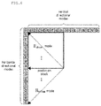
- FIG. 8 is a view showing a left area, an upper area, and a left upper area within a current transform block according to an embodiment of the present invention.
- the left area may be a 1 ⁇ 4 left area 801 or 1 ⁇ 2 left area 802 within a transform block.
- the upper area may be a 1 ⁇ 4 upper area 803 or 1 ⁇ 2 upper area 804 of the transform block.
- the left upper area may be a 1 ⁇ 4 left upper area 805 or 1 ⁇ 2 left upper area 806 of the transform block.
- FIGS. 5 to 8 a case of performing secondary transform in the image encoding apparatus has been described. However, it is not limited thereto, and the image decoding apparatus may determine a secondary inverse-transform performing area by using the same method described above.
- FIG. 9 is a view of a flowchart showing a method of determining a method of determining a transform performing area on the basis of a frequency area of a transform block.
- a low frequency area within a transform block may be determined on the basis of a transform base.
- the low frequency area within the transform block may vary according to a transform base.
- a secondary transform performing area may be determined as the low frequency area within the transform block.
- a frequency range specifying the low frequency area may be identically fixed in the image encoding apparatus and the image decoding apparatus.
- additional information may be transmitted from the image encoding apparatus to the image decoding apparatus so as to determine a frequency range specifying a low frequency area.
- FIG. 10 is a view showing an example of determining a transform performing area on the basis of a frequency area of a transform block.
- a low frequency area of a transform block after primary transform may be a left upper area within the transform block.
- a low frequency area of a transform block after dequantization may be a left upper area within a transform block.
- FIG. 10 a secondary transform performing area is shown under the above assumption.
- the image encoding apparatus/image decoding apparatus may determine a left upper 1/16 area of a transform block as a low frequency area, and determine the corresponding area as a secondary transform performing area.
- the image encoding apparatus/image decoding apparatus transform block may determine a left upper 1 ⁇ 4 area as a low frequency area, and determine the corresponding area as a secondary transform performing area.
- FIGS. 5 to 10 a method of determining a transform performing area for which secondary transform or secondary inverse-transform is performed has been described, but it is not limited thereto.
- a transform performing area for which primary transform or primary inverse-transform is performed may be determined by using the same method.
- the entire transform block may be determined as a transform performing area.
- the image encoding apparatus and the image decoding apparatus may identically determine a secondary transform performing area and a secondary inverse-transform performing area by using the method described above, or information of a secondary transform performing area determined by the method described above may be encoded in the image encoding apparatus and transmitted to the image decoding apparatus.
- the corresponding information may be transmitted in an upper layer level (video layer, sequence layer, picture layer, slice layer, coding block layer, etc.) or in a transform block unit.
- a transform block obtained by partitioning an upper layer transform block is defined as a sub transform block.
- FIGS. 11 and 12 are views showing a QT partition of a transform block.
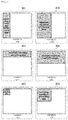
- FIG. 11 is a view of a flowchart showing a method of encoding optimized QT partition information when performing QT partition for a transform block into a sub transform block.
- the entire transform block may mean a transform block having an uppermost partition depth
- a current sub transform block may mean a sub transform block that is currently encoded
- a current partial block may mean a partial block that is currently encoded among partial blocks obtained by partitioning the current sub transform block.
- the entire transform block may be set as a current sub transform block.
- QT partition information in the current sub transform block may be encoded.
- QT partition encoding may be ended.
- S 1104 may be performed.
- a partial block may be generated by performing a QT partition for the current sub transform block.
- QT partition information of the partial block that is currently encoded (hereinafter, referred as current partial block) may be encoded in an encoding order of partial blocks obtained by partitioning the current sub transform block.
- S 1109 may be performed.
- QT partition encoding may be ended.
- the current sub transform block is set as a current partial block having an upper layer depth, and encoding of QT partition information of a partial block having the following encoding order of the current partial block having the upper layer depth is performed by returning to S 1105 .
- the current partial block is set as a current sub transform block having a lower layer depth, and retuning to S 1104 may be performed.
- a maximum/minimum size of a transform block for which a QT partition is available, a maximum depth for which a QT partition is available, a depth for which partition is available in a current transform block, etc. may be identically fixed in the image encoding apparatus and the image decoding apparatus, or the same may be transmitted form the image encoding apparatus to the image decoding apparatus through an upper layer header (slice layer, picture layer, sequence layer, vide layer, etc.).
- FIG. 12 is a view of a flowchart showing a method of performing a QT partition for a transform block into a sub transform block by decoding QT partition information.
- the entire transform block may be set as a current sub transform block.
- QT partition information in the current sub transform block may be decoded.
- QT partition decoding may be ended.
- four partial blocks may be generated by performing a QT partition for the current sub transform block.
- QT partition information of a partial block that is currently decoded (hereinafter, referred as current partial block) may be decoded in a decoding order of partial blocks obtained by partitioning the current sub transform block.
- S 1209 may be performed.
- QT partition decoding may be ended.
- the current sub transform block may be set as a current partial block having an upper layer depth, and decoding of QT partition information of a partial block having the following decoding order of the current partial block having the upper layer depth may be performed by returning to S 1205 .
- the current partial block may be set as a current sub transform block having a lower layer depth, and returning to S 1204 may be performed.
- FIGS. 13 and 14 are views showing a BT partition of a transform block.
- FIGS. 13 and 14 the rest of the process is the same with examples of FIGS. 11 and 12 except that a QT partition is changed to a BT partition and QT partition information is changed to BT partition information. Accordingly, description of FIGS. 13 and 14 will be omitted.
- FIG. 15 is a view showing an example where a transform performing area is partitioned into a partial transform block by using QT partition and BT partition.
- the transform performing area may mean the entire transform block.
- the transform performing area is assumed to be a left upper of a current block.
- 1501 shows a shape of a partial transform block obtained by performing a QT partition method for the entire transform block
- 1502 shows a shape of a partial transform block obtained by performing a BT partition method for the entire transform block
- 1503 shows a shape of a partial transform block obtained by performing a QT partition method and a BT partition method for the entire transform block.
- the image encoding apparatus and the image decoding apparatus may determine a partition shape of a transform block on the basis of a size of the entire transform block within a transform performing area.
- transform when both of horizontal and vertical lengths of the entire transform block are equal to or greater than 8, transform may be perform for a left upper 8 ⁇ 8 sub transform block, otherwise, transform may be perform for a left upper 4 ⁇ 4 sub transform block.
- a shape of a sub transform block partition within a transform performing area may be determined, and transform or inverse-transform may be performed in a sub transform block unit.
- transform or inverse-transform may be performed in a sub transform block unit.
- a coefficient scan method and a resorting method which are possibly performed after or before performing secondary transform within a secondary transform performing area in a sub transform block unit will be described.
- the secondary transform performing area and secondary transform may be a concept including a secondary inverse-transform performing area and secondary inverse-transform.
- FIG. 16 is a view showing an example of a scanning method and a resorting method of a 2D sub transform block when converting a 2D sub transform block to a 1D sub transform block to perform a 1D transform method rather than a 2D transform method.
- 1601 shows a method of resorting a 2D sub transform block, for which primary transform is performed before performing secondary transform, to a 1D sub transform block by scanning the same in a vertical direction.
- a vertical directional scan order may be C 00 , C 10 , C 20 , C 01 , . . . , C 23 , and C 33 , and mapping to a 1D sub transform block may be performed in the same order.
- a horizontal directional scan order may be C 00 , C 01 , C 02 , C 03 , C 10 , . . . , C 32 , and C 33 , and mapping to a 1D sub transform block may be performed in the same order.
- a 45-degree diagonal directional scan order may be C 00 , C 10 , C 01 , C 20 , C 11 , . . . , C 23 , and C 33 , and mapping to a 1D sub transform block may be performed in the same order.
- FIG. 17 is a view showing an example of a scan method and a resorting method of a 2D sub transform block.
- FIG. 17, 1701 show a method of resorting a 2D sub transform block, for which secondary transform is performed, to a 2D sub transform block by scanning the same in a vertical direction after performing secondary transform.
- a vertical directional scan order may be C 00 , C 10 , C 20 , C 01 , . . . , C 23 , and C 33 , and mapping to a 2D sub transform block may be performed in the same order.
- a horizontal directional scan order may be C 00 , C 01 , C 02 , C 03 , C 10 , . . . , C 32 , and C 33 , and mapping to a 2D sub transform block may be performed in the same order.
- a 45-degree diagonal directional scan order may be C 00 , C 10 , C 01 , C 20 , C 11 , . . . , C 23 , and C 33 , and mapping to a 2D sub transform block may be performed in the same order.
- a method shown in FIG. 17 may be performed before performing secondary transform.
- FIGS. 16 and 17 various directional scan methods may be used other than a vertical direction, a horizontal direction, and a 45-degree diagonal direction.
- secondary transform or secondary inverse-transform is used as an example, but the above method may be applied to a case of primary transform and primary inverse-transform.
- a scan method in a coefficient scan method of a sub transform block, and a scan method may be variably performed in a sub transform block unit according to a prediction mode.
- FIG. 18 is a view of a flowchart showing a method of determining a scan method for a sub transform block according to a prediction mode performed when generating a current transform block.
- a prediction mode performed for generating a current transform block is one of horizontal directional prediction mode among intra-prediction modes may be determined.
- a scan method for a sub transform block may be determined as a vertical directional scan method.
- a scan method for a sub transform block may be determined as a horizontal directional scan method.
- a scan method for a sub transform block may be determined as a 45-degree diagonal directional scan method.
- a scan method for a sub transform block may be determined as a 45-degree diagonal directional scan method.
- a scan method in a coefficient scan method for a sub transform block, may be differently performed in a sub transform block unit according to a transform base.
- FIG. 19 is a view showing a method of determining a scan method for a sub transform block according to a transform base.
- a 45-degree diagonal directional scan method may be determined for a left upper sub transform block, and a vertical direction scan method may be determined for remaining sub transform blocks as a sub transform block scan method.
- the image encoding apparatus may determine an optimized scan method for each sub transform block through RDO, and transmit the optimized scan method to the image decoding apparatus by encoding the same.
- FIG. 20 is a view of a flowchart showing an image decoding method according to an embodiment of the present invention.
- the image decoding apparatus may determine a transform performing area.
- the image decoding apparatus may determine the transform performing area on the basis of an intra-prediction mode of a current prediction block in association with a current transform block.
- the image decoding apparatus may determine a left area of the current transform block as the transform performing area when the intra-prediction mode of the current prediction block is a horizontal directional prediction mode, and determine an upper area of the current transform block as the transform performing area when the intra-prediction mode of the current prediction block is a vertical directional prediction mode.
- the image decoding apparatus may determine a left upper area of the current transform block as the transform performing area.
- the image decoding apparatus may determine the transform performing area on the basis of a specific frequency area of the current transform block.
- the specific frequency area may be determined on the basis of a predefined value.
- the image decoding apparatus may perform partition for the determined transform performing area into at least one sub transform block by using at least one of a QT partition and a BT partition.
- the image decoding apparatus may perform inverse-transform for the at least one sub transform block.
- inverse-transform may be any one of primary inverse-transform and secondary inverse-transform.
- the at least one sub transform block may be a 2D sub transform block.
- the image decoding apparatus may further perform: determining a coefficient scan method of the sub transform block; and resorting the 2D sub transform block on the basis of the determined coefficient scan method.
- the image decoding apparatus may determine the coefficient scan method of the sub transform block on the basis of an intra-prediction mode of the current prediction block in association with the current transform block.
- the image decoding method of FIG. 20 may be identically performed in the image encoding apparatus as an image encoding method.
- inverse-transform may be changed to transform.
- an embodiment of the present invention may be achieved by various means, for example, hardware, firmware, software, or a combination thereof.
- an embodiment of the present invention may be achieved by one or more application specific integrated circuits (ASICs), digital signal processors (DSPs), digital signal processing devices (DSDPs), programmable logic devices (PLDs), field programmable gate arrays (FPGAs), processors, controllers, microcontrollers, microprocessors, etc.
- ASICs application specific integrated circuits
- DSPs digital signal processors
- DSDPs digital signal processing devices
- PLDs programmable logic devices
- FPGAs field programmable gate arrays
- processors controllers, microcontrollers, microprocessors, etc.
- the range of the present invention includes software or machine-executable instructions (for example, operating system, application, firmware, program, etc.) so that operation according to various embodiments are executed in an apparatus or computer, and a non-transitory computer-readable medium storing such software or instructions so as to be executable in an apparatus or computer.
- software or machine-executable instructions for example, operating system, application, firmware, program, etc.
- the present invention may be used for an image encoding/deciding apparatus.
Landscapes
- Engineering & Computer Science (AREA)
- Multimedia (AREA)
- Signal Processing (AREA)
- Physics & Mathematics (AREA)
- Discrete Mathematics (AREA)
- General Physics & Mathematics (AREA)
- Compression Or Coding Systems Of Tv Signals (AREA)
Abstract
Description
J(Ø,λ)=D(Ø)+λR(Ø) [Formula 1]
Claims (16)
Applications Claiming Priority (5)
| Application Number | Priority Date | Filing Date | Title |
|---|---|---|---|
| KR10-2016-0133756 | 2016-10-14 | ||
| KR20160133756 | 2016-10-14 | ||
| KR1020170127941A KR102416804B1 (en) | 2016-10-14 | 2017-09-29 | Image encoding method/apparatus, image decoding method/apparatus and and recording medium for storing bitstream |
| KR10-2017-0127941 | 2017-09-29 | ||
| PCT/KR2017/011215 WO2018070788A1 (en) | 2016-10-14 | 2017-10-12 | Image encoding method/device, image decoding method/device and recording medium having bitstream stored therein |
Related Parent Applications (1)
| Application Number | Title | Priority Date | Filing Date |
|---|---|---|---|
| PCT/KR2017/011215 A-371-Of-International WO2018070788A1 (en) | 2016-10-14 | 2017-10-12 | Image encoding method/device, image decoding method/device and recording medium having bitstream stored therein |
Related Child Applications (1)
| Application Number | Title | Priority Date | Filing Date |
|---|---|---|---|
| US17/196,160 Continuation US11659174B2 (en) | 2016-10-14 | 2021-03-09 | Image encoding method/device, image decoding method/device and recording medium having bitstream stored therein |
Publications (2)
| Publication Number | Publication Date |
|---|---|
| US20190335173A1 US20190335173A1 (en) | 2019-10-31 |
| US10979709B2 true US10979709B2 (en) | 2021-04-13 |
Family
ID=62087501
Family Applications (2)
| Application Number | Title | Priority Date | Filing Date |
|---|---|---|---|
| US16/341,830 Active US10979709B2 (en) | 2016-10-14 | 2017-10-12 | Image encoding method/device, image decoding method/device and recording medium having bitstream stored therein |
| US17/196,160 Active 2038-04-15 US11659174B2 (en) | 2016-10-14 | 2021-03-09 | Image encoding method/device, image decoding method/device and recording medium having bitstream stored therein |
Family Applications After (1)
| Application Number | Title | Priority Date | Filing Date |
|---|---|---|---|
| US17/196,160 Active 2038-04-15 US11659174B2 (en) | 2016-10-14 | 2021-03-09 | Image encoding method/device, image decoding method/device and recording medium having bitstream stored therein |
Country Status (3)
| Country | Link |
|---|---|
| US (2) | US10979709B2 (en) |
| KR (1) | KR102416804B1 (en) |
| CN (1) | CN109845256B (en) |
Cited By (1)
| Publication number | Priority date | Publication date | Assignee | Title |
|---|---|---|---|---|
| US20210127112A1 (en) * | 2017-07-04 | 2021-04-29 | Samsung Electronics Co., Ltd. | Image encoding method and apparatus, and image decoding method and apparatus |
Families Citing this family (8)
| Publication number | Priority date | Publication date | Assignee | Title |
|---|---|---|---|---|
| US20190327476A1 (en) * | 2016-06-24 | 2019-10-24 | Industry Academy Cooperation Foundation Of Sejong University | Video signal processing method and device |
| CN112166609B (en) * | 2018-06-08 | 2024-10-18 | 株式会社Kt | Method and apparatus for processing a video signal |
| KR102534160B1 (en) * | 2018-09-02 | 2023-05-26 | 엘지전자 주식회사 | Image coding method based on multiple transform selection and its device |
| EP4664892A3 (en) * | 2018-09-05 | 2026-03-11 | LG Electronics Inc. | Method for encoding/decoding video signal, and apparatus therefor |
| KR20250069986A (en) | 2019-01-01 | 2025-05-20 | 엘지전자 주식회사 | Image coding method based on secondary transform and device therefor |
| CN116781895A (en) | 2019-01-12 | 2023-09-19 | Lg电子株式会社 | Decoding device, encoding device, and image data transmitting device |
| WO2020216303A1 (en) | 2019-04-23 | 2020-10-29 | Beijing Bytedance Network Technology Co., Ltd. | Selective use of secondary transform in coded video |
| WO2021190593A1 (en) | 2020-03-25 | 2021-09-30 | Beijing Bytedance Network Technology Co., Ltd. | Coded video processing using enhanced secondary transform |
Citations (6)
| Publication number | Priority date | Publication date | Assignee | Title |
|---|---|---|---|---|
| WO2012061298A1 (en) | 2010-11-01 | 2012-05-10 | Qualcomm Incorporated | Joint coding of syntax elements for video coding |
| WO2013003743A1 (en) | 2011-06-29 | 2013-01-03 | Qualcomm Incorporated | Multiple zone scanning order for video coding |
| US20130003828A1 (en) | 2011-07-01 | 2013-01-03 | Cohen Robert A | Method for Selecting Transform Types From Mapping Table for Prediction Modes |
| WO2013152401A1 (en) | 2012-04-13 | 2013-10-17 | Canon Kabushiki Kaisha | Method, apparatus and system for encoding and decoding a subset of transform units of encoded video data |
| US20140362926A1 (en) * | 2012-01-19 | 2014-12-11 | Canon Kabushiki Kaisha | Method, apparatus and system for encoding and decoding the significance map for residual coefficients of a transform unit |
| KR20150009503A (en) | 2010-08-17 | 2015-01-26 | 삼성전자주식회사 | Method and apparatus for video encoding using transformation unit in variable tree-structure, method and apparatus for video decoding using transformation unit in variable tree-structure |
Family Cites Families (6)
| Publication number | Priority date | Publication date | Assignee | Title |
|---|---|---|---|---|
| US7822281B2 (en) * | 2003-10-31 | 2010-10-26 | Canon Kabushiki Kaisha | Digital video compression |
| JP2005167655A (en) * | 2003-12-03 | 2005-06-23 | Matsushita Electric Ind Co Ltd | Transform coding method and transform decoding method |
| GB2429593A (en) * | 2005-08-26 | 2007-02-28 | Electrosonic Ltd | Data compressing using a wavelet compression scheme |
| KR101474756B1 (en) * | 2009-08-13 | 2014-12-19 | 삼성전자주식회사 | Method and apparatus for encoding and decoding image using large transform unit |
| WO2011049119A1 (en) * | 2009-10-20 | 2011-04-28 | シャープ株式会社 | Moving image coding device, moving image decoding device, moving image coding/decoding system, moving image coding method and moving image decoding method |
| WO2012161445A2 (en) * | 2011-05-20 | 2012-11-29 | 주식회사 케이티 | Decoding method and decoding apparatus for short distance intra prediction unit |
-
2017
- 2017-09-29 KR KR1020170127941A patent/KR102416804B1/en active Active
- 2017-10-12 CN CN201780063400.9A patent/CN109845256B/en active Active
- 2017-10-12 US US16/341,830 patent/US10979709B2/en active Active
-
2021
- 2021-03-09 US US17/196,160 patent/US11659174B2/en active Active
Patent Citations (9)
| Publication number | Priority date | Publication date | Assignee | Title |
|---|---|---|---|---|
| KR20150009503A (en) | 2010-08-17 | 2015-01-26 | 삼성전자주식회사 | Method and apparatus for video encoding using transformation unit in variable tree-structure, method and apparatus for video decoding using transformation unit in variable tree-structure |
| WO2012061298A1 (en) | 2010-11-01 | 2012-05-10 | Qualcomm Incorporated | Joint coding of syntax elements for video coding |
| KR20130084308A (en) | 2010-11-01 | 2013-07-24 | 퀄컴 인코포레이티드 | Joint coding of syntax elements for video coding |
| WO2013003743A1 (en) | 2011-06-29 | 2013-01-03 | Qualcomm Incorporated | Multiple zone scanning order for video coding |
| KR101607782B1 (en) | 2011-06-29 | 2016-03-30 | 퀄컴 인코포레이티드 | Multiple zone scanning order for video coding |
| US20130003828A1 (en) | 2011-07-01 | 2013-01-03 | Cohen Robert A | Method for Selecting Transform Types From Mapping Table for Prediction Modes |
| US20140362926A1 (en) * | 2012-01-19 | 2014-12-11 | Canon Kabushiki Kaisha | Method, apparatus and system for encoding and decoding the significance map for residual coefficients of a transform unit |
| WO2013152401A1 (en) | 2012-04-13 | 2013-10-17 | Canon Kabushiki Kaisha | Method, apparatus and system for encoding and decoding a subset of transform units of encoded video data |
| KR20140126370A (en) | 2012-04-13 | 2014-10-30 | 캐논 가부시끼가이샤 | Method, apparatus and system for encoding and decoding a subset of transform units of encoded video data |
Non-Patent Citations (1)
| Title |
|---|
| International Search Report dated Jan. 22, 2018 in corresponding International Application No. PCT/KR2017/011215 (3 pages in English, 3 pages in Korean). |
Cited By (1)
| Publication number | Priority date | Publication date | Assignee | Title |
|---|---|---|---|---|
| US20210127112A1 (en) * | 2017-07-04 | 2021-04-29 | Samsung Electronics Co., Ltd. | Image encoding method and apparatus, and image decoding method and apparatus |
Also Published As
| Publication number | Publication date |
|---|---|
| US20210195191A1 (en) | 2021-06-24 |
| CN109845256B (en) | 2023-09-01 |
| CN109845256A (en) | 2019-06-04 |
| KR20180041578A (en) | 2018-04-24 |
| US11659174B2 (en) | 2023-05-23 |
| US20190335173A1 (en) | 2019-10-31 |
| KR102416804B1 (en) | 2022-07-05 |
Similar Documents
| Publication | Publication Date | Title |
|---|---|---|
| US11659174B2 (en) | Image encoding method/device, image decoding method/device and recording medium having bitstream stored therein | |
| CN111886861B (en) | Image decoding method and apparatus according to block division structure in image coding system | |
| US9609353B2 (en) | Apparatus for encoding a moving picture | |
| CA2997097C (en) | Method and device for processing video signal | |
| CN106416254B (en) | Skip the evaluation phase during media encoding | |
| CA2968598C (en) | Method for deriving a merge candidate block and device using same | |
| KR102061201B1 (en) | Methods of transformation based on block information and appratuses using the same | |
| US12244801B2 (en) | Image encoding method/device, image decoding method/device and recording medium having bitstream stored therein | |
| JP6355715B2 (en) | Encoding device, decoding device, encoding method, decoding method, and program | |
| KR20180061027A (en) | Method and apparatus for encoding/decoding image and recording medium for storing bitstream | |
| KR101468078B1 (en) | Method and apparatus for intra prediction | |
| KR20130085392A (en) | Method and apparatus for encoding and decoding video to enhance intra prediction process speed | |
| US20210250596A1 (en) | Image encoding/decoding method and device | |
| KR102425722B1 (en) | Method and apparatus for encoding/decoding a video signal | |
| US20250175653A1 (en) | Method and apparatus for encoding/decoding image | |
| KR20240124260A (en) | Method and apparatus for encoding/decoding an image | |
| US20220224932A1 (en) | Image encoding/decoding method and device, and recording medium storing bitstream | |
| KR20200087088A (en) | Image encoding/decoding method and apparatus | |
| CN110771166B (en) | Intra-frame prediction device and method, encoding device, decoding device, and storage medium | |
| US20200029079A1 (en) | Method for processing image providing improved arithmetic encoding, method for decoding and encoding image using same, and apparatus for same | |
| KR102410326B1 (en) | Method and apparatus for encoding/decoding a video signal | |
| KR20200087086A (en) | Method and apparatus for encoding/decoding an image | |
| KR102912000B1 (en) | Image encoding method/apparatus, image decoding method/apparatus and recording medium for storing bitstream | |
| KR20240165861A (en) | Method for Intra Prediction Based on Extrapolation |
Legal Events
| Date | Code | Title | Description |
|---|---|---|---|
| AS | Assignment |
Owner name: INDUSTRY ACADEMY COOPERATION FOUNDATION OF SEJONG Free format text: ASSIGNMENT OF ASSIGNORS INTEREST;ASSIGNORS:MOON, JOO HEE;WON, DONG JAE;LIM, SUNG WON;REEL/FRAME:048875/0434 Effective date: 20190410 Owner name: INDUSTRY ACADEMY COOPERATION FOUNDATION OF SEJONG UNIVERSITY, KOREA, REPUBLIC OF Free format text: ASSIGNMENT OF ASSIGNORS INTEREST;ASSIGNORS:MOON, JOO HEE;WON, DONG JAE;LIM, SUNG WON;REEL/FRAME:048875/0434 Effective date: 20190410 |
|
| FEPP | Fee payment procedure |
Free format text: ENTITY STATUS SET TO UNDISCOUNTED (ORIGINAL EVENT CODE: BIG.); ENTITY STATUS OF PATENT OWNER: SMALL ENTITY |
|
| FEPP | Fee payment procedure |
Free format text: ENTITY STATUS SET TO SMALL (ORIGINAL EVENT CODE: SMAL); ENTITY STATUS OF PATENT OWNER: SMALL ENTITY |
|
| STPP | Information on status: patent application and granting procedure in general |
Free format text: RESPONSE TO NON-FINAL OFFICE ACTION ENTERED AND FORWARDED TO EXAMINER |
|
| STPP | Information on status: patent application and granting procedure in general |
Free format text: NOTICE OF ALLOWANCE MAILED -- APPLICATION RECEIVED IN OFFICE OF PUBLICATIONS |
|
| STPP | Information on status: patent application and granting procedure in general |
Free format text: PUBLICATIONS -- ISSUE FEE PAYMENT RECEIVED |
|
| STPP | Information on status: patent application and granting procedure in general |
Free format text: PUBLICATIONS -- ISSUE FEE PAYMENT VERIFIED |
|
| STCF | Information on status: patent grant |
Free format text: PATENTED CASE |
|
| MAFP | Maintenance fee payment |
Free format text: PAYMENT OF MAINTENANCE FEE, 4TH YR, SMALL ENTITY (ORIGINAL EVENT CODE: M2551); ENTITY STATUS OF PATENT OWNER: SMALL ENTITY Year of fee payment: 4 |
|
| FEPP | Fee payment procedure |
Free format text: ENTITY STATUS SET TO UNDISCOUNTED (ORIGINAL EVENT CODE: BIG.); ENTITY STATUS OF PATENT OWNER: LARGE ENTITY |
|
| MAFP | Maintenance fee payment |
Free format text: PAYMENT OF MAINTENANCE FEE UNDER 1.28(C) (ORIGINAL EVENT CODE: M1559); ENTITY STATUS OF PATENT OWNER: LARGE ENTITY |