US10976484B2 - Frame structure, backlight assembly and display device - Google Patents
Frame structure, backlight assembly and display device Download PDFInfo
- Publication number
- US10976484B2 US10976484B2 US16/447,754 US201916447754A US10976484B2 US 10976484 B2 US10976484 B2 US 10976484B2 US 201916447754 A US201916447754 A US 201916447754A US 10976484 B2 US10976484 B2 US 10976484B2
- Authority
- US
- United States
- Prior art keywords
- annular bottom
- sidewall
- protrusion
- notch
- hollow portion
- Prior art date
- Legal status (The legal status is an assumption and is not a legal conclusion. Google has not performed a legal analysis and makes no representation as to the accuracy of the status listed.)
- Expired - Fee Related
Links
Images


Classifications
-
- G—PHYSICS
- G02—OPTICS
- G02B—OPTICAL ELEMENTS, SYSTEMS OR APPARATUS
- G02B6/00—Light guides; Structural details of arrangements comprising light guides and other optical elements, e.g. couplings
- G02B6/0001—Light guides; Structural details of arrangements comprising light guides and other optical elements, e.g. couplings specially adapted for lighting devices or systems
- G02B6/0011—Light guides; Structural details of arrangements comprising light guides and other optical elements, e.g. couplings specially adapted for lighting devices or systems the light guides being planar or of plate-like form
- G02B6/0081—Mechanical or electrical aspects of the light guide and light source in the lighting device peculiar to the adaptation to planar light guides, e.g. concerning packaging
- G02B6/0086—Positioning aspects
- G02B6/0088—Positioning aspects of the light guide or other optical sheets in the package
Definitions
- At least one embodiment of the present disclosure relates to a frame structure, a backlight assembly and a display device.
- the liquid crystal display device usually includes a backlight assembly and a display panel. By applying a voltage to the display panel, an electric field is formed in the display panel to drive liquid crystal molecules to rotate, so as to control transmission or shielding of light emitted from the backlight assembly, thereby realizing image display.
- the existing backlight assembly, the frame structure for forming the backlight assembly, and the display device including the backlight assembly are still to be improved.
- a first aspect of the present disclosure provides a frame structure, the frame structure includes: a frame including an annular bottom and a sidewall surrounding the annular bottom, the annular bottom has a protrusion disposed in parallel with the sidewall; and a matching plate having a first hollow portion, the first hollow portion is configured to be engaged with the protrusion.
- a second aspect of the present disclosure provides a backlight assembly including the frame structure according to the first aspect.
- a third aspect of the present disclosure provides a display device including the backlight assembly according to the second aspect.
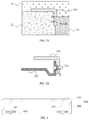
- FIG. 1A and FIG. 1B are schematic structural views of a backlight assembly
- FIG. 2A and FIG. 2B are schematic diagrams illustrating the backlight assembly of FIG. 1 generating debris
- FIG. 3 is a schematic structural view of a frame structure according to an embodiment of the present disclosure.
- FIG. 4 is a schematic structural view of a frame forming mold according to an embodiment of the present disclosure.
- FIG. 5 is a schematic structural view of a frame according to an embodiment of the present disclosure.
- FIG. 6 is a top view of a frame according to an embodiment of the present disclosure.
- FIG. 7 is an enlarged view of a portion indicated by a circle drawn in dashed line of FIG. 6 ;
- FIG. 8A and FIG. 8B illustrate cross-sectional views of the frame taken along a B-B′ line and a C-C′ line in FIG. 6 , respectively;
- FIG. 9 is a plan view of a frame structure according to an embodiment of the present disclosure.
- FIG. 10 is a schematic structural view illustrating an engagement between a matching plate and a protrusion according to an embodiment of the present disclosure
- FIG. 11A and FIG. 11B are plan views of a frame structure according to an embodiment of the present disclosure.
- FIG. 12A and FIG. 12B are schematic structural views of a backlight assembly according to an embodiment of the present disclosure.
- FIG. 13 is a plan view of an optical module according to an embodiment of the present disclosure.
- FIG. 14A , FIG. 14B and FIG. 14C are schematic views illustrating an assembling process of a backlight assembly according to an embodiment of the present disclosure.
- FIG. 15A , FIG. 15B and FIG. 15C are schematic views illustrating an assembling process of another backlight assembly according to an embodiment of the present disclosure.
- FIG. 1A and FIG. 1B illustrate a backlight assembly, in which FIG. 1A is a lateral cross-sectional view of the backlight assembly, and FIG. 1B is a front cross-sectional view of the backlight assembly.
- the backlight assembly includes a frame 100 , an optical film unit 200 , a back plate 300 , and a light bar 400 .
- the optical film unit 200 and the light bar 400 are both disposed in an accommodating space defined by the frame 100 and the back plate 300 , and the light bar 400 is attached to a sidewall of the back plate 300 by a fixing tape 500 .
- the above backlight assembly mainly has the following drawbacks.
- the back plate 300 is usually formed of a galvanized steel sheet (EGI) with a density of about 7.85 g/cm3.
- EPI galvanized steel sheet
- the back plate 300 has a matching structure 310 to be engaged with the frame 100 . Due to the presence of the matching structure 310 , an area of the back plate 300 corresponding to the optical film unit 200 needs to be arched toward the optical film unit 200 to ensure the flatness of the optical film unit 200 and also to support the optical film unit 200 . Therefore, the overall thickness of the backlight assembly includes not only the thickness of the frame 100 , the thickness of the optical film unit 200 , and the thickness of the back plate 300 , but also includes the distance that the back plate 300 is arched (e.g., h 1 as illustrated in FIG. 1A ). As a result, the overall thickness of the backlight assembly is relatively large.
- the frame 100 is formed by injection molding. Because the frame 100 has a hollow portion in a region where the matching structure 310 is engaged, when forming the frame 100 by the injection molding, in addition to the use of a female mold kernel 10 and a male mold kernel 20 , a slider 30 is also required. The slider 30 can make a reciprocating motion in the direction of the arrow illustrated in FIG. 2A so as to form the frame 100 .
- burrs are easily to be generated at junctions A and B of the slider 30 and the male mold kernel 20 , and the burrs cannot be avoided by designing a rounding corner at the parting surface or by other means.
- the back plate 300 and the matching structure 310 on the back plate 300 are formed by a stamping process, and burrs are easily to be generated at the corners or the tip end (for example, the end point C illustrated in FIG. 2B ) during the stamping process.
- the tip end of the frame 100 and the tip end of the matching structure 310 may be scraped.
- the tip end B of the frame 100 and the tip end C of the matching structure 310 may be scraped, resulting in the generation of debris, which will fall into the backlight assembly. It is difficult to find the above-mentioned debris in a conventional inspection, but after a vibration occurs during transportation, the above-mentioned debris may move into a screen of the backlight assembly, causing display failure on the display screen.
- An aspect of the present disclosure provides a frame structure applicable to a backlight assembly, so that the backlight assembly has a thinner thickness and a lighter weight, and can effectively prevent the generation of debris in the engagement process and improve the display quality of a display device.
- a frame structure includes: a frame 100 and a matching plate 600 .
- the frame 100 includes an annular bottom 110 and a sidewall 120 surrounding the annular bottom 110 .
- the annular bottom 110 has a projection 130 disposed in parallel with the sidewall 120 .
- the matching plate 600 has a first hollow portion 40 matched with the projection 130 .
- the matching plate 600 and the frame 100 are engaged with each other.
- Components of the frame structure of the present disclosure will be schematically illustrated by several specific embodiments. Those skilled in the art should understand that the frame structure of the present disclosure is not limited to these specific embodiments.
- the annular bottom 110 of the frame 100 includes a protrusion 130
- the matching plate 600 includes a first hollow portion 40 matched with the protrusion 130 .
- the matching plate can be fixed on the frame by the first hollow portion engaged with the protrusion, so as to achieve an engagement between the matching plate and the frame.
- the frame 100 includes an annular bottom 110 , a sidewall 120 , and a protrusion 130 ; thus, the frame has a simple structure, can be formed with a simple mold, and would not generate burrs. For example, referring to FIG.
- a male mold kernel 20 and a female mold kernel 10 are used to form a mold cavity having the same shape as the frame 100 , and corners of the mold cavity are located inside the male mold kernel 20 (for example, the corners D and E illustrated in FIG. 4 ) or located inside the female mold kernel 10 (for example, the corner F illustrated in FIG. 4 ); that is, the corners of the mold cavity are not located at the junctions of the two molds. Therefore, no burrs would be generated during the injection molding process, and no debris would be generated when the matching plate is engaged with the frame.
- the sidewall 120 of the frame 100 includes a first sidewall 120 A having a second hollow portion 50 and a bent portion 121 disposed in parallel with the annular bottom 110 .
- the protrusion 130 is located on a portion of the annular bottom 110 that is not directly connected to the first sidewall 120 A having the second hollow portion 50 .
- the annular bottom 110 includes a first portion 110 A directly connected to the first sidewall 120 A and a second portion 110 B not directly connected to the first sidewall 120 A.
- the first portion 110 A is not provided with a protrusion 130 .
- the second portion 110 B is provided with a protrusion 130 .
- a light bar can be attached to the first sidewall provided with the second hollow portion, and light emitted by the light bar is irradiated onto an optical film unit in the backlight assembly through the second hollow portion, so as to achieve the use of the backlight assembly; the portion of the annular bottom directly connected to the first sidewall having the second hollow portion is not provided with a protrusion, which can prevent light emitted from the light bar disposed on the first sidewall having the second hollow portion from being shielded by a protrusion, so as to make full use of the light emitted from the light bar.
- the bent portion can be utilized to play a fixing effect on the optical film unit disposed at the first sidewall.
- the first sidewall 120 A having the bent portion 121 further has a second hollow portion 50 , and the second hollow portion 50 is located inside the first sidewall 120 A (as illustrated in FIG. 6 ). That is to say, the second hollow portion 50 is not disposed at an edge of the first sidewall 120 A. Therefore, when forming the first sidewall 120 A by an injection molding process, it needs to form the second hollow portion 50 by means of a slider.
- the frame structure in the present embodiment utilizes a slider to form the sidewall like the frame structure illustrated in FIG. 1 , no debris would be generated because, unlike the situation of FIG. 2A and FIG. 2B , the first sidewall 120 A is not to be engaged with the matching plate 600 , and the display quality of the display device to which the frame is applied will not be affected.
- the annular bottom 110 has a rectangular annular shape, and has four sides 111 - 114 .
- a first side 111 is connected to the first sidewall 120 A having the second hollow portion 50 ; a second side 112 and a third side 113 are adjacent to the first side 111 , respectively; and a fourth side 114 is opposite to the first side 111 .
- Three sides 112 - 114 of the annular bottom 110 i.e., the sides excluding the first side 111 ) each include a protrusion 130 .
- the protrusions 130 on the second side 112 and the third side 113 adjacent to the first side 111 each have a notch 60 (as illustrated in FIG.
- opening directions of the notches 60 are the same with each other, to ensure that the matching plate can be engaged in the same direction.
- the same opening direction of the notches 60 is an extending direction of the second side 112 and the third side 113 , so that the matching plate can be engaged in a direction parallel to the annular bottom to constitute the frame structure.
- FIG. 5 is a cross-sectional view of the frame 100 of FIG. 6 taken along line A-A′.
- the aforementioned first portion 110 A of the annular bottom is the first side 111 of the annular bottom, which is directly connected to the first sidewall 120 A having the second hollow portion 50 ;
- the second portion 110 B opposite to the first portion 110 A is the fourth side 114 of the annular bottom, on which the protrusion 130 is disposed.
- FIGS. 8A-8B are cross-sectional views of the frame 100 of FIG. 6 taken along line B-B′ and line C-C′, respectively. As illustrated in FIGS.
- the second side 112 and the third side 113 adjacent to the first side 111 of the annular bottom 110 each include a protrusion 130 , and the protrusions 130 on the two sides each have a notch 60 .
- the matching plate can be engaged with the protrusion through the notch in the protrusion, so that the matching plate and the frame remain fixed in a direction from the frame to the matching plate (i.e., the direction of the frame facing towards the matching plate).
- the protrusion 130 is provided with a notch 60 , and the notch 60 is disposed at an edge of the protrusion 130 (as illustrated in FIG. 7 ), thus the frame 100 including the protrusion 130 provided with the notch 60 can still be formed by using only a male mold kernel 20 and a female mold kernel 10 (as illustrated in FIG. 4 ).
- it only needs to form a boss having a shape of the notch 60 in a mold cavity of the male mold kernel 20 for forming the projection 130 ; that is to say, corners of the mold cavity for forming the frame 100 including the notch 60 are not located at the junctions of the two molds, so that no burrs would be generated during the injection molding process. Therefore, when the matching plate is engaged with the frame having the notch, no debris would be generated, and the display quality of a display device to which the frame is applied would not be affected.
- the matching plate 600 may be a U-shaped matching plate, and an opening of the U-shaped matching plate is configured to face the first sidewall 120 A having the second hollow portion 50 .
- the engagement between the matching plate and the frame can be achieved by the engagement between the matching plate and the annular bottom provided with the protrusion.
- the U-shaped matching plate can further reduce the weight of the entire backlight assembly as compared with a matching plate having a closed shape such as a rectangular shape, a circular shape, or the like.
- the U-shaped matching plate has two lateral edges 610 and one bottom edge 620 , each of the lateral edges 610 and the bottom edge 620 has a first hollow portion.
- the first hollow portions 40 A on the lateral edges 610 are matched with the protrusions 130 on the second side 112 and the third side 113 of the annular bottom 110 , respectively; and the first hollow portion 40 B on the bottom edge 620 is matched with the projection 130 on the fourth side 114 of the annular bottom 110 . This is favorable for the engagement between the matching plate and the frame.
- each of the sides 112 - 114 of the rectangular annular bottom 110 except the first side 111 has a plurality of protrusions 130 , and the first hollow portions 40 A on the lateral edges 610 of the U-shaped matching plate are engaged with the notches 60 on the second side 112 and the third side 113 (as illustrated in FIG. 10 ), respectively.
- the frame and the matching plate having been engaged with each other can remain fixed in a direction from the annular bottom to the matching plate (i.e., the direction of the annular bottom facing towards the matching plate).
- the first hollow portion 40 B at the bottom edge 620 of the U-shaped matching plate is sleeved onto the protrusion 130 of the fourth side 114 opposite to the first side 111 . In this way, the frame and the matching plate having been engaged with each other can remain fixed in a direction parallel to the annular bottom.
- the second side and the third side of the annular bottom are engaged with the matching plate by means of the protrusion having the notch, so that the frame and the matching plate can be fixed in the direction from the frame to the matching plate (i.e., the direction of the frame facing towards the matching plate).
- the first hollow portion on the bottom edge of the U-shaped matching plate is sleeved onto the protrusion of the fourth side of the annular bottom, so that the frame and the matching plate can maintain as being fixed in a direction parallel to the annular bottom.
- the first sidewall having the second hollow portion in the frame has a bent portion disposed in parallel with the annular bottom, and the bent portion can ensure that the frame structure remains fixed at the first sidewall. In this way, it is ensured that the frame has good stability on each side.
- the arrangement of the plurality of protrusions is not particularly limited as long as the engagement between the frame and the matching plate can be realized.
- the plurality of protrusions may be arranged in a straight line or a fold line along an extending direction of each of the sides, and the corresponding first hollow portions on the matching plate are also arranged in a straight line or in a fold line, so as to be matched with the corresponding protrusions to complete the engagement.
- the shape of the protrusion is not particularly limited as long as the engagement between the frame and the matching plate can be achieved, and those skilled in the art can design according to the specific conditions.
- the protrusion may have a rectangular parallelepiped shape, a triangular shape, a square shape, or the like, and the shape of the corresponding first hollow portion on the matching plate also has a rectangular parallelepiped shape, a triangular shape, a square shape, etc., respectively, to be matched with the corresponding protrusion, so as to complete the engagement.
- the number and the size of the protrusions are not particularly limited as long as the engagement between the matching plate and the frame can be achieved, and the annular bottom and the sidewalls can be matched as described above. Those skilled in the art can design according to the specific conditions.
- the matching plate 600 is disposed opposite to the frame 100 in such a manner that orthographic projections of the first hollow portions 40 A on the two lateral edges 610 of the matching plate 600 on the annular bottom 110 cover the protrusions 130 on the second side 112 and the third side 113 (as illustrated in FIG.
- the first hollow portions 40 A on the two lateral edges 610 of the matching plate 600 are sleeved onto the protrusions 130 on the second side 112 and the third side 113 of the annular bottom 110 respectively; subsequently, the matching plate 600 is pulled to move along a direction from the fourth side 114 to the first side 111 of the annular bottom 110 , or the matching plate 600 is pulled to move along a direction from the first side 111 to the fourth side 114 of the annular bottom 110 , such that the two lateral edges 610 of the matching plate 600 are engaged with the notches 60 of the protrusions 130 of the second side 112 and the third side 113 of the annular bottom 110 respectively, and the first hollow portion 40 B on the bottom edge 620 of the matching plate 600 is sleeved onto the projection 130 of the fourth side 114 of the annular bottom 110 at the same time.
- the frame structure as obtained after the engagement between the matching plate 600 and the frame 100 is as illustrated in FIG. 9 . In this way, the
- the thickness of the matching plate 600 is not greater than the height of the notch 60 in the protrusion 130 (h 2 as illustrated in FIG. 7 ), so as for engaging the matching plate with the notch, thereby implementing the engagement between the matching plate and the frame.
- the protrusion 130 on the second side 112 and the third side 113 located closer to the first side 111 , and the protrusion 130 on the fourth side 114 have a distance L1 there-between.
- the first hollow portions 40 A on the two lateral edges 610 of the matching plate 600 are sleeved onto the protrusions 130 on the second side 112 and the third side 113 of the annular bottom 110 , respectively.
- the first hollow portion 40 A on the two lateral edges 610 of the matching plate 600 closer to the first sidewall 120 A having the second hollow portion 50 , and the first hollow portion 40 B on the bottom edge 620 of the matching plate 600 has a distance L2 therebetween; and the first hollow portion 40 B on the bottom edge 620 and the protrusion 130 on the fourth side 114 of the annular bottom 110 has a distance L3 therebetween.
- a distance that the matching plate 600 moves in the extending direction of the second side 112 of the annular bottom 110 is L3
- a maximum distance that the matching plate 600 can move in the extending direction of the second side 112 is the length of the notch 60 (L4 as illustrated in FIG. 7 ), that is, L3 ⁇ L4.
- the distance between the first hollow portions on the lateral edges and the bottom edge of the matching plate can be obtained according to the distance between the protrusions on the second side and the fourth side of the annular bottom, as well as the length of the notch, so as to obtain dimension parameters related to the matching plate engaged with the frame.
- the backlight assembly includes the frame structure described in any of the abovementioned embodiments or examples.
- the backlight assembly has all the features and advantages of the frame structure described above, and details are omitted herein.
- the backlight assembly has smaller thickness and weight, and can effectively avoid the generation of the debris and improve the display quality of display device.
- the backlight assembly utilizes the above-described protrusion on the frame to achieve the engagement with the matching plate, which saves a back plate and a matching structure on the back plate in the backlight assembly illustrated in FIG. 1-2 .
- the weight of the backlight assembly is significantly reduced; and no debris would be generated during the engagement by using the frame and the matching plate as described above, thereby improving the display quality of the display device to which the backlight assembly is applied.
- the principle that no debris is generated upon the frame and the matching plate being engaged with each other has been described in detail above and will not be repeated herein.
- the backlight assembly includes a frame 100 , an optical film unit 200 , a light bar 400 , and a matching plate 600 .
- a first sidewall 120 A of the frame 100 has a second hollow portion 50 and a bent portion 121 ; the light bar 400 is attached to an outer side of the first sidewall 120 A by a fixing tape 500 , which facilitates the assembly of the light bar.
- the protrusion 130 is only disposed on a portion of the annular bottom 110 that is not connected to the first sidewall 120 A, that is, a portion of the annular bottom that is connected to the first sidewall to which the light bar is attached is not provided with a protrusion, thereby preventing light emitted by the light bar from being shielded by the protrusion;
- the sidewall of the frame 100 not provided with the second hollow portion 50 each has a notch 70 on a side away from the annular bottom 110 .
- the matching plate 600 extends into the notch 70 , thereby preventing light leakage and improving the utilization of light emitted by the light bar.
- the first portion 110 A of the annular bottom 110 provided with the light bar 400 may extend along a direction away from the first sidewall 120 A, and the extending portion is matched with the light bar 400 , such that the light bar 400 is fixed to an area formed by the extending portion and the first sidewall 120 A to ensure the fixing stability of the light bar.
- the annular bottom 110 has four sides 111 - 114 , the first side 111 is connected to the first sidewall 120 A, and the second side 112 and the third side 113 are both adjacent to the first side 111 , the fourth side 114 is disposed opposite to the first side 111 .
- Three sides 112 - 114 of the annular bottom 110 i.e., the sides excluding the first side 111 ) each have a protrusion 130 .
- the second portion 110 B i.e., the fourth side 114
- the third portion 110 C i.e., the second side 112
- the fourth portion 110 D i.e., the third side 113
- the opening directions of the notches 60 may be the same with each other, and the same opening direction may be the extending direction of the second side 112 and the third side 113 .
- the optical film unit 200 has a third hollow portion 80 matched with the protrusion 130 , and a side of the optical film unit 200 that is not provided with the third hollow portion 80 is close to the first sidewall 120 A provided with the second hollow portion 50 .
- the optical film unit 200 can be fixed between the annular bottom 110 and the matching plate 600 , whereby the fixation of the optical film unit in a direction parallel to the annular bottom can be achieved.
- the thickness of the optical film unit 200 is d1
- the vertical distance between a side of the notch 60 close to the annular bottom 110 and the annular bottom 110 is d2
- the optical film unit 200 may include an optical film, a light guide plate, and a reflective sheet which are sequentially stacked, and the optical film is disposed close to the annular bottom, whereby the use function of the backlight assembly can be achieved.
- the optical film unit 200 has a third hollow portion 80 matched with a protrusion 130 on the annular bottom 110 ; that is, the optical film, the light guide plate, and the reflective sheet each include a third hollow portion matched with the protrusion, so as to facilitate the assembly and fixation of the above components.
- the overall thickness of the backlight assembly is a sum of the thicknesses of the annular bottom 110 and the thicknesses of the protrusion 130 , while the thickness of the protrusion 130 is determined by the thickness of the optical film unit 200 and the thickness of the matching plate 600 .
- the thickness of the matching plate 600 is not greater than the height of the notch 60 .
- the height of the notch 60 may be set to be as same as the thickness of the matching plate 600 .
- the thickness of the matching plate 600 in the embodiment of the present disclosure may be equal to the thickness of the back plate in the backlight assembly illustrated in FIGS. 1-2 , for example, may be 0.8 mm, whereby the height of the notch 60 can be determined.
- the thickness of a portion of the protrusion 130 on a side of the notch 60 away from the annular bottom 110 may be configured such that the matching plate 600 remains fixed in a direction from the annular bottom to the matching plate (i.e., the direction of the annular bottom facing towards the matching plate). Based on this, those skilled in the art can select a suitable thickness, as small as possible, for this portion. Then, the thickness of the other portions of the projection 130 can be determined.
- the overall thickness of the backlight assembly is a sum of thicknesses of all the components, and because the embodiment of the present disclosure eliminates the thickness (about 1.5 mm) of the arched portion of the back plate (h 1 as illustrated in FIG. 2A and FIG. 2B ), the thickness of the backlight assembly of the embodiment of the present disclosure is remarkably reduced, and has the advantage of smaller thickness and weight, which is favorable for the development of a thinner and lighter display device.
- the backlight assembly is assembled in a reversed manner.
- the optical film 210 is disposed in the frame 100 in such a manner that the third hollow portions 80 of the optical film 210 are sleeved onto the protrusion (not illustrated) on the second side 112 (not illustrated), the protrusion 130 A on the third side 113 (not illustrated), and the protrusion 130 B on the fourth side 114 of the annular bottom 110 , respectively.
- the protrusion 130 A on the second side 112 (not illustrated)
- the protrusion 130 A on the third side 113
- the protrusion 130 B on the fourth side 114 of the annular bottom 110 , respectively.
- the light guide plate 220 is disposed on a side of the optical film 210 away from the annular bottom 110 in such a manner that the third hollow portions 80 of the light guide plate 220 are sleeved onto the protrusion (not illustrated) on the second side 112 (not illustrated), the protrusion 130 A on the third side 113 (not illustrated), and the protrusion 130 B on the fourth side 114 , respectively. Subsequently, referring to FIG.
- the reflective sheet 230 is disposed on a side of the light guide plate 220 in the frame 100 away from the optical film 210 in such a manner that the third hollow portions 80 of the reflective sheet 230 are sleeved onto the protrusion (not illustrated) on the second side 112 (not illustrated), the protrusion 130 A on the third side 113 (not illustrated), and the protrusion 130 B on the fourth side 114 , respectively.
- a sum of the thickness of the optical film 210 , the thickness of the light guide plate 220 , and the thickness of the reflective sheet 230 is equal to the vertical distance between the notch 60 of the protrusion 130 and the annular bottom 110 .
- the first hollow portions 40 A of the two lateral edges of the matching plate 600 are sleeved onto the protrusion (not illustrated) of the second side 112 (not illustrated) and the protrusion 130 A of the third side 113 , respectively, and the matching plate 600 is pulled to move along the extending direction of the third side 113 (i.e., the side where the projection 130 A is located).
- FIG. 15B after the matching plate 600 is engaged with the notch 60 in the protrusion 130 A, the first hollow portion 40 B on the bottom edge of the matching plate 600 is sleeved onto the protrusion 130 B of the fourth side 114 .
- the light bar 400 is attached to an outer side of the first sidewall 120 A provided with the second hollow portion 50 to complete the assembly of the backlight assembly.
- a backlight assembly having smaller thickness and weight can be obtained, and the backlight assembly would not generate debris from engagement during assembly, and the display quality of the display device to which the backlight assembly is applied can be improved.
- the display device includes the backlight assembly described in any of the abovementioned embodiments or examples.
- the display device has all of the features and advantages of the backlight assembly described above, and will not be described herein.
- the display device has smaller thickness and weight, and achieves higher display quality.
Landscapes
- Physics & Mathematics (AREA)
- General Physics & Mathematics (AREA)
- Optics & Photonics (AREA)
- Planar Illumination Modules (AREA)
Abstract
Description
Claims (18)
Applications Claiming Priority (2)
| Application Number | Priority Date | Filing Date | Title |
|---|---|---|---|
| CN201821790804.6U CN208888532U (en) | 2018-10-31 | 2018-10-31 | Framework, backlight assembly, display device |
| CN201821790804.6 | 2018-10-31 |
Publications (2)
| Publication Number | Publication Date |
|---|---|
| US20200132921A1 US20200132921A1 (en) | 2020-04-30 |
| US10976484B2 true US10976484B2 (en) | 2021-04-13 |
Family
ID=66517706
Family Applications (1)
| Application Number | Title | Priority Date | Filing Date |
|---|---|---|---|
| US16/447,754 Expired - Fee Related US10976484B2 (en) | 2018-10-31 | 2019-06-20 | Frame structure, backlight assembly and display device |
Country Status (2)
| Country | Link |
|---|---|
| US (1) | US10976484B2 (en) |
| CN (1) | CN208888532U (en) |
Cited By (1)
| Publication number | Priority date | Publication date | Assignee | Title |
|---|---|---|---|---|
| US20220155640A1 (en) * | 2020-11-19 | 2022-05-19 | Radiant(Guangzhou) Opto-Electronics Co., Ltd. | Frame assembly, backlight module, and display device |
Citations (1)
| Publication number | Priority date | Publication date | Assignee | Title |
|---|---|---|---|---|
| US7106393B2 (en) * | 2002-05-28 | 2006-09-12 | Samsung Electronics Co., Ltd. | Backlight having optical sheet coupled to sheet fixing protrusion and liquid crystal display having the same |
-
2018
- 2018-10-31 CN CN201821790804.6U patent/CN208888532U/en not_active Expired - Fee Related
-
2019
- 2019-06-20 US US16/447,754 patent/US10976484B2/en not_active Expired - Fee Related
Patent Citations (1)
| Publication number | Priority date | Publication date | Assignee | Title |
|---|---|---|---|---|
| US7106393B2 (en) * | 2002-05-28 | 2006-09-12 | Samsung Electronics Co., Ltd. | Backlight having optical sheet coupled to sheet fixing protrusion and liquid crystal display having the same |
Cited By (2)
| Publication number | Priority date | Publication date | Assignee | Title |
|---|---|---|---|---|
| US20220155640A1 (en) * | 2020-11-19 | 2022-05-19 | Radiant(Guangzhou) Opto-Electronics Co., Ltd. | Frame assembly, backlight module, and display device |
| US11624951B2 (en) * | 2020-11-19 | 2023-04-11 | Radiant(Guangzhou) Opto-Electronics Co., Ltd | Frame assembly, backlight module, and display device |
Also Published As
| Publication number | Publication date |
|---|---|
| CN208888532U (en) | 2019-05-21 |
| US20200132921A1 (en) | 2020-04-30 |
Similar Documents
| Publication | Publication Date | Title |
|---|---|---|
| KR101325913B1 (en) | Display apparatus | |
| JP5554870B1 (en) | Liquid crystal display device and display device | |
| TWI457660B (en) | Backlight module and display device with reduce light leakage | |
| CN204215115U (en) | Liquid crystal display module and liquid crystal indicator | |
| US11467634B2 (en) | Display module and television | |
| KR20110119362A (en) | Display device | |
| US9250377B2 (en) | Light guide plate and backlight module and display module using the same | |
| KR20120083752A (en) | Receiving module, manufacturing method of the same, and liquid crystal display with the same | |
| AU2017391512B2 (en) | Backlight module and display device | |
| US10067367B2 (en) | Light guide plate, backlight module and liquid cristal display device | |
| US10976484B2 (en) | Frame structure, backlight assembly and display device | |
| US11747664B2 (en) | Display device | |
| CN209842279U (en) | Frame, backlight module and liquid crystal display device | |
| US10139544B2 (en) | Light guide plate, back plate, edge-lit type backlight module and display device | |
| US10139553B2 (en) | Backlight module and display device | |
| CN202172454U (en) | Flat panel TV shell and flat panel TV | |
| JP2012155235A (en) | Liquid crystal module | |
| US11016323B2 (en) | Front bezel assembly structure for display apparatus, and display apparatus | |
| JP2012220762A (en) | Liquid crystal display device and liquid crystal television device | |
| WO2019223619A1 (en) | Backlight structure and display device | |
| CN201041606Y (en) | Backlight module assembly and LCD | |
| CN222070997U (en) | A spliced middle frame and backlight module | |
| CN216210340U (en) | Backlight module and display device | |
| CN114527601A (en) | Backlight module and display panel | |
| CN209044240U (en) | Backlight module and display device |
Legal Events
| Date | Code | Title | Description |
|---|---|---|---|
| AS | Assignment |
Owner name: BEIJING BOE CHATANI ELECTRONICS CO., LTD., CHINA Free format text: ASSIGNMENT OF ASSIGNORS INTEREST;ASSIGNOR:LI, QILIN;REEL/FRAME:049543/0898 Effective date: 20190328 Owner name: BEIJING BOE CHATANI ELECTRONICS CO., LTD., CHINA Free format text: ASSIGNMENT OF ASSIGNORS INTEREST;ASSIGNOR:LI, TING;REEL/FRAME:049543/0915 Effective date: 20190328 Owner name: BOE TECHNOLOGY GROUP CO., LTD., CHINA Free format text: ASSIGNMENT OF ASSIGNORS INTEREST;ASSIGNOR:LI, QILIN;REEL/FRAME:049543/0898 Effective date: 20190328 Owner name: BOE TECHNOLOGY GROUP CO., LTD., CHINA Free format text: ASSIGNMENT OF ASSIGNORS INTEREST;ASSIGNOR:LI, TING;REEL/FRAME:049543/0915 Effective date: 20190328 |
|
| FEPP | Fee payment procedure |
Free format text: ENTITY STATUS SET TO UNDISCOUNTED (ORIGINAL EVENT CODE: BIG.); ENTITY STATUS OF PATENT OWNER: LARGE ENTITY |
|
| STPP | Information on status: patent application and granting procedure in general |
Free format text: RESPONSE TO NON-FINAL OFFICE ACTION ENTERED AND FORWARDED TO EXAMINER |
|
| STPP | Information on status: patent application and granting procedure in general |
Free format text: NON FINAL ACTION MAILED |
|
| STPP | Information on status: patent application and granting procedure in general |
Free format text: NOTICE OF ALLOWANCE MAILED -- APPLICATION RECEIVED IN OFFICE OF PUBLICATIONS |
|
| STPP | Information on status: patent application and granting procedure in general |
Free format text: PUBLICATIONS -- ISSUE FEE PAYMENT RECEIVED |
|
| STPP | Information on status: patent application and granting procedure in general |
Free format text: PUBLICATIONS -- ISSUE FEE PAYMENT VERIFIED |
|
| STCF | Information on status: patent grant |
Free format text: PATENTED CASE |
|
| FEPP | Fee payment procedure |
Free format text: MAINTENANCE FEE REMINDER MAILED (ORIGINAL EVENT CODE: REM.); ENTITY STATUS OF PATENT OWNER: LARGE ENTITY |
|
| LAPS | Lapse for failure to pay maintenance fees |
Free format text: PATENT EXPIRED FOR FAILURE TO PAY MAINTENANCE FEES (ORIGINAL EVENT CODE: EXP.); ENTITY STATUS OF PATENT OWNER: LARGE ENTITY |
|
| STCH | Information on status: patent discontinuation |
Free format text: PATENT EXPIRED DUE TO NONPAYMENT OF MAINTENANCE FEES UNDER 37 CFR 1.362 |
|
| FP | Lapsed due to failure to pay maintenance fee |
Effective date: 20250413 |