US10971741B2 - Fuel cell system - Google Patents
Fuel cell system Download PDFInfo
- Publication number
- US10971741B2 US10971741B2 US16/384,995 US201916384995A US10971741B2 US 10971741 B2 US10971741 B2 US 10971741B2 US 201916384995 A US201916384995 A US 201916384995A US 10971741 B2 US10971741 B2 US 10971741B2
- Authority
- US
- United States
- Prior art keywords
- fuel cell
- gas
- anode
- pressurizer
- fuel
- Prior art date
- Legal status (The legal status is an assumption and is not a legal conclusion. Google has not performed a legal analysis and makes no representation as to the accuracy of the status listed.)
- Active, expires
Links
- 239000000446 fuel Substances 0.000 title claims abstract description 286
- 239000007789 gas Substances 0.000 claims abstract description 213
- 239000002737 fuel gas Substances 0.000 claims abstract description 202
- 230000005856 abnormality Effects 0.000 claims abstract description 122
- 230000009471 action Effects 0.000 claims abstract description 91
- 238000010926 purge Methods 0.000 claims abstract description 84
- 238000004064 recycling Methods 0.000 claims abstract description 80
- 239000007800 oxidant agent Substances 0.000 claims description 36
- 230000001590 oxidative effect Effects 0.000 claims description 36
- 238000011144 upstream manufacturing Methods 0.000 claims description 8
- 238000007599 discharging Methods 0.000 abstract description 9
- 238000000034 method Methods 0.000 description 78
- 230000008569 process Effects 0.000 description 68
- 230000004048 modification Effects 0.000 description 58
- 238000012986 modification Methods 0.000 description 58
- 238000010248 power generation Methods 0.000 description 34
- 239000000203 mixture Substances 0.000 description 17
- 239000001257 hydrogen Substances 0.000 description 15
- 229910052739 hydrogen Inorganic materials 0.000 description 15
- UFHFLCQGNIYNRP-UHFFFAOYSA-N Hydrogen Chemical compound [H][H] UFHFLCQGNIYNRP-UHFFFAOYSA-N 0.000 description 14
- 230000002159 abnormal effect Effects 0.000 description 12
- IJGRMHOSHXDMSA-UHFFFAOYSA-N Atomic nitrogen Chemical compound N#N IJGRMHOSHXDMSA-UHFFFAOYSA-N 0.000 description 8
- 230000008859 change Effects 0.000 description 8
- 230000008901 benefit Effects 0.000 description 6
- 230000007423 decrease Effects 0.000 description 6
- 238000001514 detection method Methods 0.000 description 6
- 238000010586 diagram Methods 0.000 description 6
- XLYOFNOQVPJJNP-UHFFFAOYSA-N water Substances O XLYOFNOQVPJJNP-UHFFFAOYSA-N 0.000 description 5
- 239000012528 membrane Substances 0.000 description 4
- 229910052757 nitrogen Inorganic materials 0.000 description 4
- 229910001220 stainless steel Inorganic materials 0.000 description 4
- 239000010935 stainless steel Substances 0.000 description 4
- RNFJDJUURJAICM-UHFFFAOYSA-N 2,2,4,4,6,6-hexaphenoxy-1,3,5-triaza-2$l^{5},4$l^{5},6$l^{5}-triphosphacyclohexa-1,3,5-triene Chemical compound N=1P(OC=2C=CC=CC=2)(OC=2C=CC=CC=2)=NP(OC=2C=CC=CC=2)(OC=2C=CC=CC=2)=NP=1(OC=1C=CC=CC=1)OC1=CC=CC=C1 RNFJDJUURJAICM-UHFFFAOYSA-N 0.000 description 3
- OKTJSMMVPCPJKN-UHFFFAOYSA-N Carbon Chemical compound [C] OKTJSMMVPCPJKN-UHFFFAOYSA-N 0.000 description 3
- 229910052799 carbon Inorganic materials 0.000 description 3
- 230000000694 effects Effects 0.000 description 3
- 239000003792 electrolyte Substances 0.000 description 3
- 239000003063 flame retardant Substances 0.000 description 3
- 239000000463 material Substances 0.000 description 3
- 229910052751 metal Inorganic materials 0.000 description 3
- 239000002184 metal Substances 0.000 description 3
- 239000005518 polymer electrolyte Substances 0.000 description 3
- 239000003054 catalyst Substances 0.000 description 2
- 238000003487 electrochemical reaction Methods 0.000 description 2
- 230000005674 electromagnetic induction Effects 0.000 description 2
- BASFCYQUMIYNBI-UHFFFAOYSA-N platinum Chemical compound [Pt] BASFCYQUMIYNBI-UHFFFAOYSA-N 0.000 description 2
- 230000004075 alteration Effects 0.000 description 1
- QVGXLLKOCUKJST-UHFFFAOYSA-N atomic oxygen Chemical compound [O] QVGXLLKOCUKJST-UHFFFAOYSA-N 0.000 description 1
- 230000015556 catabolic process Effects 0.000 description 1
- 229920003020 cross-linked polyethylene Polymers 0.000 description 1
- 239000004703 cross-linked polyethylene Substances 0.000 description 1
- 238000006731 degradation reaction Methods 0.000 description 1
- 238000009792 diffusion process Methods 0.000 description 1
- 238000006073 displacement reaction Methods 0.000 description 1
- 238000005868 electrolysis reaction Methods 0.000 description 1
- 150000002431 hydrogen Chemical class 0.000 description 1
- 230000006872 improvement Effects 0.000 description 1
- 239000004973 liquid crystal related substance Substances 0.000 description 1
- 238000012423 maintenance Methods 0.000 description 1
- 238000005259 measurement Methods 0.000 description 1
- 229910000510 noble metal Inorganic materials 0.000 description 1
- 239000001301 oxygen Substances 0.000 description 1
- 229910052760 oxygen Inorganic materials 0.000 description 1
- 239000002245 particle Substances 0.000 description 1
- 229910052697 platinum Inorganic materials 0.000 description 1
- 238000006057 reforming reaction Methods 0.000 description 1
- 239000011347 resin Substances 0.000 description 1
- 229920005989 resin Polymers 0.000 description 1
Images


Classifications
-
- H—ELECTRICITY
- H01—ELECTRIC ELEMENTS
- H01M—PROCESSES OR MEANS, e.g. BATTERIES, FOR THE DIRECT CONVERSION OF CHEMICAL ENERGY INTO ELECTRICAL ENERGY
- H01M8/00—Fuel cells; Manufacture thereof
- H01M8/04—Auxiliary arrangements, e.g. for control of pressure or for circulation of fluids
- H01M8/04082—Arrangements for control of reactant parameters, e.g. pressure or concentration
- H01M8/04089—Arrangements for control of reactant parameters, e.g. pressure or concentration of gaseous reactants
- H01M8/04097—Arrangements for control of reactant parameters, e.g. pressure or concentration of gaseous reactants with recycling of the reactants
-
- H—ELECTRICITY
- H01—ELECTRIC ELEMENTS
- H01M—PROCESSES OR MEANS, e.g. BATTERIES, FOR THE DIRECT CONVERSION OF CHEMICAL ENERGY INTO ELECTRICAL ENERGY
- H01M8/00—Fuel cells; Manufacture thereof
- H01M8/04—Auxiliary arrangements, e.g. for control of pressure or for circulation of fluids
- H01M8/04223—Auxiliary arrangements, e.g. for control of pressure or for circulation of fluids during start-up or shut-down; Depolarisation or activation, e.g. purging; Means for short-circuiting defective fuel cells
- H01M8/04225—Auxiliary arrangements, e.g. for control of pressure or for circulation of fluids during start-up or shut-down; Depolarisation or activation, e.g. purging; Means for short-circuiting defective fuel cells during start-up
-
- H—ELECTRICITY
- H01—ELECTRIC ELEMENTS
- H01M—PROCESSES OR MEANS, e.g. BATTERIES, FOR THE DIRECT CONVERSION OF CHEMICAL ENERGY INTO ELECTRICAL ENERGY
- H01M8/00—Fuel cells; Manufacture thereof
- H01M8/04—Auxiliary arrangements, e.g. for control of pressure or for circulation of fluids
- H01M8/04223—Auxiliary arrangements, e.g. for control of pressure or for circulation of fluids during start-up or shut-down; Depolarisation or activation, e.g. purging; Means for short-circuiting defective fuel cells
- H01M8/04231—Purging of the reactants
-
- H—ELECTRICITY
- H01—ELECTRIC ELEMENTS
- H01M—PROCESSES OR MEANS, e.g. BATTERIES, FOR THE DIRECT CONVERSION OF CHEMICAL ENERGY INTO ELECTRICAL ENERGY
- H01M8/00—Fuel cells; Manufacture thereof
- H01M8/04—Auxiliary arrangements, e.g. for control of pressure or for circulation of fluids
- H01M8/04298—Processes for controlling fuel cells or fuel cell systems
- H01M8/043—Processes for controlling fuel cells or fuel cell systems applied during specific periods
- H01M8/04302—Processes for controlling fuel cells or fuel cell systems applied during specific periods applied during start-up
-
- H—ELECTRICITY
- H01—ELECTRIC ELEMENTS
- H01M—PROCESSES OR MEANS, e.g. BATTERIES, FOR THE DIRECT CONVERSION OF CHEMICAL ENERGY INTO ELECTRICAL ENERGY
- H01M8/00—Fuel cells; Manufacture thereof
- H01M8/04—Auxiliary arrangements, e.g. for control of pressure or for circulation of fluids
- H01M8/04298—Processes for controlling fuel cells or fuel cell systems
- H01M8/04313—Processes for controlling fuel cells or fuel cell systems characterised by the detection or assessment of variables; characterised by the detection or assessment of failure or abnormal function
- H01M8/0438—Pressure; Ambient pressure; Flow
- H01M8/04388—Pressure; Ambient pressure; Flow of anode reactants at the inlet or inside the fuel cell
-
- H—ELECTRICITY
- H01—ELECTRIC ELEMENTS
- H01M—PROCESSES OR MEANS, e.g. BATTERIES, FOR THE DIRECT CONVERSION OF CHEMICAL ENERGY INTO ELECTRICAL ENERGY
- H01M8/00—Fuel cells; Manufacture thereof
- H01M8/04—Auxiliary arrangements, e.g. for control of pressure or for circulation of fluids
- H01M8/04298—Processes for controlling fuel cells or fuel cell systems
- H01M8/04313—Processes for controlling fuel cells or fuel cell systems characterised by the detection or assessment of variables; characterised by the detection or assessment of failure or abnormal function
- H01M8/0438—Pressure; Ambient pressure; Flow
- H01M8/04402—Pressure; Ambient pressure; Flow of anode exhausts
-
- H—ELECTRICITY
- H01—ELECTRIC ELEMENTS
- H01M—PROCESSES OR MEANS, e.g. BATTERIES, FOR THE DIRECT CONVERSION OF CHEMICAL ENERGY INTO ELECTRICAL ENERGY
- H01M8/00—Fuel cells; Manufacture thereof
- H01M8/04—Auxiliary arrangements, e.g. for control of pressure or for circulation of fluids
- H01M8/04298—Processes for controlling fuel cells or fuel cell systems
- H01M8/04313—Processes for controlling fuel cells or fuel cell systems characterised by the detection or assessment of variables; characterised by the detection or assessment of failure or abnormal function
- H01M8/04664—Failure or abnormal function
- H01M8/04686—Failure or abnormal function of auxiliary devices, e.g. batteries, capacitors
-
- H—ELECTRICITY
- H01—ELECTRIC ELEMENTS
- H01M—PROCESSES OR MEANS, e.g. BATTERIES, FOR THE DIRECT CONVERSION OF CHEMICAL ENERGY INTO ELECTRICAL ENERGY
- H01M8/00—Fuel cells; Manufacture thereof
- H01M8/04—Auxiliary arrangements, e.g. for control of pressure or for circulation of fluids
- H01M8/04298—Processes for controlling fuel cells or fuel cell systems
- H01M8/04694—Processes for controlling fuel cells or fuel cell systems characterised by variables to be controlled
- H01M8/04746—Pressure; Flow
- H01M8/04753—Pressure; Flow of fuel cell reactants
-
- H—ELECTRICITY
- H01—ELECTRIC ELEMENTS
- H01M—PROCESSES OR MEANS, e.g. BATTERIES, FOR THE DIRECT CONVERSION OF CHEMICAL ENERGY INTO ELECTRICAL ENERGY
- H01M8/00—Fuel cells; Manufacture thereof
- H01M8/04—Auxiliary arrangements, e.g. for control of pressure or for circulation of fluids
- H01M8/04298—Processes for controlling fuel cells or fuel cell systems
- H01M8/04694—Processes for controlling fuel cells or fuel cell systems characterised by variables to be controlled
- H01M8/04746—Pressure; Flow
- H01M8/04761—Pressure; Flow of fuel cell exhausts
-
- H—ELECTRICITY
- H01—ELECTRIC ELEMENTS
- H01M—PROCESSES OR MEANS, e.g. BATTERIES, FOR THE DIRECT CONVERSION OF CHEMICAL ENERGY INTO ELECTRICAL ENERGY
- H01M8/00—Fuel cells; Manufacture thereof
- H01M8/04—Auxiliary arrangements, e.g. for control of pressure or for circulation of fluids
- H01M8/04082—Arrangements for control of reactant parameters, e.g. pressure or concentration
- H01M8/04089—Arrangements for control of reactant parameters, e.g. pressure or concentration of gaseous reactants
- H01M8/04104—Regulation of differential pressures
-
- H—ELECTRICITY
- H01—ELECTRIC ELEMENTS
- H01M—PROCESSES OR MEANS, e.g. BATTERIES, FOR THE DIRECT CONVERSION OF CHEMICAL ENERGY INTO ELECTRICAL ENERGY
- H01M8/00—Fuel cells; Manufacture thereof
- H01M8/04—Auxiliary arrangements, e.g. for control of pressure or for circulation of fluids
- H01M8/04082—Arrangements for control of reactant parameters, e.g. pressure or concentration
- H01M8/04201—Reactant storage and supply, e.g. means for feeding, pipes
-
- H—ELECTRICITY
- H01—ELECTRIC ELEMENTS
- H01M—PROCESSES OR MEANS, e.g. BATTERIES, FOR THE DIRECT CONVERSION OF CHEMICAL ENERGY INTO ELECTRICAL ENERGY
- H01M8/00—Fuel cells; Manufacture thereof
- H01M8/04—Auxiliary arrangements, e.g. for control of pressure or for circulation of fluids
- H01M8/04298—Processes for controlling fuel cells or fuel cell systems
- H01M8/04313—Processes for controlling fuel cells or fuel cell systems characterised by the detection or assessment of variables; characterised by the detection or assessment of failure or abnormal function
- H01M8/0438—Pressure; Ambient pressure; Flow
- H01M8/04432—Pressure differences, e.g. between anode and cathode
-
- H—ELECTRICITY
- H01—ELECTRIC ELEMENTS
- H01M—PROCESSES OR MEANS, e.g. BATTERIES, FOR THE DIRECT CONVERSION OF CHEMICAL ENERGY INTO ELECTRICAL ENERGY
- H01M8/00—Fuel cells; Manufacture thereof
- H01M8/04—Auxiliary arrangements, e.g. for control of pressure or for circulation of fluids
- H01M8/04298—Processes for controlling fuel cells or fuel cell systems
- H01M8/04694—Processes for controlling fuel cells or fuel cell systems characterised by variables to be controlled
- H01M8/04746—Pressure; Flow
- H01M8/04783—Pressure differences, e.g. between anode and cathode
-
- Y—GENERAL TAGGING OF NEW TECHNOLOGICAL DEVELOPMENTS; GENERAL TAGGING OF CROSS-SECTIONAL TECHNOLOGIES SPANNING OVER SEVERAL SECTIONS OF THE IPC; TECHNICAL SUBJECTS COVERED BY FORMER USPC CROSS-REFERENCE ART COLLECTIONS [XRACs] AND DIGESTS
- Y02—TECHNOLOGIES OR APPLICATIONS FOR MITIGATION OR ADAPTATION AGAINST CLIMATE CHANGE
- Y02E—REDUCTION OF GREENHOUSE GAS [GHG] EMISSIONS, RELATED TO ENERGY GENERATION, TRANSMISSION OR DISTRIBUTION
- Y02E60/00—Enabling technologies; Technologies with a potential or indirect contribution to GHG emissions mitigation
- Y02E60/30—Hydrogen technology
- Y02E60/50—Fuel cells
Definitions
- the present disclosure relates to a fuel cell system.
- a polymer electrolyte fuel cell that uses a polymer electrolyte membrane as an electrolyte generates power by causing hydrogen in fuel gas supplied to an anode through a fuel gas supply path to electrochemically react with oxygen in air supplied to a cathode.
- a method has been suggested in which anode off-gas which includes unreacted hydrogen and is discharged from the anode is pressurized by using a pressurizer and is again circulated and supplied to the anode and the supply amount of hydrogen is reduced.
- Japanese Unexamined Patent Application Publication No. 2005-32652 suggests a configuration which performs an assessment about whether or not the pressurizer is abnormal by any of the following (a) to (c).
- Japanese Unexamined Patent Application Publication No. 2005-32652 has room for improvement in assessment of abnormality of a pressurizer.
- One non-limiting and exemplary embodiment provides a fuel cell system that may more precisely assess abnormality of a pressurizer than related art.
- the techniques disclosed here feature a fuel cell system including: a fuel cell that generates power by using a fuel gas and an oxidant gas; a fuel gas supply path that supplies the fuel gas to an anode entrance of the fuel cell; a recycling path that returns anode off-gas which is discharged from an anode exit of the fuel cell to an entrance of the fuel cell; an anode off-gas discharge path that branches from the recycling path and discharges the anode off-gas to an outside; a first valve that is provided in the anode off-gas discharge path; a pressurizer that is provided in the recycling path and pressurizes the anode off-gas which flows through the recycling path; and a controller that controls the pressurizer to act in at least one of a timing in execution of a purge action in which the fuel gas is supplied from the fuel gas supply path and the anode off-gas is discharged to the outside in a state where the first valve is opened and a timing in prescribed time after the purge action and that assesses abnormal
- the present disclosure is configured as described above and provides an effect of more precisely assessing abnormality of a pressurizer than related art.
- FIG. 1 is a diagram that schematically illustrates one example of a configuration of principal components of a fuel cell system according to a first embodiment of the present disclosure
- FIG. 2 is a diagram that schematically illustrates one example of a configuration of principal components of a fuel cell system according to a second embodiment of the present disclosure
- FIG. 3 is a flowchart that illustrates one example of an abnormality assessment process of the fuel cell system according to the second embodiment of the present disclosure
- FIG. 4 is a graph that represents one example of the relationship between an input value and a second pressure value in the fuel cell system according to the second embodiment of the present disclosure
- FIG. 5 is a flowchart that illustrates one example of an abnormality assessment process of the fuel cell system according to a modification example 1 of the second embodiment of the present disclosure
- FIG. 6 is a flowchart that illustrates one example of an abnormality assessment process of the fuel cell system according to a modification example 2 of the second embodiment of the present disclosure
- FIG. 7 is a graph that represents one example of the relationship among an input value, a second pressure value, and a third pressure value in the fuel cell system according to the modification example 2 of the second embodiment of the present disclosure
- FIG. 8 is a flowchart that illustrates one example of an abnormality assessment process of the fuel cell system according to a modification example 3 of the second embodiment of the present disclosure
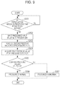
- FIG. 9 is a flowchart that illustrates one example of an abnormality assessment process of the fuel cell system according to a modification example 4 of the second embodiment of the present disclosure.
- FIG. 10 is a flowchart that illustrates one example of an abnormality assessment process of the fuel cell system according to a modification example 5 of the second embodiment of the present disclosure
- FIG. 11 is a diagram that schematically illustrates one example of a configuration of principal components of a fuel cell system according to a modification example 6 of the second embodiment of the present disclosure.
- FIG. 12 is a flowchart that illustrates one example of an abnormality assessment process of the fuel cell system according to a modification example 6 of the second embodiment of the present disclosure.
- the present inventors have conducted intensive studies about abnormality detection in a pressurizer in a fuel cell system that includes a recycling path, pressurizes anode off-gas by a pressurizer, and circulates and supplies the anode off-gas to an anode of a fuel cell via the recycling path.
- related art has the following problems.
- Japanese Unexamined Patent Application Publication No. 2005-32652 an assessment method about abnormalities of a pressurizer indicated by the above-described (a) to (c) has been suggested.
- Japanese Unexamined Patent Application Publication No. 2005-32652 does not take into consideration an operation condition of the fuel cell system in assessment of abnormality of the pressurizer and it is thus difficult to precisely assess abnormality of the pressurizer.
- abnormality of the pressurizer is assessed in an operation condition in which the composition of the anode off-gas in the recycling path is fixed and an assessment about whether or not abnormality of the pressurizer is present may thereby be performed more precisely.
- an assessment is made about abnormality of the pressurizer in an operation condition as either one of a timing in execution of a purge action, in which a fuel gas is supplied from a fuel gas supply path and the anode off-gas is discharged to the outside in a state where a first valve (purge valve) provided in an anode off-gas discharge path is opened, and a timing in prescribed time after the purge action and that assessment about abnormality of the pressurizer may thereby precisely be performed.
- a fuel cell system includes: a fuel cell that generates power by using a fuel gas and an oxidant gas; a fuel gas supply path that supplies the fuel gas to an anode entrance of the fuel cell; a recycling path that returns anode off-gas which is discharged from an anode exit of the fuel cell to an entrance of the fuel cell; an anode off-gas discharge path that branches from the recycling path and discharges the anode off-gas to an outside; a first valve that is provided in the anode off-gas discharge path; a pressurizer that is provided in the recycling path and pressurizes the anode off-gas which flows through the recycling path; and a controller that controls the pressurizer to act in at least one of a timing in execution of a purge action in which the fuel gas is supplied from the fuel gas supply path and the anode off-gas is discharged to the outside in a state where the first valve is opened and a timing in prescribed time after the purge action and that assesses abnormality
- the controller performs the control so as to cause the pressurizer to act in at least one of a timing in execution of the purge action in which the fuel gas is supplied from the fuel gas supply path and the anode off-gas is discharged to the outside in a state where the first valve is opened and a timing in the prescribed time after the purge action and assesses abnormality based on the pressure of the recycling path or of the anode off-gas discharge path in the control or the action amount of the pressurizer.
- the magnitude of the pressure loss that occurs in the fuel cell depends on the composition of the fuel gas that flows through the fuel cell. Further, in a closed circuit operation in which the anode off-gas is repeatedly circulated in the fuel gas supply path in a state where the first valve is closed, nitrogen is gradually included in the anode off-gas, and the composition of the fuel gas thus changes.
- an abnormality assessment for the pressurizer is performed in the purge action in which the fuel gas is supplied from the fuel gas supply path and the anode off-gas is discharged to the outside in a state where the first valve is opened or in the prescribed time after the purge action.
- the abnormality assessment for the pressurizer may be performed while the composition of the fuel gas that flows through the fuel cell is fixed.
- At least one of the timing in execution of the purge action for discharging the anode off-gas to the outside and the timing in the prescribed time after the purge action may be either one of a timing in execution of the purge action for discharging the anode off-gas to the outside and a timing in the prescribed time after the purge action. Further, the timing may be both of a timing in execution of the purge action for discharging the anode off-gas to the outside and a timing in the prescribed time after the purge action.
- the prescribed time after the purge action is properly set as elapsed time after the purge action in which a fluctuation in the composition is small from the composition of the fuel gas in the recycling path or in the anode off-gas discharge path at the time when the purge action is finished and the precision of the abnormality assessment for the pressurizer becomes equivalent to the precision in the purge action.
- the output (action amount) of the pressurizer may be monitored.
- the output (action amount) with respect to a prescribed indicated value changes compared to a case where the pressurizer normally works.
- an assessment may be made about whether or not abnormality of the pressurizer is present from the change in the action amount of the pressurizer. For example, when the action amount of the pressurizer with respect to the prescribed indicated value is a first action amount threshold value or less or a second action amount threshold value or more, which is greater than the first action amount threshold value, an assessment is made that abnormality is present.
- the fuel cell system according to the first aspect of the present disclosure provides an effect of more precisely assessing abnormality of the pressurizer than related art.
- the controller may be configured to assess that abnormality is present when the pressure of the recycling path that is upstream of the pressurizer or the pressure of the anode off-gas discharge path is a first threshold value or more.
- the abnormality assessment for the pressurizer may be performed in accordance with whether or not the pressure of the recycling path or the pressure of the anode off-gas discharge path is the first threshold value or more, regardless of the time change in the gas composition.
- the first threshold value is a pressure value of the anode off-gas discharged from the fuel cell, which is obtained in consideration of the decrease in the pressure loss which occurs in the fuel cell when the flow amount of the anode off-gas which flows through the recycling path decreases compared to the flow amount in a normal operation state of the pressurizer.
- the first threshold value may be set as the pressure value of the anode off-gas when the fuel gas of a flow amount as a lower limit value of the flow amount of the fuel gas that may maintain power generation of the fuel cell is supplied to the fuel cell.
- the controller may be configured to assess that abnormality is present when the pressure of the recycling path that is upstream of the pressurizer or the pressure of the anode off-gas discharge path is a second threshold value or less.
- the abnormality assessment for the pressurizer may be performed in accordance with whether or not the pressure of the recycling path or the pressure of the anode off-gas discharge path is the second threshold value or less, regardless of the time change in the gas composition.
- an assessment may be made about whether or not the fuel cell system is in a state where an excess flow amount of the anode off-gas over an appropriate flow amount is supplied to the fuel gas.
- the second threshold value is a pressure value of the anode off-gas discharged from the fuel cell, which is obtained in consideration of the increase in the pressure loss which occurs in the fuel cell when the flow amount of the anode off-gas which flows through the recycling path increases compared to the flow amount in the normal operation state of the pressurizer.
- the second threshold value may be set as the pressure value of the anode off-gas when the fuel gas of a flow amount as an upper limit value of the flow amount of the fuel gas that may maintain power generation of the fuel cell is supplied to the fuel cell.
- the controller may be configured to assess the abnormality at a start of the fuel cell.
- the controller performs an assessment of abnormality at a start of the fuel cell and may thus perform the abnormality assessment for the pressurizer before power generation of the fuel cell is started.
- the fuel cell system according to a fifth aspect of the present disclosure may be configured to further include a second valve that is provided in the fuel gas supply path, and the controller may be configured to perform control to close the second valve and to stop supply of the fuel gas from the fuel gas supply path when an assessment is made that the abnormality is present.
- the controller may perform control to close the second valve and to stop the supply of the fuel gas from the fuel gas supply path.
- the fuel cell system may be inhibited from being operated in a state where abnormality occurs to the pressurizer.
- the fuel cell system according a sixth aspect of the present disclosure may be configured to further include an output device that outputs information which indicates the abnormality when the controller assesses that the abnormality is present.
- the output device may output the information that indicates abnormality of the pressurizer and may thus notify that a cause of stop of the operation of the fuel cell system is the pressurizer.
- examples of the output device include a display, a printer, a sound output device, and a light emitting unit. Particularly when the output device is a display, the display may visually notify that a cause of stop of the operation of the fuel cell system is the pressurizer.
- FIG. 1 is a diagram that schematically illustrates one example of a configuration of principal components of the fuel cell system 50 according to the first embodiment of the present disclosure.
- the fuel cell system 50 includes a fuel cell 1 , a fuel gas supply path 2 , an oxidant gas supply path 3 , a controller 4 , an anode off-gas discharge path 5 , a cathode off-gas discharge path 6 , a recycling path 7 , a pressurizer 10 , and a purge valve (first valve) 11 .
- the fuel cell 1 is a power generation device that generates power by an electrochemical reaction between fuel gas supplied to an anode and oxidant gas supplied to a cathode. That is, the fuel cell 1 has a laminated body of a membrane electrode assembly (MEA) (not illustrated), and the MEA is configured with an electrolyte (not illustrated) that uses a polymer electrolyte membrane and an anode and a cathode that are arranged to interpose the electrolyte membrane between those.
- MEA membrane electrode assembly
- Each of the anode and the cathode is configured with a catalyst layer formed of carbon particles that support a noble metal catalyst such as platinum and a gas diffusion layer formed of carbon paper or carbon felt.
- the MEA is interposed between a pair of separators, a fuel gas flow path is provided between one separator and the anode, and an oxidant gas flow path is provided between the other separator and the cathode.
- the fuel gas is supplied to the fuel gas flow path via the fuel gas supply path 2
- the oxidant gas is supplied to the oxidant gas flow path via the oxidant gas supply path 3 . Accordingly, an electrochemical reaction occurs between the fuel gas and the oxidant gas, and power generation is thereby performed.
- the fuel gas supply path 2 is connected with an anode entrance of the fuel cell 1 , and the fuel gas is supplied to the fuel gas flow path of the fuel cell 1 via the fuel gas supply path 2 .
- the oxidant gas supply path 3 is connected with a cathode entrance of the fuel cell 1 , and air as the oxidant gas is supplied to the oxidant gas flow path of the fuel cell 1 via the oxidant gas supply path 3 .
- the recycling path 7 is connected with an anode exit of the fuel cell 1 , and the anode off-gas discharged from the anode of the fuel cell 1 may be returned to the anode entrance of the fuel cell 1 via the recycling path 7 .
- the anode off-gas discharge path 5 which branches from the recycling path 7 is provided, and a configuration is made such that the anode off-gas discharged from the anode of the fuel cell 1 may be discharged to the outside of the fuel cell system 50 via the anode off-gas discharge path 5 .
- the cathode off-gas discharge path 6 is connected with a cathode exit of the fuel cell 1 , and cathode off-gas discharged from the cathode of the fuel cell 1 is discharged to the outside of the fuel cell system 50 via the cathode off-gas discharge path 6 .
- an end portion on the side connected with the fuel gas supply path 2 will be referred to as anode entrance
- an end portion on the side connected with the recycling path 7 will be referred to as anode exit.
- an end portion on the side connected with the oxidant gas supply path 3 will be referred to as cathode entrance
- an end portion on the side connected with the cathode off-gas discharge path 6 will be referred to as cathode exit.
- the fuel gas supply path 2 is connected with a fuel gas supply source (not illustrated), and the other end portion of the fuel gas supply path 2 is connected with the anode entrance of the fuel cell 1 .
- the fuel gas is supplied from the fuel gas supply source via the fuel gas supply path 2 and the fuel gas flow path to the anode.
- the fuel gas is hydrogen or gas that contains hydrogen, and reformed gas obtained through a reforming reaction of source gas such as city gas by a reformer and hydrogen obtained by water electrolysis or the like may be used, for example.
- Piping of a flame-retardant material is in general used for the fuel gas supply path 2 because the fuel gas that flows on the inside is flammable gas. Note that the flow amount of the fuel gas supplied from the fuel gas supply path 2 is adjusted in accordance with the power generation amount of the fuel cell 1 . Further, a humidifier for humidifying the fuel gas may be provided in the fuel gas supply path 2 .
- the pressure of the fuel gas supplied from the fuel gas supply source via the fuel gas supply path 2 is set to become regular based on the pressure loss of the fuel gas that flows through the fuel gas flow path of the fuel cell 1 .
- a primary pressure of the fuel gas supplied from the reformer via the fuel gas supply path 2 to the fuel cell 1 may become lower than the pressure loss of the fuel gas that flows through the fuel gas flow path because the pressure of the source gas supplied from a source gas supply source (not illustrated) to the reformer is low.
- a configuration is possible in which a pressurizer is provided in the fuel gas supply path 2 and the fuel gas is pressurized by the pressurizer and then supplied to the fuel gas flow path.
- the primary pressure of the fuel gas supplied from the fuel gas supply source via the fuel gas supply path 2 to the fuel cell 1 may become higher than the pressure loss of the fuel gas that flows through the fuel gas flow path.
- a pressure adjuster (not illustrated) is provided in the fuel gas supply path 2 , the pressure is adjusted to a prescribed pressure that is higher than the pressure loss, and the fuel gas is thereby supplied to the fuel cell 1 via the fuel gas supply path 2 .
- the pressure of the fuel gas supplied to the fuel cell 1 via the fuel gas supply path 2 is set to become regular based on the pressure loss of the fuel gas that flows through the fuel gas flow path of the fuel cell 1 .
- the pressure adjuster is a device that adjusts the pressure of the fuel gas which flows through the fuel gas supply path 2 and includes a driven type pressure adjusting valve and a regulator that make the pressure variable and a governor that adjusts the pressure to a regular value, for example. Accordingly, the pressure of the fuel gas supplied from the fuel gas supply source via the fuel gas supply path 2 to the fuel cell 1 is maintained regular.
- An end portion of the oxidant gas supply path 3 is connected with the oxidant gas flow path of the fuel cell 1 .
- the oxidant gas is supplied from an oxidant gas supplier 8 via the oxidant gas supply path 3 and the oxidant gas flow path to the cathode.
- air may be used for the oxidant gas.
- the oxidant gas supplier 8 may be configured with a compressor, an electromagnetic induction type diaphragm pump, and so forth, for example. Accordingly, the oxidant gas may be pressurized by the oxidant gas supplier 8 and supplied to the oxidant gas flow path of the fuel cell 1 .
- a humidifier (not illustrated) for humidifying the oxidant gas may be provided in the oxidant gas supply path 3 .
- the fuel cell system 50 in order to reuse the anode off-gas as the fuel gas, includes the recycling path 7 whose one end portion is connected with the anode exit and whose other end portion is connected with the fuel gas supply path 2 . Further, the fuel cell system 50 is configured such that the anode off-gas discharged from the fuel cell 1 is returned to the anode entrance via the recycling path 7 .
- the fuel gas supplied to the anode of the fuel cell 1 includes the fuel gas that is supplied from the fuel gas supply source and the anode off-gas that is supplied via the recycling path 7 .
- One end portion of the recycling path 7 is connected with the anode exit of the fuel cell 1 , and the other end portion of the recycling path 7 is connected with the fuel gas supply path 2 , for example.
- a circulation path that circulates the anode off-gas is configured with the fuel gas supply path 2 with respect to the flow of the fuel gas, the fuel gas flow path of the fuel cell 1 , and the recycling path 7 .
- the fuel cell system 50 may cause the anode off-gas discharged from the anode exit to merge with the fuel gas that flows through the fuel gas supply path 2 and may again supply the anode off-gas and the fuel gas to the anode entrance of the fuel cell 1 .
- Piping of a flame-retardant material is preferably used for the recycling path 7 because the anode off-gas that flows on the inside is flammable gas. Further, the pressurizer 10 is provided in the recycling path 7 .
- the pressurizer 10 is a pressurizing pump that raises the pressure of the anode off-gas which flows through the recycling path 7 and controls the flow amount of the anode off-gas caused to merge into the fuel gas supply path 2 in order to again supply the anode off-gas discharged from the anode exit to the anode entrance.
- an electromagnetic induction type diaphragm pump which may adjust the flow amount of the anode off-gas by an input voltage may be used.
- the pressurizer 10 may be a turbo type (non-positive displacement type) pump that adjusts the flow amount of the anode off-gas by rotating an impeller.
- the pressure of the anode off-gas that flows through the recycling path 7 by the pressure loss caused when the fuel gas flows through the fuel gas flow path of the fuel cell 1 becomes lower than the pressure of the fuel gas that flows through the fuel gas supply path 2 .
- the pressurizer 10 placed in the recycling path 7 is used to raise the pressure of the anode off-gas that flows through the recycling path 7 , and the anode off-gas is thereby caused to flow into the fuel gas supply path 2 .
- the anode off-gas discharge path 5 branches in a position on an upstream side of the pressurizer 10 with respect to the flow of recycle gas in the recycling path 7 and extends to the outside of the fuel cell system 50 .
- Piping of a flame-retardant material is preferably used for the anode off-gas discharge path 5 because the anode off-gas that flows on the inside is flammable gas.
- a purge valve 11 that adjusts the flow path of the anode off-gas discharge path 5 is provided in the anode off-gas discharge path 5 .
- the purge valve 11 for example, a solenoid valve may be used.
- the purge valve 11 is not particularly limited. Further, the purge valve 11 may be a control valve or an on-off valve. When the purge valve 11 is opened and becomes an open state, the anode off-gas that flows through the recycling path 7 is discharged to the outside via the anode off-gas discharge path 5 by passing through the purge valve 11 .
- the cathode off-gas discharge path 6 is connected with the cathode exit of the fuel cell 1 and discharges the cathode off-gas discharged from the oxidant gas flow path to the outside.
- the cathode off-gas includes water.
- the cathode off-gas also includes this water.
- piping which is not likely to be corroded by water for example, stainless steel piping and resin piping of cross-linked polyethylene is used.
- the controller 4 performs various kinds of control of the units included in the fuel cell system 50 and includes an arithmetic unit such as a CPU (not illustrated), a storage unit such as a ROM or a RAM (not illustrated).
- the storage unit stores a basic program of the fuel cell system 50 and information such as various kinds of fixed data, for example.
- the arithmetic unit reads out and executes the basic program and so forth, and the controller 4 thereby controls actions of the units.
- the controller 4 may be configured with a single controller 4 that performs centralized control or may be configured with plural controllers 4 that mutually and cooperatively perform distributed control.
- the controller 4 controls the pressurizer 10 to act in at least one of a timing in execution of a purge action in which the fuel gas is supplied from the fuel gas supply path 2 and the anode off-gas is discharged to the outside in a state where the purge valve 11 is opened and a timing in prescribed time after the purge action.
- the controller 4 is configured to assess abnormality of the pressurizer 10 based on the pressure of the anode off-gas that flows through the recycling path 7 or the anode off-gas discharge path 5 or the action amount of the pressurizer 10 while such control is executed.
- the pressurizer 10 is a rotary pump
- the rotational speed of the pump corresponds to the action amount.
- the action amount is not limited to this example.
- the controller 4 assesses abnormality of the pressurizer 10 in either one of a timing in execution of the purge action for discharging the anode off-gas to the outside and a timing in the prescribed time after the purge action or both of a timing in execution of the purge action for discharging the anode off-gas to the outside and a timing in the prescribed time after the purge action.
- the controller 4 assesses abnormality of the pressurizer 10 based on the pressure of the anode off-gas that flows through the recycling path 7 or the anode off-gas discharge path 5 . That is, when the output of the pressurizer 10 lowers due to failure, the flow amount of the anode off-gas that flows through the recycling path 7 lowers. Thus, if the pressure of the fuel gas supplied to the fuel cell 1 through the fuel gas supply path 2 is regular, the pressure loss in the fuel cell 1 lowers, and the pressure of the anode off-gas discharged from the anode exit of the fuel cell 1 becomes high compared to a case where the pressurizer 10 normally works. Thus, an assessment may be made about whether or not abnormality of the pressurizer 10 is present from the pressure of the anode off-gas that flows through the recycling path 7 or the anode off-gas discharge path 5 .
- the controller 4 may be configured to obtain the value of the pressure of the anode off-gas based on a detection result by a pressure detector that measures the pressure of the anode off-gas which flows through the recycling path 7 or the anode off-gas discharge path 5 .
- the controller 4 may be configured to obtain the value of the pressure of the anode off-gas based on a detection result by a detector that detects any physical quantity which correlates with the pressure of the anode off-gas.
- the controller 4 assesses that abnormality is present when the pressure of the recycling path 7 that is upstream of the pressurizer 10 or the pressure of the anode off-gas discharge path 5 is a first threshold value or more.
- the first threshold value is a pressure value of the anode off-gas discharged from the fuel cell 1 , which is obtained in consideration of the decrease in the pressure loss which occurs in the fuel cell 1 when the flow amount of the anode off-gas which flows through the recycling path 7 decreases compared to the flow amount in a normal operation state of the pressurizer 10 .
- the first threshold value may be set as the pressure value of the anode off-gas when the fuel gas of a flow amount as a lower limit value of the flow amount of the fuel gas that may maintain power generation of the fuel cell 1 is supplied to the fuel cell 1 .
- the controller 4 assesses that abnormality is present when the pressure of the recycling path 7 that is upstream of the pressurizer 10 or the pressure of the anode off-gas discharge path 5 is a second threshold value or less.
- the second threshold value is a pressure value of the anode off-gas discharged from the fuel cell 1 , which is obtained in consideration of the increase in the pressure loss which occurs in the fuel cell 1 when the flow amount of the anode off-gas which flows through the recycling path 7 increases compared to the flow amount in the normal operation state of the pressurizer 10 .
- the second threshold value may be set as the pressure value of the anode off-gas when the fuel gas of a flow amount as an upper limit value of the flow amount of the fuel gas that may maintain power generation of the fuel cell 1 is supplied to the fuel cell 1 .
- the controller 4 may assess abnormality of the pressurizer 10 based on the action amount of the pressurizer 10 .
- the controller 4 monitors the output (action amount) of the pressurizer 10 . Then, the controller 4 assesses whether or not abnormality of the pressurizer 10 is present from the change in the action amount of the pressurizer 10 with respect to the prescribed indicated value.
- the action amount of the pressurizer 10 with respect to the prescribed indicated value is a first action amount threshold value or less or a second action amount threshold value or more, which is greater than the first action amount threshold value
- an assessment may be made that the pressurizer 10 is abnormal.
- controller 4 may be configured to recognize the change in the action amount of the pressurizer 10 based on a detection result of a detector that detects the change amount in the action amount of the pressurizer 10 , for example.
- FIG. 2 is a diagram that schematically illustrates one example of a configuration of principal components of the fuel cell system 100 according to the second embodiment of the present disclosure.
- the fuel cell system 100 according to the second embodiment further includes the oxidant gas supplier 8 , a pressure detector 12 , and a fuel gas supply valve (second valve) 13 .
- the fuel cell system 100 is configured to include the oxidant gas supplier 8 as one example of a device that supplies the oxidant gas to the fuel cell 1 , the pressure detector 12 as one example of a device that detects the pressure of the anode off-gas, and the fuel gas supply valve 13 as one example of a device that controls the supply amount of the fuel gas.
- a merging unit 9 is provided as a connection point between the fuel gas supply path 2 and the recycling path 7 . One end portion of the recycling path 7 is connected with the anode exit of the fuel cell 1 , and the other end portion of the recycling path 7 is connected with the merging unit 9 of the fuel gas supply path 2 .
- a circulation path that circulates the anode off-gas is configured with a portion of the fuel gas supply path 2 on a downstream side of the merging unit 9 with respect to the flow of the fuel gas, the fuel gas flow path of the fuel cell 1 , and the recycling path 7 .
- the fuel cell system 100 according to the second embodiment has a similar configuration to the fuel cell system 50 according to the first embodiment except for a point that the fuel cell system 100 further includes the above members. Thus, the same reference numerals are provided to similar members, and descriptions thereof will not be made.
- the fuel gas supply valve 13 is provided to the portion in the fuel gas supply path 2 , which is upstream of the merging unit 9 with respect to the flow of the fuel gas.
- the fuel gas supply valve 13 is a regulator valve that makes the fuel gas supply path 2 an open state to supply the fuel gas to the anode of the fuel cell 1 and makes the fuel gas supply path 2 a closed state to block supply of the fuel gas to the anode of the fuel cell 1 . It is sufficient that the fuel gas supply valve 13 may adjust the flow amount of the fuel gas. For example, a solenoid valve may be raised as an example.
- the pressure detector 12 is provided to a portion between the anode exit of the fuel cell 1 and the pressurizer 10 in the recycling path 7 or a portion between the anode exit and the purge valve 11 .
- the portion between the anode exit and the purge valve 11 is a section in which a portion of the recycling path 7 from a connection point with the anode exit to a connection point with the anode off-gas discharge path 5 is combined with a portion of the anode off-gas discharge path 5 from a connection point with the recycling path 7 to the purge valve 11 .
- the pressure detector 12 may be any unit that may measure the pressure of the anode off-gas which flows through the anode off-gas discharge path 5 and is not particularly limited.
- the pressure detector 12 may be a diaphragm type pressure sensor that measures a gauge pressure, for example.
- FIG. 3 is a flowchart that illustrates one example of the abnormality assessment process of the fuel cell system 100 according to the second embodiment of the present disclosure.
- FIG. 4 is a graph that represents one example of the relationship between an input value Vc and a second pressure value P 2 (first threshold value) in the fuel cell system 100 according to the second embodiment of the present disclosure.
- Vc an input value
- P 2 first threshold value
- the vertical axis represents the pressure
- the horizontal axis represents the input voltage as the input value Vc
- the broken line represents the relationship between the input value Vc and the pressure value in a normal operation of the fuel cell system 100
- the solid line represents the relationship between the input value Vc and the second pressure value P 2 .
- the abnormality assessment process for the pressurizer 10 is conducted in a timing in execution of the purge action in which the fuel gas is supplied from the fuel gas supply path 2 to the fuel cell 1 and the anode off-gas discharged from the fuel cell 1 is discharged to the outside in a state where the purge valve 11 is opened or a timing in prescribed time after the purge action or both of a timing in execution of the purge action and a timing in the prescribed time after the purge action.
- the second pressure value P 2 is the pressure value that corresponds to a lower limit value of the fuel gas flow amount at which the fuel cell 1 may maintain power generation.
- the second pressure value P 2 is the pressure value of the anode off-gas when the fuel gas of a flow amount as the lower limit value of the flow amount of the fuel gas that may maintain power generation of the fuel cell 1 is supplied to the fuel cell 1 , the pressure value being set corresponding to the input value Vc.
- the second pressure value P 2 is a pressure value, which is obtained in consideration of the decrease in the pressure loss which occurs in the fuel cell 1 when the flow amount of the anode off-gas which flows through the recycling path 7 decreases compared to the flow amount in the normal operation state.
- the lower limit value of the fuel gas flow amount at which the fuel cell 1 may maintain power generation may be considered to be a lower limit value in the range of the flow amount of the fuel gas, which is requested for obtainment of a power generation amount set in the fuel cell 1 , and may be considered to be the flow amount from which a prescribed power generation amount may not be obtained if the flow amount of the fuel gas is below the lower limit value.
- the flow amount of the anode off-gas supplied to the merging unit 9 lowers because some sort of abnormality occurs to the pressurizer 10 , the flow amount of the fuel gas supplied to the anode entrance of the fuel cell 1 also lowers. Thus, the pressure loss that occurs in the fuel cell 1 also becomes small.
- the fuel cell system 100 according to the second embodiment is set such that the pressure of the fuel gas supplied to the fuel cell 1 via the fuel gas supply path 2 becomes regular, the relationship is present in which the pressure of the anode off-gas discharged from the fuel cell 1 becomes higher than the normal operation state of the fuel cell system 100 .
- the flow amount of the fuel gas supplied to the anode of the fuel cell 1 may be recognized based on the pressure detected by the pressure detector 12 .
- the fuel cell system 100 sets the second pressure value P 2 as the pressure value that corresponds to the lower limit value of the fuel gas flow amount at which the fuel cell 1 may maintain power generation and in advance stores, in a storage unit, a graph which represents the correspondence relationship between the second pressure value P 2 and the input value Vc (input voltage) input to the pressurizer 10 .
- the controller 4 inputs a prescribed input value Vc to the pressurizer 10 (step S 101 ).
- a certain voltage value as the input value Vc is input to the pressurizer 10 .
- the input value Vc is not limited to this, but a configuration is possible in which a pulse which indicates a voltage value is input as the input value Vc.
- the controller 4 reads out the second pressure value P 2 that corresponds to the input value Vc from the storage unit (step S 102 ). That is, as illustrated in FIG. 4 , the storage unit in advance stores information that indicates the relationship between the input value Vc and the second pressure value P 2 . Accordingly, the controller 4 reads out the second pressure value P 2 that corresponds to the prescribed input value Vc based on the stored information.
- the controller 4 acquires a first pressure value P 1 detected by the pressure detector 12 (step S 103 ), measures the difference between the first pressure value P 1 and the second pressure value P 2 , and assesses whether or not the difference is less than zero (step S 104 ).
- the controller 4 determines that the flow amount of the anode off-gas supplied by the pressurizer 10 is not insufficient and the pressurizer 10 is normal (step S 105 ).
- step S 104 the controller 4 determines that the flow amount of the anode off-gas supplied by the pressurizer 10 is insufficient and abnormality occurs to the pressurizer 10 (step S 106 ).
- the controller 4 inputs a prescribed input value Vc to the pressurizer 10 , compares the first pressure value P 1 detected by the pressure detector 12 with the second pressure value P 2 stored in advance, and may thereby assess whether or not abnormality occurs to the pressurizer 10 and the flow amount of the anode off-gas that merges with the fuel gas in the fuel gas supply path 2 through the recycling path 7 is insufficient.
- the controller 4 may determine whether or not the operation of the fuel cell system 100 according to the second embodiment may be continued.
- FIG. 5 is a flowchart that illustrates one example of an abnormality assessment process of the fuel cell system 100 according to the modification example 1 of the second embodiment of the present disclosure.
- the abnormality assessment process for the pressurizer 10 is conducted in a timing in execution of the purge action or a timing in prescribed time after the purge action or both of a timing in execution of the purge action and a timing in the prescribed time after the purge action.
- the fuel cell system 100 according to the modification example 1 of the second embodiment a description will be made by raising a case where each of the fuel gas supply valve 13 and the purge valve 11 is in an opened state and the abnormality assessment process for the pressurizer 10 is performed in execution of the purge action as an example.
- the fuel cell system 100 according to the modification example 1 of the second embodiment performs the abnormality assessment process for the pressurizer 10 similarly to the fuel cell system 100 according to the second embodiment except for a point that the timing for performing the abnormality assessment process is limited.
- the controller 4 first makes the fuel gas supply valve 13 and the purge valve 11 the open state (step S 201 ). In a timing when the fuel gas supply valve 13 and the purge valve 11 are in the open state as described above, the controller 4 inputs a prescribed input value Vc to the pressurizer 10 (step S 202 ). A subsequent process to this (a process of step S 203 to step S 207 ) is similar to the process of step S 102 to step S 106 of the abnormality assessment process illustrated in FIG. 3 , and a description will thus not be made.
- the magnitude of the pressure loss that occurs in the fuel cell 1 depends on the composition of the fuel gas that flows through the fuel cell 1 . Further, in a closed circuit operation in which the anode off-gas is repeatedly circulated in the fuel gas supply path 2 in a state where the purge valve 11 is closed, nitrogen is gradually included in the anode off-gas, and the composition of the fuel gas thus changes.
- the controller 4 performs the abnormality assessment process for the pressurizer 10 while the fuel gas supply valve 13 and the purge valve 11 are made the open state.
- the abnormality assessment process for the pressurizer 10 when the abnormality assessment process for the pressurizer 10 is performed, nitrogen and so forth that are produced in power generation of the fuel cell 1 may be discharged to the outside through the purge valve 11 . Therefore, an abnormality assessment for the pressurizer 10 may be performed while the fuel gas that flows through the fuel gas flow path in the fuel cell 1 is made gas with fixed composition.
- the relationship between a prescribed input value Vc and the second pressure value P 2 may be obtained regardless of the time change in the composition of the fuel gas.
- the relation formula between the input value Vc and the second pressure value P 2 may be simplified, errors in the relationship between the input value Vc and the second pressure value P 2 due to the difference in the gas composition may be lessened, and the abnormality assessment for the pressurizer 10 may thereby be performed precisely.
- the fuel cell system 100 according to a modification example 2 of the second embodiment is different compared to the fuel cell system 100 according to the second embodiment in a point that the storage unit in advance stores a graph that represents the correspondence relationship between each of the second pressure value P 2 and a third pressure value P 3 (second threshold value) and the input value Vc (input voltage) input to the pressurizer 10 . That is, the fuel cell system 100 according to the modification example 2 sets the second pressure value P 2 as the pressure value that corresponds to a lower limit value of the fuel gas which is requested for maintenance of power generation of the fuel cell 1 and sets the third pressure value P 3 as a pressure value that corresponds to an upper limit value. Further, the storage unit in advance stores the graph that represents the correspondence relationship between each of the second pressure value P 2 and the third pressure value P 3 and the input value Vc (input voltage) input to the pressurizer 10 .
- the third pressure value P 3 is the pressure value that corresponds to an upper limit value of the fuel gas flow amount at which the fuel cell 1 may maintain power generation.
- the third pressure value P 3 is the pressure value of the anode off-gas when the fuel gas of a flow amount as the upper limit value of the flow amount of the fuel gas that may maintain power generation of the fuel cell 1 is supplied to the fuel cell 1 , the pressure value being set corresponding to the input value Vc.
- the third pressure value P 3 is a pressure value, which is obtained in consideration of the increase in the pressure loss which occurs in the fuel cell 1 when the flow amount of the anode off-gas which flows through the recycling path 7 increases compared to the flow amount in the normal operation state.
- the configuration of the fuel cell system 100 according to the modification example 2 is similar to the configuration of the fuel cell system 100 according to the second embodiment except for a point that the storage unit in advance stores the graph that represents the correspondence relationship between each of the second pressure value P 2 and the third pressure value P 3 and the input value Vc.
- the storage unit in advance stores the graph that represents the correspondence relationship between each of the second pressure value P 2 and the third pressure value P 3 and the input value Vc.
- FIG. 6 is a flowchart that illustrates one example of an abnormality assessment process of the fuel cell system 100 according to the modification example 2 of the second embodiment of the present disclosure.
- FIG. 7 is a graph that represents one example of the relationship among the input value Vc, the second pressure value P 2 , and the third pressure value P 3 in the fuel cell system 100 according to the modification example 2 of the second embodiment of the present disclosure.
- Vc the input value
- P 2 the second pressure value
- P 3 third pressure value
- the vertical axis represents the pressure
- the horizontal axis represents the input voltage
- the broken line with shorter line segments represents the relationship between the input value Vc and the pressure value in the normal operation of the fuel cell system 100
- the solid line represents the relationship between the input value Vc and the second pressure value P 2
- the broken line with longer line segments represents the relationship between the input value Vc and the third pressure value P 3 .
- the second pressure value P 2 is the pressure value that corresponds to the lower limit value of the fuel gas flow amount at which the fuel cell 1 may maintain power generation.
- the third pressure value P 3 is the pressure value that corresponds to the upper limit value of the fuel gas flow amount at which the fuel cell 1 may maintain power generation.
- the upper limit value of the fuel gas flow amount at which the fuel cell 1 may maintain power generation may be considered to be an upper limit value in the range of the flow amount of the fuel gas, which is requested for obtainment of a power generation amount set in the fuel cell 1 .
- the flow amount that exceeds the upper limit value may be considered to be an excess flow amount.
- a process of step S 301 to step S 303 of the abnormality assessment process for the pressurizer 10 is similar to the process of step S 101 to step S 103 of the abnormality assessment process for the pressurizer 10 , which is conducted in the fuel cell system 100 according to the second embodiment.
- a description thereof will not be made, and a description will be made about a process of step S 304 and subsequent steps.
- the abnormality assessment process for the pressurizer 10 in the fuel cell system 100 according to the modification example 2 of the second embodiment is conducted, similarly to the fuel cell system 100 according to the second embodiment, in a timing in execution of the purge action or a timing in prescribed time after the purge action or both of a timing in execution of the purge action and a timing in the prescribed time after the purge action.
- step S 304 the controller 4 measures the difference between the first pressure value P 1 and the second pressure value P 2 and assesses whether or not the difference is less than zero (step S 304 ).
- the controller 4 determines that the flow amount of the anode off-gas supplied by the pressurizer 10 is insufficient and abnormality occurs to the pressurizer 10 (step S 306 ).
- the controller 4 determines that the flow amount of the anode off-gas supplied by the pressurizer 10 is not insufficient.
- the controller 4 reads out a third pressure value P 3 that corresponds to the prescribed input value Vc from the storage unit (step S 305 ). That is, as illustrated in FIG. 7 , the storage unit in advance stores information that indicates the relationship between the input value Vc and the second pressure value P 2 and the relationship between the input value Vc and the third pressure value P 3 . Accordingly, the controller 4 reads out the third pressure value P 3 that corresponds to the prescribed input value Vc based on the stored information.
- the controller 4 measures the difference between the first pressure value P 1 detected by the pressure detector 12 and the third pressure value P 3 and assesses whether or not the difference is greater than zero (step S 307 ).
- the controller 4 determines that P 1 ⁇ P 3 >0 (“Yes” in step S 307 )
- the controller 4 determines that the anode off-gas is not excessively supplied by the pressurizer 10 compared to the flow amount that is requested for power generation and the pressurizer 10 is normal (step S 308 ).
- step S 307 when the controller 4 determines that P 1 ⁇ P 3 ⁇ 0 (“No” in step S 307 ), the controller 4 determines that the anode off-gas is excessively supplied by the pressurizer 10 compared to the flow amount that is requested for power generation and the pressurizer 10 is abnormal (step S 306 ).
- the controller 4 inputs a prescribed input value Vc to the pressurizer 10 , compares the first pressure value P 1 detected by the pressure detector 12 with the second pressure value P 2 and the third pressure value P 3 , and may thereby assess whether or not abnormality occurs to the pressurizer 10 and the flow amount of the anode off-gas supplied through the recycling path 7 is insufficient or whether or not the flow amount is excess.
- the controller 4 may determine whether or not the operation of the fuel cell system 100 according to the modification example 2 of the second embodiment may be continued.
- FIG. 8 is a flowchart that illustrates one example of an abnormality assessment process of the fuel cell system 100 according to the modification example 3 of the second embodiment of the present disclosure.
- the fuel cell system 100 according to the modification example 3 of the second embodiment is different compared to the fuel cell system 100 according to the second embodiment in a point that the fuel cell system 100 performs the abnormality assessment process for the pressurizer 10 in a timing in execution of the purge action in a standby state of the fuel cell system 100 or a timing in prescribed time after the purge action or both of a timing in execution of the purge action and a timing in the prescribed time after the purge action but performs a similar process to the fuel cell system 100 according to the second embodiment except for a point that timing for performing the abnormality assessment process is limited.
- the controller 4 first assesses whether or not the fuel cell system 100 is in the standby state (either one of a timing in execution of the purge action or a timing in the prescribed time after the purge action) (step S 401 ).
- the controller 4 assesses that the fuel cell system 100 is in the standby state (“Yes” in step S 401 )
- the controller 4 inputs a prescribed input value Vc to the pressurizer 10 (step S 402 ).
- the controller 4 repeats the assessment in step S 401 again.
- the standby state of the fuel cell system 100 is a state where the temperature of the fuel cell 1 does not reach the temperature for power generation (steady operation) and the fuel cell 1 does not supply power to an external load.
- a state of the fuel cell system 100 at a start may be raised as an example.
- the start mentioned here is a period after a stop command is input to the fuel cell system until a start command is input or a period after the stop command is input until the start command is input and the temperature of the fuel cell (the temperature of a stack of the fuel cell) rises to a prescribed temperature in power generation (steady operation) and is a state where power is not supplied to the external load.
- the prescribed temperature in power generation (steady operation) is preset in accordance with the configuration of the stack of the fuel cell.
- a subsequent process to this (a process of step S 402 to step S 407 ) is similar to the process of step S 101 to step S 106 of the abnormality assessment process illustrated in FIG. 3 , and a description will thus not be made.
- the fuel cell system 100 may assess whether or not the pressurizer 10 is abnormal before power generation of the fuel cell 1 .
- failure of the fuel cell system 100 due to abnormality of the pressurizer 10 may be avoided before power generation is performed.
- FIG. 9 is a flowchart that illustrates one example of an abnormality assessment process of the fuel cell system 100 according to the modification example 4 of the second embodiment of the present disclosure.
- the fuel cell system 100 according to the modification example 4 of the second embodiment is different compared to the fuel cell system 100 according to the second embodiment in a point that the fuel cell system 100 performs the abnormality assessment process for the pressurizer 10 in a timing in execution of the purge action by discharging the anode off-gas that flows through the recycling path 7 in the operation of the fuel cell system 100 or a timing in prescribed time after the purge action or both of a timing in execution of the purge action and a timing in the prescribed time after the purge action.
- the fuel cell system 100 according to the modification example 4 performs a similar process to the fuel cell system 100 according to the second embodiment except for a point that the timing for performing the abnormality assessment process is limited.
- the controller 4 first assesses whether or not the timing is a timing in execution of the purge action by discharging the anode off-gas that flows through the recycling path 7 in the operation of the fuel cell system 100 and/or a timing in the prescribed time after the purge action (step S 501 ).
- the controller 4 inputs a prescribed input value Vc to the pressurizer 10 (step S 502 ).
- step S 501 when the controller 4 assesses that the timing is not a timing in execution of the purge action in the fuel cell system 100 and/or a timing in the prescribed time after the purge action (“No” in step S 501 ), the controller 4 repeats the assessment in step S 501 again.
- a subsequent process to this (a process of step S 503 to step S 507 ) is similar to the process of step S 102 to step S 106 of the abnormality assessment process illustrated in FIG. 3 , and a description will thus not be made.
- the fuel gas in measurement of the first pressure value P 1 may be made single composition (hydrogen) even while the fuel cell system 100 is acting.
- the relationship between a prescribed input value Vc and the second pressure value P 2 may be obtained regardless of the time change in the composition of the anode off-gas.
- the relation formula between the input value Vc and the second pressure value P 2 may be simplified, errors in the relationship between the input value Vc and the second pressure value P 2 due to the difference in the gas composition may be lessened, and the abnormality assessment for the pressurizer 10 may thereby be performed precisely.
- a timing in the prescribed time after the purge action is a period after the purge action and before the next purge action is started, for example, and is a timing within a period in which the precision of the abnormality assessment for the pressurizer 10 is equivalent to a timing in the purge action (for example, within a period in which the hydrogen concentration in the anode off-gas does not become less than 95%).
- a configuration of the fuel cell system 100 according to a modification example 5 according to the second embodiment is a similar configuration to the fuel cell system 100 according to the second embodiment. Thus, a description about a device configuration will not be made.
- FIG. 10 is a flowchart that illustrates one example of an abnormality assessment process of the fuel cell system 100 according to the modification example 5 of the second embodiment of the present disclosure.
- the fuel cell system 100 according to the modification example 5 of the second embodiment is different compared to the fuel cell system 100 according to the second embodiment in a point that when the controller 4 assesses that the pressurizer 10 is abnormal, the supply of the fuel gas is stopped by making the fuel gas supply valve a closed state.
- the fuel cell system 100 according to the modification example 5 performs a similar process to the fuel cell system 100 according to the second embodiment.
- step S 701 to step S 706 of the abnormality assessment process illustrated in FIG. 10 is similar to the process of step S 101 to step S 106 of the abnormality assessment process illustrated in FIG. 3 , and a description will thus not be made.
- the controller 4 performs control so as to make the fuel gas supply valve 13 the closed state and to stop the supply of the fuel gas from the fuel gas supply path 2 to the fuel cell 1 (step S 707 ).
- the fuel gas supply valve 13 is made the closed state, the fuel gas is thereby not supplied to the fuel cell 1 , and the fuel cell system 100 may thus be stopped safely.
- FIG. 11 is a diagram that schematically illustrates one example of a configuration of principal components of the fuel cell system 100 according to the modification example 6 of the second embodiment of the present disclosure.
- the fuel cell system 100 according to the modification example 6 of the second embodiment is different in a point that a display 14 is further included, in the configuration of the fuel cell system 100 according to the second embodiment.
- the other configuration than that is the same as the fuel cell system 100 of the second embodiment, and a description will thus not be made.
- the display 14 is a display device that displays an assessment result when the assessment is made that the pressurizer 10 is abnormal in the abnormality assessment process for the pressurizer 10 .
- the display 14 may be any display device that may display that abnormality occurs to the pressurizer 10 and may be a liquid crystal display or a seven-segment display, for example.
- FIG. 12 is a flowchart that illustrates one example of an abnormality assessment process of the fuel cell system 100 according to the modification example 6 of the second embodiment of the present disclosure.
- the fuel cell system 100 according to the modification example 6 of the second embodiment is different compared to the fuel cell system 100 according to the second embodiment in a point that when the controller 4 assesses that the pressurizer 10 is abnormal, the display 14 is caused to display information that indicates abnormality of the pressurizer 10 .
- the fuel cell system 100 according to the modification example 6 performs a similar process to the fuel cell system 100 according to the second embodiment.
- step S 801 to step S 806 of the abnormality assessment process illustrated in FIG. 12 is similar to the process of step S 101 to step S 106 of the abnormality assessment process illustrated in FIG. 3 , and a description will thus not be made.
- the controller 4 controls the display 14 to display the information that indicates abnormality of the pressurizer 10 (step S 807 ).
- the display 14 displays the information that indicates abnormality of the pressurizer 10 , it thereby becomes visually clear that a cause of stop of the operation in the fuel cell system 100 is abnormality of the pressurizer 10 , and restoration work from the stop of the operation of the fuel cell system 100 may quickly be performed.
- the fuel cell system 100 according to the modification example 6 has a configuration in which abnormality of the pressurizer 10 is displayed by the display 14 and is notified to an operator or the like.
- a configuration for notifying an operator or the like is not limited to this.
- a configuration is possible in which a light emitting unit is included instead of the display 14 and abnormality is notified by a light emitting state of the light emitting unit.
- a configuration is possible in which a sound output device is included instead of the display 14 and abnormality is notified by the sound output device.
- a configuration is possible in which a printer is included instead of the display 14 and abnormality is notified by printing. That is, it is sufficient that an output device may output information that indicates abnormality of the pressurizer 10 .
- a fuel cell system of the present disclosure is useful as a fuel cell system that may appropriately assess abnormality of a pressurizer for sending out anode off-gas which flows through a recycling path to a fuel gas supply path in a configuration in which anode off-gas is returned to the fuel gas supply path via the recycling path.
Landscapes
- Life Sciences & Earth Sciences (AREA)
- Sustainable Development (AREA)
- Engineering & Computer Science (AREA)
- Manufacturing & Machinery (AREA)
- Sustainable Energy (AREA)
- Chemical & Material Sciences (AREA)
- Chemical Kinetics & Catalysis (AREA)
- Electrochemistry (AREA)
- General Chemical & Material Sciences (AREA)
- Fuel Cell (AREA)
Abstract
Description
Claims (6)
Applications Claiming Priority (3)
| Application Number | Priority Date | Filing Date | Title |
|---|---|---|---|
| JP2018098949 | 2018-05-23 | ||
| JP2018-098949 | 2018-05-23 | ||
| JPJP2018-098949 | 2018-05-23 |
Publications (2)
| Publication Number | Publication Date |
|---|---|
| US20190363383A1 US20190363383A1 (en) | 2019-11-28 |
| US10971741B2 true US10971741B2 (en) | 2021-04-06 |
Family
ID=66092025
Family Applications (1)
| Application Number | Title | Priority Date | Filing Date |
|---|---|---|---|
| US16/384,995 Active 2039-05-23 US10971741B2 (en) | 2018-05-23 | 2019-04-16 | Fuel cell system |
Country Status (4)
| Country | Link |
|---|---|
| US (1) | US10971741B2 (en) |
| EP (1) | EP3573158B1 (en) |
| JP (1) | JP7257639B2 (en) |
| CN (1) | CN110534770B (en) |
Families Citing this family (4)
| Publication number | Priority date | Publication date | Assignee | Title |
|---|---|---|---|---|
| JP2021103642A (en) * | 2019-12-25 | 2021-07-15 | 富士電機株式会社 | Fuel cell system |
| US12476264B2 (en) * | 2020-06-22 | 2025-11-18 | Fuelcell Energy, Inc. | System for rebalancing a pressure differential in a fuel cell using gas injection |
| CN114520355B (en) * | 2020-11-20 | 2025-03-28 | 国家能源投资集团有限责任公司 | Fuel cell power generation system and fuel cell power generation method |
| WO2026004784A1 (en) * | 2024-06-28 | 2026-01-02 | パナソニックIpマネジメント株式会社 | Fuel cell system, control method for fuel cell system, computer program, and recording medium |
Citations (3)
| Publication number | Priority date | Publication date | Assignee | Title |
|---|---|---|---|---|
| JP2005032652A (en) | 2003-07-09 | 2005-02-03 | Nissan Motor Co Ltd | Fuel cell system |
| JP2006164736A (en) | 2004-12-07 | 2006-06-22 | Nissan Motor Co Ltd | Fuel cell system |
| US20080075992A1 (en) * | 2002-11-22 | 2008-03-27 | Toyota Jidosha Kabushiki Kaisha | Fuel cell system and method of controlling the same fuel cell system |
Family Cites Families (14)
| Publication number | Priority date | Publication date | Assignee | Title |
|---|---|---|---|---|
| JP4238572B2 (en) * | 2002-12-10 | 2009-03-18 | トヨタ自動車株式会社 | Fuel reformer and fuel cell system |
| JP4725002B2 (en) | 2003-03-12 | 2011-07-13 | トヨタ自動車株式会社 | Fuel cell system |
| JP4929556B2 (en) | 2003-05-14 | 2012-05-09 | トヨタ自動車株式会社 | Operation control of fuel cell system |
| JP4761182B2 (en) * | 2004-09-22 | 2011-08-31 | トヨタ自動車株式会社 | Fuel cell system |
| JP2006164685A (en) * | 2004-12-06 | 2006-06-22 | Nissan Motor Co Ltd | Fuel cell system |
| JP2006172954A (en) | 2004-12-16 | 2006-06-29 | Equos Research Co Ltd | Fuel cell system and method for detecting abnormality of circulating pump in fuel cell system |
| JP4877461B2 (en) | 2005-06-30 | 2012-02-15 | 株式会社エクォス・リサーチ | Fuel cell system |
| JP5034191B2 (en) * | 2005-08-30 | 2012-09-26 | 日産自動車株式会社 | Fuel cell system |
| JP2007184136A (en) * | 2006-01-05 | 2007-07-19 | Nissan Motor Co Ltd | Fuel cell system |
| JP5226936B2 (en) * | 2006-03-22 | 2013-07-03 | トヨタ自動車株式会社 | FUEL CELL SYSTEM AND METHOD FOR OPERATING FUEL CELL SYSTEM |
| JP4992340B2 (en) * | 2006-08-22 | 2012-08-08 | トヨタ自動車株式会社 | Fuel cell system |
| JP2013239360A (en) | 2012-05-16 | 2013-11-28 | Honda Motor Co Ltd | Fuel cell system and fault diagnosis method thereof |
| JP6183435B2 (en) * | 2014-10-09 | 2017-08-23 | トヨタ自動車株式会社 | Fuel cell system |
| JP2016096047A (en) | 2014-11-14 | 2016-05-26 | トヨタ自動車株式会社 | Fuel cell system |
-
2019
- 2019-04-03 EP EP19166984.5A patent/EP3573158B1/en active Active
- 2019-04-16 US US16/384,995 patent/US10971741B2/en active Active
- 2019-04-16 JP JP2019078022A patent/JP7257639B2/en active Active
- 2019-05-16 CN CN201910408587.2A patent/CN110534770B/en active Active
Patent Citations (3)
| Publication number | Priority date | Publication date | Assignee | Title |
|---|---|---|---|---|
| US20080075992A1 (en) * | 2002-11-22 | 2008-03-27 | Toyota Jidosha Kabushiki Kaisha | Fuel cell system and method of controlling the same fuel cell system |
| JP2005032652A (en) | 2003-07-09 | 2005-02-03 | Nissan Motor Co Ltd | Fuel cell system |
| JP2006164736A (en) | 2004-12-07 | 2006-06-22 | Nissan Motor Co Ltd | Fuel cell system |
Non-Patent Citations (1)
| Title |
|---|
| Extended European Search Report dated Oct. 29, 2019 for the related European Patent Application No. 19166984.5. |
Also Published As
| Publication number | Publication date |
|---|---|
| CN110534770A (en) | 2019-12-03 |
| JP7257639B2 (en) | 2023-04-14 |
| US20190363383A1 (en) | 2019-11-28 |
| EP3573158B1 (en) | 2024-07-03 |
| JP2019207869A (en) | 2019-12-05 |
| EP3573158A1 (en) | 2019-11-27 |
| CN110534770B (en) | 2024-04-19 |
Similar Documents
| Publication | Publication Date | Title |
|---|---|---|
| US10971741B2 (en) | Fuel cell system | |
| JP7275868B2 (en) | Water electrolysis device abnormality diagnosis program and water electrolysis system | |
| KR100989383B1 (en) | An abnormality determination method of a fuel cell system, a mobile body equipped with a fuel cell system, and a fuel cell system | |
| US8419910B2 (en) | Electrolyzer cell stack system | |
| US8470486B2 (en) | Fuel cell system | |
| JP5070685B2 (en) | Fuel cell system, gas leak detection device and gas leak detection method | |
| CN110197916B (en) | Fuel cell system and method of controlling fuel cell | |
| WO2007013668A1 (en) | Fuel cell system | |
| US10553886B2 (en) | Generation of oxygen depleted air by a fuel cell system | |
| CN109216737B (en) | Detection and remediation of impure fuel | |
| US8211581B2 (en) | Control apparatus and control method for fuel cell | |
| EP4421210A1 (en) | Water electrolysis system | |
| JP2020021533A (en) | Fuel cell system | |
| US20240240337A1 (en) | Water electrolysis system | |
| CN120359325A (en) | Electrolysis device with pressure electrolyser and method for operating such an electrolysis device | |
| US7117106B2 (en) | System and method for alarm recovery for an electrolyzer cell module | |
| KR20210062192A (en) | A highly durable fuel cell system capable of releasing cell voltage reversal | |
| EP2132819B1 (en) | Fuel cell system | |
| JP7108848B2 (en) | fuel cell system | |
| JP2022132887A (en) | fuel cell system | |
| JP2005209456A (en) | Fuel cell system | |
| JP2025109452A (en) | Fuel Cell Module | |
| JP2023137664A (en) | fuel cell system | |
| JPWO2023233842A5 (en) | ||
| JP2022030614A (en) | Fuel cell system |
Legal Events
| Date | Code | Title | Description |
|---|---|---|---|
| FEPP | Fee payment procedure |
Free format text: ENTITY STATUS SET TO UNDISCOUNTED (ORIGINAL EVENT CODE: BIG.); ENTITY STATUS OF PATENT OWNER: LARGE ENTITY |
|
| STPP | Information on status: patent application and granting procedure in general |
Free format text: DOCKETED NEW CASE - READY FOR EXAMINATION |
|
| AS | Assignment |
Owner name: PANASONIC INTELLECTUAL PROPERTY MANAGEMENT CO., LT Free format text: ASSIGNMENT OF ASSIGNORS INTEREST;ASSIGNORS:MORITA, JUNJI;ISE, TAKEHIKO;USUKI, YOSHITO;SIGNING DATES FROM 20190327 TO 20190401;REEL/FRAME:050672/0151 Owner name: PANASONIC INTELLECTUAL PROPERTY MANAGEMENT CO., LTD., JAPAN Free format text: ASSIGNMENT OF ASSIGNORS INTEREST;ASSIGNORS:MORITA, JUNJI;ISE, TAKEHIKO;USUKI, YOSHITO;SIGNING DATES FROM 20190327 TO 20190401;REEL/FRAME:050672/0151 |
|
| STPP | Information on status: patent application and granting procedure in general |
Free format text: NON FINAL ACTION MAILED |
|
| STPP | Information on status: patent application and granting procedure in general |
Free format text: RESPONSE TO NON-FINAL OFFICE ACTION ENTERED AND FORWARDED TO EXAMINER |
|
| STPP | Information on status: patent application and granting procedure in general |
Free format text: PUBLICATIONS -- ISSUE FEE PAYMENT RECEIVED |
|
| STPP | Information on status: patent application and granting procedure in general |
Free format text: PUBLICATIONS -- ISSUE FEE PAYMENT VERIFIED |
|
| STCF | Information on status: patent grant |
Free format text: PATENTED CASE |
|
| MAFP | Maintenance fee payment |
Free format text: PAYMENT OF MAINTENANCE FEE, 4TH YEAR, LARGE ENTITY (ORIGINAL EVENT CODE: M1551); ENTITY STATUS OF PATENT OWNER: LARGE ENTITY Year of fee payment: 4 |