US10968857B2 - Fuel pump pressure control structure and methodology - Google Patents
Fuel pump pressure control structure and methodology Download PDFInfo
- Publication number
- US10968857B2 US10968857B2 US16/344,764 US201716344764A US10968857B2 US 10968857 B2 US10968857 B2 US 10968857B2 US 201716344764 A US201716344764 A US 201716344764A US 10968857 B2 US10968857 B2 US 10968857B2
- Authority
- US
- United States
- Prior art keywords
- pumping
- events
- fuel
- potential
- during
- Prior art date
- Legal status (The legal status is an assumption and is not a legal conclusion. Google has not performed a legal analysis and makes no representation as to the accuracy of the status listed.)
- Active, expires
Links
Images


Classifications
-
- F—MECHANICAL ENGINEERING; LIGHTING; HEATING; WEAPONS; BLASTING
- F02—COMBUSTION ENGINES; HOT-GAS OR COMBUSTION-PRODUCT ENGINE PLANTS
- F02D—CONTROLLING COMBUSTION ENGINES
- F02D41/00—Electrical control of supply of combustible mixture or its constituents
- F02D41/30—Controlling fuel injection
- F02D41/38—Controlling fuel injection of the high pressure type
-
- F—MECHANICAL ENGINEERING; LIGHTING; HEATING; WEAPONS; BLASTING
- F02—COMBUSTION ENGINES; HOT-GAS OR COMBUSTION-PRODUCT ENGINE PLANTS
- F02M—SUPPLYING COMBUSTION ENGINES IN GENERAL WITH COMBUSTIBLE MIXTURES OR CONSTITUENTS THEREOF
- F02M59/00—Pumps specially adapted for fuel-injection and not provided for in groups F02M39/00 -F02M57/00, e.g. rotary cylinder-block type of pumps
- F02M59/02—Pumps specially adapted for fuel-injection and not provided for in groups F02M39/00 -F02M57/00, e.g. rotary cylinder-block type of pumps of reciprocating-piston or reciprocating-cylinder type
-
- F—MECHANICAL ENGINEERING; LIGHTING; HEATING; WEAPONS; BLASTING
- F02—COMBUSTION ENGINES; HOT-GAS OR COMBUSTION-PRODUCT ENGINE PLANTS
- F02D—CONTROLLING COMBUSTION ENGINES
- F02D41/00—Electrical control of supply of combustible mixture or its constituents
- F02D41/008—Controlling each cylinder individually
-
- F—MECHANICAL ENGINEERING; LIGHTING; HEATING; WEAPONS; BLASTING
- F02—COMBUSTION ENGINES; HOT-GAS OR COMBUSTION-PRODUCT ENGINE PLANTS
- F02D—CONTROLLING COMBUSTION ENGINES
- F02D41/00—Electrical control of supply of combustible mixture or its constituents
- F02D41/02—Circuit arrangements for generating control signals
- F02D41/14—Introducing closed-loop corrections
- F02D41/1497—With detection of the mechanical response of the engine
-
- F—MECHANICAL ENGINEERING; LIGHTING; HEATING; WEAPONS; BLASTING
- F02—COMBUSTION ENGINES; HOT-GAS OR COMBUSTION-PRODUCT ENGINE PLANTS
- F02D—CONTROLLING COMBUSTION ENGINES
- F02D41/00—Electrical control of supply of combustible mixture or its constituents
- F02D41/30—Controlling fuel injection
- F02D41/38—Controlling fuel injection of the high pressure type
- F02D41/3809—Common rail control systems
- F02D41/3836—Controlling the fuel pressure
- F02D41/3845—Controlling the fuel pressure by controlling the flow into the common rail, e.g. the amount of fuel pumped
-
- F—MECHANICAL ENGINEERING; LIGHTING; HEATING; WEAPONS; BLASTING
- F02—COMBUSTION ENGINES; HOT-GAS OR COMBUSTION-PRODUCT ENGINE PLANTS
- F02M—SUPPLYING COMBUSTION ENGINES IN GENERAL WITH COMBUSTIBLE MIXTURES OR CONSTITUENTS THEREOF
- F02M59/00—Pumps specially adapted for fuel-injection and not provided for in groups F02M39/00 -F02M57/00, e.g. rotary cylinder-block type of pumps
- F02M59/02—Pumps specially adapted for fuel-injection and not provided for in groups F02M39/00 -F02M57/00, e.g. rotary cylinder-block type of pumps of reciprocating-piston or reciprocating-cylinder type
- F02M59/08—Pumps specially adapted for fuel-injection and not provided for in groups F02M39/00 -F02M57/00, e.g. rotary cylinder-block type of pumps of reciprocating-piston or reciprocating-cylinder type characterised by two or more pumping elements with conjoint outlet or several pumping elements feeding one engine cylinder
-
- F—MECHANICAL ENGINEERING; LIGHTING; HEATING; WEAPONS; BLASTING
- F02—COMBUSTION ENGINES; HOT-GAS OR COMBUSTION-PRODUCT ENGINE PLANTS
- F02M—SUPPLYING COMBUSTION ENGINES IN GENERAL WITH COMBUSTIBLE MIXTURES OR CONSTITUENTS THEREOF
- F02M63/00—Other fuel-injection apparatus having pertinent characteristics not provided for in groups F02M39/00 - F02M57/00 or F02M67/00; Details, component parts, or accessories of fuel-injection apparatus, not provided for in, or of interest apart from, the apparatus of groups F02M39/00 - F02M61/00 or F02M67/00; Combination of fuel pump with other devices, e.g. lubricating oil pump
- F02M63/02—Fuel-injection apparatus having several injectors fed by a common pumping element, or having several pumping elements feeding a common injector; Fuel-injection apparatus having provisions for cutting-out pumps, pumping elements, or injectors; Fuel-injection apparatus having provisions for variably interconnecting pumping elements and injectors alternatively
-
- F—MECHANICAL ENGINEERING; LIGHTING; HEATING; WEAPONS; BLASTING
- F02—COMBUSTION ENGINES; HOT-GAS OR COMBUSTION-PRODUCT ENGINE PLANTS
- F02D—CONTROLLING COMBUSTION ENGINES
- F02D2200/00—Input parameters for engine control
- F02D2200/02—Input parameters for engine control the parameters being related to the engine
- F02D2200/06—Fuel or fuel supply system parameters
- F02D2200/0602—Fuel pressure
-
- F—MECHANICAL ENGINEERING; LIGHTING; HEATING; WEAPONS; BLASTING
- F02—COMBUSTION ENGINES; HOT-GAS OR COMBUSTION-PRODUCT ENGINE PLANTS
- F02D—CONTROLLING COMBUSTION ENGINES
- F02D2250/00—Engine control related to specific problems or objectives
- F02D2250/04—Fuel pressure pulsation in common rails
-
- F—MECHANICAL ENGINEERING; LIGHTING; HEATING; WEAPONS; BLASTING
- F02—COMBUSTION ENGINES; HOT-GAS OR COMBUSTION-PRODUCT ENGINE PLANTS
- F02D—CONTROLLING COMBUSTION ENGINES
- F02D2250/00—Engine control related to specific problems or objectives
- F02D2250/31—Control of the fuel pressure
-
- F—MECHANICAL ENGINEERING; LIGHTING; HEATING; WEAPONS; BLASTING
- F02—COMBUSTION ENGINES; HOT-GAS OR COMBUSTION-PRODUCT ENGINE PLANTS
- F02M—SUPPLYING COMBUSTION ENGINES IN GENERAL WITH COMBUSTIBLE MIXTURES OR CONSTITUENTS THEREOF
- F02M2200/00—Details of fuel-injection apparatus, not otherwise provided for
- F02M2200/24—Fuel-injection apparatus with sensors
- F02M2200/247—Pressure sensors
-
- F—MECHANICAL ENGINEERING; LIGHTING; HEATING; WEAPONS; BLASTING
- F02—COMBUSTION ENGINES; HOT-GAS OR COMBUSTION-PRODUCT ENGINE PLANTS
- F02M—SUPPLYING COMBUSTION ENGINES IN GENERAL WITH COMBUSTIBLE MIXTURES OR CONSTITUENTS THEREOF
- F02M63/00—Other fuel-injection apparatus having pertinent characteristics not provided for in groups F02M39/00 - F02M57/00 or F02M67/00; Details, component parts, or accessories of fuel-injection apparatus, not provided for in, or of interest apart from, the apparatus of groups F02M39/00 - F02M61/00 or F02M67/00; Combination of fuel pump with other devices, e.g. lubricating oil pump
- F02M63/02—Fuel-injection apparatus having several injectors fed by a common pumping element, or having several pumping elements feeding a common injector; Fuel-injection apparatus having provisions for cutting-out pumps, pumping elements, or injectors; Fuel-injection apparatus having provisions for variably interconnecting pumping elements and injectors alternatively
- F02M63/0225—Fuel-injection apparatus having a common rail feeding several injectors ; Means for varying pressure in common rails; Pumps feeding common rails
Definitions
- the present invention relates generally to fuel pumps and more particularly to fuel pump operational control methodologies.
- Fueling systems, and in particular fueling systems using a common rail accumulator, are typically controlled to maintain the fuel available to the fuel injectors within a desired pressure range.
- conventional control methodologies for fuel pumps receive feedback representing the rail pressure and cause the pumping element(s) of the fuel pump to deliver a partial capacity quantity of fuel to the accumulator during every pumping cycle.
- fuel pumps are inherently inefficient when operated at less than full capacity.
- a percentage of pumping cycles are not in the preferred phasing relationship with the operation of the fuel injectors. Therefore, causing fuel delivery during every pumping cycle may result in increased audible noise, vibration and harshness.
- controlling pump operation to rail pressure alone may include operating the pumping element(s) in regions that impair reliability and durability and/or cause undesirable variability in rail pressure at or during fuel injection events. Accordingly, it is desirable to provide control methodologies for fueling systems that address these and other shortcomings of conventional approaches.
- the present disclosure provides a method of controlling a pump having at least one pumping element configured to provide pressurized fuel to a common rail accumulator coupled to a plurality of fuel injectors configured to inject fuel into a corresponding plurality of cylinders of an engine, comprising: receiving rail pressure values indicating a current fuel pressure in the accumulator; and responding to the received at least one rail pressure value by controlling operation of the at least one pumping element during each potential pumping event of the at least one pumping element to generate actual pumping events during at least some of the potential pumping events to cause the rail pressure values to remain within a desired range or achieve a desired pressure valve and to at least one of increase an overall efficiency of the pump, decrease audible noise generated by the pump or engine, increase reliability of the pump and reduce injection pressure variations at the plurality of fuel injectors.
- the at least one pumping element comprises two pumping elements.
- the two pumping elements are configured to have one of a 1 ⁇ , 1.5 ⁇ or 2 ⁇ ratio of potential pumping events to injection events by the plurality of fuel injectors.
- responding to the received at least one rail pressure value by controlling operation of the at least one pumping element comprises generating actual pumping events of either 100% fuel delivery or 0% fuel delivery during each of the potential pumping events to increase the overall efficiency of the pump.
- responding to the received at least one rail pressure value by controlling operation of the at least one pumping element comprises generating actual pumping events of either 100% fuel delivery or 0% fuel delivery during each of the potential pumping events of one of the pumping elements which is at a preferred phasing relative to the injection events and generating actual pumping events of 0% fuel delivery during all of the potential pumping events of another of the pumping elements which is not at a preferred phasing relative to the injection events, thereby decreasing audible noise generated by the pump or engine.
- responding to the received at least one rail pressure value by controlling operation of the at least one pumping element comprises generating actual pumping events of greater than 0% but less than 100% fuel delivery during each of the potential pumping events of one of the pumping elements which is at a preferred phasing relative to the injection events and generating actual pumping events of 0% fuel delivery during each of the potential pumping events of another of the pumping elements which is not at a preferred phasing relative to the injection events, thereby decreasing audible noise generated by the pump or engine.
- responding to the received at least one rail pressure value by controlling operation of the at least one pumping element comprises generating actual pumping events of 100% fuel delivery during each of the potential pumping events of one of the pumping elements which is at a preferred phasing relative to the injection events and generating actual pumping events of either 100% fuel delivery or 0% fuel delivery during the potential pumping events of another of the pumping elements which is not at a preferred phasing relative to the injection events, thereby increasing the overall efficiency of the pump and decreasing audible noise of the pump or engine.
- responding to the received at least one rail pressure value by controlling operation of the at least one pumping element comprises generating actual pumping events of 100% fuel delivery during each of the potential pumping events of one of the pumping elements which is at a preferred phasing relative to the injection events and generating actual pumping events of greater than 0% but less than 100% fuel delivery during each of the potential pumping events of another of the pumping elements which is not at a preferred phasing relative to the injection events.
- responding to the received at least one rail pressure value by controlling operation of the at least one pumping element comprises generating actual pumping events to deliver an amount of fuel that is greater than an undesirable fuel delivery percentage during half of the potential pumping events of one of the pumping elements which is at a preferred phasing relative to the injection events, generating actual pumping events to deliver an amount of fuel that is less than the undesirable fuel delivery percentage during another half of the potential pumping events of the one of the pumping elements which is at a preferred phasing relative to the injection events and generating actual pumping events of 0% fuel delivery during each of the potential pumping events of another of the pumping elements which is not at a preferred phasing relative to the injection events, thereby improving the reliability of the pump.
- responding to the received at least one rail pressure value by controlling operation of the at least one pumping element comprises generating actual pumping events to deliver either 0% fuel delivery or an amount of fuel that is greater than an undesirable fuel delivery percentage during each of the potential pumping events of one of the pumping elements which is at a preferred phasing relative to the injection events and during each of the potential pumping events of another of the pumping elements which is not at a preferred phasing relative to the injection events.
- responding to the received at least one rail pressure value by controlling operation of the at least one pumping element comprises generating actual pumping events to deliver either 0% fuel delivery or an amount of fuel that is greater than an undesirable fuel delivery percentage during each of the potential pumping events of one of the pumping elements which is at a preferred phasing relative to the injection events and generating actual pumping events of 0% fuel delivery during each of the potential pumping events of another of the pumping elements which is not at a preferred phasing relative to the injection events.
- responding to the received at least one rail pressure value by controlling operation of the at least one pumping element comprises generating actual pumping events of 100% fuel delivery during each of the potential pumping events of one of the pumping elements and generating actual pumping events of greater than 0% but less than 100% fuel delivery during each of the potential pumping events of another of the pumping elements.
- responding to the received at least one rail pressure value by controlling operation of the at least one pumping element comprises generating actual pumping events to deliver an amount of fuel that is greater than an undesirable fuel delivery percentage during each of the potential pumping events of one of the pumping elements and generating actual pumping events to deliver an amount of fuel that is less than the undesirable fuel delivery percentage during each of the potential pumping events of another of the pumping elements, thereby improving the reliability of the pump.
- responding to the received at least one rail pressure value by controlling operation of the at least one pumping element comprises generating actual pumping events of either 100% fuel delivery or 0% fuel delivery during each of the potential pumping events of one of the pumping elements and generating actual pumping events of 0% fuel delivery during each of the potential pumping events of another of the pumping elements.
- the actual pumping events of 100% fuel delivery are at a preferred phasing relative to the injection events, thereby decreasing audible noise of the pump or engine.
- responding to the received at least one rail pressure value by controlling operation of the at least one pumping element comprises generating actual pumping events of 100% fuel delivery during each of the potential pumping events of one of the pumping elements which are at a preferred phasing relative to the injection events, generating actual pumping events of greater than 0% but less than 100% fuel delivery during each of the potential pumping events of the one of the pumping elements which are not at a preferred phasing relative to the injection events, and generating actual pumping events of 0% fuel delivery during each of the potential pumping events of another of the pumping elements.
- responding to the received at least one rail pressure value by controlling operation of the at least one pumping element comprises generating actual pumping events to deliver an amount of fuel that is either less than or greater than an undesirable fuel delivery percentage during each of the potential pumping events of one of the pumping elements which are at a preferred phasing relative to the injection events and generating actual pumping events of 0% fuel delivery during each of the potential pumping events of the one of the pumping elements which are not at a preferred phasing relative to the injection events and during each of the potential pumping events of another of the pumping elements.
- responding to the received at least one rail pressure value by controlling operation of the at least one pumping element comprises generating actual pumping events during each of the potential pumping events to deliver an amount of fuel to the accumulator to cause rail pressure to be substantially the same at a start of each injection event.
- responding to the received at least one rail pressure value by controlling operation of the at least one pumping element comprises generating actual pumping events during each of the potential pumping events to deliver an amount of fuel to the accumulator to cause rail pressure to be substantially the same during each injection event.
- Another embodiment of the present disclosure provides a method of controlling a fuel pump having a plurality of pumping elements, comprising: determining at least one of a desired rail pressure range or a desired rail pressure value; determining a quantity of fuel to deliver during each potential pumping event corresponding to the plurality of pumping elements to at least one of maintain the rail pressure within the desired rail pressure range or near the desired rail pressure value and to increase pump efficiency, decrease audible noise generated by the pump, improve pump reliability, or reduce variation of rail pressure during fuel injection events; and generating actual pumping events to deliver the determined quantity of fuel during each potential pumping event.
- generating actual pumping events comprises generating actual pumping events of either 100% fuel delivery or 0% fuel delivery to improve pump reliability.
- generating actual pumping events comprises generating actual pumping events during potential pumping events that are at a preferred phasing relative to injection events to decrease pump audible noise.
- generating actual pumping events comprises generating actual pumping events to deliver an amount of fuel that is greater than or less than an undesirable fuel delivery percentage to improve pump reliability.
- generating actual pumping events comprises generating actual pumping events to deliver an amount of fuel to cause rail pressure to be substantially the same at a start or during each injection event.
- a fueling system comprising: a fuel pump comprises a plurality of pumping elements; an accumulator coupled to the fuel pump; a pressure sensor coupled to the accumulator, the pressure sensor configured to output rail pressure values; a plurality of fuel injectors coupled to the accumulator to receive pressurized fuel for delivery to an engine during injection events; and a controller coupled to the fuel pump, the pressure sensor and the plurality of fuel injectors, the controller being configured to determine a desired range of rail pressure values, determine a quantity of fuel to deliver during each potential pumping event corresponding to the plurality of pumping elements to maintain the rail pressure values within the desired range and to increase fuel pump efficiency, decrease audible noise generated by the fuel pump, improve fuel pump reliability, or reduce variation of rail pressure values during fuel injection events, and generate actual pumping events to deliver the determined quantity of fuel during each potential pumping event.
- FIG. 1A is a conceptual drawing of a fueling system and an engine
- FIG. 1B is a cross-sectional side view of a pumping element of the fueling system of FIG. 1A ;
- FIG. 2A is a graph of a typical efficiency profile of a high pressure fuel pump
- FIGS. 2B-2C are a table providing an overview of characteristics of the systems and control methodologies depicted in FIGS. 3-31 .
- FIG. 3 is a graph of results of a prior art control methodology for a first pumping configuration
- FIGS. 4-12 are graphs of results of control methodologies according to the present disclosure used with the pumping configuration of FIG. 3 ;
- FIG. 13 is a graph of results of a prior art control methodology for a second pumping configuration
- FIG. 14-16 are graphs of results of control methodologies according to the present disclosure used with the pumping configuration of FIG. 13 ;
- FIG. 17 is a graph of results of a prior art control methodology for a third pumping configuration
- FIGS. 18-30 are graphs of results of control methodologies according to the present disclosure used with the pumping configuration of FIG. 17 ;
- FIG. 31 is a graph of results of a control methodology according to the present disclosure used with the pumping configuration of FIG. 3 .
- controllers disclosed herein may form a portion of a processing subsystem including one or more computing devices having memory, processing, and communication hardware.
- the controllers may be a single device or a distributed device, and the functions of the controllers may be performed by hardware and/or as computer instructions on a non-transient computer readable storage medium.
- the computer instructions or programming code in the controller may be implemented in any viable programming language such as C, C++, HTML, XTML, JAVA or any other viable high-level programming language, or a combination of a high-level programming language and a lower level programming language.
- ECM electronice control module
- the modifier “about” used in connection with a quantity is inclusive of the stated value and has the meaning dictated by the context (for example, it includes at least the degree of error associated with the measurement of the particular quantity).
- the modifier “about” should also be considered as disclosing the range defined by the absolute values of the two endpoints. For example, the range “from about 2 to about 4” also discloses the range “from 2 to 4.”
- Fueling system 10 generally includes a fuel pump 14 , a common rail fuel accumulator 16 , a plurality of fuel injectors 18 and a controller 20 .
- Engine 12 generally includes a plurality of cylinders 22 in which a plurality of pistons 24 reciprocate under power provided by fuel combustion, thereby causing a crankshaft 26 to rotate via a corresponding plurality of connecting rods 28 .
- Fuel pump 14 which is depicted in this example as having two pumping elements 30 (further described below), receives fuel from a fuel source (not shown), pressurizes the fuel, and provides the pressurized fuel to accumulator 16 .
- Fuel injectors 18 which are coupled to and receive fuel from accumulator 16 under control of controller 20 , deliver fuel (also under control of controller 20 ) to cylinders 22 at specified times during the engine cycle as is well known in the art.
- controller 20 shown in FIG. 1A includes a processor 32 and a memory 34 .
- controller 20 is substantially more complex and may include multiple processors and memory devices as well as a plurality of other electronic components.
- controller 20 receives pressure measurements from a pressure sensor 36 coupled to accumulator 16 .
- the pressure measurements indicate the pressure of fuel in accumulator 16 .
- Controller 20 controls operation of pump 14 in response to the pressure measurements in the manner described herein. More specifically, controller 20 independently controls the delivered pumping quantity output of each potential high pressure pumping event of each pumping element 30 .
- controller 20 permits controller 20 to operate pump 14 in different control modes based on the instantaneous operational state of the pump and the system to improve performance with respect to desired outputs such as fuel economy and efficiency, audible noise, pump drive system stresses, pump durability and reliability, and pressure variation.
- FIG. 1B depicts one example of a pumping element 30 of FIG. 1A in greater detail.
- pumping element 30 generally includes a housing 38 , a tappet 40 and a roller 42 .
- An inlet valve 44 controlled by a solenoid 46 is disposed at an upper end of housing 38 .
- An outlet valve 48 is also disposed in housing 38 .
- Housing 38 includes a barrel 50 which defines a pumping chamber 52 .
- a plunger 54 coupled to tappet 40 reciprocates in pumping chamber 52 , compressing any fuel in pumping chamber 52 during upward pumping strokes for delivery to outlet valve 48 , and from there, to accumulator 16 .
- Fuel is delivered to pumping chamber 52 by inlet valve 44 during downward filling strokes.
- Reciprocal motion of plunger 54 is powered by rotational motion of camshaft 56 (which is coupled to crankshaft 26 of FIG. 1A ) and a downward biasing force of return spring 58 .
- camshaft 56 rotates
- an eccentric lobe 60 mounted to camshaft 56 also rotates.
- Roller 42 remains in contact with lobe 60 as a result of the biasing force of spring 58 .
- lobe 60 pushes roller 42 (and tappet 40 and plunger 54 ) upwardly, and during the other half spring 58 pushes roller 42 (and tappet 40 and plunger 54 ) downwardly into contact with lobe 60 .
- the operation of inlet valve 44 and outlet valve 48 is controlled by controller 20 to cause pumping element 30 to deliver quantities of fuel to accumulator 16 according to the various control methodologies described below.
- FIG. 2A A typical efficiency profile for a high pressure fuel pump such as pump 14 of FIG. 1A is depicted in FIG. 2A .
- the pump achieves its highest overall efficiency (approximately 80%) when delivering a pumped quantity that equals 100% of its pumping capacity.
- overall efficiency As is known in the art, fixed energy losses always exist that prevent any pump from achieving 100% efficiency.
- FIG. 2A for pumped quantities below 40% and especially below 20%, the overall efficiency of the pump rapidly decreases.
- This example profile simply provides an illustration of the known principle that fuel pumps operate at higher efficiencies when operating at their maximum pumping capacity. This principle is used to achieve higher efficiency pump operation in a plurality of the control methodologies according to the present disclosure.
- controller 20 receives accumulator fuel pressure feedback from pressure sensor 36 and controls the operation of pump 14 so that a desired average pressure in accumulator 16 is achieved and maintained.
- controller 20 commands operation of pump 14 in such a way that more, higher pressure fuel is provided to accumulator 16 .
- pump 14 provides the same amount of fuel to accumulator 16 as injectors 18 remove from accumulator 16 to deliver to cylinders 22 .
- the pump selected must have a delivery capacity that is greater than will be required under the various operating conditions of engine 12 .
- engine 12 will require a maximum amount of fuel, so the pump must be sized to deliver that quantity plus an additional margin (e.g., 15%, 20%, etc.) to account for other variables in the system.
- additional margin e.g. 15%, 20%, etc.
- fuel pumps may experience leakage under certain operating temperatures.
- fuel pumps are by necessity “over-designed.” As a result, typical fuel pumps rarely operate at full capacity, which, as shown in FIG. 2A , results in undesirable efficiency.
- While the present disclosure does not affect the “over-design” margin required for fuel pumps, it does provide various control methodologies for fuel pumps of various configurations to achieve different pump operation objectives, one of which is higher overall efficiency. More specifically, for pumps of varying physical configuration and driving mechanisms (e.g., gear coupling to crankshaft 26 ), the control methodologies of the present disclosure permit customizing pump operation to achieve greater efficiency, less audible noise, vibration and harshness, greater pump reliability/life cycle, more constant overall accumulator fuel pressure, and/or more constant fuel pressure during fuel injection events. Depending upon the operating conditions of the pump, a weighted or unweighted combination of these objectives may be achieved.
- control methodologies may be viewed as having one or more of the following four features: (1) binary pumping; (2) phased pumping; (3) gentle pumping; and (4) pumping to minimize injection pressure variations.
- binary pumping denotes operating each pumping element 30 during each pumping event in a binary or digital manner, such that the pumping element 30 outputs fuel at 100% of its capacity or 0% of its capacity.
- Phased pumping denotes operating pumping elements 30 to provide fuel delivery pumping events that are preferentially timed relative to the phasing of the injection events of fuel injectors 18 .
- gentle pumping denotes operating pumping elements 30 at certain rotational positions of camshaft 56 to reduce abrupt energy transients experienced by pump 14 resulting from fuel delivery.
- the feature described below for minimizing injection pressure variations includes operating pumping elements 30 in a manner that causes accumulator 16 to have the same or substantially the same fuel pressure at the start of or during each injection event of fuel injectors 18 .
- FIGS. 2B-2C provide an overview of characteristics of the systems and control methodologies depicted in FIGS. 3-31 .
- the embodiments of FIGS. 2B-2C are not exhaustive, but rather are provided to illustrate alternative control methodologies for different pumping structures to achieve different goals.
- FIGS. 3-12 and 31 depict operation of control methods for hardware configurations in which the pump has the potential to pump at twice the fuel injection frequency.
- FIGS. 13-16 depict operation of control methods in which the pump has the potential to pump at the injection frequency.
- FIGS. 17-30 depict operation of control methods in which the pumping events do not occur at a whole number multiple of the injection events. It should be understood, however, the pumping to injection ratio may be any value at all and still be contemplated by the present disclosure.
- Column two of FIGS. 2B-2C characterizes whether the desired rail pressure can be provided by a single pumping element 30 .
- FIG. 3 A baseline, prior art control methodology for a typical fueling system 10 having a pump 14 with two pumping elements 30 is shown in FIG. 3 .
- rail pressure 62 (as measured by pressure sensor 36 in bars) is shown varying with time (expressed in degrees of rotation of crankshaft 26 or crank angle) as a result of pumping events and injection events.
- Injection events 64 are depicted as pulses during which one or more fuel injectors 18 inject fuel into one or more cylinders 22 of engine 12 . Injection events 64 in this example occur at 120 degree intervals such as during operation of a six cylinder engine.
- Potential pumping events 66 represent the time periods (again, expressed in crank angle degrees) during which a first pumping element 30 of the two pumping element 30 fuel pump 14 may be controlled to deliver fuel. As shown, in this example system, potential pumping events 66 have an initiation spacing of 120 degrees. Similarly, potential pumping events 68 (shown in dotted lines) represent time periods during which a second pumping element 30 may be controlled to deliver fuel. Potential pumping events 68 also occur at an initiation spacing of 120 degrees. Potential pumping events 66 , 68 are shown as having different heights merely to more easily distinguish between them visually. Finally, actual pumping events 70 show the timing and duration of the use of control elements 30 to actually deliver fuel to accumulator 16 .
- FIG. 3 depicts operation of a system having a 2 ⁇ ratio between potential pumping events 66 , 68 and injection events 64 (hereinafter, “a 2 ⁇ pumping to injection ratio”).
- potential pumping events 66 , 68 together occur at twice the frequency as injection events 64 .
- a prior art control methodology is depicted wherein actual pumping pulses 70 of substantially less than 100% fuel delivery occur at the end of each potential pumping event 66 , 68 .
- the pumped fuel quantity is delivered from the start of pumping (i.e., after pump plunger 54 is at bottom-dead-center (“BDC”)) and depends on the pumped quantity up to a time when pump plunger 54 is near top-dead-center (“TDC”).
- BDC bottom-dead-center
- TDC top-dead-center
- the quantity of fuel delivered is affected by determining when to start pressurizing the fuel and controlling the quantity of fuel delivered to the pumping element 30 via inlet valve 46 .
- rail pressure 62 increases and each time an injection event 64 occurs, rail pressure 62 decreases.
- the efficiency of a pump increases as the delivered quantity of the pump increases.
- a binary pumping methodology can be utilized.
- rail pressure 62 of the system is controlled using individual pumping events which are controlled to be either 100% delivery or 0% delivery.
- the efficiency of the pump and resulting fuel economy of the system can be improved.
- the typical control methodology of FIG. 3 does not use binary pumping, but instead controls actual pumping events 70 of less than 100% (i.e., lower efficiency) to occur during every potential pumping event 66 , 68 .
- FIG. 4 using a binary pumping methodology according to the present disclosure actual pumping events 70 of 100% fuel delivery are controlled as needed to maintain rail pressure 62 and achieve higher efficiency relative to the methodology of FIG. 3 .
- potential pumping events 66 , 68 are the same as those shown in FIG. 3 , but rather than cause a short duration (i.e., low delivery percentage) actual pumping event 70 as in FIG. 3 during each potential pumping event 66 , 68 , in FIG. 4 each of the actual pumping events 70 provides 100% fuel delivery (i.e., they use the entire duration of potential pumping event 66 or 68 ) and they do not occur during each potential pumping event 66 , 68 .
- 100% delivery actual pumping events 70 achieve the highest efficiency (see FIG. 2A )
- the control methodology underlying FIG. 4 is more efficient than that underlying FIG. 3 .
- rail pressure 62 is noisier (or fluctuates more) than in FIG. 3 .
- rail pressure 62 increases substantially.
- Rail pressure 62 then decreases after each injection event 64 .
- the control methodology anticipates future demand of fuel injectors 18 .
- an actual pumping event 70 was not generated at 540 degrees during potential pumping event 68 even though rail pressure 62 was at a low pressure threshold.
- next injection event 64 would occur during the next potential pumping event 66 and the actual pumping event 70 provided during potential pumping event 66 would increase rail pressure 62 enough to satisfy the demand of that injection event 64 .
- actual pumping events 70 may be triggered by events other than rail pressure 62 reaching a low pressure threshold such as, for example, deviation from a maximum pressure, an average pressure, etc.
- actual pumping events 70 of 100% fuel delivery are controlled to achieve high efficiency and to occur at a preferred phasing relationship with injection events 64 .
- FIG. 4 some of actual pumping events 70 were at a preferred phasing relationship relative to injection events 64 and some were not, in FIG. 5 all actual pumping events 70 are at a preferred phasing relationship relative to injection events 64 .
- the audible noise, vibration and harshness interaction of a pump and the engine in which it is utilized can be improved by controlling the relative phasing of actual pumping events 70 and injection events 64 during selected operating conditions in the manner depicted in FIG. 5 .
- each actual pumping event 70 occurs only during potential pumping events 68 , not during potential pumping events 66 . This mode of control may be used when one of pumping elements 30 is potentially malfunctioning or its durability is in question.
- FIG. 3 represent, for example, 30% fuel delivery and the actual pumping events 70 of FIG. 6 represent 60% fuel delivery, then it should be clear from the foregoing that a 60% delivery event 70 and a 0% delivery event 70 per injection event 64 (as shown in FIG. 6 ) is more efficient than two 30% delivery events 70 (as shown in FIG. 3 ).
- rail pressure 62 exhibits very little variation compared to the rail pressures 62 of the preceding figures.
- the control methodology underlying FIG. 6 provides increased efficiency, reduced audible noise and steady rail pressure 62 using a single pumping element 30 .
- FIG. 7 another control methodology is depicted that combines binary pumping (for increased efficiency) and phased pumping (for decreased audible noise, vibration and harshness).
- all actual pumping events 70 are 100% fuel delivery, leading to improved efficiency (e.g., relative to the control methodology of FIG. 6 ).
- Most actual pumping events 70 i.e., those occurring during potential pumping events 66 ) are at a preferred phasing relationship relative to injection events 64 , leading to reduced audible noise.
- the actual pumping events 70 that are at a preferred phasing relationship relative to injection events 64 are insufficient to deliver enough fuel to accumulator 16 to maintain a desired rail pressure 62 .
- an actual pumping event 70 that is not at a preferred phasing relationship relative to injection events 64 is generated (e.g., during potential pumping events 68 at approximately 270 degrees, 630 degrees and 1100 degrees).
- FIG. 8 depicts another control methodology that employs partial binary pumping and partial phased pumping.
- all actual pumping events 70 that occur during potential pumping events 66 are 100% fuel delivery events, and are at a preferred phasing relationship relative to injection events 64 .
- these actual pumping events 70 are insufficient to meet the demand to maintain a desired rail pressure 62 .
- a small delivery actual pumping event 70 is generated during every potential pumping event 68 which results in a more stable rail pressure 62 , although at the cost of a somewhat decreased overall efficiency.
- FIG. 9 another control methodology is shown that employs partial phased pumping.
- FIGS. 9-12 all depict control methodologies that place a priority on avoiding an undesired delivery percentage.
- the actual pumping events 70 that are at a preferred phasing relationship relative to injection events 64 during potential pumping events 66 are less than 100% delivery events.
- the actual pumping events 70 that are not at a preferred phasing relationship relative to injection events 64 during potential pumping events 68 are also somewhat smaller than those in FIG. 8 .
- the same quantity of fuel is delivered to accumulator 16 , but using the methodology underlying FIG. 9 , a more steady rail pressure 62 is maintained, albeit at a further cost of a somewhat decreased overall efficiency.
- the control methodology of FIG. 10 is also designed for situations wherein a particular fuel delivery percentage per pumping event is considered undesirable. For some systems there are operating regions of the pumping elements 30 which are non-optimal with respect to durability and reliability. For example, the dynamic pressure within the pump 14 is often the highest when the pumping quantity is in the central region of the pump delivery capacity as is further explained below. In these cases, to improve the durability and reliability of a pump and the engine system, a pumping control methodology can be utilized which puts priority on actual pumping events 70 which do not operate in regions which could have undesired effects. In the example of FIG. 10 , actual pumping events 70 that occur only during potential pumping events 66 are sufficient to meet the demand and maintain rail pressure 62 within a desired range.
- All of the actual pumping events 70 are at a preferred phasing relationship relative to injection events 64 .
- half of the actual pumping events 70 deliver a quantity of fuel above the undesirable fuel delivery percentage and half of the events 70 deliver a quantity of fuel below the undesirable fuel delivery percentage.
- the control methodology of FIG. 10 permits pumping elements 30 to avoid an undesirable delivery percentage, to operate at a preferred phasing relationship relative to injection events 64 (thereby reducing noise), and to maintain a relatively stable rail pressure 62 .
- the control methodology of FIG. 11 is similar to that of FIG. 10 except that all of the actual pumping events 70 deliver a quantity of fuel that is greater than the undesirable fuel delivery percentage.
- every other actual pumping event 70 e.g., at 180 degrees, 540 degrees, 900 degrees, 1260 degrees, etc.
- every other actual pumping event 70 occurs not at a preferred phasing relationship relative to injection events 64 as needed to maintain rail pressure 62 within a desired range.
- Approximately the same amount of fuel is delivered in the system of FIG. 11 as in the system of FIG. 10 , but the methodology underlying FIG. 11 achieves a higher overall efficiency because all actual pumping events 70 are nearly 100% fuel delivery.
- the control methodology of FIG. 12 is also similar to that of FIG. 10 except that all of the actual pumping events 70 deliver a quantity of fuel that is greater than the undesirable fuel delivery percentage and all of the events 70 are at a preferred phasing relationship relative to injection events 64 .
- the actual pumping events 70 that are at a preferred phasing relationship relative to injection events 64 are sufficient to meet the demand and maintain rail pressure 62 within a desired range.
- a baseline, prior art control methodology is illustrated for a system having a 1 ⁇ ratio between potential pumping events 66 , 68 and injection events 64 (hereinafter, “a 1 ⁇ pumping to injection ratio”).
- One potential pumping event 66 or 68 occurs for each injection event 64 .
- an actual pumping event 70 of less than 100% delivery is generated during each potential pumping event 66 , 68 to maintain rail pressure 62 within a desired range. This does not achieve enhanced efficiency, but results in relatively low noise (all actual pumping events 70 are at a preferred phasing relationship relative to injection events 64 ) and a relatively stable rail pressure 62 .
- FIG. 14 depicts the results of a binary pumping control methodology according to the present disclosure used with the 1 ⁇ pumping to injection ratio system of FIG. 13 .
- each actual pumping event 70 provides 100% fuel delivery and occurs as needed to insure that rail pressure 62 will be sufficient for the next injection event 64 . Consequently, an actual pumping event is not required during each potential pumping event 66 , 68 . While the binary pumping results in improved efficiency as compared to the control methodology underlying FIG. 13 , rail pressure 62 shows more variation.
- a partially binary control methodology is used for a system where the required fuel quantity cannot be satisfied by a single pumping element 30 .
- a 100% delivery actual pumping event 70 is generated during each potential pumping event 66 , but that is not enough fuel to maintain rail pressure 62 within the desired range. Therefore, a small actual pumping event 70 is generated during each potential pumping event 68 to supply the necessary fuel. The result is a reduced efficiency as compared to that of the methodology underlying FIG. 14 .
- FIG. 16 the results of a control methodology are shown where gentle pumping is a controlling consideration.
- reliability of pump 14 is a primary consideration.
- certain operating regions of pumping elements 30 are non-optimal with respect to durability and reliability. More specifically, as shown in FIG. 1B during certain portions (indicated at 60 A) of rotation of camshaft 56 , plunger 54 moves at maximum velocity (e.g., where lobe 60 is less sharply curved between the BDC position of plunger 54 and the TDC position of plunger 54 ).
- FIG. 17 a prior art control methodology is shown for a system wherein potential pumping events 66 , 68 are not spaced at a whole number multiple of injection events 64 (unlike the systems of FIGS. 3-12 which are at a 2 ⁇ spacing and FIGS. 13-16 which are at a 1 ⁇ spacing).
- potential pumping events 66 are spaced 180 degrees apart, as are potential pumping events 68 , rather than 120 degrees or 240 degrees as with the figures discussed above.
- Injection events 64 remain spaced 120 degrees apart.
- the potential pumping event 66 , 68 to injection event 64 spacing ratio for the system underlying FIG. 17 is 1.5 (hereinafter, “a 1.5 pumping to injection ratio”).
- partial actual pumping events 70 are generated during every potential pumping event 66 , 68 to control rail pressure 62 to within a desired range. As should be apparent from the foregoing, use of such partial actual pumping events 70 results in decreased overall pump efficiency.
- FIG. 18 depicts operation of a 1.5 pumping to injection ratio system configuration using binary pumping according to the present disclosure.
- all actual pumping events 70 provide 100% fuel delivery.
- intermittent binary pumping is capable of maintaining rail pressure 62 within a desired pressure range.
- Actual pumping events 70 are not at a preferred phasing relationship relative to injection events 64 , but instead are generated as needed when rail pressure 62 reaches a low pressure threshold and additional fuel pressure is needed for the next injection event 64 .
- actual pumping events 70 occur during potential pumping events 66 at certain times and during potential pumping events 68 at other times.
- the fact that all actual pumping events 70 provide 100% fuel delivery results in an increase in the overall efficiency of pump 14 .
- the control methodology employs binary pumping and maintains rail pressure 62 using only one pumping element 30 (i.e., the pumping element 30 corresponding to potential pumping events 66 ).
- This control methodology may be employed when the pumping element 30 corresponding to potential pumping events 68 is malfunctioning or otherwise not desirable for use. While the binary pumping with one pumping element 30 depicted in FIG. 19 results in improved efficiency relative to the control methodology underlying FIG. 17 , rail pressure 62 in FIG. 19 shows more variation than rail pressure 62 in FIG. 18 .
- the control methodology underlying FIG. 20 employs binary, phased pumping in a 1.5 pumping to injection ratio system where use of one pumping element 30 is sufficient to maintain rail pressure 62 within a desired pressure range. As shown, a 100% delivery actual pumping event 70 every 360 degrees is sufficient to satisfy the demand of the intervening injection events 64 .
- the binary pumping provides increased efficiency, and the phased pumping provides reduced audible noise, vibration and harshness. Also, as can be seen in the figure, a relatively stable rail pressure 62 is maintained.
- the control methodology underlying FIG. 21 is similar to that of FIG. 20 , but rail pressure 62 cannot be maintained in the FIG. 21 system configuration using only the desired phased pumping of FIG. 20 .
- 100% delivery actual pumping events 70 every 360 degrees during potential pumping events 66 result in a gradual reduction in rail pressure (compare rail pressure 62 immediately following actual pumping event 70 at 180 degrees to rail pressure 62 immediately following actual pumping event 70 at 540 degrees).
- an actual pumping event 70 that is not at a preferred phasing relationship relative to injection events 64 (such as actual pumping event 70 at 720 degrees) is needed to maintain rail pressure 62 within a desired pressure range.
- FIG. 22 The results of another variation of a control methodology for a 1.5 pumping to injection ratio system are depicted in FIG. 22 .
- This control methodology is similar to that of FIG. 21 in that it implements a high priority for generating 100% delivery actual pumping events 70 during potential pumping events 66 every 360 degrees and a lower priority for generating actual pumping events 70 using the same pumping element 30 but not at the desired phasing as needed to maintain rail pressure 62 within a desired pressure range.
- the control methodology of FIG. 23 is very similar to that of FIG. 20 .
- the only difference is that partial delivery (rather than 100% delivery) actual pumping events 70 are generated by the methodology of FIG. 23 .
- rail pressure 62 may be maintained within a desired pressure range using less than 100% delivery actual pumping events 70 during potential pumping events 66 every 360 degrees. Comparing the two figures shows that rail pressure 62 resulting from the control methodology and system of FIG. 23 is more stable than rail pressure 62 in FIG. 20 .
- the control methodology of FIG. 24 is designed for situations wherein a particular fuel delivery percentage per pumping event is considered undesirable, but the methodology of FIG. 24 is controlling a 1.5 ⁇ pumping to injection ratio system rather than a 2 ⁇ pumping to injection ratio system.
- actual pumping events 70 are not at a preferred phasing relationship relative to injection events 64 and are generated using both potential pumping events 66 , 68 .
- the actual pumping events 70 alternate between delivering a quantity of fuel that is above the undesirable delivery percentage and an amount of fuel that is below the undesirable delivery percentage.
- control methodology also avoids actual pumping events 70 that deliver an undesirable fuel percentage.
- all actual pumping events 70 deliver a fuel quantity that is greater than the undesired fuel quantity and are generated whenever necessary (i.e., during either potential pumping event 66 , 68 ) to maintain rail pressure 62 in view of upcoming injection events 64 .
- the control methodology underlying FIG. 26 generates actual pumping events 70 to avoid an undesirable fuel percentage for a 1.5 pumping to injection ratio system with actual pumping events 70 at a preferred phasing relationship relative to injection events 64 and all being delivered by the pumping element 30 corresponding to potential pumping events 66 .
- the actual pumping events 70 alternate between fuel delivery in an amount less than the undesirable percentage and fuel delivery in an amount greater than the undesirable percentage.
- FIG. 28 depicts the results of a first example of a control methodology configured to implement pumping to minimize injection pressure variations (not binary pumping, phased pumping or gentle pumping).
- a consistent injection pressure can be useful in improving fuel economy and reducing undesirable emissions.
- an actual pumping event 70 is generated as necessary during each of potential pumping events 66 , 68 regardless of phasing relative to injection events 64 to achieve a substantially constant rail pressure 62 at the start of each injection event 64 (indicated by circles 72 ).
- FIG. 29 depicts the results of a similar control methodology that controls rail pressure 62 to be substantially constant during the middle of each injection event 64 (indicated by circles 74 ).
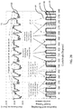
- FIG. 30 depicts the results of a control methodology configured to implement pumping according to a preferred phasing relationship in which none of injection events 64 are concurrent with actual pumping events 70 .
- partial pumping events 70 are generated as necessary during every other potential pumping event 66 to maintain rail pressure 62 to within a desired range.
- FIG. 30 shows this control methodology applied to a 1.5 pumping to injection ratio system, which FIG. 31 shows the same methodology applied to a 2 ⁇ pumping to injection ratio system.
- FIGS. 3-31 depict operation of control methodologies during steady-state engine operation, but the methodologies may also be employed during transient engine conditions. It should further be understood that multiple control methodologies may be employed as desired in response to changes in engine operating requirements or other influences. As mentioned above, in control methodologies that implement some combination of binary pumping, phased pumping, gentle pumping or pumping to minimize injection pressure variations, the relative importance of the goals corresponding to these modes of operation (e.g., efficiency, noise reduction, pump reliability and injection pressure control) may be weighted to achieve a customized set of operational goals.
- references to “one embodiment,” “an embodiment,” “an example embodiment,” etc. indicate that the embodiment described may include a particular feature, structure, or characteristic, but every embodiment may not necessarily include the particular feature, structure, or characteristic. Moreover, such phrases are not necessarily referring to the same embodiment. Further, when a particular feature, structure, or characteristic is described in connection with an embodiment, it is submitted that it is within the knowledge of one skilled in the art with the benefit of the present disclosure to affect such feature, structure, or characteristic in connection with other embodiments whether or not explicitly described. After reading the description, it will be apparent to one skilled in the relevant art(s) how to implement the disclosure in alternative embodiments.
Landscapes
- Engineering & Computer Science (AREA)
- Chemical & Material Sciences (AREA)
- Combustion & Propulsion (AREA)
- Mechanical Engineering (AREA)
- General Engineering & Computer Science (AREA)
- Fuel-Injection Apparatus (AREA)
- Electrical Control Of Air Or Fuel Supplied To Internal-Combustion Engine (AREA)
Abstract
Description
Claims (21)
Priority Applications (1)
| Application Number | Priority Date | Filing Date | Title |
|---|---|---|---|
| US16/344,764 US10968857B2 (en) | 2016-10-24 | 2017-10-24 | Fuel pump pressure control structure and methodology |
Applications Claiming Priority (3)
| Application Number | Priority Date | Filing Date | Title |
|---|---|---|---|
| US201662411943P | 2016-10-24 | 2016-10-24 | |
| US16/344,764 US10968857B2 (en) | 2016-10-24 | 2017-10-24 | Fuel pump pressure control structure and methodology |
| PCT/US2017/058078 WO2018081115A1 (en) | 2016-10-24 | 2017-10-24 | Fuel pump pressure control structure and methodology |
Publications (2)
| Publication Number | Publication Date |
|---|---|
| US20190331053A1 US20190331053A1 (en) | 2019-10-31 |
| US10968857B2 true US10968857B2 (en) | 2021-04-06 |
Family
ID=62025433
Family Applications (1)
| Application Number | Title | Priority Date | Filing Date |
|---|---|---|---|
| US16/344,764 Active 2037-12-21 US10968857B2 (en) | 2016-10-24 | 2017-10-24 | Fuel pump pressure control structure and methodology |
Country Status (4)
| Country | Link |
|---|---|
| US (1) | US10968857B2 (en) |
| EP (1) | EP3529480A4 (en) |
| CN (1) | CN110691901B (en) |
| WO (1) | WO2018081115A1 (en) |
Families Citing this family (4)
| Publication number | Priority date | Publication date | Assignee | Title |
|---|---|---|---|---|
| WO2020122890A1 (en) | 2018-12-12 | 2020-06-18 | Cummins Inc. | Rail pressure control for noise reduction |
| US11725604B2 (en) * | 2019-08-02 | 2023-08-15 | Cummins Inc. | Method for controlling pressure with a direct metered pump based on engine subcycle mass balance |
| WO2022108578A1 (en) * | 2020-11-18 | 2022-05-27 | Cummins Inc. | Fuel pump assembly |
| JP7586009B2 (en) * | 2021-07-16 | 2024-11-19 | トヨタ自動車株式会社 | Fuel pressure sensor abnormality diagnosis device |
Citations (26)
| Publication number | Priority date | Publication date | Assignee | Title |
|---|---|---|---|---|
| US4777921A (en) * | 1986-05-02 | 1988-10-18 | Nippondenso Co., Ltd. | Fuel injection system |
| US5094216A (en) | 1987-09-16 | 1992-03-10 | Nippondenso Co., Ltd. | Variable discharge high pressure pump |
| EP0501459A2 (en) | 1991-02-27 | 1992-09-02 | Nippondenso Co., Ltd. | Common-rail fuel injection system and related method |
| US5404855A (en) * | 1993-05-06 | 1995-04-11 | Cummins Engine Company, Inc. | Variable displacement high pressure pump for fuel injection systems |
| US6016791A (en) * | 1997-06-04 | 2000-01-25 | Detroit Diesel Corporation | Method and system for controlling fuel pressure in a common rail fuel injection system |
| US6192864B1 (en) * | 1999-06-15 | 2001-02-27 | Isuzu Motors Limited | Common-rail fuel-injection system |
| US6343588B1 (en) | 2000-03-01 | 2002-02-05 | Mitsubishi Denki Kabushiki Kaisha | Variable delivery fuel supply device |
| US20020033167A1 (en) * | 2000-09-18 | 2002-03-21 | Kenji Hiraku | Fuel supply system |
| EP1241349A2 (en) | 2001-03-15 | 2002-09-18 | Hitachi, Ltd. | Fuel supply apparatus and method of control thereof |
| US6725837B2 (en) * | 2001-03-15 | 2004-04-27 | Hitachi, Ltd. | Fuel supply system |
| US20040154594A1 (en) | 2003-02-06 | 2004-08-12 | Toyota Jidosha Kabushiki Kaisha | Fuel supply system for internal combustion engine |
| US20060021598A1 (en) | 2004-07-30 | 2006-02-02 | Toyota Jidosha Kabushiki Kaisha | Control device of high-pressure fuel system of internal combustion engine |
| US20060118089A1 (en) * | 2004-12-07 | 2006-06-08 | Hitachi, Ltd. | Controlling apparatus of variable capacity type fuel pump and fuel supply system |
| US7063073B2 (en) * | 2004-05-20 | 2006-06-20 | Magneti Marelli Powertrain, S.P.A. | Method for the direct injection of fuel into an internal combustion engine |
| US7073487B1 (en) | 2005-03-01 | 2006-07-11 | Mitsubishi Denki Kabushiki Kaisha | Fuel pressure control apparatus for multicylinder internal combustion engine |
| US7198034B2 (en) * | 2004-05-20 | 2007-04-03 | Magneti Marelli Powertrain Spa | Method and system for the direct injection of fuel into an internal combustion engine |
| US20070079809A1 (en) | 2005-10-07 | 2007-04-12 | Mitsubishi Denki Kabushiki Kaisha | High pressure fuel pump control apparatus for an engine |
| US20080127942A1 (en) | 2006-11-30 | 2008-06-05 | Mitsubishi Heavy Industries, Ltd. | Fuel injection apparatus for engine and method of operating the engine equipped with the apparatus |
| US7392790B2 (en) * | 2006-01-20 | 2008-07-01 | Caterpillar Inc. | System and method for resolving crossed electrical leads |
| US7406949B2 (en) | 2006-11-06 | 2008-08-05 | Caterpillar Inc. | Selective displacement control of multi-plunger fuel pump |
| US7568469B2 (en) * | 2005-10-19 | 2009-08-04 | Hitachi, Ltd. | Control device for a high-pressure fuel supply system using variable displacement fuel pump with reduced power consumption |
| US7823566B2 (en) | 2008-03-31 | 2010-11-02 | Caterpillar Inc | Vibration reducing system using a pump |
| US8015964B2 (en) | 2006-10-26 | 2011-09-13 | David Norman Eddy | Selective displacement control of multi-plunger fuel pump |
| US8516995B2 (en) | 2009-08-18 | 2013-08-27 | Delphi Technologies Holding S.Arl | Control method for a common rail fuel pump and apparatus for performing the same |
| EP2719887A1 (en) | 2012-10-12 | 2014-04-16 | Continental Automotive GmbH | A fuel injection pump |
| US9309849B2 (en) | 2011-03-23 | 2016-04-12 | Hitachi, Ltd | Method and apparatus for reducing the number of separately distinguishable noise peaks in a direct injection engine |
Family Cites Families (6)
| Publication number | Priority date | Publication date | Assignee | Title |
|---|---|---|---|---|
| DE69525986T2 (en) * | 1994-05-06 | 2002-12-19 | Cummins Engine Co Inc | Method and device for the electronic control of a storage fuel system |
| JP3310871B2 (en) * | 1996-07-08 | 2002-08-05 | 三菱電機株式会社 | Fuel injection device |
| JP2001152922A (en) * | 1999-11-26 | 2001-06-05 | Mitsubishi Motors Corp | Common rail fuel injector |
| JP4265659B2 (en) * | 2007-01-29 | 2009-05-20 | 株式会社デンソー | Fuel injection pressure control device |
| US7690353B2 (en) * | 2007-11-30 | 2010-04-06 | Caterpillar Inc. | Synchronizing common rail pumping events with engine operation |
| WO2015009692A1 (en) * | 2013-07-15 | 2015-01-22 | Cummins Inc. | System and method for fuel injector on-time calculation using fuel system pressure prediction |
-
2017
- 2017-10-24 CN CN201780065269.XA patent/CN110691901B/en active Active
- 2017-10-24 US US16/344,764 patent/US10968857B2/en active Active
- 2017-10-24 EP EP17865041.2A patent/EP3529480A4/en active Pending
- 2017-10-24 WO PCT/US2017/058078 patent/WO2018081115A1/en not_active Ceased
Patent Citations (31)
| Publication number | Priority date | Publication date | Assignee | Title |
|---|---|---|---|---|
| US4777921A (en) * | 1986-05-02 | 1988-10-18 | Nippondenso Co., Ltd. | Fuel injection system |
| US5094216A (en) | 1987-09-16 | 1992-03-10 | Nippondenso Co., Ltd. | Variable discharge high pressure pump |
| EP0501459A2 (en) | 1991-02-27 | 1992-09-02 | Nippondenso Co., Ltd. | Common-rail fuel injection system and related method |
| US5201294A (en) * | 1991-02-27 | 1993-04-13 | Nippondenso Co., Ltd. | Common-rail fuel injection system and related method |
| US5404855A (en) * | 1993-05-06 | 1995-04-11 | Cummins Engine Company, Inc. | Variable displacement high pressure pump for fuel injection systems |
| US6016791A (en) * | 1997-06-04 | 2000-01-25 | Detroit Diesel Corporation | Method and system for controlling fuel pressure in a common rail fuel injection system |
| US6192864B1 (en) * | 1999-06-15 | 2001-02-27 | Isuzu Motors Limited | Common-rail fuel-injection system |
| US6343588B1 (en) | 2000-03-01 | 2002-02-05 | Mitsubishi Denki Kabushiki Kaisha | Variable delivery fuel supply device |
| US20020033167A1 (en) * | 2000-09-18 | 2002-03-21 | Kenji Hiraku | Fuel supply system |
| EP1241349A2 (en) | 2001-03-15 | 2002-09-18 | Hitachi, Ltd. | Fuel supply apparatus and method of control thereof |
| US6701898B2 (en) * | 2001-03-15 | 2004-03-09 | Hitachi, Ltd. | Fuel supply apparatus and method of control thereof |
| US6725837B2 (en) * | 2001-03-15 | 2004-04-27 | Hitachi, Ltd. | Fuel supply system |
| US20040154594A1 (en) | 2003-02-06 | 2004-08-12 | Toyota Jidosha Kabushiki Kaisha | Fuel supply system for internal combustion engine |
| US7198034B2 (en) * | 2004-05-20 | 2007-04-03 | Magneti Marelli Powertrain Spa | Method and system for the direct injection of fuel into an internal combustion engine |
| US7063073B2 (en) * | 2004-05-20 | 2006-06-20 | Magneti Marelli Powertrain, S.P.A. | Method for the direct injection of fuel into an internal combustion engine |
| US20060021598A1 (en) | 2004-07-30 | 2006-02-02 | Toyota Jidosha Kabushiki Kaisha | Control device of high-pressure fuel system of internal combustion engine |
| US20060118089A1 (en) * | 2004-12-07 | 2006-06-08 | Hitachi, Ltd. | Controlling apparatus of variable capacity type fuel pump and fuel supply system |
| US7559313B2 (en) | 2004-12-07 | 2009-07-14 | Hitachi, Ltd. | Controlling apparatus of variable capacity type fuel pump and fuel supply system |
| US7073487B1 (en) | 2005-03-01 | 2006-07-11 | Mitsubishi Denki Kabushiki Kaisha | Fuel pressure control apparatus for multicylinder internal combustion engine |
| US20070079809A1 (en) | 2005-10-07 | 2007-04-12 | Mitsubishi Denki Kabushiki Kaisha | High pressure fuel pump control apparatus for an engine |
| US7568469B2 (en) * | 2005-10-19 | 2009-08-04 | Hitachi, Ltd. | Control device for a high-pressure fuel supply system using variable displacement fuel pump with reduced power consumption |
| US7392790B2 (en) * | 2006-01-20 | 2008-07-01 | Caterpillar Inc. | System and method for resolving crossed electrical leads |
| US8015964B2 (en) | 2006-10-26 | 2011-09-13 | David Norman Eddy | Selective displacement control of multi-plunger fuel pump |
| US8136508B2 (en) | 2006-10-26 | 2012-03-20 | Caterpillar Inc. | Selective displacement control of multi-plunger fuel pump |
| US7406949B2 (en) | 2006-11-06 | 2008-08-05 | Caterpillar Inc. | Selective displacement control of multi-plunger fuel pump |
| US7490592B2 (en) * | 2006-11-30 | 2009-02-17 | Mitsubishi Heavy Industries, Ltd. | Fuel injection apparatus for engine and method of operating the engine equipped with the apparatus |
| US20080127942A1 (en) | 2006-11-30 | 2008-06-05 | Mitsubishi Heavy Industries, Ltd. | Fuel injection apparatus for engine and method of operating the engine equipped with the apparatus |
| US7823566B2 (en) | 2008-03-31 | 2010-11-02 | Caterpillar Inc | Vibration reducing system using a pump |
| US8516995B2 (en) | 2009-08-18 | 2013-08-27 | Delphi Technologies Holding S.Arl | Control method for a common rail fuel pump and apparatus for performing the same |
| US9309849B2 (en) | 2011-03-23 | 2016-04-12 | Hitachi, Ltd | Method and apparatus for reducing the number of separately distinguishable noise peaks in a direct injection engine |
| EP2719887A1 (en) | 2012-10-12 | 2014-04-16 | Continental Automotive GmbH | A fuel injection pump |
Non-Patent Citations (2)
| Title |
|---|
| International Preliminary Report on Patentability issued by the IPEA/US, Commissioner for Patents, dated Feb. 5, 2019, for International Application No. PCT/US2017/058078; 11 pages. |
| International Search Report and Written Opinion issued by the ISA/US, Commissioner for Patents, dated Jan. 4, 2018, for International Application No. PCT/US2017/058078; 13 pages. |
Also Published As
| Publication number | Publication date |
|---|---|
| CN110691901A (en) | 2020-01-14 |
| EP3529480A4 (en) | 2020-07-01 |
| US20190331053A1 (en) | 2019-10-31 |
| CN110691901B (en) | 2022-11-08 |
| WO2018081115A1 (en) | 2018-05-03 |
| EP3529480A1 (en) | 2019-08-28 |
Similar Documents
| Publication | Publication Date | Title |
|---|---|---|
| US10968857B2 (en) | Fuel pump pressure control structure and methodology | |
| US9587579B2 (en) | Current pulsing control methods for lift fuel pumps | |
| CN101994575B (en) | For the controlling method of common rail fuel pump and the device for performing the method | |
| JP2001263198A (en) | Fuel pump and fuel supply device using it | |
| CN101878364B (en) | Synchronizing common rail pumping events with engine operation | |
| US9874185B2 (en) | Direct injection pump control for low fuel pumping volumes | |
| JP2009270520A (en) | Fuel pressure controller and fuel pressure control system | |
| JP2003113758A (en) | Methods, computer programs, open-loop and / or closed-loop control devices and fuel systems for operating internal combustion engines, for example direct injection | |
| US7216628B2 (en) | Fuel injection apparatus having common rail and subject device control system | |
| JP6034494B2 (en) | Fuel pump device | |
| US9435286B2 (en) | Method to reduce fuel system power consumption | |
| US11725604B2 (en) | Method for controlling pressure with a direct metered pump based on engine subcycle mass balance | |
| JP3577991B2 (en) | Common rail fuel pressure control system for internal combustion engines | |
| EP3267029B1 (en) | Fuel pump with an improved maximum-pressure valve for a direct-injection system | |
| JPH09222056A (en) | Fuel injection device | |
| EP2796705A1 (en) | Fuel injection system and fuel pump | |
| JPH1162772A (en) | Accumulating type fuel supply device | |
| JP4650449B2 (en) | Fuel supply device | |
| US11668261B2 (en) | Pump active inlet valve spilling residual pressure | |
| US11486386B2 (en) | Active control valve for a fluid pump | |
| CN106968820A (en) | Method and computer program and control and/or adjusting apparatus for running internal combustion engine | |
| JP3999878B2 (en) | Variable discharge high-pressure pump and common rail fuel injection control apparatus using the variable discharge high-pressure pump | |
| JP2008045487A (en) | Supply pump | |
| JPH1182222A (en) | Common rail fuel injection control device | |
| JP2005226618A (en) | Accumulated fuel injection system |
Legal Events
| Date | Code | Title | Description |
|---|---|---|---|
| FEPP | Fee payment procedure |
Free format text: ENTITY STATUS SET TO UNDISCOUNTED (ORIGINAL EVENT CODE: BIG.); ENTITY STATUS OF PATENT OWNER: LARGE ENTITY |
|
| AS | Assignment |
Owner name: CUMMINS INC., INDIANA Free format text: ASSIGNMENT OF ASSIGNORS INTEREST;ASSIGNORS:BENSON, DONALD J.;PEAVLER, PAUL;SIGNING DATES FROM 20180126 TO 20180803;REEL/FRAME:048992/0089 |
|
| STPP | Information on status: patent application and granting procedure in general |
Free format text: DOCKETED NEW CASE - READY FOR EXAMINATION |
|
| STPP | Information on status: patent application and granting procedure in general |
Free format text: NON FINAL ACTION MAILED |
|
| STPP | Information on status: patent application and granting procedure in general |
Free format text: NOTICE OF ALLOWANCE MAILED -- APPLICATION RECEIVED IN OFFICE OF PUBLICATIONS |
|
| STPP | Information on status: patent application and granting procedure in general |
Free format text: PUBLICATIONS -- ISSUE FEE PAYMENT RECEIVED |
|
| STPP | Information on status: patent application and granting procedure in general |
Free format text: PUBLICATIONS -- ISSUE FEE PAYMENT VERIFIED |
|
| STCF | Information on status: patent grant |
Free format text: PATENTED CASE |
|
| MAFP | Maintenance fee payment |
Free format text: PAYMENT OF MAINTENANCE FEE, 4TH YEAR, LARGE ENTITY (ORIGINAL EVENT CODE: M1551); ENTITY STATUS OF PATENT OWNER: LARGE ENTITY Year of fee payment: 4 |
|
| AS | Assignment |
Owner name: CUMMINS SCANIA HPCR SYSTEM, LLC, INDIANA Free format text: ASSIGNMENT OF ASSIGNORS INTEREST;ASSIGNOR:CUMMINS INC.;REEL/FRAME:073461/0792 Effective date: 20251103 |