US10967147B2 - Reliability determination of electrode location data - Google Patents
Reliability determination of electrode location data Download PDFInfo
- Publication number
- US10967147B2 US10967147B2 US16/456,439 US201916456439A US10967147B2 US 10967147 B2 US10967147 B2 US 10967147B2 US 201916456439 A US201916456439 A US 201916456439A US 10967147 B2 US10967147 B2 US 10967147B2
- Authority
- US
- United States
- Prior art keywords
- electrode
- electrodes
- catheter
- medical device
- processor
- Prior art date
- Legal status (The legal status is an assumption and is not a legal conclusion. Google has not performed a legal analysis and makes no representation as to the accuracy of the status listed.)
- Active, expires
Links
Images


Classifications
-
- A—HUMAN NECESSITIES
- A61—MEDICAL OR VETERINARY SCIENCE; HYGIENE
- A61B—DIAGNOSIS; SURGERY; IDENTIFICATION
- A61B34/00—Computer-aided surgery; Manipulators or robots specially adapted for use in surgery
- A61B34/20—Surgical navigation systems; Devices for tracking or guiding surgical instruments, e.g. for frameless stereotaxis
-
- A—HUMAN NECESSITIES
- A61—MEDICAL OR VETERINARY SCIENCE; HYGIENE
- A61M—DEVICES FOR INTRODUCING MEDIA INTO, OR ONTO, THE BODY; DEVICES FOR TRANSDUCING BODY MEDIA OR FOR TAKING MEDIA FROM THE BODY; DEVICES FOR PRODUCING OR ENDING SLEEP OR STUPOR
- A61M25/00—Catheters; Hollow probes
- A61M25/01—Introducing, guiding, advancing, emplacing or holding catheters
- A61M25/0105—Steering means as part of the catheter or advancing means; Markers for positioning
-
- A—HUMAN NECESSITIES
- A61—MEDICAL OR VETERINARY SCIENCE; HYGIENE
- A61B—DIAGNOSIS; SURGERY; IDENTIFICATION
- A61B1/00—Instruments for performing medical examinations of the interior of cavities or tubes of the body by visual or photographical inspection, e.g. endoscopes; Illuminating arrangements therefor
- A61B1/00002—Operational features of endoscopes
- A61B1/00004—Operational features of endoscopes characterised by electronic signal processing
-
- A—HUMAN NECESSITIES
- A61—MEDICAL OR VETERINARY SCIENCE; HYGIENE
- A61B—DIAGNOSIS; SURGERY; IDENTIFICATION
- A61B17/00—Surgical instruments, devices or methods
-
- A—HUMAN NECESSITIES
- A61—MEDICAL OR VETERINARY SCIENCE; HYGIENE
- A61B—DIAGNOSIS; SURGERY; IDENTIFICATION
- A61B90/00—Instruments, implements or accessories specially adapted for surgery or diagnosis and not covered by any of the groups A61B1/00 - A61B50/00, e.g. for luxation treatment or for protecting wound edges
- A61B90/06—Measuring instruments not otherwise provided for
-
- A—HUMAN NECESSITIES
- A61—MEDICAL OR VETERINARY SCIENCE; HYGIENE
- A61B—DIAGNOSIS; SURGERY; IDENTIFICATION
- A61B90/00—Instruments, implements or accessories specially adapted for surgery or diagnosis and not covered by any of the groups A61B1/00 - A61B50/00, e.g. for luxation treatment or for protecting wound edges
- A61B90/08—Accessories or related features not otherwise provided for
-
- G06T5/002—
-
- G—PHYSICS
- G06—COMPUTING OR CALCULATING; COUNTING
- G06T—IMAGE DATA PROCESSING OR GENERATION, IN GENERAL
- G06T5/00—Image enhancement or restoration
- G06T5/70—Denoising; Smoothing
-
- G—PHYSICS
- G06—COMPUTING OR CALCULATING; COUNTING
- G06T—IMAGE DATA PROCESSING OR GENERATION, IN GENERAL
- G06T7/00—Image analysis
- G06T7/70—Determining position or orientation of objects or cameras
-
- A—HUMAN NECESSITIES
- A61—MEDICAL OR VETERINARY SCIENCE; HYGIENE
- A61B—DIAGNOSIS; SURGERY; IDENTIFICATION
- A61B17/00—Surgical instruments, devices or methods
- A61B2017/00017—Electrical control of surgical instruments
- A61B2017/00022—Sensing or detecting at the treatment site
- A61B2017/00026—Conductivity or impedance, e.g. of tissue
-
- A—HUMAN NECESSITIES
- A61—MEDICAL OR VETERINARY SCIENCE; HYGIENE
- A61B—DIAGNOSIS; SURGERY; IDENTIFICATION
- A61B17/00—Surgical instruments, devices or methods
- A61B2017/00017—Electrical control of surgical instruments
- A61B2017/00022—Sensing or detecting at the treatment site
- A61B2017/00039—Electric or electromagnetic phenomena other than conductivity, e.g. capacity, inductivity, Hall effect
- A61B2017/00044—Sensing electrocardiography, i.e. ECG
- A61B2017/00048—Spectral analysis
- A61B2017/00053—Mapping
-
- A—HUMAN NECESSITIES
- A61—MEDICAL OR VETERINARY SCIENCE; HYGIENE
- A61B—DIAGNOSIS; SURGERY; IDENTIFICATION
- A61B34/00—Computer-aided surgery; Manipulators or robots specially adapted for use in surgery
- A61B34/20—Surgical navigation systems; Devices for tracking or guiding surgical instruments, e.g. for frameless stereotaxis
- A61B2034/2046—Tracking techniques
- A61B2034/2051—Electromagnetic tracking systems
-
- A—HUMAN NECESSITIES
- A61—MEDICAL OR VETERINARY SCIENCE; HYGIENE
- A61B—DIAGNOSIS; SURGERY; IDENTIFICATION
- A61B90/00—Instruments, implements or accessories specially adapted for surgery or diagnosis and not covered by any of the groups A61B1/00 - A61B50/00, e.g. for luxation treatment or for protecting wound edges
- A61B90/06—Measuring instruments not otherwise provided for
- A61B2090/061—Measuring instruments not otherwise provided for for measuring dimensions, e.g. length
-
- A—HUMAN NECESSITIES
- A61—MEDICAL OR VETERINARY SCIENCE; HYGIENE
- A61B—DIAGNOSIS; SURGERY; IDENTIFICATION
- A61B90/00—Instruments, implements or accessories specially adapted for surgery or diagnosis and not covered by any of the groups A61B1/00 - A61B50/00, e.g. for luxation treatment or for protecting wound edges
- A61B90/06—Measuring instruments not otherwise provided for
- A61B2090/067—Measuring instruments not otherwise provided for for measuring angles
-
- A—HUMAN NECESSITIES
- A61—MEDICAL OR VETERINARY SCIENCE; HYGIENE
- A61B—DIAGNOSIS; SURGERY; IDENTIFICATION
- A61B90/00—Instruments, implements or accessories specially adapted for surgery or diagnosis and not covered by any of the groups A61B1/00 - A61B50/00, e.g. for luxation treatment or for protecting wound edges
- A61B90/08—Accessories or related features not otherwise provided for
- A61B2090/0807—Indication means
- A61B2090/0811—Indication means for the position of a particular part of an instrument with respect to the rest of the instrument, e.g. position of the anvil of a stapling instrument
-
- A—HUMAN NECESSITIES
- A61—MEDICAL OR VETERINARY SCIENCE; HYGIENE
- A61M—DEVICES FOR INTRODUCING MEDIA INTO, OR ONTO, THE BODY; DEVICES FOR TRANSDUCING BODY MEDIA OR FOR TAKING MEDIA FROM THE BODY; DEVICES FOR PRODUCING OR ENDING SLEEP OR STUPOR
- A61M25/00—Catheters; Hollow probes
- A61M25/01—Introducing, guiding, advancing, emplacing or holding catheters
- A61M25/0105—Steering means as part of the catheter or advancing means; Markers for positioning
- A61M2025/0166—Sensors, electrodes or the like for guiding the catheter to a target zone, e.g. image guided or magnetically guided
-
- G—PHYSICS
- G06—COMPUTING OR CALCULATING; COUNTING
- G06T—IMAGE DATA PROCESSING OR GENERATION, IN GENERAL
- G06T2207/00—Indexing scheme for image analysis or image enhancement
- G06T2207/30—Subject of image; Context of image processing
- G06T2207/30004—Biomedical image processing
- G06T2207/30021—Catheter; Guide wire
-
- G—PHYSICS
- G06—COMPUTING OR CALCULATING; COUNTING
- G06V—IMAGE OR VIDEO RECOGNITION OR UNDERSTANDING
- G06V2201/00—Indexing scheme relating to image or video recognition or understanding
- G06V2201/03—Recognition of patterns in medical or anatomical images
- G06V2201/034—Recognition of patterns in medical or anatomical images of medical instruments
Definitions
- the present disclosure relates generally to determining a reliability of location data received from an electrode.
- Medical devices, catheters, and/or cardiovascular catheters can be used in a variety of diagnostic, therapeutic, mapping and/or ablative procedures to diagnose and/or correct conditions such as atrial arrhythmias, including for example, ectopic atrial tachycardia, atrial fibrillation, and atrial flutter.
- a medical device can be threaded through a vasculature of a patient to a site where the diagnostic, therapeutic, mapping, and/or ablative procedure to diagnose and/or correct the condition is performed.
- Sensors e.g., electrodes, magnetic positioning sensors
- Sensors can be placed on the medical device, which can receive signals that are generated proximate to the patient from a device. Based on the received signals, an orientation and/or position of the medical device within a heart can be computed.
- One technique for determining the position and orientation of a catheter within a body is by tracking a plurality of sensors on the catheter using a position sensing and navigation system (sometimes called a location mapping system).
- the sensors can include electrodes disposed on the catheter, which can provide voltage measurements associated with their exposure to an electrical field generated through excitation of pairs of electrodes on an outer surface of the body. Voltage measurements on the catheter electrodes can then be used to determine the position and orientation of the catheter electrodes within a coordinate system of the position sensing and navigation system.
- Other exemplary position sensing and navigation systems include magnetic systems.
- the determined position and orientation of the catheter sensors is often used to render an image of the catheter relative to surrounding tissues, including heart tissues.
- One drawback to conventional systems is that the determined position and orientation of the catheter sensors can include errors due to errors associated with data received from the catheter electrodes. For example, some of the catheter electrodes may be misconnected, may be disconnected, and/or may be faulty. These errors can distort the rendered shape of the catheter from its true mechanical shape in the resulting image.
- Embodiments of the present disclosure include a system for determining an error associated with an electrode disposed on a medical device.
- the system comprises a processor and a memory storing instructions on a non-transitory computer-readable medium.
- the instructions are executable by the processor to receive an electrode signal from the electrode disposed on the medical device.
- the instructions are further executable by the processor to receive a plurality of other electrode signals from a plurality of other electrodes disposed on the medical device.
- the instructions are further executable by the processor to determine that the electrode signal received from the electrode disposed on the medical device is an outlier in relation to the plurality of other electrode signals from the plurality of other electrodes disposed on the medical device, based on a comparison between the electrode signal and the plurality of other electrode signals.
- Embodiments of the present disclosure include a method for determining an error associated with an electrode disposed on a medical device.
- the method can comprise receiving an electrode signal from the electrode disposed on the medical device.
- the method can comprise receiving a plurality of other electrode signals from a plurality of other electrodes disposed on the medical device.
- the method can comprise determining impedance based coordinates for the electrode from the electrode signal and for the plurality of other electrodes from the plurality of other electrode signals.
- the method can comprise determining that the impedance based coordinates for the electrode disposed on the medical device is an outlier in relation the plurality of other impedance based coordinates for the plurality of other electrodes disposed on the medical device, based on a comparison between the impedance based coordinates for the electrode and the plurality of other impedance based coordinates for the plurality of other electrodes.
- the method can comprise excluding the impedance based coordinates for the electrode disposed on the medical device that is determined to be an outlier in determination of a shape of the catheter.
- Embodiments of the present disclosure include a system for determining an error associated with an electrode disposed on a medical device.
- the system comprises a processor and a memory storing instructions on a non-transitory computer-readable medium.
- the instructions are executable by the processor to acquire data points corresponding to measured positions of a plurality of electrodes disposed on the medical device.
- the instructions are further executable by the processor to parameterize the catheter to determine true positions of the plurality of electrodes disposed on the medical device.
- the instructions are further executable by the processor to calculate synthetic parameters from the measured positions of the plurality of electrodes and the true positions of the plurality of electrodes.
- the instructions are further executable by the processor to filter the synthetic parameters.
- the instructions are further executable by the processor to generate the smoothed image of the catheter using the filtered synthetic parameters.
- FIG. 1 is a diagrammatic view of an exemplary system for performing one or more diagnostic or therapeutic procedures, wherein the system comprises an impedance based medical positioning system, in accordance with embodiments of the present disclosure.
- FIG. 2A depicts an electrophysiology catheter, in accordance with embodiments of the present disclosure.
- FIG. 2B depicts an unfiltered graphical representation of unfiltered electrode positions that includes an unfiltered electrode position of a disconnected electrode and a filtered graphical representation of filtered electrode positions, in accordance with embodiments of the present disclosure.
- FIG. 2C depicts an unfiltered graphical representation of unfiltered electrode positions that includes an unfiltered electrode position of a misconnected electrode and a filtered graphical representation of filtered electrode positions, in accordance with embodiments of the present disclosure.
- FIG. 3 depicts an unfiltered graphical representation of unfiltered electrode positions and a filtered graphical representation of filtered electrode positions, in accordance with embodiments of the present disclosure.
- FIG. 4 depicts one embodiment of a planar catheter that may be used with the system shown in FIG. 1 , in accordance with embodiments of the present disclosure.
- FIG. 5 depicts one embodiment of a curved catheter that may be used with the system shown in FIG. 1 , in accordance with embodiments of the present disclosure.
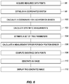
- FIG. 6 depicts a method for generating a smoothed image of an elongate medical device in a body is illustrated, in accordance with embodiments of the present disclosure.
- FIG. 1 is a diagrammatic overview of a catheter system in which the invention may be practiced.
- the system may comprise various visualization, mapping and navigation components as known in the art, including among others, for example, an EnSiteTM VelocityTM Cardiac Mapping and Visualization System commercially available from St. Jude Medical, Inc., or as seen generally by reference to U.S. Pat. No. 7,263,397, owned by the common assignee of the present invention, and hereby incorporated by reference in its entirety.
- the system may be used in connection with or for various medical procedures, for example, mapping of the heart and/or cardiac ablation procedures.
- the medical positioning system 14 may comprise a magnetic field-based system such as, for example, the CartoTM System available from Biosense Webster, and as generally shown with reference to one or more of U.S. Pat. Nos. 6,498,944; 6,788,967; and 6,690,963, the entire disclosures of which are incorporated herein by reference, or the MediGuideTM system from MediGuide Ltd. (now owned by St. Jude Medical, Inc.), and as generally shown with reference to one or more of U.S. Pat. Nos.
- the medical positioning system 14 may comprise a combination magnetic field-based system and electric field-based system such as, for example and without limitation, the Carto 3TM System also available from Biosense Webster.
- Carto 3TM System also available from Biosense Webster.
- the catheter system includes a diagrammatic depiction of a heart 10 of a patient 11 .
- the system includes the ability to receive a plurality of catheter locations as the catheter distal end is swept around and within a chamber of the heart.
- FIG. 1 shows an exemplary catheter localization system of the type based on externally-applied orthogonal electric fields which are used to determine the location of one or more catheter position sensors.
- Such a system is known generally in the art (e.g., an EnSite NAVXTM Navigation and Visualization System). It should be understood, however, that this embodiment is exemplary only and not limiting in nature.
- a sensor is provided for producing signals indicative of catheter location information, and may include one or more position sensors.
- the position sensors can include one or more electrodes configured to detect one or more characteristics of an electrical field, for example in the case of an impedance-based localization system, or alternatively, one or more coils (e.g., wire windings) configured to detect one or more characteristics of a magnetic field, for example, in the case of a magnetic-field based localization system.
- one or more coils e.g., wire windings
- one or more position sensors may collectively define the sensor.
- the one or more position sensors may be provided on a distal end of a catheter and the localization system may be configured to obtain location information from the one or more position sensors.
- the localization system may compute a distal location of the catheter using not only the received location information, but also a geometrical relationship between the one or more position sensors providing the location information and the distal location on the catheter (e.g., one piece of geometrical information may be the ring electrode to tip distance).
- the localization system may use the computed location, as if it were collected directly.
- the catheter tip and the magnetic coil may have a geometrical relationship therebetween where the localization system is configured to use the computed tip location (i.e., computed based on the magnetic coil signals and predefined knowledge of the geometrical relationship between coil and tip) as if such location were collected directly.
- the computed tip location i.e., computed based on the magnetic coil signals and predefined knowledge of the geometrical relationship between coil and tip
- X-axis electrodes 12 , 14 three sets of surface electrodes (e.g., applied via a patch) are shown: X-axis electrodes 12 , 14 ; Y-axis electrodes 18 , 19 ; and Z-axis electrodes 16 , 22 .
- an additional surface electrode 21 e.g., applied via a “belly” patch
- the surface electrodes are all connected to a switch 24 .
- a representative catheter 13 is shown, which has a single distal electrode 17 , which may be referred to herein as a “roving” or “measurement” electrode.
- the catheter 13 can be a coronary sinus catheter or a right ventricle apex catheter.
- FIG. 1 also shows a second, independent catheter 29 with a fixed reference electrode 31 , which may be stationary on the heart 10 for calibration purposes.
- FIG. 1 further shows a computer system 20 , a signal generator 25 , an analog-to-digital converter 26 and a low-pass filter 27 .
- the computer system 20 can utilize software, hardware, firmware, and/or logic to perform a number of functions described herein.
- the computing system 20 can be a combination of hardware and instructions to share information.
- the hardware for example can include processing resource 32 and/or a memory resource 33 (e.g., non-transitory computer-readable medium (CRM) database, etc.).
- a processing resource 32 can include a number of processors capable of executing instructions stored by the memory resource 33 .
- Processing resource 32 can be integrated in a single device or distributed across multiple devices.
- the instructions e.g., computer-readable instructions (CRI)
- CRM computer-readable instructions
- the computer system 20 is configured to control the signal generator 25 in accordance with predetermined strategies to selectively energize various pairs of surface electrodes.
- the computer system 20 is configured to obtain raw patch data (i.e., voltage readings) via the filter 27 and A-D converter 26 and use this raw patch data to determine the raw electrode location coordinates in three-dimensional space (X, Y, Z) of a catheter electrode positioned inside the heart 10 or chamber thereof (e.g., such as the roving electrode 17 mentioned above).
- a phase of the patient's 11 cardiac cycle can be measured or otherwise determined when such electrode location coordinates are being received.
- most or all of the conventional twelve (12) ECG leads, coupled to body surface electrodes and designated collectively by reference numeral 15 are provided to support the acquisition of an electrocardiogram (ECG) of the patient 11 .
- ECG electrocardiogram
- a reference electrode positioned in a fixed location in the heart 10 may be used to provide a relatively stable signal that can be analyzed to determine the cardiac phase of the heart 10 in the cardiac cycle (e.g., placed at the coronary sinus).
- another catheter having an electrode, other than the moving or roving catheter may be placed and maintained in a constant position relative to the heart 10 to obtain a relatively stable signal indicative of cardiac phase.
- the ECG leads 15 are coupled directly to the computer system 20 for acquisition and subsequent processing to obtain the phase of the heart 10 in the cardiac cycle.
- the ECG leads 15 may also be provided to other systems (not shown).
- embodiments of the present disclosure can be used with a magnetic field-based system.
- Some embodiments can include a main electronic control unit (e.g., one or more processors) having various input/output mechanisms, a display, an optional image database, a localization system such as a medical positioning system (MPS) (electromagnetic sensor tracking system), an electrocardiogram (ECG) monitor, one or more MPS location sensors (e.g., patient reference sensor), and an MPS-enabled medical device (such as an elongated catheter or introducer) which itself includes one or more of the above-described MPS location sensors.
- MPS medical positioning system
- ECG electrocardiogram
- MPS location sensors e.g., patient reference sensor
- MPS-enabled medical device such as an elongated catheter or introducer
- the medical positioning system may comprise a magnetic field-based system such as, for example, the MediGuideTM system from MediGuide Ltd. (now owned by St. Jude Medical, Inc.), and as generally shown with reference to one or more of U.S. Pat. Nos. 6,233,476; 7,197,354; and 7,386,339, the entire disclosures of which are incorporated herein by reference.
- a magnetic field-based system such as, for example, the MediGuideTM system from MediGuide Ltd. (now owned by St. Jude Medical, Inc.), and as generally shown with reference to one or more of U.S. Pat. Nos. 6,233,476; 7,197,354; and 7,386,339, the entire disclosures of which are incorporated herein by reference.
- Embodiments can include input/output mechanisms, which can comprise conventional apparatus for interfacing with a computer-based control unit, for example, a keyboard, a mouse, a tablet, a foot pedal, a switch or the like.
- a computer-based control unit for example, a keyboard, a mouse, a tablet, a foot pedal, a switch or the like.
- Embodiments can also include a display, which can also comprise conventional apparatus.
- the magnetic field-based system may optionally include an image database.
- the image database may be configured to store image information relating to the patient's body, for example, a region of interest surrounding a destination site for the medical device and/or multiple regions of interest along a navigation path contemplated to be traversed by the device to reach the destination site.
- the image data in the image database may comprise known image types including (1) one or more two-dimensional still images acquired at respective, individual times in the past; (2) a plurality of related two-dimensional images obtained in real-time from an image acquisition device (e.g., fluoroscopic images from an x-ray imaging apparatus) wherein the image database acts as a buffer (live fluoroscopy); and/or (3) a sequence of related two-dimensional images defining a cine-loop (CL), wherein each image in the sequence has at least an ECG timing parameter associated therewith adequate to allow playback of the sequence in accordance with acquired real-time ECG signals obtained from the ECG monitor.
- an image acquisition device e.g., fluoroscopic images from an x-ray imaging apparatus
- CL cine-loop
- each image in the sequence has at least an ECG timing parameter associated therewith adequate to allow playback of the sequence in accordance with acquired real-time ECG signals obtained from the ECG monitor.
- the image database may also include three-dimensional image data.
- the images may be acquired through
- the MPS can be configured to serve as the localization system and therefore to determine positioning (localization) data with respect to one or more of MPS location sensors, one or more medical devices, and/or on one or more patient reference sensors (PRS), and output a respective location reading.
- the location readings may each include at least one or both of a position and an orientation (P&O) relative to a reference coordinate system, which may be the coordinate system of the MPS.
- P&O may be expressed as a position (i.e., a coordinate in three axes X, Y, and Z) and orientation (i.e., an azimuth and elevation) of a magnetic field sensor in a magnetic field relative to a magnetic field generator(s) or transmitter(s).
- the MPS determines respective locations (i.e., P&O) in the reference coordinate system based on capturing and processing signals received from the magnetic field sensors, while such sensors are disposed in a controlled low-strength AC magnetic field. From an electromagnetic perspective, these sensors develop a voltage that is induced on the coil residing in a changing magnetic field, as contemplated here.
- the sensors are thus configured to detect one or more characteristics of the magnetic field(s) in which they are disposed and to generate an indicative signal, which is further processed by the MPS to obtain a respective P&O of the sensors. Exemplary design features and manufacturing processes and methods for the sensors and medical devices incorporating such sensors may be found in U.S. Pat. No. 8,636,718, the entirety of which is incorporated by reference herein.
- the MPS sensor may be associated with the MPS-enabled medical device.
- Another MPS sensor namely, a patient reference sensor (PRS) is configured to provide a positional reference of the patient's body so as to allow motion compensation for gross patient body movements and/or respiration-induced movements.
- the PRS may be attached to the patient's manubrium sternum, a stable place on the chest, or another location that is relatively positionally stable.
- the PRS is configured to detect one or more characteristics of the magnetic field in which it is disposed, wherein the MPS provides a location reading (e.g., a P&O reading) indicative of the PRS's position and orientation in the reference coordinate system.
- a location reading e.g., a P&O reading
- the electro-cardiogram (ECG) monitor is configured to continuously detect an electrical timing signal of the heart organ through the use of a plurality of ECG electrodes (not shown), which may be externally-affixed to the outside of a patient's body.
- the timing signal generally corresponds to the particular phase of the cardiac cycle, among other things.
- the ECG signal(s) may be used by the control unit for ECG synchronized playback of a previously captured sequence of images (cine loop) stored in the database.
- the ECG monitor and the ECG-electrodes may both comprise conventional components.
- the magnetic field-based system can be incorporated into or associated with a fluoroscopic imaging system, which may include commercially available fluoroscopic imaging components, for example, an x-ray source, a C-Arm, and/or an x-ray image intensifier or detector (i.e., “Catheter Lab”).
- the MPS electronic sensor tracking system
- the MTA includes a magnetic transmitter assembly (MTA) (electromagnetic field generator) and a magnetic processing core for determining location (P&O) readings.
- the MTA is configured to generate the magnetic field(s) in and around the patient's chest cavity, in a predefined three-dimensional space identified as a motion box.
- the MPS sensors are, as described above, configured to sense one or more characteristics of the magnetic field(s) when the sensors are in a motion box, and each generate a respective signal that is provided to the magnetic processing core.
- the processing core is responsive to these detected signals and is configured to calculate respective P&O readings for each MPS sensor in the motion box.
- the processing core can detect when an MPS sensor exits the motion box.
- the MPS enables real-time tracking of each sensor in three-dimensional space.
- the actual volume of the motion box may be stored in, for example, the processing core, and processing core is able to determine the positions and orientations of each sensor in relation to the boundaries of motion box.
- the actual volume of motion box may be stored in, for example, the main control, and the main control may be able to determine the positions and orientations of each sensor in relation to the boundaries of the motion box. Accordingly, the system can evaluate (e.g., in the processing core or in the main control) whether a sensor is within, at the boundary of, or outside of the motion box. Based on this information, the motion box and sensor(s) can be displayed in relation to one another on the display as described in greater detail elsewhere herein.
- the MTA can be located underneath a patient examination table, between an x-ray source and the patient examination table.
- the MTA can be connected with the patient examination table.
- the MTA can be a mobile device, which can be placed on a chest of the patient and used to generate the magnetic field for tracking of the object.
- the positional relationship between the image coordinate system and the MPS reference coordinate system may be calculated based on a known optical-magnetic calibration of the system (e.g., established during setup), since the positioning system and imaging system may be considered fixed relative to each other in such an embodiment.
- a registration step registering the MPS coordinate system and the image coordinate system may need to be performed so that MPS location readings can be properly coordinated with any particular image being used.
- FIG. 2A depicts an electrophysiology catheter 40 A, in accordance with embodiments of the present disclosure.
- the electrophysiology catheter 40 A can be used in an electrophysiology procedure to help doctors understand a nature of abnormal heart rhythms (e.g., arrhythmias).
- the procedure is performed by inserting the electrophysiology catheter 40 A, which measures electrical activity, through blood vessels that enter the heart.
- Each electrophysiology catheter 40 A can include several electrodes 46 - 1 A, 46 - 2 A, . . . , 46 - 12 A connected to a computer system (e.g., computer system 20 in FIG. 1 ) via a connection box.
- the electrodes 46 - 1 A, 46 - 2 A, . . . , 46 - 12 A are referred to in the plural as electrodes 46 A.
- the electrophysiology catheter 40 A can include a magnetic position sensor (not depicted), in some embodiments.
- the electrodes can detect one or more characteristics of an electrical field in which the electrodes 46 A are disposed.
- the electrical field can be produced by surface electrodes (e.g., patch electrodes) placed on an exterior of the patient. Based on the impedances associated with signals received from the electrodes 46 A, a position (e.g., coordinates) of the electrophysiology catheter 40 A can be determined.
- the electrophysiology catheter 40 A can be an AdvisorTM FL Circular Mapping Catheter, Sensor EnabledTM, as produced by St.
- electrophysiology catheter 40 A can be another type of electrophysiology catheter in some embodiments.
- the catheter 40 A can be used in conjunction with an EnSiteTM VelocityTM Cardiac Mapping and Visualization System and/or a MediGuideTM system, among other types of systems, for example those mentioned herein.
- the coordinates of one or more of the electrodes 46 on the electrophysiology catheter can be outliers (i.e., incorrect), because of faulty electrodes, disconnected electrodes, and/or misconnected electrodes, etc. Because the coordinates of the electrodes 46 A are used in a determination of an overall position of the electrophysiology catheter, the determined position of the electrophysiology catheter 40 A can be incorrect. The consequences of determining an incorrect position for an electrophysiology catheter 40 A can provide for negative results in procedures that utilize the electrophysiology catheter 40 A. Embodiment of the present disclosure can detect outliers and prevent incorrect measurements from being used in the determination of the position of the electrophysiology catheter 40 A.
- FIG. 2B depicts an unfiltered graphical representation 40 B′ of unfiltered electrode positions 46 - 1 B′, 46 - 2 B′, . . . , 46 - 12 B′ that includes an unfiltered electrode position 46 - 9 B′ of a disconnected electrode 46 - 9 A ( FIG. 2A ) and a filtered graphical representation 40 B′′ of filtered electrode positions 46 - 1 B′′, 46 - 2 B′′, . . . , 46 - 12 B′′, in accordance with embodiments of the present disclosure.
- 46 - 12 B′ are referred to in the plural as unfiltered electrode positions 46 B′ and filtered electrode positions 46 - 1 B′′, 46 - 2 B′′, . . . , 46 - 12 B′′ are referred to in the plural as filtered electrode positions 46 B′′.
- the unfiltered electrode positions 46 B′ and the filtered electrode positions 46 B′′ can be associated with electrodes on an electrophysiology catheter 40 A, as depicted in FIG. 2A .
- embodiments of the present disclosure can be used with catheters other than the catheter depicted in FIG. 2A .
- Embodiments of the present disclosure can determine a location of the electrodes 46 A disposed on the electrophysiology catheter 40 A and can further determine whether one or more of the determined locations of the electrodes 46 A are outliers (e.g., incorrect). If outliers exist, embodiments of the present disclosure can account for the outliers in determination of positions of the electrodes 46 A and in determination of the overall position of the electrophysiology catheter 40 A in whole.
- an Extended Kalman Filter EKF
- unfiltered electrode positions 46 B′ can include outliers, which can have an effect on an accuracy when determining the position of the electrodes 46 A and the electrophysiology catheter 40 A in whole.
- the data received from one of the electrodes 46 A is deemed to be from an electrode 46 A that is an outlier
- the data e.g., coordinates of the electrode 46 A
- outliers can be detected using ad hoc considerations, based on raw electrode impedance readings and coordinates (per se as well as in relationship to filtered coordinates).
- an electrode 46 A can be determined to be disconnected when an impedance associated with a signal received from the electrode 46 A is different than and/or noisier than an impedance associated with signals received from electrodes 46 A that are connected.
- impedances associated with signals received from electrodes 46 A disposed on the electrophysiology catheter 40 A can be compared to one another. Electrodes 46 A producing signals with impedances that are different than an impedance associated with signals produced by other electrodes 46 A can be indicated as outliers. For example, an average impedance associated with signals produced by electrodes 46 A can be determined and each impedance associated with each individual signal produced by each individual electrode 46 A can be compared to the average impedance. If the impedance associated with signals of one or more electrodes 46 A varies (e.g., is greater than a defined threshold or is less than a defined threshold) with respect to the average impedance, then the coordinates of the one or more electrodes 46 A can be indicated as an outlier.
- a determination can be made that the impedance associated with the electrode signal is an outlier in response to the difference between the electrode signal and the average impedance being greater than a defined threshold.
- signals produced by electrodes 46 A can be determined to outliers if their associated impedances are greater then or less than an impedance associated with signals produced by other electrodes 46 A.
- coordinates of an electrode 46 A can be determined to be an outlier as a result of the electrode 46 A being disconnected.
- the electrode 46 A can be connected to a computer system 20 ( FIG. 1 ) via a communication line (e.g., wire) that extends through a shaft of the catheter 40 A and is connected to the computer system 20 .
- the communication line can be disconnected due to a problem with a connection port and/or the communication line.
- the disconnected electrode's unfiltered electrode position 46 B′ can be located a particular distance away from the unfiltered electrode positions 46 B′ of other electrodes 46 A. For instance, with respect to FIG. 2B , the unfiltered electrode position 46 - 9 B′ can be associated with an electrode 46 - 9 A that has been disconnected.
- each unfiltered electrode position 46 B′ is associated with an electrode 46 A that has been disconnected.
- a distance between each one of the unfiltered electrode positions 46 B′ can be determined.
- the unfiltered electrode position 46 - 9 B′ is associated with a disconnected electrode.
- the distance between each of the unfiltered electrode positions 46 - 9 B′ and neighboring unfiltered electrode positions 46 - 8 B′, 46 - 10 B′ can be compared to one another.
- the unfiltered electrode position 46 - 9 B′ and its neighboring unfiltered electrode positions 46 - 8 B′, 46 - 10 B′ is greater than neighboring distances between other unfiltered electrode positions (e.g., the distance between unfiltered electrode position 46 - 6 B′ and its neighboring unfiltered electrode positions 46 - 5 B′, 46 - 7 B′ by a defined amount, then a determination can be made that the unfiltered electrode position 46 - 9 B′ is associated with a disconnected electrode.
- the unfiltered electrode position 46 - 9 B′ associated with the disconnected electrode can be several centimeters away from the neighboring unfiltered electrode positions 46 - 8 B′, 46 - 10 B′.
- the unfiltered electrode position 46 - 9 B′ can be determined to be an outlier. For example, a distance between the electrodes 46 A disposed on the catheter 40 A can be measured prior to the performance of a medical procedure. Based on the unfiltered electrode positions 46 B′, a distance between each one of the unfiltered electrode positions 46 B′ can be determined. If the distance between each one of the unfiltered electrode positions 46 B′ is greater than the physically measured distances between the 46 A by a particular threshold, then a determination can be made that one or more of the unfiltered electrode positions 46 B′ are outliers.
- this threshold can be 1.5 times greater than the physically measured distance. In some embodiments, this threshold can be 5 times greater than the physically measured distance, although the threshold can be less than 1.5 times greater than the physically measured distance, greater than 5 times greater than the physically measured distance, or somewhere in between. As depicted in FIG. 2B , the distances between the unfiltered electrode position 46 - 9 B′ and the neighboring unfiltered electrode positions 46 - 7 B′, 46 - 8 B′ is much greater than the physically measured distance between the electrode 46 - 9 A and the neighboring electrode 46 - 7 A, 46 - 8 A.
- an indication can be provided to a user of the catheter 40 A that the unfiltered electrode position 46 - 9 B′ is caused from the electrode 46 - 9 A being disconnected. An indication can then be provided to a user to connect the disconnected electrode 46 - 9 A and/or use a different catheter.
- FIG. 2C depicts an unfiltered graphical representation 40 C′ of unfiltered electrode positions 46 - 1 C′, 46 - 2 C′, . . . , 46 - 12 C′ that includes an unfiltered electrode position 46 - 9 C′ of a misconnected electrode 42 - 2 A, 46 - 4 A ( FIG. 2A ) and a filtered graphical representation 40 C′′ of filtered electrode positions 46 - 1 C′′, 46 - 2 C′′, . . . , 46 - 12 C′′, in accordance with embodiments of the present disclosure.
- an electrophysiology catheter 40 A ( FIG. 2A ) can include one or more misconnected electrodes 46 - 2 A, 46 - 4 A.
- the electrodes 46 A can each be connected to the computer 20 ( FIG. 1 ) via respective connection ports (not depicted). In some embodiments, each electrode 46 A can be assigned a connection port. Accordingly, an order of the electrodes 46 A can be used in the calculation of coordinates based on the impedances.
- one or more of the electrodes 46 A can be misconnected.
- the one or more misconnected electrodes 42 - 2 A, 46 - 4 A can be connected to the computer 20 via an incorrect connection port.
- a pair of electrodes 46 A can be connected to the computer 20 via each other's connection port, resulting in a misconnected pair of electrodes 46 - 2 A, 46 - 4 A, which are reflected in the unfiltered electrode positions 46 - 2 C′, 46 - 4 C′.
- the second unfiltered electrode position 46 - 2 C′ is indicated as being located in a position between the third unfiltered electrode position 46 - 3 C′ and fifth unfiltered electrode position 46 - 5 C′, which is where the fourth unfiltered electrode position should be located; and the fourth unfiltered electrode position 46 - 4 C′, is indicated as being located in a position between the first unfiltered electrode position 46 - 1 C′ and third unfiltered electrode position 46 - 3 C′, which is where the second unfiltered electrode position should be located.
- an unfiltered polyline 50 C′ can connect each one of the unfiltered electrode positions 46 C. Because the second unfiltered electrode position 46 - 2 C′ and the fourth unfiltered electrode position 46 - 4 C′ have been swapped as a result of being misconnected, the unfiltered polyline 50 C′ extends from the first unfiltered electrode position 46 - 1 C′ past the third and fourth unfiltered electrode positions 46 - 3 C′, 46 - 4 C′ and can connect the first unfiltered electrode position 46 - 1 C′ and the second unfiltered electrode position 46 - 2 C′. The polyline 50 C′ can then extend back to connect the third and fourth unfiltered electrode positions 46 - 3 C′, 46 - 4 C′ with the fifth unfiltered electrode position 46 - 5 C′.
- a determination can be made whether the angle between an unfiltered electrode position and its neighboring (e.g., adjacent) electrode positions is greater than a defined threshold.
- this threshold can be approximately two radians (e.g., 114.6 degrees).
- the defined threshold can be greater than or less than two radians.
- the angle between the unfiltered electrodes can be zero.
- an indication can be provided to a physician that an outlier exists and can particularly indicate what electrode 46 A is the cause of the outlier.
- an indication can be provided to a user of the catheter 40 A that the unfiltered electrode positions 46 - 2 C′ and 46 - 4 C′ are caused from the electrodes 46 - 2 C′ and 46 - 4 C′ being misconnected. An indication can then be provided to a user to correctly connect the misconnected electrodes 46 - 2 A and 46 - 4 A or use a different catheter.
- Some embodiments of the present disclosure can include a mechanism that can be utilized to prevent single noisy measurements produced by electrodes 46 A from being determined as outliers.
- a stack of a plurality of measurements e.g., signals received from the electrodes 46 A
- a length between neighboring electrodes 46 A can be determined based on the plurality of measurements and stored.
- a plurality of lengths between each electrode 46 A and neighboring electrodes 46 A can be determined.
- a lower threshold length can be defined (e.g., user definable) and an upper threshold length can be defined.
- outliers can be defined as electrodes where their distance to one of their neighbors differs significantly versus a prescribed distance.
- the determined lengths can be compared to the lower threshold and the upper threshold and a determination can be made whether the determined lengths are lesser than the lower threshold, greater than the upper threshold, and/or between the lower threshold and upper threshold. Upon determination of whether the determined lengths are lesser than the lower threshold, greater than the upper threshold, and/or between the lower threshold and upper threshold, a number of the lengths that are less than the lower threshold or greater than the upper threshold can be determined. If the number of the lengths that are less than the lower threshold or greater than the upper threshold is above a defined amount then a determination can be made that the one or more electrodes associated with the length measurements are outliers.
- a determination that the electrode 46 A is an outlier can be made. If a fraction of the number of lengths that are less than the lower threshold or greater than the upper threshold is less than a lower fraction threshold, then a determination that the electrode 46 A is normal can be made.
- FIG. 3 depicts an unfiltered graphical representation 56 ′ of unfiltered electrode positions 58 - 1 ′, 58 - 2 ′, . . . , 58 - 12 ′ and a filtered graphical representation 56 ′′ of filtered electrode positions 58 - 1 C′′, 58 - 2 C′′, . . . , 58 - 12 C′′, in accordance with embodiments of the present disclosure.
- Some embodiments of the present disclosure can provide for the recovery of an electrophysiology catheter's current shape, position, and orientation through use of several electrically conducting patches attached to the patient's body, such that each electrode can measure the impedance to the electric field induced between pairs of these patches; and additionally, by a magnetic field-based position and orientation sensor (e.g., magnetic position sensor) mounted on the catheter shaft, as discussed above, with respect to FIG. 2A .
- An extended Kalman filter (EKF) can be employed to reconstruct the catheter's geometry in a manner that is plausible, stable, and consistent with readings obtained from the electrodes and the position and orientation sensor.
- Each electrophysiology catheter can be equipped with several electrodes, as well as a magnetic position and orientation sensor.
- the part of the catheter that is distal to the position and orientation sensor can be referred to as the flexible shaft and the more proximal part of the catheter that includes the magnetic position sensor can be referred to as the rigid shaft.
- readings from each electrode and sensor disposed on the catheter can be processed into a parametric description of the catheter's geometry.
- the parametric description of the flexible shaft can depend on the specific model of the catheter. For example, if the catheter is a variable-diameter steerable spiral loop, then the shape-related part of the parametric description of the catheter can include a current step of the spiral, a diameter of the spiral, and/or a deflection of the spiral from the rigid shaft.
- the geometry parameters from individual electrode and sensor readings can be fed into an extended Kalman filter. This filter can reconcile and smooth out the parameters, resulting in parameters that are geometrically plausible, temporarily stable, and consistent with electrode and sensor readings.
- the unfiltered electrode positions 58 - 1 ′, 58 - 2 ′, . . . , 58 - 12 ′ can be input into the extended Kalman filter, as discussed above, and filtered electrode positions 58 - 1 C′′, 58 - 2 C′′, . . . , 58 - 12 C′′ can be generated.
- FIG. 4 illustrates one embodiment of a planar catheter 62 that may be used with the system 20 shown in FIG. 1 , in accordance with embodiments of the present disclosure.
- Catheter 62 comprises a catheter body 64 coupled to a paddle 68 .
- Catheter body 64 can further comprise a first body electrode 66 - 18 and a second body electrode 66 - 17 .
- Paddle 68 can comprise a first spline 70 , a second spline 72 , a third spline 74 , and a fourth spline 76 that are coupled to catheter body 64 by a proximal coupler 78 and coupled to each other by a distal connector 80 at a distal end of paddle 68 .
- first spline 70 and fourth spline 76 can be one continuous segment, and second spline 72 and third spline 74 can be another continuous segment.
- the various splines can be separate segments coupled to each other.
- the plurality of splines can further comprise a varying number of electrodes 66 - 1 , 66 - 2 , . . . , 66 - 16 .
- the electrodes in the illustrated embodiment can comprise ring electrodes evenly spaced along the splines. In other embodiments the electrodes can be evenly or unevenly spaced and the electrodes can comprise point or other types of electrodes.
- First spline 70 , second spline 72 , third spline 74 , and fourth spline 76 generally lie in the same (topological) plane, generally indicated at 82 .
- plane 82 is defined by a surface 84 of paddle 68 of catheter 62 .
- Plane 84 includes a central axis 86 .
- plane 82 is illustrated as relatively flat in FIG. 4 , it should be understood that paddle 402 may bend, curl, buckle, twist, and/or otherwise deform.
- plane 82 defined by paddle 68 may correspondingly deform, such that plane 82 is a non-flat topological plane.
- 66 - 16 may be described using a distance along a direction U 1 , a distal-to-proximal direction along central axis 86 , and a direction U 2 , a direction from first spline 70 towards fourth spline 76 .
- FIG. 5 illustrates one embodiment of a curved catheter 62 ′ that may be used with the system 20 shown in FIG. 1 , in accordance with embodiments of the present disclosure.
- the curved catheter 6 s ′ can include a curved catheter body 64 ′ on which a plurality of electrodes 66 - 1 ′, 66 - 2 ′, . . . , 66 - 10 ′ can be disposed.
- the electrodes can be ring electrodes.
- FIG. 6 a method for generating a smoothed image of an elongate medical device in a body is illustrated, in accordance with embodiments of the present disclosure.
- the method may be implemented in computer system 20 (e.g., in processing resource 32 ), as depicted in FIG. 1 , for example, as software that configures the computer system 20 to perform the steps of the method. Aspects of the method are further discussed in U.S. Pub. No. 2018/0014751, which is hereby incorporated by reference, as though full set forth herein.
- ⁇ represents the measurement error in the measured position, or the deviation from an idealized or true parametric form. If the error has zero mean over time, then temporal filtering may be used to remove the error. For catheter positions determined by measuring impedance values, such as in the EnSiteTM VelocityTM system, there may be substantial electrode-specific errors that remain after temporal filtering. These remaining errors may be due to variations in manufacturing, local changes in the electrode-electrolyte interface, and/or uncompensated channel-to-channel variation in the instrumentation, among many other potential sources.
- Measured positions of other points on the same catheter 62 can be used to reduce the remaining error in measured electrode positions.
- the true position, orientation, and/or shape of catheter 62 on which electrodes 66 - 1 , 66 - 2 , . . . , 66 - 18 are disposed are not known, these may be inferred from a collection of the measured positions of electrodes 66 - 1 , 66 - 2 , . . . , 66 - 18 on catheter 62 .
- a “parameterized catheter 62 ” may refer to a catheter 62 for which a set of parameters (e.g., position, orientation, shape, length, number of electrodes 66 - 1 , 66 - 2 , . . . , 66 - 18 , distance between adjacent electrodes 66 - 1 , 66 - 2 , . . . , 66 - 18 , etc.) determine the true position of an electrode 66 - 1 , 66 - 2 , . . . , 66 - 18 .
- a set of parameters e.g., position, orientation, shape, length, number of electrodes 66 - 1 , 66 - 2 , . . . , 66 - 18 , distance between adjacent electrodes 66 - 1 , 66 - 2 , . . . , 66 - 18 , etc.
- a coordinate system associated with catheter 62 (a “catheter coordinate system”) is established.
- the individual electrode measurement errors can then be described as deviations from the true positions, as determined by the parameterized catheter and an inferred estimate of the true parameters, assuming that the measurement errors for each electrode 66 - 1 , 66 - 2 , . . . , 66 - 18 are independent and normally distributed.
- the true parameters are estimated or inferred to be those parameters that minimize a sum of squared measurement errors between the parametrized position and the measured positions.
- X ⁇ ( p ,U i ) where ⁇ X i > represents the true position of electrode i, ⁇ p> represents a set of true parameters, and U i represents a coordinate in the catheter coordinate system for electrode i.
- step 100 coordinate Ui for each electrode 66 - 1 , 66 - 2 , . . . , 66 - 18 is calculated.
- Ui is a scalar representing an arclength between the distal-most electrode (e.g., electrode 66 - 17 ) and electrode i along shaft 400 of catheter 62
- p is composed of a curve parameter and an affine transformation: ⁇ , M ⁇ .
- This function defines the possible domain in which true positions of electrodes 66 - 1 , 66 - 2 , . . . , 66 - 18 may lie.
- the true positions are described by a single curve of constant curvature, such that the true position of each electrode must fit a curve defined by curve parameter ⁇ and affine projection M.
- U i is a two-dimensional coordinate in plane 82 defined by surface 84 of catheter 62 .
- a first term (U i,1 ) specifies a distance in the distal to proximal direction U i along central axis 86 of catheter 62
- a second term (U i,2 ) specifies a distance from central axis 86 perpendicular to central axis 86 , for example, direction U 2 .
- p is composed of a curvature term, a torsion term, and an affine transformation: ⁇ , ⁇ , M ⁇ .
- ⁇ and ⁇ are constants over the plane defined by the surface of the catheter 62 .
- ⁇ 2 ⁇ 2 + ⁇ 2 such that the curve parameter is defined by the curvature term ⁇ and the torsion term ⁇ .
- Each term represents a correction in the distance measurements U i,1 , U i,2 to account for any change in length that results from any curvature or twist (torsion) in the parametric plane defining catheter 62 .
- ⁇ ( p,U i ) [1 i,1 i,2 COS( ⁇ i,1 ) i,2 sin( ⁇ i,1 )] M
- This function defines the possible domain in which true positions of electrodes 66 - 1 , 66 - 2 , . . . , 66 - 18 may lie.
- the true positions are described by an exemplary two-dimensional parametric form including curvature ( ⁇ ) and torsion ( ⁇ ) terms.
- step 102 synthetic parameters can be calculated. Because the relationship between the measured data points and the true parameters can be highly non-linear, calculation of the computed data points used in the smoothed image of the elongate medical device can cause deterioration in the computed data points, resulting in an inaccurate smoothed image. In order to improve the accuracy of which the computed data points are calculated, one or more synthetic parameters can be calculated from the measured data points.
- the synthetic parameters can serve as an input to an extended Kalman filter in addition to the measured data points.
- the relationship between the synthetic parameters and the true parameters is very close to linear, thus causing the extended Kalman filter to perform much better.
- the step of calculating the synthetic parameters is catheter specific and can be performed for a planar catheter, as depicted and described in relation to FIG. 4 , and/or a curved catheter as depicted and described in relation to FIG. 5 .
- the synthetic parameters can be related to specific models of catheters.
- the synthetic parameters can be calculated by first estimating a direction of the distal part of the catheter 62 via the measured positions of the four distal electrodes 66 - 4 , 66 - 8 , 66 - 12 , 66 - 16 by means of linear regression.
- the estimated plane in which the catheter 62 lies can be obtained from all of the measured positions of each electrode 66 - 1 , 66 - 2 , . . . , 66 - 18 on catheter by means of principal component analysis. For example, in the estimated plane, for each pair of adjacent electrodes, an angle between the direction of the distal part of the catheter 62 and the direction of the pair of adjacent electrodes can be computed.
- the pair direction D ij X i ⁇ X j ; then project the directional vector of the distal part of the catheter 62 and the pair direction D ij onto the estimated plane and compute the angle between them.
- the synthetic parameters are the resulting set of angles. The calculation and use of the synthetic parameters improves an overall quality of the smoothed image, especially in cases where the catheter undergoes significant deformation from its relaxed state.
- X 18 can correspond to the electrodes 66 - 1 , 66 - 2 , . . . , 66 - 18 .
- the catheter body 64 direction D R can be computed as X 17 -X 18 (i.e., the two electrodes 66 - 17 , 66 - 18 ) disposed on the catheter body 64 .
- the longitudinal axis direction D LO of the paddles can be computed as the average of single strut directions: 1 ⁇ 4 ⁇ (( X 1 ⁇ X 4 )+( X 5 ⁇ X 8 )+( X 9 ⁇ X 12 )+( X 13 ⁇ X 16 ))
- the lateral axis direction D LA of the paddles can be computed as the average of the lateral quadruples: 1 ⁇ 4 ⁇ (( X 1 ⁇ X 13 )+( X 2 ⁇ X 14 )+( X 3 ⁇ X 15 )+( X 4 ⁇ X 16 ))
- D LO and D LA can be calculated via other methodologies as well.
- D LO and D LA can be calculated via linear regression.
- synthetic parameters can also be computed for a curved catheter 62 ′, for example, as depicted in FIG. 5 .
- synthetic parameters can be determined for other types of catheters, as well, in a similar fashion.
- the rigid shaft origin and direction O R , D R can be computed using the electrodes 66 - 1 ′, 66 - 2 ′, 66 - 3 ′, 66 - 4 ′ by means of a linear regression with the design matrix
- the fitting plane normal N can be determined for the entire set X 1 , X 2 , . . . , X 10 of electrode position measurements by means of Principal Component Analysis.
- the electrodes 66 - 1 ′, 66 - 2 ′, . . . , 66 - 10 ′ can correspond to the electrode position measurements X 1 , X 2 , . . . , X 10 .
- step 104 an estimate of the true parameters, ⁇ circumflex over (p) ⁇ , as well as the synthetic parameters, discussed above, can be computed as a non-linear least-squares solution to the original measurements. Solvers such as Levenberg-Marquardt may be used for this purpose.
- the measurement error c is described by a thin-plate spline in the dimensionality of U i , with a per-electrode stiffness specified by ⁇ i .
- “Stiffness” may be further described as a parameter that defines how much variation in the measured position of each electrode 66 is permitted. In other words, the larger the stiffness ⁇ , the closer a smoothed position of that electrode 66 to the position corresponding to the inferred parameters (U i ). Shown below, the deviation of the smoothed positions from the measured positions ( ⁇ ) is a product of the stiffness and the difference between the measured positions and the positions resulting from the inferred parameters.
- a measurement error for each electrode 66 (i.e., the measurement error in the measured position of each electrode 66 ) is calculated, based at least in part on stiffness parameter ⁇ i .
- ) ⁇ ij ⁇ i ⁇ ij
- This form describes biharmonic functions. Biharmonic functions describe the physics of many continua including elastostatics or Stokes flows. In the thin plate spline formulation, the biharmonic function describes the bending of an isotropic body in which all the forces on the body sum to zero. In this sense, it is smooth. This physical description leads to the description of smoothing the errors.
- step 110 an image is generated based on smoothed data points X S .
- step 616 the generated image is displayed (e.g., on display 23 , shown in FIG. 1 ).
- the method depicted and discussed in relation to FIG. 6 can be used to determine the filtered graphical representation 56 ′′ in FIG. 3 .
- some embodiments of the present disclosure can determine a confidence associated with a projection of a catheter shape. For example, in a situation where a confidence in a catheter shape projected on a graphical user interface is low, then a physician should not trust the projection and should use other systems for better assessment.
- a physical length of a the catheter can be determined. For example, each catheter can be associated with a physical length, which can be determined before an operation is performed. Depending on what type of catheter is used with the system described in FIG. 1 , a different physical length can be associated with the catheter and recognized by the system.
- the physical length of the catheter can be used to determine a confidence associated with the projection of the catheter shape.
- the physical length of the catheter e.g., mechanically measured
- the system can detect low confidence associated with the catheter shape where the real time calculated length of the catheter minus the physical length of the catheter is greater than a particular limit.
- an indication can be provided to a user via a graphical user interface.
- the projection of the catheter shape can glow a particular color (e.g., amber) on the graphical user interface.
- a real time length between each one of the electrode pairs can be determined and length between each pair can be summed to determine the overall real time length of the catheter, which can be compared to the physical length to determine the confidence associated with the projection of the catheter shape.
- the confidence associated with the projection of the catheter shape can go down.
- the overall real time length of the catheter increases with respect to the physical length, the confidence associated with the projection of the catheter shape can go down.
- the physical catheter length is 70 millimeters and the overall real time catheter length is 90 millimeters, a difference between the physical catheter length and the overall real time catheter length is 20 millimeters, which can signify a low confidence associated with the projection of the catheter shape.
- a low confidence indication can be displayed to a user (e.g., physician) of the graphical user interface (e.g., display 23 ).
- the user e.g., physician
- the graphical user interface e.g., display 23
- Embodiments are described herein of various apparatuses, systems, and/or methods. Numerous specific details are set forth to provide a thorough understanding of the overall structure, function, manufacture, and use of the embodiments as described in the specification and depicted in the accompanying drawings. It will be understood by those skilled in the art, however, that the embodiments may be practiced without such specific details. In other instances, well-known operations, components, and elements have not been described in detail so as not to obscure the embodiments described in the specification. Those of ordinary skill in the art will understand that the embodiments described and illustrated herein are non-limiting examples, and thus it can be appreciated that the specific structural and functional details disclosed herein may be representative and do not necessarily limit the scope of the embodiments, the scope of which is defined solely by the appended claims.
- proximal and distal may be used throughout the specification with reference to a clinician manipulating one end of an instrument used to treat a patient.
- proximal refers to the portion of the instrument closest to the clinician and the term “distal” refers to the portion located furthest from the clinician.
- distal refers to the portion located furthest from the clinician.
- spatial terms such as “vertical,” “horizontal,” “up,” and “down” may be used herein with respect to the illustrated embodiments.
- surgical instruments may be used in many orientations and positions, and these terms are not intended to be limiting and absolute.
- joinder references are to be construed broadly and can include intermediate members between a connection of elements and relative movement between elements. As such, joinder references do not necessarily infer that two elements are directly connected and in fixed relationship to each other. It is intended that all matter contained in the above description or shown in the accompanying drawings shall be interpreted as illustrative only and not limiting. Changes in detail or structure can be made without departing from the spirit of the disclosure as defined in the appended claims.
Landscapes
- Health & Medical Sciences (AREA)
- Life Sciences & Earth Sciences (AREA)
- Engineering & Computer Science (AREA)
- Surgery (AREA)
- Veterinary Medicine (AREA)
- Biomedical Technology (AREA)
- Heart & Thoracic Surgery (AREA)
- Animal Behavior & Ethology (AREA)
- General Health & Medical Sciences (AREA)
- Public Health (AREA)
- Nuclear Medicine, Radiotherapy & Molecular Imaging (AREA)
- Medical Informatics (AREA)
- Molecular Biology (AREA)
- Pathology (AREA)
- Physics & Mathematics (AREA)
- Oral & Maxillofacial Surgery (AREA)
- Biophysics (AREA)
- Theoretical Computer Science (AREA)
- General Physics & Mathematics (AREA)
- Hematology (AREA)
- Signal Processing (AREA)
- Optics & Photonics (AREA)
- Radiology & Medical Imaging (AREA)
- Computer Vision & Pattern Recognition (AREA)
- Anesthesiology (AREA)
- Pulmonology (AREA)
- Robotics (AREA)
- Measurement And Recording Of Electrical Phenomena And Electrical Characteristics Of The Living Body (AREA)
Abstract
Description
X=
where X represents the measured position of an electrode 66-1, 66-2, . . . , 66-18 on
where <Xi> represents the true position of electrode i, <p> represents a set of true parameters, and Ui represents a coordinate in the catheter coordinate system for electrode i.
ƒ(p,U i)=[1U i cos(θU i)sin(θU i)]M
This function defines the possible domain in which true positions of electrodes 66-1, 66-2, . . . , 66-18 may lie. For curved or linear one-dimensional catheters, the true positions are described by a single curve of constant curvature, such that the true position of each electrode must fit a curve defined by curve parameter θ and affine projection M.
θ2=κ2+τ2
such that the curve parameter is defined by the curvature term κ and the torsion term τ.
ƒ(p,U i)=[1
This function defines the possible domain in which true positions of electrodes 66-1, 66-2, . . . , 66-18 may lie. For two-dimensional catheters, the true positions are described by an exemplary two-dimensional parametric form including curvature (κ) and torsion (τ) terms.
X i =<X i>+ϵ
where Xi represents the measured position of an electrode 66-1, 66-2, . . . , 66-18 on
¼·((X 1 −X 4)+(X 5 −X 8)+(X 9 −X 12)+(X 13 −X 16))
The lateral axis direction DLA of the paddles can be computed as the average of the lateral quadruples:
¼·((X 1 −X 13)+(X 2 −X 14)+(X 3 −X 15)+(X 4 −X 16))
ϵ=(Ψ−Λ)W
Ψij=ψ(|U i −U j|)
Λij=λiδij
(Ψ−Λ)W=X−f({circumflex over (p)},U i)
X S=ƒ({circumflex over (p)},U i)+ΨW
Claims (20)
Priority Applications (2)
| Application Number | Priority Date | Filing Date | Title |
|---|---|---|---|
| US16/456,439 US10967147B2 (en) | 2018-06-28 | 2019-06-28 | Reliability determination of electrode location data |
| US17/208,096 US11607526B2 (en) | 2018-06-28 | 2021-03-22 | Reliability determination of electrode location data |
Applications Claiming Priority (2)
| Application Number | Priority Date | Filing Date | Title |
|---|---|---|---|
| US201862691275P | 2018-06-28 | 2018-06-28 | |
| US16/456,439 US10967147B2 (en) | 2018-06-28 | 2019-06-28 | Reliability determination of electrode location data |
Related Child Applications (1)
| Application Number | Title | Priority Date | Filing Date |
|---|---|---|---|
| US17/208,096 Continuation US11607526B2 (en) | 2018-06-28 | 2021-03-22 | Reliability determination of electrode location data |
Publications (2)
| Publication Number | Publication Date |
|---|---|
| US20200001048A1 US20200001048A1 (en) | 2020-01-02 |
| US10967147B2 true US10967147B2 (en) | 2021-04-06 |
Family
ID=69054909
Family Applications (2)
| Application Number | Title | Priority Date | Filing Date |
|---|---|---|---|
| US16/456,439 Active 2039-09-23 US10967147B2 (en) | 2018-06-28 | 2019-06-28 | Reliability determination of electrode location data |
| US17/208,096 Active US11607526B2 (en) | 2018-06-28 | 2021-03-22 | Reliability determination of electrode location data |
Family Applications After (1)
| Application Number | Title | Priority Date | Filing Date |
|---|---|---|---|
| US17/208,096 Active US11607526B2 (en) | 2018-06-28 | 2021-03-22 | Reliability determination of electrode location data |
Country Status (1)
| Country | Link |
|---|---|
| US (2) | US10967147B2 (en) |
Families Citing this family (16)
| Publication number | Priority date | Publication date | Assignee | Title |
|---|---|---|---|---|
| US10761116B2 (en) * | 2018-01-12 | 2020-09-01 | KW Associates LLC | Sensing and control of position of an electrical discharge |
| US11675327B2 (en) * | 2018-05-25 | 2023-06-13 | Siemens Aktiengesellschaft | Fault detection in power supply to a load in terms of a broken wire detection for a functional safety DC output |
| US10967147B2 (en) * | 2018-06-28 | 2021-04-06 | St. Jude Medical International Holding S.À R.L. | Reliability determination of electrode location data |
| CN112534252B (en) * | 2018-07-31 | 2023-03-03 | 西门子股份公司 | Flame ionization detector and method for analyzing oxygen-containing measuring gas |
| CN119257734A (en) | 2018-10-30 | 2025-01-07 | 波士顿科学国际有限公司 | Device and method for body cavity treatment |
| US11669757B2 (en) * | 2019-01-30 | 2023-06-06 | International Business Machines Corporation | Operational energy consumption anomalies in intelligent energy consumption systems |
| US20200256828A1 (en) * | 2019-01-31 | 2020-08-13 | FemtoDx | Fluid flow conductance measurement devices and related methods |
| US11067638B2 (en) * | 2019-12-12 | 2021-07-20 | Sma Solar Technology Ag | Method of and system for detecting a serial arc fault in a power circuit |
| CN111481195B (en) * | 2020-04-23 | 2023-05-12 | 重庆松山医院 | Wireless acquisition system for electroencephalogram signal acquisition |
| US12426799B2 (en) * | 2020-04-23 | 2025-09-30 | St. Jude Medical, Cardiology Division, Inc. | Determination of catheter shape |
| KR102922388B1 (en) * | 2020-12-29 | 2026-02-04 | 삼성전자주식회사 | Semiconductor integrated circuit and method of testing the same |
| KR102880856B1 (en) * | 2022-03-16 | 2025-11-05 | 삼성전자주식회사 | Semiconductor device comprising failure detector for detecting failure of bipolar junction transistor and method for detecting failure thereof |
| US12181512B2 (en) * | 2022-03-16 | 2024-12-31 | Samsung Electronics Co., Ltd. | Semiconductor devices comprising failure detectors for detecting failure of bipolar junction transistors and methods for detecting failure of the bipolar junction transistors |
| CR20250188A (en) | 2022-10-05 | 2025-08-22 | Btl Medical Dev A S | Pulsed field ablation device and method |
| US12181497B2 (en) * | 2022-11-23 | 2024-12-31 | Rohde & Schwarz Gmbh & Co. Kg | Voltage measurement and/or overvoltage protection circuit for a measurement instrument |
| US12489288B2 (en) * | 2023-10-24 | 2025-12-02 | L3Harris Technologies, Inc. | Multi-phase AC voltage fault detection based on virtual voltage |
Citations (11)
| Publication number | Priority date | Publication date | Assignee | Title |
|---|---|---|---|---|
| US6233476B1 (en) | 1999-05-18 | 2001-05-15 | Mediguide Ltd. | Medical positioning system |
| US6498944B1 (en) | 1996-02-01 | 2002-12-24 | Biosense, Inc. | Intrabody measurement |
| US6690963B2 (en) | 1995-01-24 | 2004-02-10 | Biosense, Inc. | System for determining the location and orientation of an invasive medical instrument |
| US20060271119A1 (en) * | 2005-05-25 | 2006-11-30 | Cardiac Pacemakers, Inc. | Closed loop impedance-based cardiac resynchronization therapy systems, devices, and methods |
| US7197354B2 (en) | 2004-06-21 | 2007-03-27 | Mediguide Ltd. | System for determining the position and orientation of a catheter |
| US20070100407A1 (en) * | 2005-10-28 | 2007-05-03 | Cyberonics, Inc. | Lead condition assessment for an implantable medical device |
| US7263397B2 (en) | 1998-06-30 | 2007-08-28 | St. Jude Medical, Atrial Fibrillation Division, Inc. | Method and apparatus for catheter navigation and location and mapping in the heart |
| US7386339B2 (en) | 1999-05-18 | 2008-06-10 | Mediguide Ltd. | Medical imaging and navigation system |
| US20090030487A1 (en) * | 2007-07-24 | 2009-01-29 | Volker Lang | Implantable device system |
| US8636718B2 (en) | 2010-12-30 | 2014-01-28 | St. Jude Medical, Atrial Fibrillation Division, Inc. | Method of assembling a positioning sensor and associated wiring on a medical tool |
| US20180014751A1 (en) | 2016-07-15 | 2018-01-18 | St. Jude Medical, Cardiology Division, Inc. | Methods and systems for generating smoothed images of an elongate medical device |
Family Cites Families (9)
| Publication number | Priority date | Publication date | Assignee | Title |
|---|---|---|---|---|
| EP2433674B9 (en) * | 2010-09-23 | 2013-07-31 | St. Jude Medical AB | Systems for stimulating a heart |
| US10426342B2 (en) * | 2016-03-31 | 2019-10-01 | Zoll Medical Corporation | Remote access for ambulatory medical device |
| US10874462B2 (en) * | 2017-06-30 | 2020-12-29 | Biosense Webster (Israel) Ltd. | Network sniffer for system watchdog and diagnostic |
| PL3749181T3 (en) * | 2018-02-09 | 2024-06-10 | Bruin Biometrics, Llc | Detection of tissue damage |
| US11000691B2 (en) * | 2018-04-24 | 2021-05-11 | West Affum Holdings Corp. | Substantially-median-based determination of long-term heart rates from ECG data of wearable cardioverter defibrillator (WCD) system |
| US10967147B2 (en) * | 2018-06-28 | 2021-04-06 | St. Jude Medical International Holding S.À R.L. | Reliability determination of electrode location data |
| US11135429B2 (en) * | 2019-04-26 | 2021-10-05 | Medtronic, Inc. | Neural oscillatory signal source location detection |
| US20220330969A1 (en) * | 2021-04-20 | 2022-10-20 | Hue-Teh Shih | Catheter having directional transducer |
| US12396657B2 (en) * | 2021-04-29 | 2025-08-26 | Biosense Webster (Israel) Ltd. | Non-linear single axis navigation sensor with strain relief |
-
2019
- 2019-06-28 US US16/456,439 patent/US10967147B2/en active Active
-
2021
- 2021-03-22 US US17/208,096 patent/US11607526B2/en active Active
Patent Citations (12)
| Publication number | Priority date | Publication date | Assignee | Title |
|---|---|---|---|---|
| US6690963B2 (en) | 1995-01-24 | 2004-02-10 | Biosense, Inc. | System for determining the location and orientation of an invasive medical instrument |
| US6498944B1 (en) | 1996-02-01 | 2002-12-24 | Biosense, Inc. | Intrabody measurement |
| US6788967B2 (en) | 1997-05-14 | 2004-09-07 | Biosense, Inc. | Medical diagnosis, treatment and imaging systems |
| US7263397B2 (en) | 1998-06-30 | 2007-08-28 | St. Jude Medical, Atrial Fibrillation Division, Inc. | Method and apparatus for catheter navigation and location and mapping in the heart |
| US6233476B1 (en) | 1999-05-18 | 2001-05-15 | Mediguide Ltd. | Medical positioning system |
| US7386339B2 (en) | 1999-05-18 | 2008-06-10 | Mediguide Ltd. | Medical imaging and navigation system |
| US7197354B2 (en) | 2004-06-21 | 2007-03-27 | Mediguide Ltd. | System for determining the position and orientation of a catheter |
| US20060271119A1 (en) * | 2005-05-25 | 2006-11-30 | Cardiac Pacemakers, Inc. | Closed loop impedance-based cardiac resynchronization therapy systems, devices, and methods |
| US20070100407A1 (en) * | 2005-10-28 | 2007-05-03 | Cyberonics, Inc. | Lead condition assessment for an implantable medical device |
| US20090030487A1 (en) * | 2007-07-24 | 2009-01-29 | Volker Lang | Implantable device system |
| US8636718B2 (en) | 2010-12-30 | 2014-01-28 | St. Jude Medical, Atrial Fibrillation Division, Inc. | Method of assembling a positioning sensor and associated wiring on a medical tool |
| US20180014751A1 (en) | 2016-07-15 | 2018-01-18 | St. Jude Medical, Cardiology Division, Inc. | Methods and systems for generating smoothed images of an elongate medical device |
Also Published As
| Publication number | Publication date |
|---|---|
| US20210299405A1 (en) | 2021-09-30 |
| US20200001048A1 (en) | 2020-01-02 |
| US11607526B2 (en) | 2023-03-21 |
Similar Documents
| Publication | Publication Date | Title |
|---|---|---|
| US11607526B2 (en) | Reliability determination of electrode location data | |
| JP6728244B2 (en) | Electromagnetic dynamic alignment for device navigation | |
| AU2020200911B2 (en) | Registration maps using intra-cardiac signals | |
| US20260007325A1 (en) | Determination of catheter shape | |
| US11547492B2 (en) | Mechanical modules of catheters for sensor fusion processes | |
| US10750975B2 (en) | Methods and systems for generating smoothed images of an elongate medical device | |
| CN107750148B (en) | Impedance displacement and drift detection and correction | |
| KR20080106861A (en) | Intracardiac Location System with Motion Compensation | |
| CN113260306A (en) | Medical equipment positioning method based on magnetic and impedance sensors | |
| US8948476B2 (en) | Determination of cardiac geometry responsive to doppler based imaging of blood flow characteristics | |
| CN110013311A (en) | Improving Impedance-Based Position Tracking Performance Using Principal Component Analysis | |
| US20230074429A1 (en) | Respiration compensation | |
| CN109475318A (en) | Impedance shift detection | |
| EP4129168B1 (en) | System and method for automatic localization of the spatial position of electrodes on a conductive body |
Legal Events
| Date | Code | Title | Description |
|---|---|---|---|
| FEPP | Fee payment procedure |
Free format text: ENTITY STATUS SET TO UNDISCOUNTED (ORIGINAL EVENT CODE: BIG.); ENTITY STATUS OF PATENT OWNER: LARGE ENTITY |
|
| STPP | Information on status: patent application and granting procedure in general |
Free format text: DOCKETED NEW CASE - READY FOR EXAMINATION |
|
| AS | Assignment |
Owner name: ST JUDE MEDICAL INTERNATIONAL HOLDING, SA.R.L., LUXEMBOURG Free format text: ASSIGNMENT OF ASSIGNORS INTEREST;ASSIGNORS:OREN, EITAN;SUDARSKY, ODED;SHLAIN, ADAR;AND OTHERS;SIGNING DATES FROM 20191108 TO 20200422;REEL/FRAME:054528/0460 |
|
| STPP | Information on status: patent application and granting procedure in general |
Free format text: PUBLICATIONS -- ISSUE FEE PAYMENT VERIFIED |
|
| STCF | Information on status: patent grant |
Free format text: PATENTED CASE |
|
| MAFP | Maintenance fee payment |
Free format text: PAYMENT OF MAINTENANCE FEE, 4TH YEAR, LARGE ENTITY (ORIGINAL EVENT CODE: M1551); ENTITY STATUS OF PATENT OWNER: LARGE ENTITY Year of fee payment: 4 |