US10965348B2 - Uplink user resource allocation for orthogonal time frequency space modulation - Google Patents
Uplink user resource allocation for orthogonal time frequency space modulation Download PDFInfo
- Publication number
- US10965348B2 US10965348B2 US16/338,415 US201716338415A US10965348B2 US 10965348 B2 US10965348 B2 US 10965348B2 US 201716338415 A US201716338415 A US 201716338415A US 10965348 B2 US10965348 B2 US 10965348B2
- Authority
- US
- United States
- Prior art keywords
- time
- doppler
- frequency
- dimension
- resource elements
- Prior art date
- Legal status (The legal status is an assumption and is not a legal conclusion. Google has not performed a legal analysis and makes no representation as to the accuracy of the status listed.)
- Active
Links
Images


Classifications
-
- H—ELECTRICITY
- H04—ELECTRIC COMMUNICATION TECHNIQUE
- H04L—TRANSMISSION OF DIGITAL INFORMATION, e.g. TELEGRAPHIC COMMUNICATION
- H04L27/00—Modulated-carrier systems
- H04L27/26—Systems using multi-frequency codes
- H04L27/2601—Multicarrier modulation systems
- H04L27/2626—Arrangements specific to the transmitter only
- H04L27/2627—Modulators
- H04L27/2628—Inverse Fourier transform modulators, e.g. inverse fast Fourier transform [IFFT] or inverse discrete Fourier transform [IDFT] modulators
-
- H—ELECTRICITY
- H04—ELECTRIC COMMUNICATION TECHNIQUE
- H04B—TRANSMISSION
- H04B7/00—Radio transmission systems, i.e. using radiation field
- H04B7/01—Reducing phase shift
-
- H—ELECTRICITY
- H04—ELECTRIC COMMUNICATION TECHNIQUE
- H04J—MULTIPLEX COMMUNICATION
- H04J11/00—Orthogonal multiplex systems, e.g. using WALSH codes
-
- H—ELECTRICITY
- H04—ELECTRIC COMMUNICATION TECHNIQUE
- H04L—TRANSMISSION OF DIGITAL INFORMATION, e.g. TELEGRAPHIC COMMUNICATION
- H04L27/00—Modulated-carrier systems
- H04L27/26—Systems using multi-frequency codes
-
- H—ELECTRICITY
- H04—ELECTRIC COMMUNICATION TECHNIQUE
- H04L—TRANSMISSION OF DIGITAL INFORMATION, e.g. TELEGRAPHIC COMMUNICATION
- H04L27/00—Modulated-carrier systems
- H04L27/26—Systems using multi-frequency codes
- H04L27/2601—Multicarrier modulation systems
- H04L27/2614—Peak power aspects
-
- H—ELECTRICITY
- H04—ELECTRIC COMMUNICATION TECHNIQUE
- H04L—TRANSMISSION OF DIGITAL INFORMATION, e.g. TELEGRAPHIC COMMUNICATION
- H04L27/00—Modulated-carrier systems
- H04L27/26—Systems using multi-frequency codes
- H04L27/2601—Multicarrier modulation systems
- H04L27/2626—Arrangements specific to the transmitter only
- H04L27/2627—Modulators
- H04L27/2639—Modulators using other transforms, e.g. discrete cosine transforms, Orthogonal Time Frequency and Space [OTFS] or hermetic transforms
-
- H—ELECTRICITY
- H04—ELECTRIC COMMUNICATION TECHNIQUE
- H04L—TRANSMISSION OF DIGITAL INFORMATION, e.g. TELEGRAPHIC COMMUNICATION
- H04L5/00—Arrangements affording multiple use of the transmission path
- H04L5/0001—Arrangements for dividing the transmission path
- H04L5/0003—Two-dimensional division
-
- H—ELECTRICITY
- H04—ELECTRIC COMMUNICATION TECHNIQUE
- H04L—TRANSMISSION OF DIGITAL INFORMATION, e.g. TELEGRAPHIC COMMUNICATION
- H04L5/00—Arrangements affording multiple use of the transmission path
- H04L5/0001—Arrangements for dividing the transmission path
- H04L5/0014—Three-dimensional division
- H04L5/0023—Time-frequency-space
-
- H—ELECTRICITY
- H04—ELECTRIC COMMUNICATION TECHNIQUE
- H04W—WIRELESS COMMUNICATION NETWORKS
- H04W56/00—Synchronisation arrangements
- H04W56/0035—Synchronisation arrangements detecting errors in frequency or phase
-
- H—ELECTRICITY
- H04—ELECTRIC COMMUNICATION TECHNIQUE
- H04B—TRANSMISSION
- H04B1/00—Details of transmission systems, not covered by a single one of groups H04B3/00 - H04B13/00; Details of transmission systems not characterised by the medium used for transmission
- H04B1/69—Spread spectrum techniques
- H04B1/7163—Spread spectrum techniques using impulse radio
- H04B1/7183—Synchronisation
-
- H—ELECTRICITY
- H04—ELECTRIC COMMUNICATION TECHNIQUE
- H04J—MULTIPLEX COMMUNICATION
- H04J11/00—Orthogonal multiplex systems, e.g. using WALSH codes
- H04J2011/0003—Combination with other multiplexing techniques
- H04J2011/0016—Combination with other multiplexing techniques with FDM/FDMA and TDM/TDMA
-
- H—ELECTRICITY
- H04—ELECTRIC COMMUNICATION TECHNIQUE
- H04L—TRANSMISSION OF DIGITAL INFORMATION, e.g. TELEGRAPHIC COMMUNICATION
- H04L5/00—Arrangements affording multiple use of the transmission path
- H04L5/003—Arrangements for allocating sub-channels of the transmission path
- H04L5/0037—Inter-user or inter-terminal allocation
Definitions
- the present document relates to wireless communication, and more particularly, transmission and reception of uplink signals in an orthogonal time frequency space modulation system.
- This document discloses techniques for transmission and reception of signals with improved error-rate performance, using multi-level constellations symbols.
- techniques for allocating transmission resources to uplink transmission from a user equipment include performing the following operations: dividing transmission resources into a two-dimensional grid of resource elements defined by a delay dimension and a Doppler dimension that is orthogonal to the delay dimension; assigning, to an uplink transmission from a user equipment, a set of resource elements; mapping data symbols of the uplink transmission to the set of resource elements; performing an orthogonal time frequency space (OTFS) transform on the mapped set of resource elements into a time-frequency representation; and processing and transmitting the time-frequency domain signal.
- OTFS orthogonal time frequency space
- a method of reducing peak to average power ratio of an uplink transmission from a user equipment includes dividing transmission resources into a two-dimensional grid of resource elements defined by a delay dimension and a Doppler dimension that is orthogonal to the delay dimension, assigning, to an uplink transmission from a user equipment, a set of resource elements, wherein the set of resource elements have a single Doppler value along the Doppler dimension, mapping data symbols of the uplink transmission to the set of resource elements, performing an orthogonal time frequency space (OTFS) transform on the mapped set of resource elements into a time-frequency representation, and processing and transmitting the time-frequency domain signal.
- OTFS orthogonal time frequency space
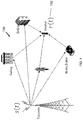
- FIG. 1 shows an example communication network.
- FIG. 2A shows a flowchart of an example wireless communication transmission method.
- FIG. 2B shows a flowchart of an example method of uplink data transmission.
- FIG. 3 shows an example of a wireless transceiver apparatus.
- FIG. 4 shows an example of uplink signal transmissions from multiple user devices to a base station.
- FIG. 5 is a graph showing an example relationship between input and output of an amplifier for linear and non-linear cases.
- FIG. 6 is a graph showing examples of a high peak to average power ratio (PAPR) and a low PAPR waveform.
- PAPR peak to average power ratio
- FIG. 7 graphically illustrates the impact on power efficiency of a communication apparatus due to peaky nature of transmitted waveforms.
- FIG. 8 is a block diagram showing an example of effect of a reflector/interferer in a wireless channel.
- FIG. 9 shows an example of a spectrogram of a wireless communication channel.
- FIG. 10 shows an example of time-frequency assignment of bandwidth to multiple UEs.
- FIG. 11 depicts an example of OTFS modulation system.
- FIG. 12 shows an example of assignment of bandwidth in the delay-Doppler domain to multiple UEs.
- FIG. 13 shows an example of physical resource block (PRB) assignment.
- PRB physical resource block
- FIG. 14 shows an example of uplink resource allocation to a UE.
- FIG. 15 shows an example of uplink resource allocation to a UE.
- FIG. 16 shows comparison between resource allocations in examples of LTE and OTFS based transmission systems.
- FIG. 17 shows an example trajectory of Time Varying Impulse Response for Accelerating Reflector.
- FIG. 18 shows an example of Delay-Doppler Representation for an Accelerating Reflector Channel.
- FIG. 19 depicts example Levels of Abstraction: Signaling over the (i) actual channel with a signaling waveform (ii) the time-frequency Domain (iii) the delay-Doppler Domain.
- FIG. 20 shows examples of notation Used to Denote Signals at Various Stages of Transmitter and Receiver.
- FIG. 21 depicts an example of a conceptual Implementation of the Heisenberg Transform in the Transmitter and the Wigner Transform in the Receiver.
- FIG. 22 shows an example of cross-correlation between g tr (t) and g r (t) for OFDM Systems.
- FIG. 23 shows an example of Information Symbols in the Information (Delay-Doppler) Domain (Right), and Corresponding Basis Functions in the Time-Frequency Domain (Left).
- FIG. 26 depicts an example of a time-Varying Channel Response in the Time-Frequency Domain
- FIG. 27 depicts an example SDFT of Channel response—( ⁇ , ⁇ ) Delay-Doppler Domain.
- FIG. 28 depicts an example SFFT of Channel Response—Sampled ( ⁇ , ⁇ ) Delay-Doppler Domain.
- FIG. 29 depicts an example of Transformation of the Time-Frequency Plane to the Doppler-Delay Plane.
- FIG. 30 depicts an example of a Discrete Impulse in the OTFS Domain Used for Channel Estimation.
- FIG. 31 shows an example of Different Basis Functions, Assigned to Different Users, Span the Whole Time-Frequency Frame.
- FIG. 32 shows an example embodiment of multiplexing three users in the Time-Frequency Domain.
- FIG. 33 shows an example embodiment of Multiplexing three users in the Time-Frequency Domain with Interleaving.
- FIG. 34 shows an example of an OTFS architecture block diagram.
- uplink transmissions In wireless communication systems, transmissions from user equipment (UE) to network are sometimes called uplink transmissions. In some configurations, two UEs may be directly communicating messages with each other and in such configuration, the term “uplink” simply means from one user device to another user device.
- uplink transmissions Various properties of uplink transmissions, including time used, power used, peak to average power ratio (PAPR) of the uplink transmission, etc. can impact both system efficiency, battery life, and also cost of making user equipment electronics.
- PAPR peak to average power ratio
- next generation systems it may be beneficial to provide techniques that improve user equipment design and performance at least in some of the above-described areas.
- the techniques provided in the present document can be used, among other uses, to reduce PAPR of uplink transmissions and also improve bandwidth utilization in the uplink direction.
- FIG. 1 shows an example communication network 100 in which the disclosed technologies can be implemented.
- the network 100 may include a base station transmitter that transmits wireless signals s(t) (downlink signals) to one or more receivers 102 , the received signal being denoted as r(t), which may be located in a variety of locations, including inside or outside a building and in a moving vehicle.
- the receivers may transmit uplink transmissions to the base station, typically located near the wireless transmitter.
- the technology described herein may be implemented at a receiver 102 or at the transmitter (e.g., a base station).
- a wireless cell typically includes a single base station (BS) radio servicing a number of spatially distributed user radios in user equipment (UEs).
- BS base station
- UEs user equipment
- FIG. 4 discloses an example of uplink signal transmissions from multiple user devices to a base station.
- four UEs listed from UE 1 to UE 4 are shown to communication with the base station BS.
- the direction of the UEs transmitting to the BS is called the uplink. Conversely, the direction of the BS transmitting to the UEs is called the downlink.
- the uplink Conversely, the direction of the BS transmitting to the UEs is called the downlink.
- the downlink In this document we disclose an OTFS uplink scheme. Before describing the OTFS uplink scheme we will first give a more detailed description of uplink schemes in general, then discuss metrics for evaluating an uplink scheme, and finally describe LTE's uplink scheme.
- An Uplink user resource allocation scheme is a way of assigning the physical resources of the wireless channel (typically time and frequency) to the different UEs for the uplink transmission.
- the allocation is done in such a way that the BS can subsequently separate the signals transmitted by the different UEs.
- the following aspects may be important when evaluating an uplink scheme: power efficiency and low cost RF components.
- Low cost RF components To keep the cost of the UEs low, it is beneficial to use low cost RF components.
- the UE amplifiers often have severe non-linearity.
- an ideal linear amplifier takes as input a continuous waveform and outputs a waveform which is an amplified version of the input waveform.
- a non-linear amplifier will act like an ideal linear amplifier when the amplitude of the input waveform is small, however, when the amplitude of the input waveform is large the output waveform will have smaller amplitude than desired.
- FIG. 5 is a graph showing an example relationship between input and output of an amplifier for linear and non-linear cases.
- the horizontal axis represents the input power and the vertical axis represents the output power.
- the non-linearity introduced by the amplifier has two negative consequences. One: it broadens the spectrum of the waveform thus potentially causing violations to spectral masks specified by regulators of radio frequency spectrum. Two: it causes non-linear distortion, which raises the noise floor of the transmitted signal. For these reasons, the amplitude of uplink transmissions is typically restricted to the linear regime of the amplifier, with lower output power. The efficiency of the power amplifier decreases when used away from its saturation point. Therefore, it is desirable for the transmit signal to have the smallest possible peak to average power ratio, as further disclosed in this document.
- PAPR Peak to Average Power Ratio
- PAPR ⁇ ( x ) max t ⁇ ( ⁇ x ⁇ ( t ) ⁇ 2 ) mean t ⁇ ( ⁇ x ⁇ ( t ) ⁇ 2 )
- FIG. 6 is a graph showing examples of a high PAPR and a low PAPR waveform. While the term “high” and “low” are relative, in general, it may be desirable to have a PAPR in which waveforms do not swing up or down by more than 6 to 9 dB percent. For high PAPR cases, the peak swings may be 50% or more.
- Standard amplifiers draw a single fixed power supply voltage for the duration of the waveform transmission.
- the voltage drawn is determined by the single largest amplitude peak in the waveform. Whenever the amplitude of the waveform falls below the peak the excess energy drawn by the amplifier is dissipated as heat. This can result in amplifier power efficiencies as low as 10-30%.
- Non-linearity In order to avoid the non-linear region of the power amplifier a waveform with high peaks must be attenuated. This process is called PA back-off and results in a lower energy waveform and hence a lower receiver SNR.
- FIG. 7 graphically illustrates the impact on power efficiency due to a high PAPR signal. Because the supply voltage is provided to accommodates the largest power peaks, when the actual transmitted power is low, the high voltage source may result in producing power that simply gets dissipated out as heat.
- FIG. 8 is a block diagram showing an example of multipath propagation of a wireless signal, causing signal fading.
- signals from the UE reach the BS directly through free air and also by bouncing off reflectors such as a building or a moving car (not shown).
- Data transmitted from the UE radio to the BS radio can take different propagation paths. For transmissions at a fixed frequency the propagated waves can either interfere constructively or destructively at the BS radio. This effect is known as signal fading.
- FIG. 9 illustrates an example of signal fading in real propagation channels over different frequencies.
- the dark spots indicate the time and frequencies which interfere destructively at the BS, causing signal fading.
- the white spots indicate constructive interference, which results in favorable condition for the reception of the signal.
- LTE assigns to each UE a contiguous frequency band to perform single carrier modulation over.
- FIG. 10 shows an example of time-frequency assignment of bandwidth to multiple UEs in 3GPP LTE and NR systems.
- Transmission resources are allocated to three UEs, UE 1 , UE 2 and UE 3 , in terms of different subcarriers (frequencies) along the vertical axis and extending to a time interval (along the horizontal axis).
- the LTE uplink scheme is called Single Carrier Frequency Division Multiple Acces (SC-FDMA).
- SC-FDMA Single Carrier Frequency Division Multiple Acces
- the strength of SC-FDMA is that the uplink waveforms have low PAPR (6-9 dB).
- the weakness of SC-FDMA is that the users are allocated to narrow frequency bands. It is possible for UEs to be assigned to weak portions of the channel, thus limiting uplink data rates.
- OTFS works in the Delay-Doppler coordinate system using a set of basis functions orthogonal to both time and frequency shifts. Both data and reference signals or pilots are carried in this coordinate system.
- the Delay-Doppler domain mirrors the geometry of the wireless channel, which changes far more slowly than the phase changes experienced in the rapidly varying time-frequency domain.
- OTFS symbols are fully spread over time and frequency, taking full advantage of favorable propagation conditions in wireless fading channels.
- FIG. 11 illustrates the modulation and demodulation steps.
- the transmit-side processing is shown on the left, and the receiver-side processing is shown on the right, with channel characteristics in the middle. Additional details are described with reference to FIG. 17 to FIG. 34 .
- the transmit information symbols (QAM symbols) are placed on a lattice or grid in the 2-dimensional Delay-Doppler domain and transformed to the time-frequency domain through a two dimensional Symplectic Fourier Transform. Similar to OFDM (Orthogonal Frequency Division Multiplexing) modulation, the time-frequency plane is organized in sub-carriers and symbols, which form a two-dimensional grid.
- OFDM Orthogonal Frequency Division Multiplexing
- each QAM symbol is spread throughout the Time-Frequency plane (i.e., across the selected signal bandwidth and symbol time) utilizing a different basis function.
- all symbols of the same power have the same SNR and experience exactly the same channel.
- the implication is that, given the appropriate frequency and time observation window, there is no frequency or time selective fading of QAM symbols.
- the transform converts the multiplicative action of the channel into a 2D convolutive interaction with the transmitted QAM symbols.
- OTFS allows for the same OFDM shaping benefits seen in various forms of filtered OFDM. OTFS extracts the full diversity of the channel at the modulation level, allowing the FEC layer to operate on a signal with uniform Gaussian noise pattern, regardless of the particular channel structure.
- the signal is repeated over all symbols in the frame, multiplied by a linear phase.
- the low PAPR property of OTFS is preserved.
- the disclosed OTFS uplink allocation scheme assigns the UEs to disjoint Doppler slices of the delay-Doppler torus.
- FIG. 12 shows an example of assignment of bandwidth in the delay-Doppler domain to multiple UEs. Resources may allocated to UEs UE 1 , UE 2 and UE 3 sequentially starting from a slice in the delay ( ⁇ ) domain, and continuing to another Doppler domain ( ⁇ ) value and so on.
- each UE is allocated resources along delay dimensions, using a single Doppler dimension.
- more than one Doppler dimension may be allocated if more resources are needed by one UE.
- This type of resource allocation may also be described as Delay first symbol mapping.
- FIG. 12 shows an illustration of proposed embodiment, where each UE is allocated resources along the Delay dimensions, using one or more than one Doppler dimensions. It may also be referred to as Delay first mapping.
- resources are organized in physical resource blocks (PRB), containing a fixed number of symbols, for the purpose of scheduling and channel coding.
- PRB physical resource blocks
- no PRB are defined, and allocations are performed with Delay first mapping for an arbitrary number of symbols.
- PRB are defined along one Doppler dimension, having a fixed number of symbols.
- the number of symbols in one PRB may vary due to the insertion of reference symbols, control signaling, blank symbols, or other aspects necessary for the transmission.
- PRB are defined along one Doppler dimension, having a variable number of symbols, with the number of PRB contained by one Doppler dimension being fixed.
- a PRB may contain all symbols (i.e. all Delay dimensions) in a fixed number (e.g. one) of Doppler dimensions.
- FIG. 13 provides an illustration of PRB definition along Delay domain.
- system parameters may be defined:
- Sub-carrier spacing 15 kHz
- the OTFS delay-Doppler grid consists of 1200 delay bins (dimensions) and 14 Doppler bins (dimensions).
- 1200 delay bins dimensions
- 14 Doppler bins dimensions.
- the parameters described take the values specified by 3GPP for LTE and for NR, respectively. In other embodiments, different values for the parameters described in Table 2 are used.
- the UEs To modulate data the UEs first places a sequence of QAMs on their assigned resource elements, in the region of the delay-Doppler plane corresponding to their PRB (physical resource block) allocation. Next, the UEs perform an OTFS transform to convert their data from delay-Doppler to time-frequency. Finally, the standard OFDM zero-padded IFFT generates a time series.
- PRB physical resource block
- the disclosed uplink has two key benefits:
- the PAPR of the time series is low (equivalent to single carrier SC-FDMA modulation).
- FIG. 14 shows an example of uplink resource allocation to a UE.
- each QAM is transformed to a constant amplitude wave across the time dimension. No new peaks are added to the data (Note that this may no longer true for larger packets which cover multiple Doppler slices).
- N ⁇ -FFT followed by the zero padded N f -IFFT is exactly SC-FDMA and so produces a low PAPR time series.
- FIG. 15 shows another example of uplink resource allocation to a UE.
- FIG. 16 illustrates resource allocation in OTFS communication, compared to the traditional OFDM based systems such as a Long Term Evolution system.
- the OTFS modulation spreads each QAM symbol of the full bandwidth and TTI duration and so achieves the full diversity of the channel.
- SC-FDMA modulation only transmits over a narrow bandwidth.
- the proposed resource allocation scheme for OTFS has therefore distinct advantages over the most widely used wireless modulation schemes, namely OFDM and SC-FDMA:
- the OTFS uplink scheme maintains the low PAPR or SC-FDMA for small packet size while at the same time spreading UE data over the full time frequency plane thus extracting the full diversity of the channel.
- the scheduler can take advantage of the flexibility afforded by the uplink scheme:
- Described herein are methods for allocation of transmission resources to uplink data transmissions.
- FIG. 2A is a flowchart for an example method 200 for allocating transmission resources to uplink transmission from a user equipment are disclosed.
- the technique includes performing the following operations: dividing ( 202 ) transmission resources into a two-dimensional grid of resource elements defined by a delay dimension and a Doppler dimension that is orthogonal to the delay dimension, assigning ( 204 ), to an uplink transmission from a user equipment, a set of resource elements, mapping ( 206 ) data symbols of the uplink transmission to the set of resource elements, performing ( 208 ) an orthogonal time frequency space (OTFS) transform on the mapped set of resource elements into a time-frequency representation; and processing and transmitting ( 210 ) the time-frequency domain signal.
- OTFS orthogonal time frequency space
- the set of resource elements comprises a Doppler slice that includes all resource elements having a same value along the Doppler dimension.
- the OTFS transform of the mapped set of resource elements results in the time-frequency representation being spread across an entire frequency band.
- the assigning ( 204 ) may include assigning, to the user equipment, a set of resources comprising all resources along the delay dimension for one or more Doppler dimension values in a logical group of resources.
- the logical group of resources includes one or more physical resource blocks (PRBs).
- PRBs physical resource blocks
- a PRB may include a number of symbols along one Doppler value.
- the logical group of resources includes a number of transmission symbols.
- the set of resources in the delay-Doppler domain assigned to uplink data transmission of each user equipment are non-overlapping, and wherein the time-frequency domain signal for at least some of the user equipment are overlapping in time/and or frequency dimension.
- FIG. 2B is a flowchart for an example method 250 of reducing peak to average power ratio of an uplink transmission from a user equipment is disclosed.
- the method 250 includes dividing ( 252 ) transmission resources into a two-dimensional grid of resource elements defined by a delay dimension and a Doppler dimension that is orthogonal to the delay dimension, assigning ( 252 ), to an uplink transmission from a user equipment, a set of resource elements, wherein the set of resource elements have a single Doppler value along the Doppler dimension, mapping ( 256 ) data symbols of the uplink transmission to the set of resource elements, performing ( 258 ) an orthogonal time frequency space (OTFS) transform on the mapped set of resource elements into a time-frequency representation, and processing and transmitting ( 260 ) the time-frequency domain signal.
- OTFS orthogonal time frequency space
- the processing the time-frequency domain signal includes zero-padding and generating a time series of symbols for transmission.
- the set of resource elements are logically divided into a number of physical resource blocks (PRBs), wherein, for example, each PRB includes a number of symbols along the single Doppler value.
- PRBs physical resource blocks
- a method may be implemented by a signal reception apparatus (e.g., base station) in which the uplink transmissions scheduled according to any of the above-described techniques are transmitted by the UEs.
- a signal reception apparatus e.g., base station
- FIG. 3 shows an example of a wireless transceiver apparatus 300 .
- the apparatus 300 may be used to implement method 200 .
- the apparatus 300 includes a processor 302 , a memory 304 that stores processor-executable instructions and data during computations performed by the processor.
- the apparatus 300 includes reception and/or transmission circuitry 306 , e.g., including radio frequency operations for receiving or transmitting signal and/or receiving data or information bits for transmission over a wireless network.
- 4G wireless networks have served the public well, providing ubiquitous access to the internet and enabling the explosion of mobile apps, smartphones and sophisticated data intensive applications like mobile video. This continues an honorable tradition in the evolution of cellular technologies, where each new generation brings enormous benefits to the public, enabling astonishing gains in productivity, convenience, and quality of life.
- the spectral efficiency for short bursts will have to be improved, as well as the energy consumption of these devices (allowing for 10 years operation on the equivalent of 2 AA batteries).
- the network synchronization requirements place a burden on the devices to be almost continuously on.
- the efficiency goes down as the utilization per UE (user equipment, or mobile device) goes down.
- the PHY requirements for strict synchronization between UE and eNB Evolved Node B, or LTE base station
- CIoT cellular IoT
- 5G CIoT solutions should be able to coexist with the traditional high-throughput applications by dynamically adjusting parameters based on application context.
- OTFS is a modulation technique that modulates each information (e.g., QAM) symbol onto one of a set of two dimensional (2D) orthogonal basis functions that span the bandwidth and time duration of the transmission burst or packet.
- the modulation basis function set is specifically derived to best represent the dynamics of the time varying multipath channel.
- OTFS transforms the time-varying multipath channel into a time invariant delay-Doppler two dimensional convolution channel. In this way, it eliminates the difficulties in tracking time-varying fading, for example in high speed vehicle communications.
- OTFS increases the coherence time of the channel by orders of magnitude. It simplifies signaling over the channel using well studied AWGN codes over the average channel SNR. More importantly, it enables linear scaling of throughput with the number of antennas in moving vehicle applications due to the inherently accurate and efficient estimation of channel state information (CSI). In addition, since the delay-doppler channel representation is very compact, OTFS enables massive MIMO and beamforming with CSI at the transmitter for four, eight, and more antennas in moving vehicle applications. The CSI information needed in OTFS is a fraction of what is needed to track a time varying channel.
- one QAM symbol may be spread over multiple time and/or frequency points. This is a key technique to increase processing gain and in building penetration capabilities for CIoT deployment and PSTN replacement applications. Spreading in the OTFS domain allows spreading over wider bandwidth and time durations while maintaining a stationary channel that does not need to be tracked over time.
- CoMP and network MIMO techniques have stringent clock synchronization requirements for the cooperating eNBs. If clock frequencies are not well synchronized, the UE will receive each signal from each eNB with an apparent “Doppler” shift. OTFS's reliable signaling over severe Doppler channels can enable CoMP deployments while minimizing the associated synchronization difficulties.
- Section 2 we start by describing the wireless Doppler multipath channel and its effects on multicarrier modulation.
- the (time-varying) channel response is sampled over points of the time-frequency plane.
- Sections 5 and 6 we explore aspects of channel estimation in the new information domain and multiplexing multiple users respectively, while in Section 7 we address complexity and implementation issues.
- Sections 8 we provide some performance results and we put the OTFS modulation in the context of cellular systems, discuss its attributes and its benefits for 5G systems.
- the received signal is a superposition of reflected copies of the transmitted signal, where each copy is delayed by the path delay ⁇ , frequency shifted by the Doppler shift ⁇ and weighted by the time-invariant delay-Doppler impulse response h( ⁇ , ⁇ ) for that ⁇ and ⁇ .
- FIG. 17 shows the time-varying impulse response for an accelerating reflector in the ( ⁇ , t) coordinate system
- FIG. 18 shows the same channel represented as a time invariant impulse response in the ( ⁇ , ⁇ ) coordinate system.
- FIGS. 1 and 2 An important feature revealed by these two FIGS. is how compact the ( ⁇ , ⁇ ) representation is compared to the ( ⁇ , t) representation. This has important implications for channel estimation, equalization and tracking as will be discussed later.
- weights x( ⁇ , ⁇ ) represent the information bearing signal to be transmitted.
- Eq. (2) reduces to a time invariant convolution.
- the impulse response is parameterized by one dimension, in the time varying case we have a two dimensional impulse response.
- the convolution operator produces a superposition of delays of the input s(t), (hence the parameterization is along the one dimensional delay axis) in the time varying case we have a superposition of delay-and-modulate operations as seen in Eq.
- Eq. (7) The important point of Eq. (7) is that the operator ⁇ h (•) can be compactly parameterized in a two dimensional space h( ⁇ , ⁇ ), providing an efficient, time invariant description of the channel. Typical channel delay spreads and Doppler spreads are a very small fraction of the symbol duration and subcarrier spacing of multicarrier systems.
- the time variation of the channel introduces significant difficulties in wireless communications related to channel acquisition, tracking, equalization and transmission of channel state information (CSI) to the transmit side for beamforming and MIMO processing.
- CSI channel state information
- the channel coherence time is increased by orders of magnitude and the issues associated with channel fading in the time or frequency domain in SISO or MIMO systems are significantly reduced.
- Orthogonal Time Frequency Space (OTFS) modulation is comprised of a cascade of two transformations.
- the first transformation maps the two dimensional plane where the information symbols reside (and which we call the delay-Doppler plane) to the time frequency plane.
- the second one transforms the time frequency domain to the waveform time domain where actual transmitted signal is constructed. This transform can be thought of as a generalization of multicarrier modulation schemes.
- FIG. 19 provides a pictorial view of the two transformations that constitute the OTFS modulation. It shows at a high level the signal processing steps that are required at the transmitter and receiver. It also includes the parameters that define each step, which will become apparent as we further expose each step. Further, FIG. 20 shows a block diagram of the different processing stages at the transmitter and receiver and establishes the notation that will be used for the various signals.
- the channel is orthogonalized on the time-frequency grid.
- the channel time variation is simplified on the time-frequency grid and can be addressed with an additional transform.
- a lattice or grid on the time frequency plane that is a sampling of the time axis with sampling period T and the frequency axis with sampling period ⁇ f.
- ⁇ ⁇ ( nT,m ⁇ f ), n,m ⁇ ⁇ (8)
- the time-frequency modulator is a Heisenberg operator on the lattice ⁇ , that is, it maps the two dimensional symbols X[n. m] to a transmitted waveform, via a superposition of delay-and-modulate operations on the pulse waveform g tr (t) 2
- This orthogonality property is required if the receiver uses the same pulse as the transmitter. We will generalize it to a bi-orthogonality property in later sections.
- the sampling rate in the time-frequency domain is related to the bandwidth and time duration of the pulse g tr (t) namely its time-frequency localization.
- the time spacing In order for the orthogonality condition of (9) to hold for a frequency spacing ⁇ f, the time spacing must be T ⁇ 1/M.
- This result can be considered an extension of the single carrier modulation case, where the received signal through a time invariant channel is given by the convolution of the QAM symbols with a composite pulse, that pulse being the convolution of the transmitter pulse and the channel impulse response.
- Typical communication system design dictates that the receiver performs a matched filtering operation, taking the inner product of the received waveform with the transmitter pulse, appropriately delayed or otherwise distorted by the channel.
- FIG. 21 provides a conceptual view of this processing.
- On the transmitter we modulate a set of M subcarriers for each symbol we transmit, while on the receiver we perform matched filtering on each of those subcarrier pulses.
- the receiver pulse g r (t) is in many cases identical to the transmitter pulse, but we keep the separate notation to cover some cases where it is not (most notably in OFDM where the CP samples have to be discarded).
- the sufficient statistics for symbol detection are obtained by matched filtering with the channel-distorted, information-carrying pulses (assuming that the additive noise is white and Gaussian).
- the channel distorted version of each subcarrier signal is only a scalar version of the transmitted signal, allowing for a matched filter design that is independent of the channel and uses the original transmitted subcarrier pulse. We will make these statements more precise shortly and examine the required conditions for this to be true.
- FIG. 21 is only a conceptual illustration and does not point to the actual implementation of the receiver.
- this matched filtering is implemented in the digital domain using an FFT or a polyphase transform for OFDM and MCFB respectively.
- FFT Fast Fourier transform
- MCFB Polyphase transform
- the ambiguity function is related to the inverse of the Heisenberg transform, namely the Wigner transform.
- FIG. 21 provides an intuitive feel for that, as the receiver appears to invert the operations of the transmitter4. 4 More formally, if we take the cross-ambiguity or the transmit and receive pulses A g r ,g tr ( ⁇ , ⁇ ), and use it as the impulse response of the Heisenberg operator, then we obtain the orthogonal cross-projection operator
- V( ⁇ , ⁇ ) A g r , v ( ⁇ , ⁇ ).
- the first term on the right hand side is the matched filter output to the (noiseless) input comprising of a superposition of delayed and modulated versions of the transmit pulse.
- this term can be expressed as the twisted convolution of the two dimensional impulse response f( ⁇ , ⁇ ) with the cross-ambiguity function (or two dimensional cross correlation) of the transmit and receive pulses.
- V( ⁇ , ⁇ ) is the additive noise term.
- Eq. (24) provides an abstraction of the time varying channel on the time-frequency plane. It states that the matched filter output at any time and frequency point ( ⁇ , ⁇ ) is given by the delay-Doppler impulse response of the channel twist-convolved with the impulse response of the modulation operator twist-convolved with the cross-ambiguity (or two dimensional cross correlation) function of the transmit and receive pulses.
- V[n, m] is the additive white noise.
- Eq. (28) shows that the matched filter output does recover the transmitted symbols (plus noise) under ideal channel conditions.
- the channel orthogonalization is maintained (no intersymbol or intercarrier interference), while the channel complex gain distortion has a closed form expression.
- Eq. (29) is a fundamental equation that describes the channel behavior in the time-frequency domain. It is the basis for understanding the nature of the channel and its variations along the time and frequency dimensions.
- the end-to-end channel distortion in the modulation domain is a (complex) scalar that needs to be equalized
- each subcarrier symbol is multiplied by the frequency response of the time invariant channel evaluated at the frequency of that subcarrier.
- FIG. 22 shows the cross correlation between the transmit and receive pulses of (13) and (32). Notice that the cross correlation is exactly equal to one and zero in the vicinity of zero and ⁇ T respectively, while holding those values for the duration of T CP . Hence, as long as the support of the channel on the time dimension is less than T CP the bi-orthogonality condition is satisfied along the time dimension. Across the frequency dimension the condition is only approximate, as the ambiguity takes the form of a sinc function as a function of frequency and the nulls are not identically zero for the whole support of the Doppler spread.
- time-frequency response H[n, m] in (29) is related to the channel delay-Doppler response h( ⁇ , ⁇ ) by an expression that resembles a Fourier transform.
- the transform is two dimensional (along delay and Doppler) and (ii) the exponentials defining the transforms for the two dimensions have opposing signs.
- Eq. (29) points in the direction of using complex exponentials as basis functions on which to modulate the information symbols; and only transmit on the time-frequency domain the superposition of those modulated complex exponential bases. This is the approach we will pursue in this section.
- x( ⁇ , ⁇ ) is periodic with periods (1/ ⁇ f, 1/T).
- This transform defines a new two dimensional plane, which we will call the delay-Doppler plane, and which can represent a max delay of 1/ ⁇ f and a max Doppler of 1/T.
- a one dimensional periodic function is also called a function on a circle, while a 2D periodic function is called a function on a torus (or donut).
- x( ⁇ , ⁇ ) is defined on a torus Z with circumferences (dimensions) (1/ ⁇ f, 1/T).
- the periodicity of x( ⁇ , ⁇ ) (or sampling rate of the time-frequency plane) also defines a lattice on the delay-Doppler plane, which we will call the reciprocal lattice
- ⁇ ⁇ ⁇ ( m ⁇ 1 ⁇ ⁇ ⁇ f , n ⁇ 1 T ) , n , m ⁇ Z ⁇ ( 34 )
- the points on the reciprocal lattice have the property of making the exponent in (33), an integer multiple of 2 ⁇ .
- ⁇ 0 ⁇ ⁇ ( m ⁇ 1 M ⁇ ⁇ ⁇ ⁇ ⁇ f , n ⁇ 1 NT ) , n , m ⁇ Z ⁇ ( 36 )
- x p [m, n] is also periodic with period [M, N] or equivalently, it is defined on the discrete torus Z 0 ⁇ .
- the SFFT(X[n, m]) is a linear transformation from (Z 0 ) ⁇ (Z 0 ⁇ ).
- the SDFT is called “discrete” because it represents a signal using a discrete set of exponentials
- the SFFT is called “finite” because it represents a signal using a finite set of exponentials.
- a lattice on the time frequency plane that is a sampling of the time axis with sampling period T and the frequency axis with sampling period ⁇ f (c.f. Eq. (8)).
- the first equation in (44) describes the OTFS transform, which combines an inverse symplectic transform with a widowing operation.
- the second equation describes the transmission of the modulation symbols X[n, m] via a Heisenberg transform of g tr (t) parameterized by X[n, m]. More explicit formulas for the modulation steps are given by Equations (41) and (10).
- FIG. 23 visualizes this interpretation by isolating each symbol in the information domain and showing its contribution to the time-frequency modulation domain.
- the transmitted signal is the superposition of all the symbols on the right (in the information domain) or all the basis functions on the left (in the modulation domain).
- SFFT ⁇ 1 (x[k, l]) is a periodic sequence that extends to infinite time and bandwidth.
- the window in general could extend beyond the period of the information symbols [M, N] and could have a shape different from a rectangular pulse. This would be akin to adding cyclic prefix/suffix in the dimensions of both time and frequency with or without shaping.
- the choice of window has implications on the shape and resolution of the channel response in the information domain as we will discuss later. It also has implications on the receiver processing as the potential cyclic prefix/suffix has to either be removed or otherwise handled as we see next.
- the first step of the demodulation operation can be interpreted as a matched filtering operation on the time-frequency domain as we discussed earlier.
- the second step is there to ensure that the input to the SFFT is a periodic sequence. If the trivial window is used, this step can be skipped.
- the third step can also be interpreted as a projection of the time-frequency modulation symbols on the orthogonal basis functions
- the discrete OTFS modulation defined above points to efficient implementation via discrete-and-periodic FFT type processing. However, it does not provide insight into the time and bandwidth resolution of these operations in the context of two dimensional Fourier sampling theory.
- a lattice on the time frequency plane that is a sampling of the time axis with sampling period T and the frequency axis with sampling period ⁇ f (c.f. Eq. (8)).
- the first equation describes the inverse discrete time-frequency symplectic Fourier transform [c.f. Eq. (35)] and the windowing function, while the second equation describes the transmission of the modulation symbols via a Heisenberg transform [c.f. Eq. (10)].
- the main result in this section shows how the time varying channel in (2), (7), is transformed to a time invariant convolution channel in the delay Doppler domain.
- Proposition 3 Consider a set of NM QAM information symbols arranged in a 2D periodic sequence x[l, k] with period [M, N]. The sequence x[k, l] undergoes the following transformations:
- h w ⁇ ( l - m M ⁇ ⁇ ⁇ ⁇ ⁇ f , k - n NT ) h w ⁇ ( ⁇ ′ , v ′ ) ⁇
- h w ( ⁇ ′, ⁇ ′) denotes the circular convolution of the channel response with a windowing function5
- h w ( ⁇ ′, ⁇ ′) ⁇ e ⁇ j2 ⁇ h ( ⁇ , ⁇ ) w ( ⁇ ′ ⁇ , ⁇ ′ ⁇ ) d ⁇ d ⁇ (54)
- windowing function w( ⁇ , ⁇ ) is the symplectic Fourier transform of the time-frequency window W[n, m]
- W[n, m] is the product of the transmit and receive window.
- W [ n,m ] W tr [ n,m ] W r [ n,m ] (56) 5
- w( ⁇ , ⁇ ) is circularly convolved with a slightly modified version of the channel impulse response e ⁇ j2 ⁇ h( ⁇ , ⁇ ) (by a complex exponential) as can be seen in the equation.
- the window effect is to produce a blurred version of the original channel with a resolution that depends on the span of the frequency and time samples available as will be discussed in the next section.
- the system can be designed with a window function aimed at randomizing the phases of the transmitted symbols, akin to how QAM symbol phases are randomized in WiFi and Multimedia-Over-Coax communication systems. This randomization may be more important for pilot symbols than data carrying symbols. For example, if neighboring cells use different window functions, the problem of pilot contamination is avoided.
- a different use of the window is the ability to implement random access systems over OTFS using spread spectrum/CDMA type techniques as will be discussed later.
- OTFS transforms the time-frequency domain to the delay-Doppler domain creating the Fourier pairs: (i) time ⁇ Doppler and (ii) frequency ⁇ delay.
- the “spectral” resolution of interest here therefore is either on the Doppler or on the delay dimensions.
- the delay dimension of the SDFT is periodic with period 1/ ⁇ f as expected due to the nature of the discrete Fourier transform.
- the reflectors are separated by more than 1/M ⁇ f and are resolvable. If they were not, then the system would experience a flat channel within the bandwidth of observation, and in the delay domain the two reflectors would have been blurred into one.
- FIG. 25 shows similar results for a flat Doppler channel with time varying frequency response H(0, t) for all f.
- the first plot shows the the response as a function of time, while the second plot shown the SDFT along the Doppler dimension.
- the third plot shows the SFFT, that is the sampled version of the transform. Notice that the SDFT is periodic with period 1/T while the SFFT is periodic with period 1/T and has resolution of 1/NT.
- OTFS can take a channel that inherently has a coherence time of only T and produce an equivalent channel in the delay Doppler domain that has coherence time NT. This is an important property of OTFS as it can increase the coherence time of the channel by orders of magnitude and enable MIMO processing and beamforming under Doppler channel conditions.
- the two one-dimensional channel examples we have examined are special cases of the more general two-dimensional channel of FIG. 26 .
- the time-frequency response and its sampled version are shown in this figure, where the sampling period is (T, ⁇ f).
- FIG. 27 shows the SDFT of this sampled response which is periodic with period (1/T, 1/ ⁇ f), across the Doppler and delay dimensions respectively.
- FIG. 28 shows the SFFT, that is, the sampled version of FIG. 27 .
- the resolution of FIG. 27 is 1/NT, 1/M ⁇ f across the Doppler and delay dimensions respectively.
- the OTFS modulation consists of two steps shown in this figure:
- a Heisenberg transform translates a time-varying convolution channel in the waveform domain to an orthogonal but still time varying channel in the time frequency domain.
- a SFFT transform translates the time-varying channel in the time-frequency domain to a time invariant one in the delay-Doppler domain.
- the Doppler resolution is 1/T f and the delay resolution is 1/BW.
- the choice of window can provide a tradeoff between main lobe width (resolution) and side lobe suppression, as in classical spectral analysis.
- a straightforward way to perform channel estimation entails transmitting a sounding OTFS frame containing a discrete delta function in the OTFS domain or equivalently a set of unmodulated carriers in the time frequency domain.
- the carriers may be modulated with known, say BPSK, symbols which are removed at the receiver as is common in many OFDM systems.
- This approach could be considered an extension of the channel estimation symbols used in WiFi and Multimedia-Over-Coax modems.
- FIG. 30 shows an OTFS symbol containing such an impulse.
- channel estimation symbols are limited to a small part of the OTFS frame, they actually sound the whole time-frequency domain via the corresponding basis functions associated with these symbols.
- a different approach to channel estimation is to devote pilot symbols on a subgrid in the time-frequency domain. This is akin to CRS pilots in downlink LTE subframes.
- the key question in this approach is the determination of the density of pilots that is sufficient for channel estimation without introducing aliasing. Assume that the pilots occupy the subgrid (n 0 T, m 0 ⁇ f) for some integers n 0 , m 0 . Recall that for this grid the SDFT will be periodic with period (1/n 0 T, 1/m 0 ⁇ f).
- Multiplexing in the delay-Doppler domain This is the most natural multiplexing scheme for downlink transmissions. Different sets of OTFS basis functions, or sets of information symbols or resource blocks are given to different users. Given the orthogonality of the basis functions, the users can be separated at the UE receiver. The UE need only demodulate the portion of the OTFS frame that is assigned to it.
- FIG. 31 illustrates this point by showing two different basis functions belonging to different users. Because of this, there is no compromise on channel resolution for each user, regardless of the resource block or subframe size.
- FIG. 32 illustrates this for a three user case.
- User 1 blue, 1602
- Users 2 and 3 red, 1604 , and black, 1606 , respectively
- occupy the other half subcarriers and divide the total length of the frame between them.
- each user employs a slightly different version of the OTFS modulation described in Section 3.
- One difference is that each user i performs an SFFT on a subframe (N i , M i ), N i ⁇ N, M i ⁇ M. This reduces the resolution of the channel, or in other words reduces the extent of the time-frequency plane in which each user will experience its channel variation. On the other side, this also gives the scheduler the opportunity to schedule users in parts of the time-frequency plane where their channel is best.
- FIG. 33 shows the same three users as before but interleaved on the subcarrier dimension ( 1702 , 1704 and 1706 respectively).
- interleaving is possible in the time dimension as well, and/or in both dimensions.
- the degree of interleaving, or subsampling the grip per user is only limited by the spread of the channel that we need to handle.
- OTFS can support such a system by employing a spread-spectrum approach.
- Each user is assigned a different two-dimensional window function that is designed as a randomizer.
- the windows of different users are designed to be nearly orthogonal to each other and nearly orthogonal to time and frequency shifts.
- Each user then only transmits on one or a few basis functions and uses the window as a means to randomize interference and provide processing gain. This can result in a much simplified system that may be attractive for low cost, short burst type of IoT applications.
- a multi-antenna OTFS system can support multiple users transmitting on the same basis functions across the whole time-frequency frame.
- the users are separated by appropriate transmitter and receiver beamforming operations.
- a detailed treatment of MIMO-OTFS architectures however is outside the scope of this paper.
- OTFS is a novel modulation technique with numerous benefits and a strong mathematical foundation. From an implementation standpoint, its added benefit is the compatibility with OFDM and the need for only incremental change in the transmitter and receiver architecture.
- OTFS consists of two steps.
- the Heisenberg transform (which takes the time-frequency domain to the waveform domain) is already implemented in today's systems in the form of OFDM/OFDMA. In the formulation of this paper, this corresponds to a prototype filter g(t) which is a square pulse.
- Other filtered OFDM and filter bank variations have been proposed for 5G, which can also be accommodated in this general framework with different choices of g(t).
- the second step of OTFS is the two dimensional Fourier transform (SFFT). This can be thought of as a pre- and post-processing step at the transmitter and receiver respectively as illustrated in FIG. 34 . In that sense it is similar, from an implementation standpoint, to the SC-FDMA pre-processing step.
- SFFT two dimensional Fourier transform
- OTFS augments the PHY capabilities of an existing LTE modem architecture and does not introduce co-existence and compatibility issues.
- the OTFS modulation has numerous benefits that tie into the challenges that 5G systems are trying to overcome.
- the biggest benefit and the main reason to study this modulation is its ability to communicate over a channel that randomly fades within the time-frequency frame and still provide a stationary, deterministic and non-fading channel interaction between the transmitter and the receiver.
- all information symbols experience the same channel and same SNR.
- OTFS best utilizes the fades and power fluctuations in the received signal to maximize capacity.
- the channel consists of two reflectors which introduce peaks and valleys in the channel response either across time or across frequency or both.
- An OFDM system can theoretically address this problem by allocating power resources according to the waterfilling principle.
- An OTFS system would resolve the two reflectors and the receiver equalizer would employ coherent combining of the energy of the two reflectors, providing a non-fading channel with the same SNR for each symbol. It therefore provides a channel interaction that is designed to maximize capacity under the transmit assumption of equal power allocation across symbols (which is common in existing wireless systems), using only standard AWGN codes.
- OTFS provides a domain in which the channel can be characterized in a very compact form. This has significant implications for addressing the channel estimation bottlenecks that plague current multi-antenna systems and can be a key enabling technology for addressing similar problems in future massive MIMO systems.
- OTFS One benefit of OTFS is its ability to easily handle extreme Doppler channels.
- OTFS provides a natural way to apply spreading codes and deliver processing gain, and spread-spectrum based CDMA random access to multicarrier systems. It eliminates the time and frequency fades common to multicarrier systems and simplifies the receiver maximal ratio combining subsystem.
- the processing gain can address the challenge of deep building penetration needed for IoT and PSTN replacement applications, while the CDMA multiple access scheme can address the battery life challenges and short burst efficiency needed for IOT deployments.
- the compact channel estimation process that OTFS provides can be essential to the successful deployment of advanced technologies like Cooperative Multipoint (Co-MP) and distributed interference mitigation or network MIMO.
- Co-MP Cooperative Multipoint
- network MIMO distributed interference mitigation
- SFFT ⁇ ( X 2 ⁇ [ n - k , m - l ] ) SFFT ⁇ ( X 2 ⁇ [ n , m ] ) ⁇ e - j ⁇ ⁇ 2 ⁇ ⁇ ⁇ ( nK N - ml M ) ( 64 )
- Appendix B discloses certain useful aspects of OTFS modulation techniques.
- the disclosed and other embodiments, modules and the functional operations described in this document can be implemented in digital electronic circuitry, or in computer software, firmware, or hardware, including the structures disclosed in this document and their structural equivalents, or in combinations of one or more of them.
- the disclosed and other embodiments can be implemented as one or more computer program products, i.e., one or more modules of computer program instructions encoded on a computer readable medium for execution by, or to control the operation of, data processing apparatus.
- the computer readable medium can be a machine-readable storage device, a machine-readable storage substrate, a memory device, a composition of matter effecting a machine-readable propagated signal, or a combination of one or more them.
- data processing apparatus encompasses all apparatus, devices, and machines for processing data, including by way of example a programmable processor, a computer, or multiple processors or computers.
- the apparatus can include, in addition to hardware, code that creates an execution environment for the computer program in question, e.g., code that constitutes processor firmware, a protocol stack, a database management system, an operating system, or a combination of one or more of them.
- a propagated signal is an artificially generated signal, e.g., a machine-generated electrical, optical, or electromagnetic signal, that is generated to encode information for transmission to suitable receiver apparatus.
- a computer program (also known as a program, software, software application, script, or code) can be written in any form of programming language, including compiled or interpreted languages, and it can be deployed in any form, including as a standalone program or as a module, component, subroutine, or other unit suitable for use in a computing environment.
- a computer program does not necessarily correspond to a file in a file system.
- a program can be stored in a portion of a file that holds other programs or data (e.g., one or more scripts stored in a markup language document), in a single file dedicated to the program in question, or in multiple coordinated files (e.g., files that store one or more modules, sub programs, or portions of code).
- a computer program can be deployed to be executed on one computer or on multiple computers that are located at one site or distributed across multiple sites and interconnected by a communication network.
- the processes and logic flows described in this document can be performed by one or more programmable processors executing one or more computer programs to perform functions by operating on input data and generating output.
- the processes and logic flows can also be performed by, and apparatus can also be implemented as, special purpose logic circuitry, e.g., an FPGA (field programmable gate array) or an ASIC (application specific integrated circuit).
- processors suitable for the execution of a computer program include, by way of example, both general and special purpose microprocessors, and any one or more processors of any kind of digital computer.
- a processor will receive instructions and data from a read only memory or a random access memory or both.
- the essential elements of a computer are a processor for performing instructions and one or more memory devices for storing instructions and data.
- a computer will also include, or be operatively coupled to receive data from or transfer data to, or both, one or more mass storage devices for storing data, e.g., magnetic, magneto optical disks, or optical disks.
- mass storage devices for storing data, e.g., magnetic, magneto optical disks, or optical disks.
- a computer need not have such devices.
- Computer readable media suitable for storing computer program instructions and data include all forms of non-volatile memory, media and memory devices, including by way of example semiconductor memory devices, e.g., EPROM, EEPROM, and flash memory devices; magnetic disks, e.g., internal hard disks or removable disks; magneto optical disks; and CD ROM and DVD-ROM disks.
- semiconductor memory devices e.g., EPROM, EEPROM, and flash memory devices
- magnetic disks e.g., internal hard disks or removable disks
- magneto optical disks e.g., CD ROM and DVD-ROM disks.
- the processor and the memory can be supplemented by, or incorporated in, special purpose logic circuitry.
Landscapes
- Engineering & Computer Science (AREA)
- Signal Processing (AREA)
- Computer Networks & Wireless Communication (AREA)
- Physics & Mathematics (AREA)
- Discrete Mathematics (AREA)
- General Physics & Mathematics (AREA)
- Mathematical Physics (AREA)
- Mobile Radio Communication Systems (AREA)
Abstract
Description
| TABLE 1 | |
| Parameter | |
| System Bandwidth |
| 5 |
10 |
20 MHz |
| |
1 ms |
| Sub-carrier spacing | 15 kHz |
| Number of OTFS | 14 |
| symbols per frame | |||
| Number of |
300 | 600 | 1200 |
| |
100 |
| Number of PRB ( |
3 | 6 | 12 |
| 1) per Doppler | |||
| |
| PRB size |
| 2 | 150 |
| Number of PRB ( |
2 | 4 | 8 |
| 2) per Doppler | |||
| dimension | |||
| TABLE 2 | |
| Parameter | |
| System Bandwidth |
| 5 |
10 |
20 MHz |
| OTFS frame duration | 0.5 ms |
| Sub-carrier spacing | 30 kHz |
| Number of OTFS | 14 |
| symbols per frame |
| Number of sub-carriers | 150 | 300 | 600 |
| |
150 |
| Number of PRB ( |
2 | 4 | 8 |
| 2) per Doppler | |||
| dimension | |||
r(t)=∫
r(t)=∫∫h(τ,ν)e j2πν(t−τ) s(t−τ)dνdτ (2)
ϕτ,ν(t−τ 0)=ϕτ+τ
e j2πν
s(t)=∫∫x(τ,ν)ϕτ,ν(t)dτdν (5)
Λ={(nT,mΔf),n,m ∈
s(t)=Σn=0 N−1 X[n]g(t−nT) (12)
x(t)=Σm=−M/2 M/2−1 X[n,m]g tr(t)d j2πmΔft (14)
3Technically, the pulse of Eq. (13) is not orthonormal but is orthogonal to the receive filter (where the CP samples are discarded) as we will see shortly.
Πh
h(τ,ν)=∫∫h 2(τ′,ν′)h 1(τ−τ′,ν−ν′)e j2πν′(τ−τ′)t dτ′dντ (16)
r(t)=Πf(g tr(t))+v(t)=∫∫f(τ,ν)e j2πν(t−τ) g tr(t−τ)dνdτ+ (17)
f(τ,ν)=h(τν)⊙X[n,m]=Σm=−M/2 M/2−1Σn=0 N−1 X[n,m]h(τ−nT,ν−mΔf)e j2π(ν−mΔf)nT (18)
A g
Y[n,m]=A g
In words, the coefficients that come out of the matched filter, if used in a Heisenberg representation, will provide the best approximation to the original y(t) in the sense of minimum square error.
Y(τ,ν)=A g
Πf(g tr(t))=∫∫f(τ,ν)e j2πν(t−τ) g tr(t−τ)dνdτ (22)
A g
{circumflex over (X)}[m,n]=Y[n,m]=Y(τ,ν)|τ=nT,ν=mΔf (2)
Y[n,m]=X[n,m]+V[n,m] (28)
Y[n,m]=H[n,m]X[n,m]H[n,m]=∫∫h(τ,ν)e j2πνnT e −j2π(ν+mΔf)τ dνdτ (29)
Y[n,m]=X[n,m]∫h(ν,0)e j2πνnT dτ (31)
Z 0={(nT,mΔf),m=0, . . . ,M−1,n=0, . . . N−1,} (38)
Then we can show that (39) still holds where Xp[m, n] is a periodization of X[n, m] with period (N, M)
SFFT(X 1[n,m]*X 2[n,m])=SFFT(X 1[n,m])·SFFT(X 2[n,m]) (42)
X[n,m]=W tr[n,m]SFFT −1(k[k,l]) s(t)=ΠX(g tr(t)) (44)
and zero else. This may seem superfluous but there is a technical reason for this window: recall that SFFT−1(x[k, l]) is a periodic sequence that extends to infinite time and bandwidth. By applying the window we limit the modulation symbols to the available finite time and bandwidth. The window in general could extend beyond the period of the information symbols [M, N] and could have a shape different from a rectangular pulse. This would be akin to adding cyclic prefix/suffix in the dimensions of both time and frequency with or without shaping. The choice of window has implications on the shape and resolution of the channel response in the information domain as we will discuss later. It also has implications on the receiver processing as the potential cyclic prefix/suffix has to either be removed or otherwise handled as we see next.
Y[n,m]=A g
{circumflex over (x)}[l,k]=y[l,k]=SFFT(Y p[n,m]) (47)
X[n,m]=W tr[n,m]SDFT −1(x(τ,ν)) s(t)=Πx(g tr(t)) (49)
Y[n,m]=A g
{circumflex over (x)}(τ,ν)=SDFT(W r[n,m]Y[n,m]) (51)
h w(τ′,ν′)=∫∫e −j2πντ h(τ,ν)w(τ′−τ,ν′−ν)dτdν (54)
W[n,m]=W tr[n,m]W r[n,m] (56)
5To be precise, in the window w(τ, ν) is circularly convolved with a slightly modified version of the channel impulse response e−j2πντh(τ, ν) (by a complex exponential) as can be seen in the equation.
g 1(t)=∫∫h 1(τ,ν)e j2πν(t−τ) g(t−τ)dνdτ (57)
g 2(t)=∫∫h 2(τ,ν)e j2πν(t−τ) g 1(t−τ)dνdτ (58)
g 2(t)=∫∫f(τ,ν)e j2πν(t−τ) g(t−τ)dνdτ (59)
A g
Claims (17)
Priority Applications (1)
| Application Number | Priority Date | Filing Date | Title |
|---|---|---|---|
| US16/338,415 US10965348B2 (en) | 2016-09-30 | 2017-09-29 | Uplink user resource allocation for orthogonal time frequency space modulation |
Applications Claiming Priority (3)
| Application Number | Priority Date | Filing Date | Title |
|---|---|---|---|
| US201662402784P | 2016-09-30 | 2016-09-30 | |
| PCT/US2017/054560 WO2018064605A1 (en) | 2016-09-30 | 2017-09-29 | Uplink user resource allocation for orthogonal time frequency space modulation |
| US16/338,415 US10965348B2 (en) | 2016-09-30 | 2017-09-29 | Uplink user resource allocation for orthogonal time frequency space modulation |
Publications (2)
| Publication Number | Publication Date |
|---|---|
| US20190238189A1 US20190238189A1 (en) | 2019-08-01 |
| US10965348B2 true US10965348B2 (en) | 2021-03-30 |
Family
ID=61763628
Family Applications (1)
| Application Number | Title | Priority Date | Filing Date |
|---|---|---|---|
| US16/338,415 Active US10965348B2 (en) | 2016-09-30 | 2017-09-29 | Uplink user resource allocation for orthogonal time frequency space modulation |
Country Status (3)
| Country | Link |
|---|---|
| US (1) | US10965348B2 (en) |
| EP (1) | EP3520310B1 (en) |
| WO (1) | WO2018064605A1 (en) |
Families Citing this family (43)
| Publication number | Priority date | Publication date | Assignee | Title |
|---|---|---|---|---|
| US10667148B1 (en) | 2010-05-28 | 2020-05-26 | Cohere Technologies, Inc. | Methods of operating and implementing wireless communications systems |
| US11943089B2 (en) | 2010-05-28 | 2024-03-26 | Cohere Technologies, Inc. | Modulation and equalization in an orthonormal time-shifting communications system |
| US9071286B2 (en) | 2011-05-26 | 2015-06-30 | Cohere Technologies, Inc. | Modulation and equalization in an orthonormal time-frequency shifting communications system |
| US11070329B2 (en) | 2015-09-07 | 2021-07-20 | Cohere Technologies, Inc. | Multiple access using orthogonal time frequency space modulation |
| WO2017087706A1 (en) | 2015-11-18 | 2017-05-26 | Cohere Technologies | Orthogonal time frequency space modulation techniques |
| EP3437190B1 (en) | 2016-03-31 | 2023-09-06 | Cohere Technologies, Inc. | Channel acquisition using orthogonal time frequency space modulated pilot signal |
| EP3437197B1 (en) | 2016-04-01 | 2022-03-09 | Cohere Technologies, Inc. | Tomlinson-harashima precoding in an otfs communication system |
| WO2018106731A1 (en) | 2016-12-05 | 2018-06-14 | Cohere Technologies | Fixed wireless access using orthogonal time frequency space modulation |
| EP4109983A1 (en) | 2017-04-21 | 2022-12-28 | Cohere Technologies, Inc. | Communication techniques using quasi-static properties of wireless channels |
| WO2018200567A1 (en) | 2017-04-24 | 2018-11-01 | Cohere Technologies | Multibeam antenna designs and operation |
| WO2019036492A1 (en) | 2017-08-14 | 2019-02-21 | Cohere Technologies | Transmission resource allocation by splitting physical resource blocks |
| CN111279337B (en) | 2017-09-06 | 2023-09-26 | 凝聚技术公司 | Wireless communication method implemented by wireless communication receiver device |
| US11190308B2 (en) | 2017-09-15 | 2021-11-30 | Cohere Technologies, Inc. | Achieving synchronization in an orthogonal time frequency space signal receiver |
| US11152957B2 (en) | 2017-09-29 | 2021-10-19 | Cohere Technologies, Inc. | Forward error correction using non-binary low density parity check codes |
| WO2019113046A1 (en) | 2017-12-04 | 2019-06-13 | Cohere Technologies, Inc. | Implementation of orthogonal time frequency space modulation for wireless communications |
| US10547476B2 (en) * | 2017-12-13 | 2020-01-28 | Nxgen Partners Ip, Llc | System and method for combining OTFS with QLO to minimize time-bandwidth product |
| WO2019173775A1 (en) | 2018-03-08 | 2019-09-12 | Cohere Technologies, Inc. | Scheduling multi-user mimo transmissions in fixed wireless access systems |
| WO2019241589A1 (en) | 2018-06-13 | 2019-12-19 | Cohere Technologies, Inc. | Reciprocal calibration for channel estimation based on second-order statistics |
| US10979151B2 (en) * | 2019-05-22 | 2021-04-13 | At&T Intellectual Property I, L.P. | Multidimensional grid sampling for radio frequency power feedback |
| US11824637B2 (en) | 2019-05-22 | 2023-11-21 | At&T Intellectual Property I, L.P. | Generating wireless reference signals in a different domain for transmission |
| US10886991B2 (en) * | 2019-05-22 | 2021-01-05 | At&T Intellectual Property I, L.P. | Facilitating sparsity adaptive feedback in the delay doppler domain in advanced networks |
| US11050530B2 (en) | 2019-06-27 | 2021-06-29 | At&T Intellectual Property I, L.P. | Generating wireless reference signals in a different domain for transmission with a collapsed time-frequency grid |
| EP3826254B1 (en) | 2019-11-19 | 2022-06-15 | Volkswagen AG | Differential power analysis for otfs pilot interference detection |
| EP3826255B1 (en) * | 2019-11-20 | 2022-06-15 | Volkswagen AG | Access node, user equipment, and corresponding apparatuses, methods and computer programs |
| US20230049687A1 (en) * | 2020-04-23 | 2023-02-16 | Spectral DSP Corp | Systems and Methods for Shaped Single Carrier Orthogonal Frequency Division Multiplexing with Low Peak to Average Power Ratio |
| EP4140110A4 (en) * | 2020-04-23 | 2024-05-01 | Spectral DSP Corp | SYSTEMS AND METHODS FOR SINGLE-CARRIER ORTHOGONAL FREQUENCY DIVISION MULTIPLEXING SHAPED WITH A LOW PEAK POWER TO AVERAGE POWER RATIO |
| US12273226B2 (en) | 2020-11-06 | 2025-04-08 | Volkswagen Aktiengesellschaft | Access node, user equipment, apparatus, method and computer program for determining a delay-doppler-resolution for a transceiver of a mobile communication system |
| CN114915530B (en) * | 2021-02-10 | 2024-05-14 | 维沃移动通信有限公司 | Data transmission processing method, data reception processing method, device and equipment |
| KR102480042B1 (en) * | 2021-03-31 | 2022-12-21 | 한국전자통신연구원 | Method and apparatus for channel estimation in communication system |
| CN113098818B (en) * | 2021-04-01 | 2022-04-22 | 北京交通大学 | Method for interleaving and mapping orthogonal spread spectrum data |
| EP4331193A4 (en) | 2021-04-29 | 2024-10-30 | Cohere Technologies, Inc. | ULTRA WIDEBAND SIGNALS WITH ORTHOGONAL TIME-FREQUENCY SPACE MODULATION |
| CN118216127A (en) * | 2021-08-26 | 2024-06-18 | 凝聚技术股份有限公司 | Delay Doppler Domain Pulse Shaping |
| CN115987465B (en) * | 2021-10-15 | 2025-09-09 | 维沃移动通信有限公司 | Information mapping method and communication equipment |
| TR2021019519A2 (en) * | 2021-12-09 | 2022-03-21 | Univ Istanbul Medipol | DELAY-DOPPLER’#&E-RESISTANT OFDM IN DUAL DISTRIBUTOR WIRELESS CHANNELS |
| TR2021020126A2 (en) * | 2021-12-15 | 2022-02-21 | Univ Istanbul Medipol | FLEXIBLE RESOURCE GRID DESIGN FOR ORTHOGONAL TIME FREQUENCY SPACE (OTFS) WAVEFO |
| TR2021021038A2 (en) * | 2021-12-26 | 2022-10-21 | Univ Istanbul Medipol | MULTI-CARRIER CONNECTION DESIGN THROUGH THE SMART USE OF MULTI-USER DIVERSITY IN THE DELAY-DOPPLER AREA |
| CN114745230B (en) * | 2022-03-10 | 2024-01-16 | 西安电子科技大学 | OTFS signal reception and recovery method based on deep neural network structure |
| CN114826836B (en) * | 2022-04-25 | 2023-08-01 | 广州海格通信集团股份有限公司 | Signal generation method, signal generation device, signal transmission equipment and storage medium |
| CN115087110B (en) * | 2022-04-28 | 2025-04-04 | 北京邮电大学 | Resource allocation method and related equipment based on orthogonal time-frequency-space system |
| US12506647B2 (en) * | 2022-05-27 | 2025-12-23 | The Indian Institute Of Technology Kharagpur | Signal receiver and signal receiving method for OTFS based mmWave communication systems having non-ideal power amplifier attributing nonlinear distortions in the signal |
| US20240031084A1 (en) * | 2022-07-21 | 2024-01-25 | Qualcomm Incorporated | Delay-doppler processing in orthogonal frequency domain multiplexing |
| US12483297B2 (en) * | 2022-12-14 | 2025-11-25 | Qualcomm Incorporated | Cyclic delay and doppler shift |
| CN117813894A (en) * | 2023-11-09 | 2024-04-02 | 北京小米移动软件有限公司 | Resource configuration method, device and storage medium of OTFS system |
Citations (159)
| Publication number | Priority date | Publication date | Assignee | Title |
|---|---|---|---|---|
| US4754493A (en) | 1977-05-25 | 1988-06-28 | Emi Limited | Automatic recognition and guidance arrangements |
| US5083135A (en) | 1990-11-13 | 1992-01-21 | General Motors Corporation | Transparent film antenna for a vehicle window |
| US5182642A (en) | 1991-04-19 | 1993-01-26 | General Dynamics Lands Systems Inc. | Apparatus and method for the compression and transmission of multiformat data |
| US5623511A (en) | 1994-08-30 | 1997-04-22 | Lucent Technologies Inc. | Spread spectrum code pulse position modulated receiver having delay spread compensation |
| US5831977A (en) | 1996-09-04 | 1998-11-03 | Ericsson Inc. | Subtractive CDMA system with simultaneous subtraction in code space and direction-of-arrival space |
| US5872542A (en) | 1998-02-13 | 1999-02-16 | Federal Data Corporation | Optically transparent microstrip patch and slot antennas |
| US5956624A (en) | 1994-07-12 | 1999-09-21 | Usa Digital Radio Partners Lp | Method and system for simultaneously broadcasting and receiving digital and analog signals |
| US6212246B1 (en) | 1996-11-21 | 2001-04-03 | Dsp Group, Inc. | Symbol-quality evaluation in a digital communications receiver |
| US6289063B1 (en) | 1998-09-02 | 2001-09-11 | Nortel Networks Limited | QAM receiver with improved immunity to crosstalk noise |
| US20010031022A1 (en) | 1996-10-11 | 2001-10-18 | Paul Petrus | Method for reference signal generation in the presence of frequency offsets in a communications station with spatial processing |
| US20010033614A1 (en) | 2000-01-20 | 2001-10-25 | Hudson John E. | Equaliser for digital communications systems and method of equalisation |
| US20010046205A1 (en) | 1994-09-30 | 2001-11-29 | Easton Kenneth D. | Multipath search processor for a spread spectrum multiple access communication system |
| US20020001308A1 (en) | 2000-05-26 | 2002-01-03 | Alcatel | Method of transmitting synchronous transport modules via a synchronous transport network |
| US6356555B1 (en) | 1995-08-25 | 2002-03-12 | Terayon Communications Systems, Inc. | Apparatus and method for digital data transmission using orthogonal codes |
| US20020034191A1 (en) | 1998-02-12 | 2002-03-21 | Shattil Steve J. | Method and apparatus for transmitting and receiving signals having a carrier interferometry architecture |
| US6388621B1 (en) | 2000-06-20 | 2002-05-14 | Harris Corporation | Optically transparent phase array antenna |
| US6426983B1 (en) | 1998-09-14 | 2002-07-30 | Terayon Communication Systems, Inc. | Method and apparatus of using a bank of filters for excision of narrow band interference signal from CDMA signal |
| US20020181390A1 (en) | 2001-04-24 | 2002-12-05 | Mody Apurva N. | Estimating channel parameters in multi-input, multi-output (MIMO) systems |
| US20020181607A1 (en) | 1998-06-15 | 2002-12-05 | Sony International (Europe) Gmbh | Transmitter and method to cancel interference in OFDM communication |
| US20020181388A1 (en) | 2001-05-07 | 2002-12-05 | Jain Vijay K. | Communication system using orthogonal wavelet division multiplexing (OWDM) and OWDM-spread spectrum (OWSS) signaling |
| US20030002433A1 (en) * | 2001-04-18 | 2003-01-02 | Shan-Tsung Wu | System and method for synchronizing multiuser signals for OFDM CDMA |
| US20030073464A1 (en) | 2001-05-25 | 2003-04-17 | Giannakis Georgios B. | Space-time coded transmissions within a wireless communication network |
| US6608864B1 (en) | 1999-05-26 | 2003-08-19 | 3Com Corporation | Method and apparatus for fault recovery in a decision feedback equalizer |
| US20030185295A1 (en) | 2001-09-18 | 2003-10-02 | Yousef Nabil R. | Fast computation of coefficients for a variable delay decision feedback equalizer |
| US20030235147A1 (en) | 2002-06-24 | 2003-12-25 | Walton Jay R. | Diversity transmission modes for MIMO OFDM communication systems |
| US20040044715A1 (en) | 2002-06-18 | 2004-03-04 | Akram Aldroubi | System and methods of nonuniform data sampling and data reconstruction in shift invariant and wavelet spaces |
| US6704366B1 (en) | 1999-06-08 | 2004-03-09 | Sagem Sa | Time and frequency interleaving system for transmitting digital data between fixed or mobile stations |
| EP1432168A1 (en) | 2002-12-16 | 2004-06-23 | Urmet Sistemi S.p.a. | Multicarrier CDMA transmission method using Hadamard time-frequency spreading codes, and a transmitter and a receiver for said method |
| US20040174812A1 (en) | 2001-08-10 | 2004-09-09 | Yutaka Murakami | Transmission device, reception device and radio communication method |
| US20040189581A1 (en) | 2003-03-28 | 2004-09-30 | Kawasaki Microelectronics, Inc. | Multiline addressing drive method and apparatus for passive matrix liquid crystal, and a liquid crystal panel |
| US20040218523A1 (en) | 2003-05-01 | 2004-11-04 | Prabodh Varshney | Method and apparatus for increasing data rates in a wideband MC-CDMA telecommunication system |
| US20050157820A1 (en) | 2004-01-15 | 2005-07-21 | Supat Wongwirawat | Digital receiver having adaptive carrier recovery circuit |
| US20050157778A1 (en) | 2004-01-15 | 2005-07-21 | Trachewsky Jason A. | Orthogonal normalization for a radio frequency integrated circuit |
| US20050180517A1 (en) | 2004-02-16 | 2005-08-18 | Pioneer Corporation | Digital broadcast signal receiving apparatus and method |
| US20050207334A1 (en) | 2000-01-28 | 2005-09-22 | Zion Hadad | OFDM communication channel |
| US6956814B1 (en) | 2000-02-29 | 2005-10-18 | Worldspace Corporation | Method and apparatus for mobile platform reception and synchronization in direct digital satellite broadcast system |
| US20050251844A1 (en) | 2001-02-02 | 2005-11-10 | Massimiliano Martone | Blind correlation for high precision ranging of coded OFDM signals |
| US20060008021A1 (en) | 2004-06-30 | 2006-01-12 | Nokia Corporation | Reduction of self-interference for a high symbol rate non-orthogonal matrix modulation |
| US20060039270A1 (en) | 2004-06-28 | 2006-02-23 | Thomas Strohmer | Method for pulse shape design for OFDM |
| US7010048B1 (en) | 1998-02-12 | 2006-03-07 | Aqvity, Llc | Multiple access method and system |
| WO2007004297A1 (en) | 2005-07-06 | 2007-01-11 | Matsushita Electric Industrial Co., Ltd. | Transmitter and transmission method |
| US20070014272A1 (en) | 2005-06-16 | 2007-01-18 | Ravi Palanki | Pilot and data transmission in a quasi-orthogonal single-carrier frequency division multiple access system |
| US20070038691A1 (en) | 2005-04-07 | 2007-02-15 | Emmanuel Candes | Methods for performing fast discrete curvelet transforms of data |
| US20070078661A1 (en) | 2005-09-30 | 2007-04-05 | Portalplayer, Inc. | Configurable system for performing repetitive actions and method for configuring and operating same |
| US20070104283A1 (en) | 2005-10-31 | 2007-05-10 | Jin-Kyu Han | Apparatus and method for transmitting/receiving data in a multi-antenna communication system |
| US20070110131A1 (en) | 2005-11-15 | 2007-05-17 | Tommy Guess | Iterative interference cancellation using mixed feedback weights and stabilizing step sizes |
| US20070211952A1 (en) | 2000-12-01 | 2007-09-13 | Lizardtech, Inc. | Method of generating matrix factors for a finite-dimensional linear transform |
| US20070237181A1 (en) | 2004-07-29 | 2007-10-11 | Woungsik Cho | Method and System for Generating Switching Timing Signal for Separating Transmitting and Receiving Signal in Optical Repeater of Mobile Telecommunication Network Using Tdd and Ofdm Modulation |
| US20070253504A1 (en) | 2006-04-28 | 2007-11-01 | Fujitsu Limited | MIMO-OFDM transmitter |
| US20070253465A1 (en) | 2006-04-27 | 2007-11-01 | Tarik Muharemovic | Methods and apparatus to allocate reference signals in wireless communication systems |
| US7327812B2 (en) | 2003-03-27 | 2008-02-05 | Docomo Communications Laboratories Europe Gmbh | Apparatus and method for estimating a plurality of channels |
| US20080043857A1 (en) | 2003-08-28 | 2008-02-21 | Alexandre Ribeiro Dias | Ofdm Channel Estimation and Tracking for Multiple Transmit Antennas |
| US20080117999A1 (en) | 2006-11-10 | 2008-05-22 | Qualcomm Incorporated | Providing antenna diversity in a wireless communication system |
| US7392018B1 (en) | 2006-06-13 | 2008-06-24 | Saraband Wireless, Inc. | Channel estimation applique for wireless communications |
| US20080186843A1 (en) | 2005-03-30 | 2008-08-07 | Jianglei Ma | Method and System For Combining Ofdm and Transformed Ofdm |
| US20080187062A1 (en) | 2007-02-06 | 2008-08-07 | Interdigital Technology Corporation | Method and apparatus for multiple-input multiple- output feedback generation |
| US20080232504A1 (en) | 2005-08-23 | 2008-09-25 | Jianglei Ma | Methods and Systems For Ofdm Multiple Zone Partitioning |
| US20080310383A1 (en) | 2007-06-15 | 2008-12-18 | Sharp Laboratories Of America, Inc. | Systems and methods for designing a sequence for code modulation of data and channel estimation |
| US20090080403A1 (en) | 2005-03-03 | 2009-03-26 | Stmicroelectronics Ltd | Wireless lan data rate adaptation |
| US20090092259A1 (en) | 2006-05-17 | 2009-04-09 | Creative Technology Ltd | Phase-Amplitude 3-D Stereo Encoder and Decoder |
| US20090103593A1 (en) | 2007-10-17 | 2009-04-23 | Marcos Antonio Bergamo | Array Antenna System and Spread Spectrum Beamformer Method |
| US20090122854A1 (en) | 2007-11-14 | 2009-05-14 | The Hong Kong University Of Science And Technology | Frequency domain equalization with transmit precoding for high speed data transmission |
| US20090161804A1 (en) | 2007-12-21 | 2009-06-25 | Qualcomm Incorporated | Receiver window shaping in OFDM to mitigate narrowband interference |
| US20090204627A1 (en) | 2008-02-11 | 2009-08-13 | Nir Asher Sochen | Finite harmonic oscillator |
| US20090222226A1 (en) | 2005-10-25 | 2009-09-03 | Baraniuk Richard G | Method and Apparatus for On-Line Compressed Sensing |
| US20090303961A1 (en) | 2007-01-05 | 2009-12-10 | Branislav Popovic | Method, transceiver and telecommunication system for generating reference sequence matrices and for mapping elements thereof |
| US20100001901A1 (en) | 2006-04-12 | 2010-01-07 | Baraniuk Richard G | Apparatus and Method for Compressive Sensing Radar Imaging |
| US20100008432A1 (en) | 2008-07-08 | 2010-01-14 | Qualcomm Incorporated | Methods and systems for reducing papr of an ofdm signal |
| US20100027608A1 (en) | 2006-09-29 | 2010-02-04 | Paolo Priotti | Scrambled multicarrier transmission |
| CN101682316A (en) | 2007-05-25 | 2010-03-24 | 艾利森电话股份有限公司 | Method and apparatus for communicating with root-nyquist, self-transform pulse shapes |
| US7689049B2 (en) | 2006-08-31 | 2010-03-30 | Donald Martin Monro | Matching pursuits coding of data |
| US20100111138A1 (en) | 2004-04-06 | 2010-05-06 | Texas Instruments Incorporated | Versatile System for Dual Carrier Transformation in Orthogonal Frequency Division Multiplexing |
| US20100142476A1 (en) | 2008-03-20 | 2010-06-10 | Zte Corporation | Method for mapping downlink dedicated pilots to resource elements in extended cyclic prefix frame structure |
| US20100187914A1 (en) | 2009-01-26 | 2010-07-29 | Geneva Cleantech Inc. | Methods and apparatus for power factor correction and reduction of distortion in and noise in a power supply delivery network |
| US7773685B2 (en) | 2002-05-27 | 2010-08-10 | Nokia Corporation | Transmitting and receiving methods |
| US20100238787A1 (en) | 2006-09-11 | 2010-09-23 | Jiann-Ching Guey | Detection of time-frequency hopping patterns |
| US20100277308A1 (en) | 2009-04-30 | 2010-11-04 | Miodrag Potkonjak | Measurement-based wireless device system level management |
| US20100303136A1 (en) | 2009-05-29 | 2010-12-02 | Ashikhmin Alexei E | Channel Estimation in a Multi-Channel Communication System Using Pilot Signals Having Quasi-Orthogonal Subpilots |
| US20100322349A1 (en) | 2006-10-23 | 2010-12-23 | Moon Il Lee | Method for transmitting data using cyclic delay diversity |
| US7864877B2 (en) | 2005-09-28 | 2011-01-04 | Nokia Corporation | Data transmission in communication system by disabling radiation patterns |
| CN101939935A (en) | 2007-12-11 | 2011-01-05 | 易兹安全网络公司 | Reduction of interference in an OFDM signal with weighting vectors evolving in vector subspaces |
| US20110007789A1 (en) | 2002-07-18 | 2011-01-13 | Garmany Jan D | Detection of Low-Amplitude Echoes in a Received Communication Signal |
| US20110110532A1 (en) | 2009-11-06 | 2011-05-12 | Motorola, Inc. | Howling suppression using echo cancellation |
| US20110116516A1 (en) | 2006-04-24 | 2011-05-19 | Electronics And Telecommunications Research Institute | Method of generating pilot pattern for adaptive channel estimation in ofdma systems, method of transmitting/receiving using the pilot pattern and apparatus thereof |
| US20110116489A1 (en) | 2009-11-13 | 2011-05-19 | Interdigital Patent Holdings, Inc. | Method and apparatus for providing vht frequency reuse for wlans |
| US20110126071A1 (en) | 2008-08-11 | 2011-05-26 | Seung Hee Han | Method and apparatus of transmitting information in wireless communication system |
| US20110131463A1 (en) | 2009-12-02 | 2011-06-02 | Lsi Corporation | Forward substitution for error-correction encoding and the like |
| JP2011127910A (en) | 2009-12-15 | 2011-06-30 | Hitachi Automotive Systems Ltd | Radar apparatus and radar system |
| US20110216808A1 (en) | 2001-10-17 | 2011-09-08 | Nortel Networks Limited | Scattered pilot pattern and channel estimation method for mimo-ofdm systems |
| WO2011137699A1 (en) | 2010-05-06 | 2011-11-10 | Panasonic Corporation | Orthogonal codes based code division multiplexing method, multiplexing device, and de-multiplexing device |
| US20110287778A1 (en) | 2010-05-24 | 2011-11-24 | Moshe Levin | Method and system for estimation of mobile station velocity in a cellular system based on geographical data |
| US20110286502A1 (en) | 2008-09-12 | 2011-11-24 | Panasonic Corporation | Wireless transmitter and precoding method |
| US20110292971A1 (en) | 2010-05-28 | 2011-12-01 | Ronny Hadani | Communications method employing orthonormal time-frequency shifting and spectral shaping |
| US20110299379A1 (en) | 2009-01-19 | 2011-12-08 | Stefania Sesia | Process for Beamforming Data to be Transmitted by a Base Station in a MU-MIMO System and Apparatus for Performing the Same |
| US20110305267A1 (en) | 2008-08-20 | 2011-12-15 | Rius I Riu Jaume | Precoder for a Communication System and Methods Used in Said Communication System |
| US20120021769A1 (en) | 2009-03-27 | 2012-01-26 | Bengt Lindoff | Methods and Arrangements for Enabling Estimation of a Position of a Mobile Terminal |
| US20120140716A1 (en) | 2010-12-03 | 2012-06-07 | Telefonaktiebolaget L M Ericsson (Publ) | Method and Arrangement for Transmitting Uplink Control |
| US20120170684A1 (en) | 2010-12-30 | 2012-07-05 | Raymond Yim | Method and System for Decoding OFDM Signals Subject to Narrowband Interference |
| US8229017B1 (en) | 2007-12-13 | 2012-07-24 | Marvell International Ltd. | Transmit beamforming utilizing channel estimation matrix decomposition feedback in a wireless MIMO communication system |
| US20120201322A1 (en) | 2010-05-28 | 2012-08-09 | Shlomo Selim Rakib | Signal modulation method resistant to echo reflections and frequency offsets |
| US20120213098A1 (en) | 2011-02-21 | 2012-08-23 | Future Wireless Tech LLC | Real-time and synchronization Internet of things analyzer System Architecture |
| US20120235795A1 (en) | 2009-11-30 | 2012-09-20 | Westvalley Digital Technologies, Inc. | Active rfid tag, application system and method thereof |
| US20120272117A1 (en) | 2009-11-17 | 2012-10-25 | Sony Corporation | Transmitter and receiver for broadcasting data and providing incremental redundancy |
| US20120269201A1 (en) | 2008-10-09 | 2012-10-25 | Sony Corporation | Frame and data pattern structure for multi-carrier systems |
| US20120320994A1 (en) | 2010-02-26 | 2012-12-20 | Sony Corporation | Encoder and encoding method providing incremental redundancy |
| US20130021977A1 (en) | 2010-03-29 | 2013-01-24 | Murata Manufacturing Co., Ltd. | Method and apparatus for integer frequency offset estimation in wireless communication system |
| US20130058390A1 (en) | 2010-02-23 | 2013-03-07 | The University Court Of The University Of Edinburg | Enhanced spatial modulation |
| US20130077579A1 (en) | 2011-09-25 | 2013-03-28 | Heejeong Cho | Method for allocating resources in broadband wireless access system |
| US20130083661A1 (en) | 2011-10-03 | 2013-04-04 | Vivek Gupta | Multi-RAT Carrier Aggregation for Integrated WWAN-WLAN Operation |
| US20130121497A1 (en) | 2009-11-20 | 2013-05-16 | Paris Smaragdis | System and Method for Acoustic Echo Cancellation Using Spectral Decomposition |
| US20130194931A1 (en) * | 2012-01-27 | 2013-08-01 | Interdigital Patent Holdings, Inc. | Systems and/or methods for providing epdcch in a multiple carrier based and/or quasi-collated network |
| US20130230010A1 (en) | 2010-11-09 | 2013-09-05 | Lg Electronics Inc. | Method and Terminal Apparatus for Transmitting a Power Status Report in a Wireless Communication System |
| WO2013148546A1 (en) | 2012-03-26 | 2013-10-03 | Shlomo Selim Rakib | Signal modulation method resistant to echo reflections and frequency offsets |
| US20130260787A1 (en) | 2012-03-30 | 2013-10-03 | Fujitsu Limited | Apparatus and method for detecting a location of a mobile station in a mobile communication system |
| US20130279627A1 (en) | 2008-05-06 | 2013-10-24 | Industrial Technology Research Institute | System and Method for Pilot Design |
| US20130315133A1 (en) | 2012-05-11 | 2013-11-28 | Kabushiki Kaisha Toshiba | Wireless communications apparatus, a method and a communication system for performing relay selection |
| US8619892B2 (en) | 2009-01-22 | 2013-12-31 | Kabushiki Kaisha Toshiba | Wireless communication method and apparatus |
| WO2014004585A1 (en) | 2012-06-25 | 2014-01-03 | Ronny Hadani | Modulation and equalization in an orthonormal time-frequency shifting communications system |
| US8717210B2 (en) | 2010-04-27 | 2014-05-06 | Technion Research & Development Foundation Ltd. | Multi-channel sampling of pulse streams at the rate of innovation |
| US20140143639A1 (en) | 2011-05-09 | 2014-05-22 | Sony Corporation | Encoder and encoding method providing incremental redundancy |
| US20140161154A1 (en) | 2011-05-26 | 2014-06-12 | Cohere Technologies, Inc. | Modulation and equalization in an orthonormal time-frequency shifting communications system |
| US20140169433A1 (en) | 2011-05-26 | 2014-06-19 | Cohere Technologies, Inc. | Modulation and equalization in an orthonormal time-frequency shifting communications system |
| US20140169437A1 (en) | 2011-05-26 | 2014-06-19 | Cohere Technologies, Inc. | Modulation and equalization in an orthonormal time-frequency shifting communications system |
| US20140169436A1 (en) | 2011-05-26 | 2014-06-19 | Cohere Technologies, Inc. | Modulation and equalization in an orthonormal time-frequency shifting communications system |
| US20140169441A1 (en) | 2011-05-26 | 2014-06-19 | Cohere Technologies, Inc. | Modulation and equalization in an orthonormal time-frequency shifting communications system |
| US20140169385A1 (en) | 2011-05-26 | 2014-06-19 | Cohere Technologies, Inc. | Modulation and equalization in an orthonormal time-frequency shifting communications system |
| US20140169406A1 (en) | 2011-05-26 | 2014-06-19 | Cohere Technologies, Inc. | Modulation and equalization in an orthonormal time-frequency shifting communications system |
| US20140247803A1 (en) | 2013-03-04 | 2014-09-04 | Bernard Arambepola | Block-Based Time-Frequency Interleaving and De-Interleaving |
| US8892048B1 (en) | 2010-12-01 | 2014-11-18 | Netblazr Inc. | Transparent multi-element antenna |
| US20140348252A1 (en) | 2011-12-23 | 2014-11-27 | Orange | Method for transmitting at least one multi-carrier signal consisting of ofdm-oqam symbols |
| US20140364128A1 (en) | 2013-06-05 | 2014-12-11 | Samsung Electronics Co., Ltd. | Method and apparatus for handover in communication system |
| US20150117395A1 (en) | 2010-05-28 | 2015-04-30 | Cohere Technologies, Inc. | Otfs methods of data channel characterization and uses thereof |
| US20150215908A1 (en) * | 2012-08-31 | 2015-07-30 | Lg Electronics Inc. | Method and device for receiving downlink signal in wireless communication system |
| US20150327085A1 (en) | 2010-05-28 | 2015-11-12 | Cohere Technologies, Inc. | Otfs methods of data channel characterization and uses thereof |
| US20150382231A1 (en) | 2014-06-25 | 2015-12-31 | General Electric Company | Dynamic adjustment of a wireless network media access control parameter |
| WO2016014596A1 (en) | 2014-07-21 | 2016-01-28 | Cohere Technologies, Inc | Methods of operating and implementing wireless otfs communciations systems |
| US20160135132A1 (en) | 2014-11-07 | 2016-05-12 | Parallel Wireless, Inc. | Self-Calibrating and Self-Adjusting Network |
| US20160254889A1 (en) | 2002-05-14 | 2016-09-01 | Genghiscomm Holdings, LLC | Spreading and Precoding in OFDM |
| US20160277225A1 (en) | 2013-11-27 | 2016-09-22 | Telefonaktiebolaget Lm Ericsson (Publ) | Sending And Detecting Synchronization Signals And An Associated Information Message |
| US20160309345A1 (en) | 2013-12-17 | 2016-10-20 | Adaptive Spectrum And Signal Alignment, Inc. | Systems methods and apparatuses for implementing distributed wireless data sharing and control systems |
| WO2016176642A1 (en) | 2015-04-30 | 2016-11-03 | Cohere Technologies, Inc. | Orthogonal time frequency space modulation system for the internet of things |
| WO2016183230A1 (en) | 2015-05-11 | 2016-11-17 | Cohere Technologies | Systems and methods for symplectic orthogonal time frequency shifting modulation and transmission of data |
| WO2016183240A1 (en) | 2015-05-11 | 2016-11-17 | Cohere Technologies, Inc. | Orthogonal time frequency space modulation system |
| US20160380743A1 (en) | 2015-06-18 | 2016-12-29 | Cohere Technologies, Inc. | System and method for coordinated management of network access points |
| WO2016209848A1 (en) | 2015-06-22 | 2016-12-29 | Cohere Technologies, Inc. | Symplectic orthogonal time frequency space modulation system |
| WO2017003952A1 (en) | 2015-06-27 | 2017-01-05 | Cohere Technologies, Inc. | Orthogonal time frequency space communication system compatible with ofdm |
| US20170012749A1 (en) | 2012-06-25 | 2017-01-12 | Cohere Technologies, Inc. | Orthogonal time frequency space communication system compatible with ofdm |
| US20170012810A1 (en) | 2012-06-25 | 2017-01-12 | Cohere Technologies, Inc. | Orthogonal time frequency space modulation system |
| US20170019297A1 (en) | 2015-06-18 | 2017-01-19 | Cohere Technologies, Inc. | System and method for providing wireless communication services using configurable broadband infrastructure shared among multiple network operators |
| WO2017011478A1 (en) | 2015-07-12 | 2017-01-19 | Cohere Technologies, Inc. | Orthogonal time frequency space communication system compatible with ofdm |
| US9553984B2 (en) | 2003-08-01 | 2017-01-24 | University Of Florida Research Foundation, Inc. | Systems and methods for remotely tuning hearing devices |
| US20170033899A1 (en) | 2012-06-25 | 2017-02-02 | Cohere Technologies, Inc. | Orthogonal time frequency space modulation system for the internet of things |
| US20170040711A1 (en) | 2015-07-07 | 2017-02-09 | Cohere Technologies, Inc. | Inconspicuous multi-directional antenna system configured for multiple polarization modes |
| US20170078054A1 (en) | 2015-05-11 | 2017-03-16 | Cohere Technologies, Inc. | Multiple access in an orthogonal time frequency space communication system |
| US20170099122A1 (en) | 2012-06-25 | 2017-04-06 | Cohere Technologies, Inc. | System and method for two-dimensional equalization in an orthogonal time frequency space communication system |
| US20170099607A1 (en) | 2012-06-25 | 2017-04-06 | Cohere Technologies, Inc. | Multiple access in an orthogonal time frequency space communication system |
| US20170149594A1 (en) | 2013-03-15 | 2017-05-25 | Cohere Technologies, Inc. | Symplectic orthogonal time frequency space modulation system |
| US20170149595A1 (en) | 2012-06-25 | 2017-05-25 | Cohere Technologies, Inc. | Orthogonal time frequency space communication system compatible with ofdm |
| WO2018031938A1 (en) | 2016-08-12 | 2018-02-15 | Cohere Technologies | Multi-user multiplexing of orthogonal time frequency space signals |
Family Cites Families (1)
| Publication number | Priority date | Publication date | Assignee | Title |
|---|---|---|---|---|
| US9247547B2 (en) * | 2009-10-15 | 2016-01-26 | Qualcomm Incorporated | Downlink and uplink resource element mapping for carrier extension |
-
2017
- 2017-09-29 EP EP17857573.4A patent/EP3520310B1/en active Active
- 2017-09-29 US US16/338,415 patent/US10965348B2/en active Active
- 2017-09-29 WO PCT/US2017/054560 patent/WO2018064605A1/en not_active Ceased
Patent Citations (197)
| Publication number | Priority date | Publication date | Assignee | Title |
|---|---|---|---|---|
| US4754493A (en) | 1977-05-25 | 1988-06-28 | Emi Limited | Automatic recognition and guidance arrangements |
| US5083135A (en) | 1990-11-13 | 1992-01-21 | General Motors Corporation | Transparent film antenna for a vehicle window |
| US5182642A (en) | 1991-04-19 | 1993-01-26 | General Dynamics Lands Systems Inc. | Apparatus and method for the compression and transmission of multiformat data |
| US5956624A (en) | 1994-07-12 | 1999-09-21 | Usa Digital Radio Partners Lp | Method and system for simultaneously broadcasting and receiving digital and analog signals |
| US5623511A (en) | 1994-08-30 | 1997-04-22 | Lucent Technologies Inc. | Spread spectrum code pulse position modulated receiver having delay spread compensation |
| US20010046205A1 (en) | 1994-09-30 | 2001-11-29 | Easton Kenneth D. | Multipath search processor for a spread spectrum multiple access communication system |
| US6356555B1 (en) | 1995-08-25 | 2002-03-12 | Terayon Communications Systems, Inc. | Apparatus and method for digital data transmission using orthogonal codes |
| CN1235720A (en) | 1996-09-04 | 1999-11-17 | 艾利森公司 | Combined Subtractive Interference Cancellation and Space Diversity Signal Processing in Cellular Code Division Multiple Access Communication Systems |
| US5831977A (en) | 1996-09-04 | 1998-11-03 | Ericsson Inc. | Subtractive CDMA system with simultaneous subtraction in code space and direction-of-arrival space |
| US20010031022A1 (en) | 1996-10-11 | 2001-10-18 | Paul Petrus | Method for reference signal generation in the presence of frequency offsets in a communications station with spatial processing |
| US6212246B1 (en) | 1996-11-21 | 2001-04-03 | Dsp Group, Inc. | Symbol-quality evaluation in a digital communications receiver |
| US7010048B1 (en) | 1998-02-12 | 2006-03-07 | Aqvity, Llc | Multiple access method and system |
| US20020034191A1 (en) | 1998-02-12 | 2002-03-21 | Shattil Steve J. | Method and apparatus for transmitting and receiving signals having a carrier interferometry architecture |
| US5872542A (en) | 1998-02-13 | 1999-02-16 | Federal Data Corporation | Optically transparent microstrip patch and slot antennas |
| US6631168B2 (en) | 1998-06-15 | 2003-10-07 | Sony International (Europe) Gmbh | Generating matrices to be used for the random orthogonal transformation of blocks of data in a transmission chain |
| US20020181607A1 (en) | 1998-06-15 | 2002-12-05 | Sony International (Europe) Gmbh | Transmitter and method to cancel interference in OFDM communication |
| US6289063B1 (en) | 1998-09-02 | 2001-09-11 | Nortel Networks Limited | QAM receiver with improved immunity to crosstalk noise |
| US6426983B1 (en) | 1998-09-14 | 2002-07-30 | Terayon Communication Systems, Inc. | Method and apparatus of using a bank of filters for excision of narrow band interference signal from CDMA signal |
| US6608864B1 (en) | 1999-05-26 | 2003-08-19 | 3Com Corporation | Method and apparatus for fault recovery in a decision feedback equalizer |
| US6704366B1 (en) | 1999-06-08 | 2004-03-09 | Sagem Sa | Time and frequency interleaving system for transmitting digital data between fixed or mobile stations |
| US20010033614A1 (en) | 2000-01-20 | 2001-10-25 | Hudson John E. | Equaliser for digital communications systems and method of equalisation |
| US20050207334A1 (en) | 2000-01-28 | 2005-09-22 | Zion Hadad | OFDM communication channel |
| US6956814B1 (en) | 2000-02-29 | 2005-10-18 | Worldspace Corporation | Method and apparatus for mobile platform reception and synchronization in direct digital satellite broadcast system |
| US20020001308A1 (en) | 2000-05-26 | 2002-01-03 | Alcatel | Method of transmitting synchronous transport modules via a synchronous transport network |
| US6388621B1 (en) | 2000-06-20 | 2002-05-14 | Harris Corporation | Optically transparent phase array antenna |
| US20070211952A1 (en) | 2000-12-01 | 2007-09-13 | Lizardtech, Inc. | Method of generating matrix factors for a finite-dimensional linear transform |
| US20050251844A1 (en) | 2001-02-02 | 2005-11-10 | Massimiliano Martone | Blind correlation for high precision ranging of coded OFDM signals |
| US20030002433A1 (en) * | 2001-04-18 | 2003-01-02 | Shan-Tsung Wu | System and method for synchronizing multiuser signals for OFDM CDMA |
| US20020181390A1 (en) | 2001-04-24 | 2002-12-05 | Mody Apurva N. | Estimating channel parameters in multi-input, multi-output (MIMO) systems |
| US20020181388A1 (en) | 2001-05-07 | 2002-12-05 | Jain Vijay K. | Communication system using orthogonal wavelet division multiplexing (OWDM) and OWDM-spread spectrum (OWSS) signaling |
| US20030073464A1 (en) | 2001-05-25 | 2003-04-17 | Giannakis Georgios B. | Space-time coded transmissions within a wireless communication network |
| US20040174812A1 (en) | 2001-08-10 | 2004-09-09 | Yutaka Murakami | Transmission device, reception device and radio communication method |
| US20030185295A1 (en) | 2001-09-18 | 2003-10-02 | Yousef Nabil R. | Fast computation of coefficients for a variable delay decision feedback equalizer |
| US20110216808A1 (en) | 2001-10-17 | 2011-09-08 | Nortel Networks Limited | Scattered pilot pattern and channel estimation method for mimo-ofdm systems |
| US20160254889A1 (en) | 2002-05-14 | 2016-09-01 | Genghiscomm Holdings, LLC | Spreading and Precoding in OFDM |
| US7773685B2 (en) | 2002-05-27 | 2010-08-10 | Nokia Corporation | Transmitting and receiving methods |
| US20040044715A1 (en) | 2002-06-18 | 2004-03-04 | Akram Aldroubi | System and methods of nonuniform data sampling and data reconstruction in shift invariant and wavelet spaces |
| US20030235147A1 (en) | 2002-06-24 | 2003-12-25 | Walton Jay R. | Diversity transmission modes for MIMO OFDM communication systems |
| US20110007789A1 (en) | 2002-07-18 | 2011-01-13 | Garmany Jan D | Detection of Low-Amplitude Echoes in a Received Communication Signal |
| EP1432168A1 (en) | 2002-12-16 | 2004-06-23 | Urmet Sistemi S.p.a. | Multicarrier CDMA transmission method using Hadamard time-frequency spreading codes, and a transmitter and a receiver for said method |
| US7327812B2 (en) | 2003-03-27 | 2008-02-05 | Docomo Communications Laboratories Europe Gmbh | Apparatus and method for estimating a plurality of channels |
| US20040189581A1 (en) | 2003-03-28 | 2004-09-30 | Kawasaki Microelectronics, Inc. | Multiline addressing drive method and apparatus for passive matrix liquid crystal, and a liquid crystal panel |
| US20040218523A1 (en) | 2003-05-01 | 2004-11-04 | Prabodh Varshney | Method and apparatus for increasing data rates in a wideband MC-CDMA telecommunication system |
| US9553984B2 (en) | 2003-08-01 | 2017-01-24 | University Of Florida Research Foundation, Inc. | Systems and methods for remotely tuning hearing devices |
| US20080043857A1 (en) | 2003-08-28 | 2008-02-21 | Alexandre Ribeiro Dias | Ofdm Channel Estimation and Tracking for Multiple Transmit Antennas |
| US20050157820A1 (en) | 2004-01-15 | 2005-07-21 | Supat Wongwirawat | Digital receiver having adaptive carrier recovery circuit |
| US20050157778A1 (en) | 2004-01-15 | 2005-07-21 | Trachewsky Jason A. | Orthogonal normalization for a radio frequency integrated circuit |
| US20050180517A1 (en) | 2004-02-16 | 2005-08-18 | Pioneer Corporation | Digital broadcast signal receiving apparatus and method |
| US20100111138A1 (en) | 2004-04-06 | 2010-05-06 | Texas Instruments Incorporated | Versatile System for Dual Carrier Transformation in Orthogonal Frequency Division Multiplexing |
| US20060039270A1 (en) | 2004-06-28 | 2006-02-23 | Thomas Strohmer | Method for pulse shape design for OFDM |
| US20060008021A1 (en) | 2004-06-30 | 2006-01-12 | Nokia Corporation | Reduction of self-interference for a high symbol rate non-orthogonal matrix modulation |
| US20070237181A1 (en) | 2004-07-29 | 2007-10-11 | Woungsik Cho | Method and System for Generating Switching Timing Signal for Separating Transmitting and Receiving Signal in Optical Repeater of Mobile Telecommunication Network Using Tdd and Ofdm Modulation |
| US20090080403A1 (en) | 2005-03-03 | 2009-03-26 | Stmicroelectronics Ltd | Wireless lan data rate adaptation |
| US20080186843A1 (en) | 2005-03-30 | 2008-08-07 | Jianglei Ma | Method and System For Combining Ofdm and Transformed Ofdm |
| US20070038691A1 (en) | 2005-04-07 | 2007-02-15 | Emmanuel Candes | Methods for performing fast discrete curvelet transforms of data |
| US20070014272A1 (en) | 2005-06-16 | 2007-01-18 | Ravi Palanki | Pilot and data transmission in a quasi-orthogonal single-carrier frequency division multiple access system |
| WO2007004297A1 (en) | 2005-07-06 | 2007-01-11 | Matsushita Electric Industrial Co., Ltd. | Transmitter and transmission method |
| US20080232504A1 (en) | 2005-08-23 | 2008-09-25 | Jianglei Ma | Methods and Systems For Ofdm Multiple Zone Partitioning |
| US20120051457A1 (en) | 2005-08-23 | 2012-03-01 | Jianglei Ma | Methods and systems for orthogonal frequency division multiplexing (ofdm) multiple zone partitioning |
| US7864877B2 (en) | 2005-09-28 | 2011-01-04 | Nokia Corporation | Data transmission in communication system by disabling radiation patterns |
| US20070078661A1 (en) | 2005-09-30 | 2007-04-05 | Portalplayer, Inc. | Configurable system for performing repetitive actions and method for configuring and operating same |
| US20090222226A1 (en) | 2005-10-25 | 2009-09-03 | Baraniuk Richard G | Method and Apparatus for On-Line Compressed Sensing |
| US20070104283A1 (en) | 2005-10-31 | 2007-05-10 | Jin-Kyu Han | Apparatus and method for transmitting/receiving data in a multi-antenna communication system |
| US20070110131A1 (en) | 2005-11-15 | 2007-05-17 | Tommy Guess | Iterative interference cancellation using mixed feedback weights and stabilizing step sizes |
| US20100001901A1 (en) | 2006-04-12 | 2010-01-07 | Baraniuk Richard G | Apparatus and Method for Compressive Sensing Radar Imaging |
| US20110116516A1 (en) | 2006-04-24 | 2011-05-19 | Electronics And Telecommunications Research Institute | Method of generating pilot pattern for adaptive channel estimation in ofdma systems, method of transmitting/receiving using the pilot pattern and apparatus thereof |
| US20070253465A1 (en) | 2006-04-27 | 2007-11-01 | Tarik Muharemovic | Methods and apparatus to allocate reference signals in wireless communication systems |
| US20070253504A1 (en) | 2006-04-28 | 2007-11-01 | Fujitsu Limited | MIMO-OFDM transmitter |
| US20090092259A1 (en) | 2006-05-17 | 2009-04-09 | Creative Technology Ltd | Phase-Amplitude 3-D Stereo Encoder and Decoder |
| US7392018B1 (en) | 2006-06-13 | 2008-06-24 | Saraband Wireless, Inc. | Channel estimation applique for wireless communications |
| US7689049B2 (en) | 2006-08-31 | 2010-03-30 | Donald Martin Monro | Matching pursuits coding of data |
| US20100238787A1 (en) | 2006-09-11 | 2010-09-23 | Jiann-Ching Guey | Detection of time-frequency hopping patterns |
| US20100027608A1 (en) | 2006-09-29 | 2010-02-04 | Paolo Priotti | Scrambled multicarrier transmission |
| US20100322349A1 (en) | 2006-10-23 | 2010-12-23 | Moon Il Lee | Method for transmitting data using cyclic delay diversity |
| US20080117999A1 (en) | 2006-11-10 | 2008-05-22 | Qualcomm Incorporated | Providing antenna diversity in a wireless communication system |
| US20090303961A1 (en) | 2007-01-05 | 2009-12-10 | Branislav Popovic | Method, transceiver and telecommunication system for generating reference sequence matrices and for mapping elements thereof |
| US20080187062A1 (en) | 2007-02-06 | 2008-08-07 | Interdigital Technology Corporation | Method and apparatus for multiple-input multiple- output feedback generation |
| US8259845B2 (en) | 2007-05-25 | 2012-09-04 | Telefonaktiebolaget L M Ericsson (Publ) | Method and apparatus for communicating with root-nyquist, self-transform pulse shapes |
| CN101682316A (en) | 2007-05-25 | 2010-03-24 | 艾利森电话股份有限公司 | Method and apparatus for communicating with root-nyquist, self-transform pulse shapes |
| US20080310383A1 (en) | 2007-06-15 | 2008-12-18 | Sharp Laboratories Of America, Inc. | Systems and methods for designing a sequence for code modulation of data and channel estimation |
| US20090103593A1 (en) | 2007-10-17 | 2009-04-23 | Marcos Antonio Bergamo | Array Antenna System and Spread Spectrum Beamformer Method |
| US20090122854A1 (en) | 2007-11-14 | 2009-05-14 | The Hong Kong University Of Science And Technology | Frequency domain equalization with transmit precoding for high speed data transmission |
| CN101939935A (en) | 2007-12-11 | 2011-01-05 | 易兹安全网络公司 | Reduction of interference in an OFDM signal with weighting vectors evolving in vector subspaces |
| US8401131B2 (en) | 2007-12-11 | 2013-03-19 | Eads Secure Networks | Reduction of interference in an OFDM signal with weighting vectors evolving in vector subspaces |
| US8229017B1 (en) | 2007-12-13 | 2012-07-24 | Marvell International Ltd. | Transmit beamforming utilizing channel estimation matrix decomposition feedback in a wireless MIMO communication system |
| US20090161804A1 (en) | 2007-12-21 | 2009-06-25 | Qualcomm Incorporated | Receiver window shaping in OFDM to mitigate narrowband interference |
| US20090204627A1 (en) | 2008-02-11 | 2009-08-13 | Nir Asher Sochen | Finite harmonic oscillator |
| US20100142476A1 (en) | 2008-03-20 | 2010-06-10 | Zte Corporation | Method for mapping downlink dedicated pilots to resource elements in extended cyclic prefix frame structure |
| US20130279627A1 (en) | 2008-05-06 | 2013-10-24 | Industrial Technology Research Institute | System and Method for Pilot Design |
| US20100008432A1 (en) | 2008-07-08 | 2010-01-14 | Qualcomm Incorporated | Methods and systems for reducing papr of an ofdm signal |
| US20110126071A1 (en) | 2008-08-11 | 2011-05-26 | Seung Hee Han | Method and apparatus of transmitting information in wireless communication system |
| US20110305267A1 (en) | 2008-08-20 | 2011-12-15 | Rius I Riu Jaume | Precoder for a Communication System and Methods Used in Said Communication System |
| US20110286502A1 (en) | 2008-09-12 | 2011-11-24 | Panasonic Corporation | Wireless transmitter and precoding method |
| US20120269201A1 (en) | 2008-10-09 | 2012-10-25 | Sony Corporation | Frame and data pattern structure for multi-carrier systems |
| US20110299379A1 (en) | 2009-01-19 | 2011-12-08 | Stefania Sesia | Process for Beamforming Data to be Transmitted by a Base Station in a MU-MIMO System and Apparatus for Performing the Same |
| US8619892B2 (en) | 2009-01-22 | 2013-12-31 | Kabushiki Kaisha Toshiba | Wireless communication method and apparatus |
| US20100187914A1 (en) | 2009-01-26 | 2010-07-29 | Geneva Cleantech Inc. | Methods and apparatus for power factor correction and reduction of distortion in and noise in a power supply delivery network |
| US20120021769A1 (en) | 2009-03-27 | 2012-01-26 | Bengt Lindoff | Methods and Arrangements for Enabling Estimation of a Position of a Mobile Terminal |
| US20100277308A1 (en) | 2009-04-30 | 2010-11-04 | Miodrag Potkonjak | Measurement-based wireless device system level management |
| US20100303136A1 (en) | 2009-05-29 | 2010-12-02 | Ashikhmin Alexei E | Channel Estimation in a Multi-Channel Communication System Using Pilot Signals Having Quasi-Orthogonal Subpilots |
| US20110110532A1 (en) | 2009-11-06 | 2011-05-12 | Motorola, Inc. | Howling suppression using echo cancellation |
| US20110116489A1 (en) | 2009-11-13 | 2011-05-19 | Interdigital Patent Holdings, Inc. | Method and apparatus for providing vht frequency reuse for wlans |
| US20120272117A1 (en) | 2009-11-17 | 2012-10-25 | Sony Corporation | Transmitter and receiver for broadcasting data and providing incremental redundancy |
| US20130121497A1 (en) | 2009-11-20 | 2013-05-16 | Paris Smaragdis | System and Method for Acoustic Echo Cancellation Using Spectral Decomposition |
| US20120235795A1 (en) | 2009-11-30 | 2012-09-20 | Westvalley Digital Technologies, Inc. | Active rfid tag, application system and method thereof |
| US20110131463A1 (en) | 2009-12-02 | 2011-06-02 | Lsi Corporation | Forward substitution for error-correction encoding and the like |
| JP2011127910A (en) | 2009-12-15 | 2011-06-30 | Hitachi Automotive Systems Ltd | Radar apparatus and radar system |
| US20130058390A1 (en) | 2010-02-23 | 2013-03-07 | The University Court Of The University Of Edinburg | Enhanced spatial modulation |
| US20120320994A1 (en) | 2010-02-26 | 2012-12-20 | Sony Corporation | Encoder and encoding method providing incremental redundancy |
| US20130021977A1 (en) | 2010-03-29 | 2013-01-24 | Murata Manufacturing Co., Ltd. | Method and apparatus for integer frequency offset estimation in wireless communication system |
| US8717210B2 (en) | 2010-04-27 | 2014-05-06 | Technion Research & Development Foundation Ltd. | Multi-channel sampling of pulse streams at the rate of innovation |
| WO2011137699A1 (en) | 2010-05-06 | 2011-11-10 | Panasonic Corporation | Orthogonal codes based code division multiplexing method, multiplexing device, and de-multiplexing device |
| US20110287778A1 (en) | 2010-05-24 | 2011-11-24 | Moshe Levin | Method and system for estimation of mobile station velocity in a cellular system based on geographical data |
| US20160191280A1 (en) | 2010-05-28 | 2016-06-30 | Cohere Technologies, Inc. | Modulation and equalization in an orthonormal time-frequency shifting communications system |
| US20110292971A1 (en) | 2010-05-28 | 2011-12-01 | Ronny Hadani | Communications method employing orthonormal time-frequency shifting and spectral shaping |
| US20160191217A1 (en) | 2010-05-28 | 2016-06-30 | Cohere Technologies, Inc. | Modulation and equalization in an orthonormal time-frequency shifting communications system |
| US20120201322A1 (en) | 2010-05-28 | 2012-08-09 | Shlomo Selim Rakib | Signal modulation method resistant to echo reflections and frequency offsets |
| US20150117395A1 (en) | 2010-05-28 | 2015-04-30 | Cohere Technologies, Inc. | Otfs methods of data channel characterization and uses thereof |
| US9083595B2 (en) | 2010-05-28 | 2015-07-14 | Cohere Technologies, Inc. | Signal modulation method resistant to echo reflections and frequency offsets |
| US8547988B2 (en) | 2010-05-28 | 2013-10-01 | Ronny Hadani | Communications method employing orthonormal time-frequency shifting and spectral shaping |
| WO2011150315A2 (en) | 2010-05-28 | 2011-12-01 | Selim Shlomo Rakib | Orthonormal time-frequency shifting and spectral shaping communications method |
| US20160182269A1 (en) | 2010-05-28 | 2016-06-23 | Cohere Technologies, Inc. | Modulation and equalization in an orthonormal time-frequency shifting communications system |
| US9668148B2 (en) | 2010-05-28 | 2017-05-30 | Cohere Technologies, Inc. | OTFS methods of data channel characterization and uses thereof |
| US20170207817A1 (en) | 2010-05-28 | 2017-07-20 | Cohere Technologies, Inc. | Modulation and equalization in an orthonormal time-frequency shifting communications system |
| US9083483B1 (en) | 2010-05-28 | 2015-07-14 | Cohere Technologies, Inc. | Orthonormal time-frequency shifting and spectral shaping communications method |
| US9712354B2 (en) | 2010-05-28 | 2017-07-18 | Cohere Technologies, Inc. | Modulation and equalization in an orthonormal time-frequency shifting communications system |
| US8879378B2 (en) | 2010-05-28 | 2014-11-04 | Selim Shlomo Rakib | Orthonormal time-frequency shifting and spectral shaping communications method |
| US9444514B2 (en) | 2010-05-28 | 2016-09-13 | Cohere Technologies, Inc. | OTFS methods of data channel characterization and uses thereof |
| US20160381576A1 (en) | 2010-05-28 | 2016-12-29 | Cohere Technologies | Otfs methods of data channel characterization and uses thereof |
| US9548840B2 (en) | 2010-05-28 | 2017-01-17 | Cohere Technologies, Inc. | Modulation and equalization in an orthonormal time-frequency shifting communications system |
| US20110293030A1 (en) | 2010-05-28 | 2011-12-01 | Selim Shlomo Rakib | Orthonormal time-frequency shifting and spectral shaping communications method |
| US9634719B2 (en) | 2010-05-28 | 2017-04-25 | Cohere Technologies, Inc. | Methods of operating and implementing wireless OTFS communciations systems |
| US20150326273A1 (en) | 2010-05-28 | 2015-11-12 | Cohere Technologies, Inc. | Methods of operating and implementing wireless otfs communciations systems |
| US20150327085A1 (en) | 2010-05-28 | 2015-11-12 | Cohere Technologies, Inc. | Otfs methods of data channel characterization and uses thereof |
| US9660851B2 (en) | 2010-05-28 | 2017-05-23 | Cohere Technologies, Inc. | Modulation and equalization in an orthonormal time-frequency shifting communications system |
| US20170201354A1 (en) | 2010-05-28 | 2017-07-13 | Cohere Technologies, Inc. | Modulation and equalization in an orthonormal time-frequency shifting communications system |
| US20130230010A1 (en) | 2010-11-09 | 2013-09-05 | Lg Electronics Inc. | Method and Terminal Apparatus for Transmitting a Power Status Report in a Wireless Communication System |
| US8892048B1 (en) | 2010-12-01 | 2014-11-18 | Netblazr Inc. | Transparent multi-element antenna |
| US20120140716A1 (en) | 2010-12-03 | 2012-06-07 | Telefonaktiebolaget L M Ericsson (Publ) | Method and Arrangement for Transmitting Uplink Control |
| US20120170684A1 (en) | 2010-12-30 | 2012-07-05 | Raymond Yim | Method and System for Decoding OFDM Signals Subject to Narrowband Interference |
| US20120213098A1 (en) | 2011-02-21 | 2012-08-23 | Future Wireless Tech LLC | Real-time and synchronization Internet of things analyzer System Architecture |
| US20140143639A1 (en) | 2011-05-09 | 2014-05-22 | Sony Corporation | Encoder and encoding method providing incremental redundancy |
| US9590779B2 (en) | 2011-05-26 | 2017-03-07 | Cohere Technologies, Inc. | Modulation and equalization in an orthonormal time-frequency shifting communications system |
| US9071286B2 (en) | 2011-05-26 | 2015-06-30 | Cohere Technologies, Inc. | Modulation and equalization in an orthonormal time-frequency shifting communications system |
| US9071285B2 (en) | 2011-05-26 | 2015-06-30 | Cohere Technologies, Inc. | Modulation and equalization in an orthonormal time-frequency shifting communications system |
| US8976851B2 (en) | 2011-05-26 | 2015-03-10 | Cohere Technologies, Inc. | Modulation and equalization in an orthonormal time-frequency shifting communications system |
| US9729281B2 (en) | 2011-05-26 | 2017-08-08 | Cohere Technologies, Inc. | Modulation and equalization in an orthonormal time-frequency shifting communications system |
| US20140169406A1 (en) | 2011-05-26 | 2014-06-19 | Cohere Technologies, Inc. | Modulation and equalization in an orthonormal time-frequency shifting communications system |
| US9130638B2 (en) | 2011-05-26 | 2015-09-08 | Cohere Technologies, Inc. | Modulation and equalization in an orthonormal time-frequency shifting communications system |
| US20140169385A1 (en) | 2011-05-26 | 2014-06-19 | Cohere Technologies, Inc. | Modulation and equalization in an orthonormal time-frequency shifting communications system |
| US20140169436A1 (en) | 2011-05-26 | 2014-06-19 | Cohere Technologies, Inc. | Modulation and equalization in an orthonormal time-frequency shifting communications system |
| US20140169441A1 (en) | 2011-05-26 | 2014-06-19 | Cohere Technologies, Inc. | Modulation and equalization in an orthonormal time-frequency shifting communications system |
| US20160043835A1 (en) | 2011-05-26 | 2016-02-11 | Cohere Technologies, Inc. | Modulation and equalization in an orthonormal time-frequency shifting communications system |
| US20140169437A1 (en) | 2011-05-26 | 2014-06-19 | Cohere Technologies, Inc. | Modulation and equalization in an orthonormal time-frequency shifting communications system |
| US9031141B2 (en) | 2011-05-26 | 2015-05-12 | Cohere Technologies, Inc. | Modulation and equalization in an orthonormal time-frequency shifting communications system |
| US20140169433A1 (en) | 2011-05-26 | 2014-06-19 | Cohere Technologies, Inc. | Modulation and equalization in an orthonormal time-frequency shifting communications system |
| US9294315B2 (en) | 2011-05-26 | 2016-03-22 | Cohere Technologies, Inc. | Modulation and equalization in an orthonormal time-frequency shifting communications system |
| US20140161154A1 (en) | 2011-05-26 | 2014-06-12 | Cohere Technologies, Inc. | Modulation and equalization in an orthonormal time-frequency shifting communications system |
| US20130077579A1 (en) | 2011-09-25 | 2013-03-28 | Heejeong Cho | Method for allocating resources in broadband wireless access system |
| US20130083661A1 (en) | 2011-10-03 | 2013-04-04 | Vivek Gupta | Multi-RAT Carrier Aggregation for Integrated WWAN-WLAN Operation |
| US20140348252A1 (en) | 2011-12-23 | 2014-11-27 | Orange | Method for transmitting at least one multi-carrier signal consisting of ofdm-oqam symbols |
| US20130194931A1 (en) * | 2012-01-27 | 2013-08-01 | Interdigital Patent Holdings, Inc. | Systems and/or methods for providing epdcch in a multiple carrier based and/or quasi-collated network |
| WO2013148546A1 (en) | 2012-03-26 | 2013-10-03 | Shlomo Selim Rakib | Signal modulation method resistant to echo reflections and frequency offsets |
| US20130260787A1 (en) | 2012-03-30 | 2013-10-03 | Fujitsu Limited | Apparatus and method for detecting a location of a mobile station in a mobile communication system |
| US9282528B2 (en) | 2012-03-30 | 2016-03-08 | Fujitsu Limited | Apparatus and method for detecting a location of a mobile station in a mobile communication system |
| US20130315133A1 (en) | 2012-05-11 | 2013-11-28 | Kabushiki Kaisha Toshiba | Wireless communications apparatus, a method and a communication system for performing relay selection |
| US20170033899A1 (en) | 2012-06-25 | 2017-02-02 | Cohere Technologies, Inc. | Orthogonal time frequency space modulation system for the internet of things |
| US20170099607A1 (en) | 2012-06-25 | 2017-04-06 | Cohere Technologies, Inc. | Multiple access in an orthogonal time frequency space communication system |
| US20170099122A1 (en) | 2012-06-25 | 2017-04-06 | Cohere Technologies, Inc. | System and method for two-dimensional equalization in an orthogonal time frequency space communication system |
| US20170149595A1 (en) | 2012-06-25 | 2017-05-25 | Cohere Technologies, Inc. | Orthogonal time frequency space communication system compatible with ofdm |
| US20170012749A1 (en) | 2012-06-25 | 2017-01-12 | Cohere Technologies, Inc. | Orthogonal time frequency space communication system compatible with ofdm |
| US20170012810A1 (en) | 2012-06-25 | 2017-01-12 | Cohere Technologies, Inc. | Orthogonal time frequency space modulation system |
| US20170222700A1 (en) | 2012-06-25 | 2017-08-03 | Cohere Technologies, Inc. | Signal separation in an orthogonal time frequency space communication system using mimo antenna arrays |
| WO2014004585A1 (en) | 2012-06-25 | 2014-01-03 | Ronny Hadani | Modulation and equalization in an orthonormal time-frequency shifting communications system |
| US20170244524A1 (en) | 2012-06-25 | 2017-08-24 | Cohere Technologies, Inc. | Variable latency data communication using orthogonal time frequency space modulation |
| US20170230215A1 (en) | 2012-06-25 | 2017-08-10 | Cohere Technologies, Inc. | System and method for implementing orthogonal time frequency space communications using ofdm |
| US20150215908A1 (en) * | 2012-08-31 | 2015-07-30 | Lg Electronics Inc. | Method and device for receiving downlink signal in wireless communication system |
| US20140247803A1 (en) | 2013-03-04 | 2014-09-04 | Bernard Arambepola | Block-Based Time-Frequency Interleaving and De-Interleaving |
| US20170149594A1 (en) | 2013-03-15 | 2017-05-25 | Cohere Technologies, Inc. | Symplectic orthogonal time frequency space modulation system |
| US20140364128A1 (en) | 2013-06-05 | 2014-12-11 | Samsung Electronics Co., Ltd. | Method and apparatus for handover in communication system |
| US20160277225A1 (en) | 2013-11-27 | 2016-09-22 | Telefonaktiebolaget Lm Ericsson (Publ) | Sending And Detecting Synchronization Signals And An Associated Information Message |
| US20160309345A1 (en) | 2013-12-17 | 2016-10-20 | Adaptive Spectrum And Signal Alignment, Inc. | Systems methods and apparatuses for implementing distributed wireless data sharing and control systems |
| US20150382231A1 (en) | 2014-06-25 | 2015-12-31 | General Electric Company | Dynamic adjustment of a wireless network media access control parameter |
| WO2016014598A1 (en) | 2014-07-21 | 2016-01-28 | Cohere Technologies, Inc. | Otfs methods of data channel characterization and uses thereof |
| WO2016014596A1 (en) | 2014-07-21 | 2016-01-28 | Cohere Technologies, Inc | Methods of operating and implementing wireless otfs communciations systems |
| US20160135132A1 (en) | 2014-11-07 | 2016-05-12 | Parallel Wireless, Inc. | Self-Calibrating and Self-Adjusting Network |
| WO2016176642A1 (en) | 2015-04-30 | 2016-11-03 | Cohere Technologies, Inc. | Orthogonal time frequency space modulation system for the internet of things |
| US20170078054A1 (en) | 2015-05-11 | 2017-03-16 | Cohere Technologies, Inc. | Multiple access in an orthogonal time frequency space communication system |
| WO2016183240A1 (en) | 2015-05-11 | 2016-11-17 | Cohere Technologies, Inc. | Orthogonal time frequency space modulation system |
| WO2016183230A1 (en) | 2015-05-11 | 2016-11-17 | Cohere Technologies | Systems and methods for symplectic orthogonal time frequency shifting modulation and transmission of data |
| US20170019297A1 (en) | 2015-06-18 | 2017-01-19 | Cohere Technologies, Inc. | System and method for providing wireless communication services using configurable broadband infrastructure shared among multiple network operators |
| US20160380743A1 (en) | 2015-06-18 | 2016-12-29 | Cohere Technologies, Inc. | System and method for coordinated management of network access points |
| WO2016209848A1 (en) | 2015-06-22 | 2016-12-29 | Cohere Technologies, Inc. | Symplectic orthogonal time frequency space modulation system |
| WO2017003952A1 (en) | 2015-06-27 | 2017-01-05 | Cohere Technologies, Inc. | Orthogonal time frequency space communication system compatible with ofdm |
| US20170040711A1 (en) | 2015-07-07 | 2017-02-09 | Cohere Technologies, Inc. | Inconspicuous multi-directional antenna system configured for multiple polarization modes |
| WO2017011478A1 (en) | 2015-07-12 | 2017-01-19 | Cohere Technologies, Inc. | Orthogonal time frequency space communication system compatible with ofdm |
| WO2018031938A1 (en) | 2016-08-12 | 2018-02-15 | Cohere Technologies | Multi-user multiplexing of orthogonal time frequency space signals |
Non-Patent Citations (72)
| Title |
|---|
| "AT&T Annual Report 2014," Opening Our Network [Online]. Retrieved from the Internet: Sep. 22, 2016. <URL: http://www.att.com/Investor/ATT_Annual/2014/att_introduces_new_concepts_for_telecom_network.html>, 5 pages. |
| Banelli, P. et al., "Modulation Formats and Waveforms for 5G Networks: Who Will Be the Heir of OFDM?," IEEE Signal Processing Magazine, vol. 81, pp. 80-93, Nov. 2014. |
| Catt, "UL ACK/NACK transmission methods for LTE-A," 3GPP TSG RAN WG1 Meeting #60bis, R1-102453, Beijing, China, Apr. 12-16, 2010, 8 pages. |
| Cohere Technologies, et al., Paper R1-162929 "Overview of OTFS Waveform for Next Generation RAT" Apr. 11, 2016, 3 pages. |
| Cohere Technologies, Paper R1-167594, "Performance Evaluation of OTFS Waveform in Multi User Scenarios" Aug. 22, 2016, 7 pages. |
| Communication Pursuant to Article 94(3) EPC for European Application No. 13809004.8, dated Feb. 17, 2017, 5 pages. |
| El Hattachi, R. et al., "NGMN 5G Initiative White Paper," NGMN Alliance, Feb. 17, 2015. [Online]. Available: https://www.ngmn.org/uploads/media/NGMN_5G_White_Paper_V1_0.pdf, 125 pages. |
| European Search Report, EP 17857573.4, dated Mar. 31, 2020, 12 pages. |
| Examination Report No. 1 for Australian Application No. 2013239970, dated Dec. 8, 2015, 3 pages. |
| Examination Report No. 1 for Australian Application No. 2013280487, dated May 2, 2016, 3 pages. |
| Gurevich, S. et al. "Group Representation Design of Digital Signals and Sequences," S.W. Golomb et al. (eds.), SETA 2008, LNCS 5203, pp. 153-166, Springer-Verlag Berlin Heidelberg (2008). |
| International Preliminary Report on Patentability for International Application No. PCT/US2011/038302, dated Dec. 4, 2012, 7 pages. |
| International Preliminary Report on Patentability for International Application No. PCT/US2013/047723, dated Dec. 31, 2014, 15 pages. |
| International Search Report and Written Opinion for International Application No. PCT/US2011/038302, dated Nov. 15, 2011, 8 pages. |
| International Search Report and Written Opinion for International Application No. PCT/US2013/033652, dated Jun. 12, 2013, 8 pages. |
| International Search Report and Written Opinion for International Application No. PCT/US2013/047723, dated Oct. 29, 2013, 17 pages. |
| International Search Report and Written Opinion for International Application No. PCT/US2015/041417, dated Oct. 1, 2015, 7 pages. |
| International Search Report and Written Opinion for International Application No. PCT/US2015/041420, dated Oct. 1, 2015, 6 pages. |
| International Search Report and Written Opinion for International Application No. PCT/US2016/030259, dated Aug. 4, 2016, 13 pages. |
| International Search Report and Written Opinion for International Application No. PCT/US2016/031909, dated Aug. 11, 2016, 13 pages. |
| International Search Report and Written Opinion for International Application No. PCT/US2016/031928, dated Oct. 7, 2016, 10 pages. |
| International Search Report and Written Opinion for International Application No. PCT/US2016/038584, dated Sep. 26, 2016, 8 pages. |
| International Search Report and Written Opinion for International Application No. PCT/US2016/039662, dated Nov. 29, 2016, 14 pages. |
| International Search Report and Written Opinion for International Application No. PCT/US2016/041940, dated Oct. 20, 2016, 8 pages. |
| International Search Report and Written Opinion for International Application No. PCT/US2016/050825, dated Feb. 8, 2017, 12 pages. |
| International Search Report and Written Opinion for International Application No. PCT/US2016/052524, dated Dec. 20, 2016, 8 pages. |
| International Search Report and Written Opinion for International Application No. PCT/US2017/025797, dated Jun. 21, 2017, 6 pages. |
| Mecklenbrauker, W., "A Tutorial on Non-Parametric Bilinear Time-Frequency Signal Representations," In: Time and Frequency Representation of Signals and Systems, Longo, G. et al. (eds.), Springer-Verlag Wien, vol. 309, pp. 11-68 (1989). |
| Nehorai, A. et al., "MURI: Adaptive waveform design for full spectral dominance (2005-2010)," AFOSR FA9550-05-1-0443, Final Report, [online], Mar. 11, 2011 Retrieved on May 11, 2013, Retrieved from the Internet <URL: http://oai.dtic.mil/oai/oai?verb=getRecord&metadataPrefix=html&identifier=ADA565420>, 103 pages. |
| Notice of Allowance for U.S. Appl. No. 13/117,119, dated Feb. 28, 2014, 13 pages. |
| Notice of Allowance for U.S. Appl. No. 13/117,124, dated Aug. 8, 2013, 10 pages. |
| Notice of Allowance for U.S. Appl. No. 13/927,086, dated Dec. 26, 2014, 8 pages. |
| Notice of Allowance for U.S. Appl. No. 13/927,087, dated Feb. 25, 2015, 9 pages. |
| Notice of Allowance for U.S. Appl. No. 13/927,088, dated Feb. 18, 2015, 7 pages. |
| Notice of Allowance for U.S. Appl. No. 13/927,091, dated Apr. 24, 2015, 8 pages. |
| Notice of Allowance for U.S. Appl. No. 13/927,092, dated Oct. 24, 2014, 7 pages. |
| Office Action for Japanese Application No. 2015-518647, dated Jul. 7, 2015, 10 pages. |
| Office Action for U.S. Appl. No. 13/117,119, dated Aug. 5, 2013, 5 pages. |
| Office Action for U.S. Appl. No. 13/117,124, dated Feb. 22, 2013, 7 pages. |
| Office Action for U.S. Appl. No. 13/927,086, dated Oct. 14, 2014, 10 pages. |
| Office Action for U.S. Appl. No. 13/927,087, dated Nov. 12, 2014, 14 pages. |
| Office Action for U.S. Appl. No. 13/927,088, dated Nov. 28, 2014, 13 pages. |
| Office Action for U.S. Appl. No. 13/927,089, dated Aug. 14, 2015, 7 pages. |
| Office Action for U.S. Appl. No. 13/927,089, dated Dec. 24, 2014, 13 pages. |
| Office Action for U.S. Appl. No. 13/927,091, dated Jan. 27, 2015, 15 pages. |
| Office Action for U.S. Appl. No. 13/927,092, dated Oct. 8, 2014, 5 pages. |
| Office Action for U.S. Appl. No. 13/927,095, dated Apr. 30, 2015, 11 pages. |
| Office Action for U.S. Appl. No. 13/927,095, dated Jun. 1, 2016, 10 pages. |
| Office Action for U.S. Appl. No. 13/927,095, dated Nov. 4, 2015, 9 pages. |
| Office Action for U.S. Appl. No. 14/605,957, dated Jun. 22, 2017, 6 pages. |
| Office Action for U.S. Appl. No. 14/709,377, dated Dec. 11, 2015, 12 pages. |
| Office Action for U.S. Appl. No. 14/709,377, dated Jul. 13, 2016, 17 pages. |
| Office Action for U.S. Appl. No. 14/717,886, dated Apr. 19, 2016, 10 pages. |
| Office Action for U.S. Appl. No. 14/754,596, dated Apr. 19, 2016, 18 pages. |
| Office Action for U.S. Appl. No. 14/805,407, dated Dec. 14, 2016, 7 pages. |
| Office Action for U.S. Appl. No. 14/809,129, dated Jul. 19, 2016, 5 pages. |
| Office Action for U.S. Appl. No. 15/152,464, dated Apr. 6, 2017, 10 pages. |
| Office Action for U.S. Appl. No. 15/187,668, dated Feb. 16, 2017, 6 pages. |
| Office Action for U.S. Appl. No. 15/188,946, dated May 8, 2017, 14 pages. |
| Office Action for U.S. Appl. No. 15/194,494, dated May 5, 2017, 16 pages. |
| Office Action for U.S. Appl. No. 15/208,545, dated Aug. 21, 2017, 15 pages. |
| Office Action for U.S. Appl. No. 15/374,995, dated Aug. 7, 2017, 6 pages. |
| Office Action for U.S. Appl. No. 15/436,653, dated Jun. 2, 2017, 10 pages. |
| Office Action for U.S. Appl. No. 15/617,962, dated Sep. 6, 2017, 10 pages. |
| Rusek, F. et al., "Scaling Up MIMO, Opportunities and Challenges with Very Large Arrays," IEEE Signal Processing Magazine, pp. 40-60 (2013). |
| Supplemental Notice of Allowability for U.S. Appl. No. 13/927,086, dated Mar. 19, 2015, 4 pages. |
| Supplemental Notice of Allowability for U.S. Appl. No. 13/927,091, dated Jun. 11, 2015, 4 pages. |
| Supplementary European Search Report for European Application No. 11787483.4, dated Sep. 9, 2014, 6 pages. |
| Supplementary European Search Report for European Application No. 13768150.8, dated Oct. 30, 2015, 7 pages. |
| Supplementary European Search Report for European Application No. 13809004.8, dated Apr. 14, 2016, 8 pages. |
| Toskala, A. et al., "Physical Layer," Chapter 5 In: "LTE for UMTS: OFDMA and SC-FDMA Based Radio Access," Holma, H. et al. (eds.), John Wiley & Sons, Ltd., United Kingdom, 2009, pp. 83-135. |
| Vodafone, "Cellular Internet of Things: Architectural Aspects," RP-150869, 3GPP RAN#68, Malmo, Sweden (Jun. 9, 2015), 19 pages. |
Also Published As
| Publication number | Publication date |
|---|---|
| WO2018064605A1 (en) | 2018-04-05 |
| EP3520310B1 (en) | 2021-10-27 |
| US20190238189A1 (en) | 2019-08-01 |
| EP3520310A1 (en) | 2019-08-07 |
| EP3520310A4 (en) | 2020-04-29 |
Similar Documents
| Publication | Publication Date | Title |
|---|---|---|
| US10965348B2 (en) | Uplink user resource allocation for orthogonal time frequency space modulation | |
| US12184468B2 (en) | Orthogonal time frequency space modulation techniques | |
| US12068846B2 (en) | Multiple access using orthogonal time frequency space modulation | |
| US10666314B2 (en) | Reference signal packing for wireless communications | |
| US10090973B2 (en) | Multiple access in an orthogonal time frequency space communication system | |
| US9967758B2 (en) | Multiple access in an orthogonal time frequency space communication system | |
| US20100177726A1 (en) | Method and system for synchronization and cell identification within communication systems | |
| CN110971555A (en) | A data transmission method and device |
Legal Events
| Date | Code | Title | Description |
|---|---|---|---|
| FEPP | Fee payment procedure |
Free format text: ENTITY STATUS SET TO UNDISCOUNTED (ORIGINAL EVENT CODE: BIG.); ENTITY STATUS OF PATENT OWNER: SMALL ENTITY |
|
| FEPP | Fee payment procedure |
Free format text: ENTITY STATUS SET TO SMALL (ORIGINAL EVENT CODE: SMAL); ENTITY STATUS OF PATENT OWNER: SMALL ENTITY |
|
| STPP | Information on status: patent application and granting procedure in general |
Free format text: DOCKETED NEW CASE - READY FOR EXAMINATION |
|
| AS | Assignment |
Owner name: NEW ENTERPRISE ASSOCIATES 14, LIMITED PARTNERSHIP, MARYLAND Free format text: SECURITY INTEREST;ASSIGNOR:COHERE TECHNOLOGIES, INC.;REEL/FRAME:052287/0739 Effective date: 20200401 |
|
| AS | Assignment |
Owner name: COHERE TECHNOLOGIES, INC., CALIFORNIA Free format text: ASSIGNMENT OF ASSIGNORS INTEREST;ASSIGNORS:DELFELD, JAMES;CASAS, CHRISTIAN IBARS;HEBRON, YOAV;AND OTHERS;SIGNING DATES FROM 20170127 TO 20170516;REEL/FRAME:053285/0011 |
|
| STPP | Information on status: patent application and granting procedure in general |
Free format text: RESPONSE TO NON-FINAL OFFICE ACTION ENTERED AND FORWARDED TO EXAMINER |
|
| STPP | Information on status: patent application and granting procedure in general |
Free format text: PUBLICATIONS -- ISSUE FEE PAYMENT VERIFIED |
|
| STCF | Information on status: patent grant |
Free format text: PATENTED CASE |
|
| AS | Assignment |
Owner name: COHERE TECHNOLOGIES, INC., CALIFORNIA Free format text: ASSIGNMENT OF ASSIGNORS INTEREST;ASSIGNORS:DELFELD, JIM;CASAS, CHRISTIAN IBARS;HEBRON, YOAV;AND OTHERS;SIGNING DATES FROM 20170127 TO 20170516;REEL/FRAME:055858/0699 |
|
| MAFP | Maintenance fee payment |
Free format text: PAYMENT OF MAINTENANCE FEE, 4TH YR, SMALL ENTITY (ORIGINAL EVENT CODE: M2551); ENTITY STATUS OF PATENT OWNER: SMALL ENTITY Year of fee payment: 4 |
|
| AS | Assignment |
Owner name: COHERE TECHNOLOGIES, INC., CALIFORNIA Free format text: RELEASE BY SECURED PARTY;ASSIGNOR:NEW ENTERPRISE ASSOCIATES 14, LIMITED PARTNERSHIP;REEL/FRAME:071913/0090 Effective date: 20211124 Owner name: COHERE TECHNOLOGIES, INC., CALIFORNIA Free format text: RELEASE OF SECURITY INTEREST;ASSIGNOR:NEW ENTERPRISE ASSOCIATES 14, LIMITED PARTNERSHIP;REEL/FRAME:071913/0090 Effective date: 20211124 |