US10960928B2 - Vehicle structure - Google Patents
Vehicle structure Download PDFInfo
- Publication number
- US10960928B2 US10960928B2 US16/411,968 US201916411968A US10960928B2 US 10960928 B2 US10960928 B2 US 10960928B2 US 201916411968 A US201916411968 A US 201916411968A US 10960928 B2 US10960928 B2 US 10960928B2
- Authority
- US
- United States
- Prior art keywords
- side member
- vehicle
- stop structure
- conduit
- concaved area
- Prior art date
- Legal status (The legal status is an assumption and is not a legal conclusion. Google has not performed a legal analysis and makes no representation as to the accuracy of the status listed.)
- Active, expires
Links
- 239000000725 suspension Substances 0.000 claims abstract description 25
- 239000012530 fluid Substances 0.000 description 2
- 229910000831 Steel Inorganic materials 0.000 description 1
- 238000004378 air conditioning Methods 0.000 description 1
- 238000004891 communication Methods 0.000 description 1
- 239000002826 coolant Substances 0.000 description 1
- 230000009977 dual effect Effects 0.000 description 1
- 238000005516 engineering process Methods 0.000 description 1
- 238000010438 heat treatment Methods 0.000 description 1
- 239000000463 material Substances 0.000 description 1
- 230000007246 mechanism Effects 0.000 description 1
- 239000002184 metal Substances 0.000 description 1
- 238000012986 modification Methods 0.000 description 1
- 230000004048 modification Effects 0.000 description 1
- 239000003507 refrigerant Substances 0.000 description 1
- 239000010959 steel Substances 0.000 description 1
- 239000013585 weight reducing agent Substances 0.000 description 1
Images


Classifications
-
- B—PERFORMING OPERATIONS; TRANSPORTING
- B62—LAND VEHICLES FOR TRAVELLING OTHERWISE THAN ON RAILS
- B62D—MOTOR VEHICLES; TRAILERS
- B62D21/00—Understructures, i.e. chassis frame on which a vehicle body may be mounted
- B62D21/15—Understructures, i.e. chassis frame on which a vehicle body may be mounted having impact absorbing means, e.g. a frame designed to permanently or temporarily change shape or dimension upon impact with another body
- B62D21/152—Front or rear frames
- B62D21/155—Sub-frames or underguards
-
- B—PERFORMING OPERATIONS; TRANSPORTING
- B60—VEHICLES IN GENERAL
- B60R—VEHICLES, VEHICLE FITTINGS, OR VEHICLE PARTS, NOT OTHERWISE PROVIDED FOR
- B60R16/00—Electric or fluid circuits specially adapted for vehicles and not otherwise provided for; Arrangement of elements of electric or fluid circuits specially adapted for vehicles and not otherwise provided for
- B60R16/02—Electric or fluid circuits specially adapted for vehicles and not otherwise provided for; Arrangement of elements of electric or fluid circuits specially adapted for vehicles and not otherwise provided for electric constitutive elements
- B60R16/0207—Wire harnesses
- B60R16/0215—Protecting, fastening and routing means therefor
-
- B—PERFORMING OPERATIONS; TRANSPORTING
- B62—LAND VEHICLES FOR TRAVELLING OTHERWISE THAN ON RAILS
- B62D—MOTOR VEHICLES; TRAILERS
- B62D21/00—Understructures, i.e. chassis frame on which a vehicle body may be mounted
- B62D21/15—Understructures, i.e. chassis frame on which a vehicle body may be mounted having impact absorbing means, e.g. a frame designed to permanently or temporarily change shape or dimension upon impact with another body
- B62D21/152—Front or rear frames
-
- B—PERFORMING OPERATIONS; TRANSPORTING
- B62—LAND VEHICLES FOR TRAVELLING OTHERWISE THAN ON RAILS
- B62D—MOTOR VEHICLES; TRAILERS
- B62D25/00—Superstructure or monocoque structure sub-units; Parts or details thereof not otherwise provided for
- B62D25/08—Front or rear portions
- B62D25/082—Engine compartments
-
- B—PERFORMING OPERATIONS; TRANSPORTING
- B62—LAND VEHICLES FOR TRAVELLING OTHERWISE THAN ON RAILS
- B62D—MOTOR VEHICLES; TRAILERS
- B62D25/00—Superstructure or monocoque structure sub-units; Parts or details thereof not otherwise provided for
- B62D25/20—Floors or bottom sub-units
- B62D25/2009—Floors or bottom sub-units in connection with other superstructure subunits
- B62D25/2018—Floors or bottom sub-units in connection with other superstructure subunits the subunits being front structures
-
- B—PERFORMING OPERATIONS; TRANSPORTING
- B62—LAND VEHICLES FOR TRAVELLING OTHERWISE THAN ON RAILS
- B62D—MOTOR VEHICLES; TRAILERS
- B62D27/00—Connections between superstructure or understructure sub-units
- B62D27/02—Connections between superstructure or understructure sub-units rigid
-
- B—PERFORMING OPERATIONS; TRANSPORTING
- B62—LAND VEHICLES FOR TRAVELLING OTHERWISE THAN ON RAILS
- B62D—MOTOR VEHICLES; TRAILERS
- B62D27/00—Connections between superstructure or understructure sub-units
- B62D27/06—Connections between superstructure or understructure sub-units readily releasable
Definitions
- the present invention generally relates to a vehicle structure with a stop structure located rearward of a front wheel. More specifically, the present invention relates to a stop structure attached to portions of a vehicle frame, the stop structure located and dimensioned to absorb impact force from a front tire or wheel during an impact event, the stop structure being further configured to receive and at least partially conceal a conduit with, for example, a bundle of electrical wires or wiring harness installed therein.
- Vehicles include many different features and components connected together by various electrical controller(s) with hard wire connections therebetween.
- Such features and components include, for example, lights, entertainment related systems, safety systems and vehicle drive train control systems, all requiring electric power and wiring for electronic communication.
- the space needed to receive electrical wires and/or wiring harnesses, connectors and conduits that receive and protect wiring comes at a premium in modern vehicles, as weight reduction and aerodynamics have changed the designs of vehicles. Finding space on or within a vehicle body structure for wiring and/or conduits for wiring can be a challenge.
- One object of the present disclosure is to provide a vehicle with a stop structure with spaces dimensioned to receive and at least partially conceal a conduit that protects, for example, wiring and/or a wiring harness.
- one aspect of the present disclosure is to provide a vehicle structure with a vehicle frame, a front suspension structure and a stop structure.
- the vehicle frame has a first side member and a second side member.
- the first side member and the second side member have respective front ends with each of the first side member and the second side member extending rearward from the front ends in a vehicle longitudinal direction, the vehicle longitudinal direction being defined relative to a lengthwise direction of the vehicle frame.
- the front suspension structure is coupled to the first side member at a first location rearward of the front end of the first side member.
- the stop structure is installed to the first side member at a location rearward of the front suspension structure. The stop structure extends in an outboard direction from the first side member.
- the stop structure has a top surface, a bottom surface, a forward-facing surface, and a rear surface.
- the bottom surface has a concaved area that extends from the forward-facing surface to the rear surface, the concaved area being dimensioned to receive a conduit such that the conduit is received and at least partially concealed within the concaved area.
- FIG. 1 is a perspective view of a vehicle that includes a stop structure in accordance with a first embodiment
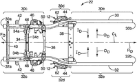
- FIG. 2 is a bottom view (looking upward) of a frame of the vehicle depicted in FIG. 1 , showing side members of the frame with the stop structures fixed to corresponding ones of the side members at opposite lateral sides of the frame in accordance with the first embodiment;
- FIG. 3 is a perspective view of one of the side members showing a corresponding one of the stop structures fixed thereto and a conduit that is at least partially concealed within concaved areas in each of a bottom surface and a forward-facing surface of the stop structure in accordance with the first embodiment;
- FIG. 4 is a side view of the one of the side members showing the stop structure fixed thereto and the conduit partially concealed within concaved areas in each of the bottom surface and the forward-facing surface of the stop structure in accordance with the first embodiment;
- FIG. 5 is a perspective view of a forward portion of the stop member and adjacent portion of the side member of the frame showing the conduit secured to the side member via a bracket and ring clamp in accordance with the first embodiment;
- FIG. 6 is a bottom view of the side member and stop structure of the frame showing the concaved area formed on the bottom surface of the stop structure with the conduit installed along the concaved area in accordance with the first embodiment;
- FIG. 7 is a top cross-sectional view of the forward portion of the side member and the stop structure taken along the line 7 - 7 in FIG. 4 , showing the conduit extending along the concaved area of the front surface of the stop structure in accordance with the first embodiment;
- FIG. 8 is a cross-sectional view of the forward portion of the side member and the stop structure taken along the line 8 - 8 in FIG. 4 , showing the conduit extending along the concaved area of the bottom surface of the stop structure in accordance with the first embodiment;
- FIG. 9 is a perspective view of a wheel well area of the vehicle depicted in FIG. 1 , showing a portion of the side member, a forward portion of the stop structure and the conduit extending along the concaved area of the forward-facing surface of the stop structure, and showing the conduit secured to the side member via a bracket and ring clamp in accordance with a second embodiment;
- FIG. 10 is another perspective view of a wheel well area of the vehicle showing a portion of the side member, a forward portion of the stop structure and the conduit secured to the side member via the bracket and the ring clamp in accordance with a second embodiment.
- FIG. 1 a vehicle 10 with a stop structure 12 ( FIG. 2 ) is illustrated in accordance with a first embodiment.
- the vehicle 10 is depicted as a heavy-duty pickup truck. However, it should be understood from the drawings and the description herein, that the vehicle 10 can alternatively be an SUV (sports utility vehicle) or passenger vehicle such as a sedan or a coupe.
- SUV sport utility vehicle
- passenger vehicle such as a sedan or a coupe.
- the vehicle 10 includes a frame 14 .
- the frame 14 is therefore a rigid, strong structure able to withstand heavy duty usage.
- the frame 14 and the stop structure 12 described below can be configured for smaller vehicles or larger vehicles and is not limited to usage in a heavy-duty truck such as the vehicle 10 .
- the stop structure 12 can be used on any size vehicle that includes a frame such as or similar to the frame 14 .
- a body structure 16 that defines a passenger compartment 18 attaches to and is supported by the frame 14 .
- the body structure 16 also defines an engine compartment 20 located forward of the passenger compartment 18 and a cargo area 22 located rearward of the passenger compartment 18 .
- the stop structure 12 can also be employed with a unibody vehicle.
- a unibody vehicle is a vehicle that does not typically includes a separate frame such as the frame 14 . Rather, the unibody vehicle includes various structural elements welded together such that body panel provide strength and rigidity thereby replacing some of the structural elements that define the frame 14 . Elements of the unibody vehicle serve as frame elements functionally equivalent to the elements of the frame 14 .
- U.S. Pat. No. 8,870,267 assigned to Nissan North America discloses a unibody vehicle body structure.
- 8,870,267 are basically vehicle side members, such as those of the frame 14 (described in greater detail below).
- U.S. Pat. No. 9,180,913 also assigned to Nissan North America, also discloses a unibody vehicle body structure and further discloses an engine cradle.
- the elements of the stop structure 12 can be installed to portions of the unibody vehicle disclosed in U.S. Pat. No. 8,870,267 and portions of the engine cradle of U.S. Pat. No. 8,870,267.
- Both U.S. Pat. No. 8,870,267 and U.S. Pat. No. 9,180,913 are incorporated herein by reference in their entirety. Since unibody vehicles are conventional structures, further description is omitted for the sake of brevity.
- FIG. 2 several directions relative to the frame 14 (and the vehicle 10 ) are shown in order to define orientations of the various features of the vehicle 10 and the stop structure 12 .
- the vehicle 10 and the frame 14 define a longitudinal center line C L that extends in a lengthwise direction of the vehicle 10 along a central portion of the vehicle 10 .
- a forward direction F D is indicated by the depicted arrow
- a rearward direction R D is indicated by the depicted arrow.
- inboard directions I D and outboard directions O D relative to the longitudinal center line C L are also shown in FIG. 2 .
- the frame 14 includes a first side member 30 , a second side member 32 , a first cross-member 34 , a second cross-member 36 and a third cross-member 38 and an optional front cross-member 40 .
- FIG. 2 shows an underside of the frame 14 . In other words, the depiction of the frame 14 is taken from below the frame 14 looking upward.
- the frame 14 is made of heavy gauge steel, but, can alternatively be made of other materials depending upon the overall design of the vehicle 10 . It should therefore be understood that the first side member 30 extends along and under a driver's side of the vehicle 10 , and the second side member 32 extends along and under a passenger's side of the vehicle 10 .
- the first side member 30 is an elongated beam (a first side member) that has multiple contours and shapes. Specifically, the first side member 30 has a front end 30 a and a rear end 30 b. The first side member 30 also has a first portion 30 c, a second portion 30 d and a third portion 30 e. The first portion 30 c extends in the rearward direction RD from the front end 30 a to a location proximate the second cross-member 36 . The first portion 30 c is generally straight.
- the second portion 30 d has a curved shape such that just rearward of the first portion 30 c, the second portion 30 d gradually curves in the outboard direction O D .
- the third portion 30 e is generally straight, but can include contours and curves, depending upon the overall design of the vehicle 10 .
- the second side member 32 is an elongated beam (a second side member) that has multiple contours and shapes that are symmetrical to the first side member 30 .
- the second side member 32 has a front end 32 a and a rear end 32 b.
- the second side member 32 also has a first portion 32 c, a second portion 32 d and a third portion 32 e.
- the first portion 32 c extends in the rearward direction R D from the front end 32 a to a location proximate the second cross-member 36 .
- the first portion 32 c is generally straight.
- the second portion 32 d has a curved shape such that just rearward of the first portion 32 c, the second portion 32 d gradually curves in the outboard direction O D .
- the first portions 30 c and 32 c of the first and second side members 30 and 32 are a first distance away from one another, and the third portions 30 e and 32 e are a second distance away from one another, with the second distance being greater than the first distance.
- the first and second side members 30 and 32 each include vehicle body attachment flanges 42 and 44 (cabin attachment flanges).
- the attachment flanges 42 and 44 are welded to the first and second side members 30 and 32 and are dimensioned and shaped to attach to the body structure 14 of the vehicle 10 .
- the attachment flanges 42 extend from outboard sides of the first portions 30 c and 32 c of the first and second side members 30 and 32 forward of the first cross-member 34 .
- the attachment flanges 44 extend from outboard sides of the second portions 30 d and 32 d of the first and second side members 30 and 32 rearward of the second cross-member 36 .
- the third portions 30 e and 32 e of the first and second side members 30 and 32 can also include body attachment flanges configured for attachment to structures that define the cargo area 20 of the vehicle 10 . Further, the third portions 30 e and 32 e can be at the same level above the ground as the first portions 30 c and 32 c, or, can be raised above the ground at a level higher that the first portions 30 c and 32 c, with the second portions 30 d and 32 d including an upward curvature. As shown in FIGS. 3-6 , the second side member 32 has an upper surface 32 f and a lower surface 32 g.
- each of the first portions 30 c and 32 c of the first and second side members 30 and 32 further include front suspension structures such as coil spring supports 46 , first suspension structures 48 and second suspension structures 50 .
- the coil spring supports 46 are rigidly fixed (i.e. welded) to respective ones of the first and second side members 30 and 32 .
- the coil spring supports 46 are dimensioned and shaped to support lower ends of front suspension coil springs in a conventional manner. Since front suspension coil springs are conventional structures, further description is omitted for the sake of brevity.
- the first suspension structures 48 are defined by pairs of flanges welded to lower surfaces of the first and second side members 30 and 32 .
- the second suspension structures 50 are defined by pairs of flanges welded to lower surfaces of the first and second side members 30 and 32 rearward and spaced apart from the first suspension structures 48 .
- the first suspension structures 48 are adjacent to or aligned with the first cross-member 34 .
- the second suspension structures 50 are adjacent to or aligned with the second cross-member 36 .
- the first suspension structures 48 and the second suspension structures 50 are configured to support a lower control arm 52 for pivotal movement about pivot bolts 54 .
- the lower control arm 52 is part of the steering and suspension structure of the vehicle 10 . Since steering and suspension structures (and, in particular, control arm structures) are conventional vehicle components, further description is omitted for the sake of brevity.
- the engine compartment 20 of the body structure 16 is approximately located in the space above and between the first portions 30 c and 32 c of the first and second side members 30 and 32 .
- a front portion of the passenger compartment 18 is located in the space above and between the second portions 30 d and 32 d of the first and second side member rearward of the engine compartment 20 .
- the remainder of the passenger compartment 18 and the cargo area 22 of the body structure 14 are located above the third portions 30 e and 32 e of the first and second side members 30 and 32 .
- FIGS. 2-10 A description of the vehicle body attachment flange 44 (referred to hereinafter as the cabin attachment flange 44 ) and the stop structure 12 is now provided with specific reference to FIGS. 2-10 .
- One is fixed to the first side member 30 and the other fixed to the second side member 32 .
- Each of the cabin attachment flanges 44 is identical to the other, except that the cabin attachment flanges 44 are symmetrical mirror images of one another. For the sake of brevity, only one of the cabin attachment flanges 44 is described herein below.
- the cabin attachment flange 44 is fixed to an outboard surface 32 h of the side member 32 .
- the cabin attachment flange 44 basically includes an upper plate 56 and a support flange 58 .
- the upper plate 56 of the cabin attachment flange 44 has a forward section 56 a that defines the top surface of the stop structure 12 and a rearward section 56 b that extends rearward from the forward section 56 a and rearward of the stop structure 12 .
- the support flange 58 is vertically oriented and is welded to both a rearward end of the upper plate 56 and the outboard surface 32 h of the side member 32 .
- the support flange 58 has an outboard surface that is partially visible in FIG. 3 .
- stop structures 12 installed to the frame 22 of the vehicle 10 .
- One is fixed to the first side member 30 and the other fixed to the second side member 32 .
- Each of the stop structures 12 is identical to the other, except that they stop structures 12 are symmetrical mirror images of one another. For the sake of brevity, only one of the stop structures 12 is described herein below.
- the second side member 32 is referred to as the side member 32 .
- the stop structure 12 is installed to the side member 32 at a location rearward of the front suspension structure 50 . Further, the stop structure 12 extends in an outboard direction O D from the side member 32 .
- the stop structure 12 is a rigid structure made of metal that is welded or otherwise rigidly and fixedly attached to the outboard surface 32 h of the side member 32 .
- the stop structure 12 has a top surface defined by the forward section 56 a of the upper plate 56 of the cabin attachment flange 44 , a bottom surface 62 , a forward-facing surface 64 and a rear surface 66 .
- the bottom surface 62 has a concaved area 62 a that extends from the forward-facing surface 64 to the rear surface 66 .
- the concaved area 62 a is dimensioned to receive a conduit 70 such that the conduit 70 is received and is at least partially concealed within the concaved area 62 a.
- the concaved area 62 a is horizontally oriented.
- the forward-facing surface 64 has another concaved area 64 a that extends from the top surface 56 a to the bottom surface 62 .
- the concaved area 64 a is dimensioned to receive the conduit 70 such that the conduit 70 is received and is at least partially concealed within the concaved area 64 a.
- the concaved area 64 a is vertically oriented.
- the bottom surface 62 of the stop structure 12 includes a main section 62 b. As shown in FIG. 4 , the main section 62 b of the bottom surface 62 of the stop structure 12 is located vertically higher than the bottom surface 32 g of the side member 32 . Further, the concaved area 62 a of the bottom surface 62 being located vertically higher that the main section 62 b of the bottom surface 62 of the stop structure 12 and the bottom surface 32 g of the side member 32 .
- top surface of the stop structure 12 defined by the forward section 56 a of the upper plate 56 of the cabin attachment flange 44 is located vertically lower than the top surface 32 f of the side member 32 .
- the concaved area 62 a of the bottom surface 62 is located adjacent to the outboard surface 32 h of the first side member 32 .
- the concaved area 64 a of the forward-facing surface 64 is also located adjacent to the outboard surface 32 h of the first side member 32 .
- the rearward section 56 b of the cabin attachment flange 44 extends rearward from the rear surface 66 of the stop structure 12 .
- the forward-facing surface 64 of the stop structure 12 further includes a stop surface 64 b and an outboard most surface 64 c.
- the stop surface 64 b defines an angle relative to the vehicle longitudinal direction (the longitudinal center line C L ) that is between 110 and 130 degrees.
- the conduit 70 includes a hollow interior with a plurality of electric wires extending therethrough.
- the conduit 70 further includes a rear section 70 a with a connector 70 b, a mid-section 70 b, a curved section 70 c and an upwardly extending section 70 d.
- the rear section 70 a of the conduit 70 and the connector 70 b are located rearward of the stop structure 12 .
- the mid-section 70 b, of the conduit 70 is located within the concaved area 62 a of the bottom surface 62 of the stop structure 12 .
- the curved section 70 c of the conduit 70 is at least partially located within the concaved area 64 a of the forward-facing surface 64 of the stop structure 12 .
- the upwardly extending section 70 d of the conduit 70 extends upward from the curved section 70 c to a dashwall 76 of the body structure 16 and into the engine compartment 20 .
- a portion of the upwardly extending section 70 d of the conduit 70 extends adjacent to a front wheel well 78 of the body structure 16 prior to entering the engine compartment 20 .
- the upwardly extending section 70 d of the conduit 70 is held in place by a bracket 74 and a plastic clamp 74 a.
- the bracket 74 is bolted to the upper surface 32 f of the side member 32 .
- the plastic clamp 74 a is fixed to the bracket 74 and clamps around the conduit 70 , as shown in FIGS. 3-6 .
- the wires within the conduit 70 can be used for any of a variety of electrically controlled systems of the vehicle 10 , such as tail lamps, turn signal lamps, electric door locks, electric door opening mechanisms, and/or electric windows. Such systems are conventional features well known in the art. Therefore, description of these systems is omitted for the sake of brevity.
- the concaved areas 62 a and 64 a provide a space to route wires within the conduit 70 along the frame 14 is a simple and protected manner. Further, since the conduit 70 is at least partially concealed within the concaved areas 62 a and 64 a, the conduit 70 is generally hidden from view.
- conduit 70 can also be used to route fluid filled tubes and/or hoses therethrough.
- a tube that supplies windshield washer fluid to a rear window of the vehicle 10 can be routed through the conduit 70 .
- a coolant hose or refrigerant hoses can be routed through the conduit for secondary heating and air conditioning systems located in a rearward area of the passenger compartment 18 .
- FIGS. 9 and 10 a bracket 174 and clamp 174 a in accordance with a second embodiment will now be explained.
- the parts of the second embodiment that are identical to the parts of the first embodiment will be given the same reference numerals as the parts of the first embodiment.
- the descriptions of the parts of the second embodiment that are identical to the parts of the first embodiment may be omitted for the sake of brevity.
- the bracket 174 is attached to the outboard surface 32 h of the side member 32 .
- the clamp 174 a is fixed to one end of the bracket 174 and clamps around the conduit 70 .
- the vehicle 10 , the stop structure 12 and the frame 14 are as described in the first embodiment.
- vehicle features other than the stop structure 12 and conduit 70 are conventional components that are well known in the art. Since such vehicle features are well known in the art, these structures will not be discussed or illustrated in detail herein. Rather, it will be apparent to those skilled in the art from this disclosure that the components can be any type of structure that can be used to carry out the present invention.
- the term “comprising” and its derivatives, as used herein, are intended to be open ended terms that specify the presence of the stated features, elements, components, groups, integers, and/or steps, but do not exclude the presence of other unstated features, elements, components, groups, integers and/or steps.
- the foregoing also applies to words having similar meanings such as the terms, “including”, “having” and their derivatives.
- the terms “part,” “section,” “portion,” “member” or “element” when used in the singular can have the dual meaning of a single part or a plurality of parts.
Landscapes
- Engineering & Computer Science (AREA)
- Mechanical Engineering (AREA)
- Chemical & Material Sciences (AREA)
- Combustion & Propulsion (AREA)
- Transportation (AREA)
- Body Structure For Vehicles (AREA)
Abstract
Description
Claims (19)
Priority Applications (1)
| Application Number | Priority Date | Filing Date | Title |
|---|---|---|---|
| US16/411,968 US10960928B2 (en) | 2019-05-14 | 2019-05-14 | Vehicle structure |
Applications Claiming Priority (1)
| Application Number | Priority Date | Filing Date | Title |
|---|---|---|---|
| US16/411,968 US10960928B2 (en) | 2019-05-14 | 2019-05-14 | Vehicle structure |
Publications (2)
| Publication Number | Publication Date |
|---|---|
| US20200361540A1 US20200361540A1 (en) | 2020-11-19 |
| US10960928B2 true US10960928B2 (en) | 2021-03-30 |
Family
ID=73228309
Family Applications (1)
| Application Number | Title | Priority Date | Filing Date |
|---|---|---|---|
| US16/411,968 Active 2039-10-11 US10960928B2 (en) | 2019-05-14 | 2019-05-14 | Vehicle structure |
Country Status (1)
| Country | Link |
|---|---|
| US (1) | US10960928B2 (en) |
Families Citing this family (2)
| Publication number | Priority date | Publication date | Assignee | Title |
|---|---|---|---|---|
| US11602985B2 (en) * | 2019-09-11 | 2023-03-14 | Ford Global Technologies, Llc | Continuous cooling assembly |
| US20230022240A1 (en) * | 2021-06-29 | 2023-01-26 | Electric Last Mile, Inc., Debtor, c/o David W. Carickhoff, Chapter 7 Trustee | Front body vehicle assembly |
Citations (13)
| Publication number | Priority date | Publication date | Assignee | Title |
|---|---|---|---|---|
| US8393669B2 (en) * | 2008-06-24 | 2013-03-12 | Toyota Jidosha Kabushiki Kaisha | Vehicle frame structure |
| US8807597B2 (en) * | 2010-02-18 | 2014-08-19 | Ford Global Technologies, Llc | Frontal collision energy absorption structure for vehicle |
| US8985258B1 (en) * | 2014-05-30 | 2015-03-24 | Ford Global Technologies, Llc | Vehicle frame component |
| US20150246690A1 (en) * | 2014-03-03 | 2015-09-03 | Toyota Jidosha Kabushiki Kaisha | Vehicle framework structure |
| US20150321700A1 (en) | 2014-05-08 | 2015-11-12 | Toyota Jidosha Kabushiki Kaisha | Vehicle front section structure |
| US20180022388A1 (en) | 2016-07-21 | 2018-01-25 | Nissan Motor Light Truck Co., Ltd. | Vehicle frame |
| US9956992B1 (en) | 2016-10-31 | 2018-05-01 | Nissan North America, Inc. | Vehicle structure |
| US10065586B2 (en) * | 2016-11-22 | 2018-09-04 | Ford Global Technologies, Llc | Deployable device mounted to vehicle frame |
| US10093358B2 (en) | 2016-10-31 | 2018-10-09 | Nissan North America, Inc. | Vehicle structure |
| US10256015B2 (en) * | 2013-08-09 | 2019-04-09 | Tdk Corporation | R-t-b based sintered magnet and rotating machine |
| US20190152530A1 (en) * | 2017-11-20 | 2019-05-23 | Toyota Jidosha Kabushiki Kaisha | Vehicle lower portion structure |
| US10315700B2 (en) * | 2014-06-09 | 2019-06-11 | Gordon Murray Design Limited | Vehicle impact structures |
| US10780921B2 (en) * | 2018-04-06 | 2020-09-22 | Toyota Jidosha Kabushiki Kaisha | Vehicle frame structure |
-
2019
- 2019-05-14 US US16/411,968 patent/US10960928B2/en active Active
Patent Citations (14)
| Publication number | Priority date | Publication date | Assignee | Title |
|---|---|---|---|---|
| US8393669B2 (en) * | 2008-06-24 | 2013-03-12 | Toyota Jidosha Kabushiki Kaisha | Vehicle frame structure |
| US8807597B2 (en) * | 2010-02-18 | 2014-08-19 | Ford Global Technologies, Llc | Frontal collision energy absorption structure for vehicle |
| US10256015B2 (en) * | 2013-08-09 | 2019-04-09 | Tdk Corporation | R-t-b based sintered magnet and rotating machine |
| US20150246690A1 (en) * | 2014-03-03 | 2015-09-03 | Toyota Jidosha Kabushiki Kaisha | Vehicle framework structure |
| US20150321700A1 (en) | 2014-05-08 | 2015-11-12 | Toyota Jidosha Kabushiki Kaisha | Vehicle front section structure |
| US8985258B1 (en) * | 2014-05-30 | 2015-03-24 | Ford Global Technologies, Llc | Vehicle frame component |
| US10315700B2 (en) * | 2014-06-09 | 2019-06-11 | Gordon Murray Design Limited | Vehicle impact structures |
| US20180022388A1 (en) | 2016-07-21 | 2018-01-25 | Nissan Motor Light Truck Co., Ltd. | Vehicle frame |
| US9988090B2 (en) * | 2016-07-21 | 2018-06-05 | Nissan Motor Light Truck Co., Ltd. | Vehicle frame |
| US9956992B1 (en) | 2016-10-31 | 2018-05-01 | Nissan North America, Inc. | Vehicle structure |
| US10093358B2 (en) | 2016-10-31 | 2018-10-09 | Nissan North America, Inc. | Vehicle structure |
| US10065586B2 (en) * | 2016-11-22 | 2018-09-04 | Ford Global Technologies, Llc | Deployable device mounted to vehicle frame |
| US20190152530A1 (en) * | 2017-11-20 | 2019-05-23 | Toyota Jidosha Kabushiki Kaisha | Vehicle lower portion structure |
| US10780921B2 (en) * | 2018-04-06 | 2020-09-22 | Toyota Jidosha Kabushiki Kaisha | Vehicle frame structure |
Also Published As
| Publication number | Publication date |
|---|---|
| US20200361540A1 (en) | 2020-11-19 |
Similar Documents
| Publication | Publication Date | Title |
|---|---|---|
| US9731766B2 (en) | Front vehicle body structure | |
| CN106864596B (en) | Front vehicle body structure | |
| JP2002362415A (en) | Body structure | |
| US9242674B2 (en) | Rear vehicle body reinforcing structure | |
| US20200207198A1 (en) | Vehicle battery support | |
| DE102016121326A1 (en) | Front vehicle body reinforcement structure | |
| US10526017B2 (en) | Vehicle body structure | |
| KR102934936B1 (en) | Front vehicle body structure | |
| CN108216373B (en) | Vehicle body reinforcing structure adapted to small overlap collision | |
| US8596713B1 (en) | Apparatus for assembling fender panel of vehicle | |
| CN109866833B (en) | Roof rack structure for passenger cars | |
| US20190225270A1 (en) | Vehicle frame and vehicle having same | |
| US11117619B2 (en) | Vehicle frame assembly | |
| US10960928B2 (en) | Vehicle structure | |
| JP3848563B2 (en) | Vehicle front structure | |
| CN110294030A (en) | Vehicle body lower surface configuration | |
| US11541714B2 (en) | Vehicle | |
| JPH08142909A (en) | Car body rear structure | |
| CN109562774A (en) | The bearing assembly of steering column for vehicle and vehicle with such bearing assembly | |
| US12312004B2 (en) | Subframe for vehicle | |
| US10793192B2 (en) | Bracket node assembly for a vehicle, vehicle frame assembly having same and vehicle having same | |
| US20240190506A1 (en) | Structural assembly having angled deflector | |
| CN118636975A (en) | Front panel assembly, body structure and vehicle | |
| US11643150B2 (en) | Vehicle cargo structure | |
| EP3543091A1 (en) | Vehicle-body side face structure |
Legal Events
| Date | Code | Title | Description |
|---|---|---|---|
| AS | Assignment |
Owner name: NISSAN NORTH AMERICA, INC., TENNESSEE Free format text: ASSIGNMENT OF ASSIGNORS INTEREST;ASSIGNOR:GRATTAN, PATRICK;REEL/FRAME:049176/0440 Effective date: 20190514 |
|
| FEPP | Fee payment procedure |
Free format text: ENTITY STATUS SET TO UNDISCOUNTED (ORIGINAL EVENT CODE: BIG.); ENTITY STATUS OF PATENT OWNER: LARGE ENTITY |
|
| STPP | Information on status: patent application and granting procedure in general |
Free format text: NOTICE OF ALLOWANCE MAILED -- APPLICATION RECEIVED IN OFFICE OF PUBLICATIONS |
|
| STPP | Information on status: patent application and granting procedure in general |
Free format text: PUBLICATIONS -- ISSUE FEE PAYMENT VERIFIED |
|
| STCF | Information on status: patent grant |
Free format text: PATENTED CASE |
|
| AS | Assignment |
Owner name: NISSAN MOTOR CO., LTD., JAPAN Free format text: ASSIGNMENT OF ASSIGNORS INTEREST;ASSIGNOR:NISSAN NORTH AMERICA, INC.;REEL/FRAME:057728/0037 Effective date: 20210628 |
|
| MAFP | Maintenance fee payment |
Free format text: PAYMENT OF MAINTENANCE FEE, 4TH YEAR, LARGE ENTITY (ORIGINAL EVENT CODE: M1551); ENTITY STATUS OF PATENT OWNER: LARGE ENTITY Year of fee payment: 4 |