US10960587B2 - Keycap forming method - Google Patents
Keycap forming method Download PDFInfo
- Publication number
- US10960587B2 US10960587B2 US16/017,192 US201816017192A US10960587B2 US 10960587 B2 US10960587 B2 US 10960587B2 US 201816017192 A US201816017192 A US 201816017192A US 10960587 B2 US10960587 B2 US 10960587B2
- Authority
- US
- United States
- Prior art keywords
- male mold
- keycap
- mold
- stabilizer bar
- forming method
- Prior art date
- Legal status (The legal status is an assumption and is not a legal conclusion. Google has not performed a legal analysis and makes no representation as to the accuracy of the status listed.)
- Expired - Fee Related, expires
Links
Images


Classifications
-
- B—PERFORMING OPERATIONS; TRANSPORTING
- B29—WORKING OF PLASTICS; WORKING OF SUBSTANCES IN A PLASTIC STATE IN GENERAL
- B29C—SHAPING OR JOINING OF PLASTICS; SHAPING OF MATERIAL IN A PLASTIC STATE, NOT OTHERWISE PROVIDED FOR; AFTER-TREATMENT OF THE SHAPED PRODUCTS, e.g. REPAIRING
- B29C45/00—Injection moulding, i.e. forcing the required volume of moulding material through a nozzle into a closed mould; Apparatus therefor
- B29C45/03—Injection moulding apparatus
- B29C45/04—Injection moulding apparatus using movable moulds or mould halves
- B29C45/0441—Injection moulding apparatus using movable moulds or mould halves involving a rotational movement
-
- B—PERFORMING OPERATIONS; TRANSPORTING
- B29—WORKING OF PLASTICS; WORKING OF SUBSTANCES IN A PLASTIC STATE IN GENERAL
- B29C—SHAPING OR JOINING OF PLASTICS; SHAPING OF MATERIAL IN A PLASTIC STATE, NOT OTHERWISE PROVIDED FOR; AFTER-TREATMENT OF THE SHAPED PRODUCTS, e.g. REPAIRING
- B29C45/00—Injection moulding, i.e. forcing the required volume of moulding material through a nozzle into a closed mould; Apparatus therefor
- B29C45/14—Injection moulding, i.e. forcing the required volume of moulding material through a nozzle into a closed mould; Apparatus therefor incorporating preformed parts or layers, e.g. injection moulding around inserts or for coating articles
- B29C45/14549—Coating rod-like, wire-like or belt-like articles
-
- B—PERFORMING OPERATIONS; TRANSPORTING
- B29—WORKING OF PLASTICS; WORKING OF SUBSTANCES IN A PLASTIC STATE IN GENERAL
- B29L—INDEXING SCHEME ASSOCIATED WITH SUBCLASS B29C, RELATING TO PARTICULAR ARTICLES
- B29L2031/00—Other particular articles
- B29L2031/767—Printing equipment or accessories therefor
- B29L2031/7676—Keyboards
Definitions
- the present invention relates to a keyboard device, and more particularly to a keycap forming method for a keyboard device.
- the widely-used peripheral input device of a computer system includes for example a mouse device, a keyboard device, a trackball device, or the like. Via the keyboard device, characters or symbols can be inputted into the computer system directly. As a consequence, most users and most manufacturers of input devices pay much attention to the development of keyboard devices.
- the subject of the present invention is related to a keyboard device.
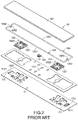
- FIG. 1 is a schematic top view illustrating the outer appearance of a conventional keyboard device.
- plural key structures 10 and 10 ′ are disposed on a top surface of the conventional keyboard device 1 .
- the key structures 10 have the ordinary sizes.
- the key structures 10 ′ are relatively longer. That is, the length of the key structure 10 is slightly larger than the width of the key structure 10 , and the length L 1 of the key structure 10 ′ is much larger than the width W 1 of the key structure 10 ′.
- the user may depress the key structures 10 and 10 ′ to input corresponding English letters (or symbols) or numbers or execute various functions (e.g., F1 ⁇ F12 or Delete).
- the conventional keyboard device 1 is a keyboard for a notebook computer.
- FIG. 2 is a schematic exploded view illustrating a portion of the conventional keyboard device and taken along a viewpoint.
- FIG. 3 is a schematic exploded view illustrating a portion of the conventional keyboard device and taken along another viewpoint.
- the conventional keyboard device 1 comprises plural key structures 10 and 10 ′, a metallic base plate 11 and a membrane circuit board 12 .
- the membrane circuit board 12 comprises plural membrane switches 121 corresponding to the plural key structures 10 and 10 ′.
- Each of the plural key structures 10 and 10 ′ comprises a keycap 101 , at least one scissors-type connecting element 102 and a rubbery elastomer 103 .
- the scissors-type connecting element 102 is connected between the keycap 101 and the metallic base plate 11 .
- the scissors-type connecting element 102 comprises a first frame 1021 and a second frame 1022 .
- the second frame 1022 is pivotally coupled to the first frame 1021 . Consequently, the first frame 1021 and the second frame 1022 can be swung relative to each other.
- the rubbery elastomer 103 is arranged between the keycap 101 and the metallic base plate 11 .
- the rubbery elastomer 103 comprises a contacting part 1031 .
- the first frame 1021 and the second frame 1022 of the scissors-type connecting element 102 are switched from an open-scissors state to a stacked state.
- the corresponding membrane switch 121 is pushed and triggered by the contacting part 1031 of the rubbery elastomer 103 . Consequently, the membrane circuit board 12 generates a corresponding key signal.
- the keycap 101 of the key structure 10 or 10 ′ When the keycap 101 of the key structure 10 or 10 ′ is no longer depressed, the keycap 101 is moved upwardly relative to the metallic base plate 11 in response to an elastic force of the rubbery elastomer 103 . Meanwhile, the first frame 1021 and the second frame 1022 are switched from the stacked state to the open-scissors state again, and the keycap 101 is returned to its original position.
- the key structures 10 ′ and the key structures 10 are distinguished. As shown in the drawings, the length L 1 of the key structure 10 ′ is much larger than the width W 1 of the key structure 10 ′. Since the length L 1 of the keycap 101 of the key structure 10 ′ is relatively longer, the keycap 101 is readily rocked while the key structure 10 ′ is depressed. That is, the operating smoothness of the key structure 10 ′ is adversely affected, and even the tactile feel of the user is impaired.
- the key structure 10 ′ is further equipped with a special mechanism.
- the key structure 10 ′ further comprises a first stabilizer bar 104 , a second stabilizer bar 105 and plural hooks 106 .
- the first stabilizer bar 104 comprises a first linking bar part 1041 and two first hook parts 1042 .
- the two first hook parts 1042 are located at two ends of the first stabilizer bar 104 , respectively.
- the second stabilizer bar 105 comprises a second linking bar part 1051 and two second hook parts 1052 .
- the two second hook parts 1052 are located at two ends of the second stabilizer bar 105 , respectively.
- the metallic base plate 11 comprises a first connecting structure 111 and a second connecting structure 112 .
- the first connecting structure 111 and the second connecting structure 112 are protruded upwardly, and penetrated through the membrane circuit board 12 .
- the first connecting structure 111 comprises a first locking hole 1111 and a third locking hole 1112 .
- the second connecting structure 112 comprises a second locking hole 1121 and a fourth locking hole 1122 .
- the second locking hole 1121 corresponds to the first locking hole 1111 .
- the fourth locking hole 1122 corresponds to the third locking hole 1112 .
- the first linking bar part 1041 of the first stabilizer bar 104 and the second linking bar part 1051 of the second stabilizer bar 105 are pivotally coupled to the corresponding hooks 106 of the keycap 101 of the key structure 10 ′.
- the two first hook parts 1042 of the first stabilizer bar 104 are penetrated through the first locking hole 1111 of the first connecting structure 111 and the second locking hole 1121 of the second connecting structure 112 , respectively.
- the two second hook parts 1052 of the second stabilizer bar 105 are penetrated through the third locking hole 1112 of the first connecting structure 111 and the fourth locking hole 1122 of the second connecting structure 112 , respectively.
- FIG. 4 schematically illustrates the actions of the first stabilizer bar and the second stabilizer bar of the conventional keyboard device. While the keycap 101 of the key structure 10 ′ is moved upwardly or downwardly relative to the metallic base plate 11 , the first stabilizer bar 104 is moved in a first direction D 11 or a second direction D 12 and rotated in a first rotating direction D 13 or a second rotating direction D 14 . Similarly, the second stabilizer bar 105 is moved in the first direction D 11 or the second direction D 12 and rotated in the first rotating direction D 13 or the second rotating direction D 14 .
- the key structure 10 ′ is kept stable and not inclined while the key structure 10 ′ is moved upwardly or downwardly relative to the metallic base plate 11 . Moreover, the uses of the first stabilizer bar 104 and the second stabilizer bar 105 are helpful to increase the strength of the keycap 101 .
- the arrangements of the first stabilizer bar 104 and the second stabilizer bar 105 have the above advantages. However, since it is necessary to assemble the first stabilizer bar 104 and the second stabilizer bar 105 with the keycap 101 , the fabricating cost of the keyboard device 1 is increased. Generally, the process of assembling the first stabilizer bar 104 and the second stabilizer bar 105 with the keycap 101 is manually performed. The manual assembling process is time-consuming and labor-intensive. Moreover, since the assembling process is readily erroneous, the hooks 106 of the keycap 101 are possibly broken.
- An object of the present invention provides a keycap forming method for reducing the fabricating cost of a keyboard device.
- a keycap forming method includes the following steps.
- a step (A) a stabilizer bar is fixed on a first male mold.
- a step (B) a keycap is formed through a second male mold and a female mold according to an injection molding process.
- a step (C) the second male mold and the female mold are separated from each other. Consequently, the keycap is fixed on the female mold.
- a step (D) the first male mold and the female mold are aligned with and stacked on each other. Consequently, the stabilizer bar and the keycap are combined together.
- a step (E) the first male mold and the female mold are separated from each other. Consequently, the stabilizer bar is detached from the first male mold.
- the step (A) includes steps (A1) and (A2).
- the stabilizer bar is moved to the first male mold.
- the stabilizer bar is fixed on plural fixing structures of the first male mold.
- the step (E) includes steps (E1) and (E2).
- the first male mold and the female mold are separated from each other.
- the plural fixing structures is shrunk back into the first male mold to externally push the stabilizer bar, so that the stabilizer bar is detached from the plural fixing structures and fixed on the keycap.
- the step (E) includes steps (E1) and (E3).
- the first male mold and the female mold are separated from each other.
- a first ejecting mechanism of the first male mold is used to push the stabilizer bar, so that the stabilizer bar is detached from the plural fixing structures and fixed on the keycap.
- a first segment of the stabilizer bar is fixed in the hook of the keycap, and a second segment of the stabilizer bar is fixed on the plural fixing structures of the first male mold.
- the present invention provides the keycap forming method.
- the first male mold, the second male mold and the female mold are specially designed for moving the stabilizer bar.
- the stabilizer bar and the keycap are combined together during the process of forming the keycap. After the stabilizer bar is separated from the first male mold, the keycap with the combined stabilizer bar is produced.
- the keycap forming method of the present invention is completely automatic.
- the assembling precision of the keycap forming method of the present invention is higher than that of the manual assembling method. Consequently, the possibility of causing damage of the keycap during the assembling process will be largely reduced.
- FIG. 1 is a schematic top view illustrating the outer appearance of a conventional keyboard device
- FIG. 2 is a schematic exploded view illustrating a portion of the conventional keyboard device and taken along a viewpoint;
- FIG. 3 is a schematic exploded view illustrating a portion of the conventional keyboard device and taken along another viewpoint;
- FIG. 4 schematically illustrates the actions of the first stabilizer bar and the second stabilizer bar of the conventional keyboard device
- FIG. 5 schematically illustrates a first male mold, a second male mold and a female mold of a device for performing a keycap forming method according to an embodiment of the present invention and taken along a viewpoint;
- FIG. 6 schematically illustrates the first male mold, the second male mold and the female mold of the device for performing the keycap forming method according to the embodiment of the present invention and taken along another viewpoint;
- FIG. 7A and FIG. 7B are flowcharts illustrating a keycap forming method according to an embodiment of the present invention.
- FIG. 8 schematically illustrates a step of placing the stabilizer bar on the first male mold according to the keycap forming method of the present invention
- FIG. 9 schematically illustrates a step of stacking the second male mold and the female mold on each other according to the keycap forming method of the present invention
- FIG. 10 schematically illustrates a step of fixing the keycap on the female mold according to the keycap forming method of the present invention
- FIG. 11 schematically illustrates a step of aligning the first male mold with the female mold according to the keycap forming method of the present invention
- FIG. 12 schematically illustrates a step of stacking the first male mold and the female mold on each other according to the keycap forming method of the present invention.
- FIG. 13 is a schematic perspective view illustrating a keycap produced by the keycap forming process according to the embodiment of the present invention.
- the present invention provides a keycap forming method.
- the device for performing the keycap forming method will be illustrated as follows.
- FIG. 5 schematically illustrates a first male mold, a second male mold and a female mold of a device for performing a keycap forming method according to an embodiment of the present invention and taken along a viewpoint.
- FIG. 6 schematically illustrates the first male mold, the second male mold and the female mold of the device for performing the keycap forming method according to the embodiment of the present invention and taken along another viewpoint.
- a first male mold 21 , a second male mold 22 , a female mold 23 , a moving mechanism 24 , a stabilizer bar 3 and a keycap 4 are shown.
- the stabilizer bar 3 comprises a first segment 31 and a second segment 32 .
- the keycap 4 comprises plural hooks 41 .
- the first male mold 21 comprises plural first fixing posts 211 , plural fixing structures 212 corresponding to the stabilizer bar 3 , and a first ejecting mechanism 213 .
- the second male mold 22 comprises plural second fixing posts 221 , a raised structure 222 corresponding to the keycap 4 , plural recesses 223 corresponding to the plural hooks 41 , and a second ejecting mechanism 224 .
- the female mold 23 comprises plural fixing holes 231 and a concave structure 232 .
- the concave structure 232 is aligned with the keycap 4 .
- the raised structure 222 and the plural recesses 223 are collaboratively defined as a core.
- the concave structure 232 is a cavity.
- the moving mechanism 24 is connected with the first male mold 21 and the second male mold 22 . Moreover, the first male mold 21 and the second male mold 22 are movable or rotatable by the moving mechanism 24 .
- FIG. 7A AND FIG. 7B are flowcharts illustrating a keycap forming method according to an embodiment of the present invention.
- the keycap forming method comprises the following steps.
- a step A a stabilizer bar is fixed on a first male mold.
- a step B a keycap is formed through a second male mold and a female mold according to an injection molding process.
- a step C the second male mold and the female mold are separated from each other, so that the keycap is fixed on the female mold.
- the first male mold and the female mold are aligned with and stacked on each other, so that the stabilizer bar and the keycap are combined together.
- a step E the first male mold and the female mold are separated from each other, so that the stabilizer bar is detached from the first male mold.
- the step A comprises steps A1 and A2.
- the stabilizer bar is moved to the first male mold.
- the stabilizer bar is fixed on the plural fixing structures of the first male mold.
- the step B comprises steps B1 and B2.
- the second male mold and the female mold are stacked on each other.
- a molding material is injected according to the injection molding process, so that the keycap is formed.
- the step D comprises steps D1 and D2.
- the first male mold and the second male mold are moved.
- the first male mold and the female mold are aligned with and stacked on each other.
- the step E comprises steps E1, E2 and E3.
- the first male mold and the female mold are separated from each other.
- the plural fixing structures are shrunk back into the first male mold to externally push the stabilizer bar.
- the stabilizer bar is pushed by the first ejecting mechanism of the first male mold, so that the stabilizer bar is detached from the plural fixing structures.
- FIG. 8 schematically illustrates a step of placing the stabilizer bar on the first male mold according to the keycap forming method of the present invention.
- the step A1 is performed to move the stabilizer bar 3 to the first male mold 21 .
- the stabilizer bar 3 is clamped and moved by a robotic arm or any other appropriate clamping tool.
- the step A2 is performed to fix the stabilizer bar 3 on the plural fixing structures 212 of the first male mold 21 . Consequently, the stabilizer bar 3 is not escaped from the first male mold 21 .
- the second segment 32 of the stabilizer bar 3 is fixed on the plural fixing structures 212 .
- the method of producing the stabilizer bar 3 is not restricted. However, the stabilizer bar 3 needs to be produced before the keycap forming method is performed.
- FIG. 9 schematically illustrates a step of stacking the second male mold and the female mold on each other according to the keycap forming method of the present invention.
- the step B1 is performed.
- the moving mechanism 24 is moved in a first direction V 1 .
- the second male mold 22 and the female mold 23 are stacked on each other.
- the plural second fixing posts 221 are inserted into the corresponding fixing holes 231 . Consequently, the second male mold 22 and the female mold 23 are not shifted toward the left and right sides.
- the molding material is injected into the space between the second male mold 22 and the female mold 23 (i.e., the space between the raised structure 222 and the concave structure 232 ). Consequently, the keycap 4 is formed.
- the injected molding material is filled into the plural recesses 223 of the second male mold 22 . Consequently, the plural hooks 41 of the keycap 4 are formed.
- the molding material is made of a plastic material.
- FIG. 10 schematically illustrates a step of fixing the keycap on the female mold according to the keycap forming method of the present invention.
- the step C is performed.
- the moving mechanism 24 is moved in a second direction V 2 , which is opposite to the first direction V 1 .
- the second male mold 22 is moved with the moving mechanism 24
- the second male mold 22 and the female mold 23 are separated from each other.
- the keycap 4 is fixed in the concave structure 232 of the female mold 23 .
- the moving mechanism 24 is moved in the second direction V 2 to move the second male mold 22
- the second ejecting mechanism 224 of the second male mold 22 is moved in the first direction V 1 .
- the second ejecting mechanism 224 is protruded out of the second male mold 22 to push the keycap 4 in the first direction V 1 . Consequently, the keycap 4 is detached from the second male mold 22 . At the same time, the keycap 4 is fixed in the concave structure 232 of the female mold 23 .
- the second ejecting mechanism 224 of the second male mold 22 is an angle lifter. The operations of the angle lifter are well known to those skilled in the art, and are not redundantly described herein.
- FIG. 11 schematically illustrates a step of aligning the first male mold with the female mold according to the keycap forming method of the present invention.
- FIG. 12 schematically illustrates a step of stacking the first male mold and the female mold on each other according to the keycap forming method of the present invention.
- the method of aligning the first male mold 21 with the female mold 23 is well known to those skilled in the art, and is not redundantly described herein.
- the fixing structures 212 of the first male mold 21 and the female mold 23 are precisely designed. Consequently, when the first male mold 21 is moved to the position under the female mold 23 and aligned with the female mold 23 , the plural hooks 41 of the keycap 4 is located over the first segment 31 of the stabilizer bar 3 (see FIG. 11 ).
- the step D2 is performed.
- the rotation of the moving mechanism 24 is stopped, and the moving mechanism 24 is moved in the first direction V 1 to move the first male mold 21 . Consequently, the first male mold 21 and the female mold 23 are stacked on each other (see FIG. 12 ).
- the plural first fixing posts 211 are inserted into the corresponding fixing holes 231 . Consequently, the first male mold 21 and the female mold 23 are not shifted toward the left and right sides.
- the stabilizer bar 3 and the keycap 4 are combined together.
- the stabilizer bar 3 is still connected with the first male mold 21 .
- the first segment 31 of the stabilizer bar 3 is fixed in the plural hooks 41 of the keycap 4
- the second segment 32 of the first segment 31 is fixed on the plural fixing structures 212 of the first male mold 21 .
- the step E1 is performed.
- the moving mechanism 24 is moved in the second direction V 2 .
- the plural fixing structures 212 are shrunk back into the first male mold 21 , so that the stabilizer bar 3 is externally pushed by the first male mold 21 .
- the stabilizer bar 3 is pushed by the first ejecting mechanism 213 of the first male mold 21 , so that the stabilizer bar 3 is detached from the plural fixing structures 212 .
- the stabilizer bar 3 is only fixed on the plural hooks 41 of the keycap 4 . Consequently, the process of combining the stabilizer bar 3 with the keycap 4 is completed (see FIG. 13 ).
- the step E comprises the steps E1, E2 and E3. Consequently, a stronger force is provided to externally push the stabilizer bar 3 to facilitate separating the stabilizer bar 3 from the first male mold 21 . It is noted that numerous modifications and alterations may be made while retaining the teachings of the invention.
- the step E comprises the steps E1 and E2, or the step E comprises the steps E1 and E3. Consequently, a weaker force is provided to externally push the stabilizer bar 3 .
- the present invention provides the keycap forming method.
- the first male mold, the second male mold and the female mold are specially designed for moving the stabilizer bar.
- the stabilizer bar and the keycap are combined together during the process of forming the keycap. After the stabilizer bar is separated from the first male mold, the keycap with the combined stabilizer bar is produced.
- the keycap forming method of the present invention is completely automatic.
- the assembling precision of the keycap forming method of the present invention is higher than that of the manual assembling method. Consequently, the possibility of causing damage of the keycap during the assembling process will be largely reduced.
Landscapes
- Engineering & Computer Science (AREA)
- Manufacturing & Machinery (AREA)
- Mechanical Engineering (AREA)
- Input From Keyboards Or The Like (AREA)
Abstract
Description
Claims (9)
Applications Claiming Priority (2)
| Application Number | Priority Date | Filing Date | Title |
|---|---|---|---|
| TW107112780A TWI680046B (en) | 2018-04-13 | 2018-04-13 | Method for forming keycap |
| TW107112780 | 2018-04-13 |
Publications (2)
| Publication Number | Publication Date |
|---|---|
| US20190315030A1 US20190315030A1 (en) | 2019-10-17 |
| US10960587B2 true US10960587B2 (en) | 2021-03-30 |
Family
ID=68160172
Family Applications (1)
| Application Number | Title | Priority Date | Filing Date |
|---|---|---|---|
| US16/017,192 Expired - Fee Related US10960587B2 (en) | 2018-04-13 | 2018-06-25 | Keycap forming method |
Country Status (2)
| Country | Link |
|---|---|
| US (1) | US10960587B2 (en) |
| TW (1) | TWI680046B (en) |
Citations (2)
| Publication number | Priority date | Publication date | Assignee | Title |
|---|---|---|---|---|
| US4535210A (en) * | 1984-04-18 | 1985-08-13 | Illinois Tool Works Inc. | Keyswitch stabilizing device |
| US20190371545A1 (en) * | 2018-06-01 | 2019-12-05 | Primax Electronics Ltd. | Keycap forming method |
Family Cites Families (5)
| Publication number | Priority date | Publication date | Assignee | Title |
|---|---|---|---|---|
| CN102201292A (en) * | 2010-03-26 | 2011-09-28 | 毅嘉科技股份有限公司 | Manufacturing method of keycap shell and keyboard with keycap shell |
| TW201223733A (en) * | 2010-12-10 | 2012-06-16 | Ichia Tech Inc | Method for making keycap |
| CN204471740U (en) * | 2015-02-09 | 2015-07-15 | 何修云 | A kind of production mould of Double color keyboard button |
| CN205291465U (en) * | 2016-01-21 | 2016-06-08 | 杨志钢 | A kind of two-color keycap production mold and the two-color keycap produced therewith |
| CN207009334U (en) * | 2017-06-30 | 2018-02-13 | 东莞市欧希德精密模具有限公司 | A key cap with invisible character effect |
-
2018
- 2018-04-13 TW TW107112780A patent/TWI680046B/en not_active IP Right Cessation
- 2018-06-25 US US16/017,192 patent/US10960587B2/en not_active Expired - Fee Related
Patent Citations (2)
| Publication number | Priority date | Publication date | Assignee | Title |
|---|---|---|---|---|
| US4535210A (en) * | 1984-04-18 | 1985-08-13 | Illinois Tool Works Inc. | Keyswitch stabilizing device |
| US20190371545A1 (en) * | 2018-06-01 | 2019-12-05 | Primax Electronics Ltd. | Keycap forming method |
Also Published As
| Publication number | Publication date |
|---|---|
| TW201943534A (en) | 2019-11-16 |
| TWI680046B (en) | 2019-12-21 |
| US20190315030A1 (en) | 2019-10-17 |
Similar Documents
| Publication | Publication Date | Title |
|---|---|---|
| US7893376B2 (en) | Key structure with scissors-type connecting member | |
| US6706986B2 (en) | Scissors-like linkage structure, key switch including the structure and method of assembling the same | |
| US9000313B2 (en) | Scissors-type connecting member and key structure with scissors-type connecting member | |
| US20120193202A1 (en) | Key structure of keyboard device | |
| US9941073B2 (en) | Keyboard device | |
| US20170277227A1 (en) | Keyboard and notebook computer with same | |
| EP3608937B1 (en) | Keyboard, electronic device and assembly method of the keyboard | |
| US20220189715A1 (en) | Key structure | |
| US9959992B1 (en) | Keyboard device | |
| US20180075987A1 (en) | Key structure | |
| US10607793B1 (en) | Keyboard device | |
| US20230187148A1 (en) | Key structure | |
| US10832877B2 (en) | Keycap forming method | |
| US20140138223A1 (en) | Scissors-type connecting member and key structure with scissors-type connecting member | |
| US9799465B2 (en) | Key structure | |
| US20170278651A1 (en) | Keyboard | |
| US9633800B1 (en) | Key structure | |
| US10960587B2 (en) | Keycap forming method | |
| US10636592B2 (en) | Keyboard device | |
| US9847190B1 (en) | Mechanism to raise and lower the height of keys within a keyboard | |
| US9959989B2 (en) | Key structure | |
| US8563886B2 (en) | Key structure with scissors-type connecting member | |
| US11646167B1 (en) | Keyboard device and key structure thereof | |
| CN110556257B (en) | Forming method of button cap | |
| US20220399171A1 (en) | Keyboard device and key structure thereof |
Legal Events
| Date | Code | Title | Description |
|---|---|---|---|
| AS | Assignment |
Owner name: PRIMAX ELECTRONICS LTD, TAIWAN Free format text: ASSIGNMENT OF ASSIGNORS INTEREST;ASSIGNORS:CHOU, YI-TE;LI, CHE-AN;SIGNING DATES FROM 20180104 TO 20180117;REEL/FRAME:046192/0717 |
|
| FEPP | Fee payment procedure |
Free format text: ENTITY STATUS SET TO UNDISCOUNTED (ORIGINAL EVENT CODE: BIG.); ENTITY STATUS OF PATENT OWNER: LARGE ENTITY |
|
| STPP | Information on status: patent application and granting procedure in general |
Free format text: NON FINAL ACTION MAILED |
|
| STPP | Information on status: patent application and granting procedure in general |
Free format text: PUBLICATIONS -- ISSUE FEE PAYMENT VERIFIED |
|
| STCF | Information on status: patent grant |
Free format text: PATENTED CASE |
|
| FEPP | Fee payment procedure |
Free format text: MAINTENANCE FEE REMINDER MAILED (ORIGINAL EVENT CODE: REM.); ENTITY STATUS OF PATENT OWNER: LARGE ENTITY |
|
| LAPS | Lapse for failure to pay maintenance fees |
Free format text: PATENT EXPIRED FOR FAILURE TO PAY MAINTENANCE FEES (ORIGINAL EVENT CODE: EXP.); ENTITY STATUS OF PATENT OWNER: LARGE ENTITY |
|
| STCH | Information on status: patent discontinuation |
Free format text: PATENT EXPIRED DUE TO NONPAYMENT OF MAINTENANCE FEES UNDER 37 CFR 1.362 |
|
| FP | Lapsed due to failure to pay maintenance fee |
Effective date: 20250330 |