US10960130B2 - Syringe having a spring action plunger rod - Google Patents
Syringe having a spring action plunger rod Download PDFInfo
- Publication number
- US10960130B2 US10960130B2 US15/421,828 US201715421828A US10960130B2 US 10960130 B2 US10960130 B2 US 10960130B2 US 201715421828 A US201715421828 A US 201715421828A US 10960130 B2 US10960130 B2 US 10960130B2
- Authority
- US
- United States
- Prior art keywords
- plunger rod
- outer sleeve
- syringe barrel
- syringe
- cover
- Prior art date
- Legal status (The legal status is an assumption and is not a legal conclusion. Google has not performed a legal analysis and makes no representation as to the accuracy of the status listed.)
- Active, expires
Links
Images


Classifications
-
- A—HUMAN NECESSITIES
- A61—MEDICAL OR VETERINARY SCIENCE; HYGIENE
- A61M—DEVICES FOR INTRODUCING MEDIA INTO, OR ONTO, THE BODY; DEVICES FOR TRANSDUCING BODY MEDIA OR FOR TAKING MEDIA FROM THE BODY; DEVICES FOR PRODUCING OR ENDING SLEEP OR STUPOR
- A61M5/00—Devices for bringing media into the body in a subcutaneous, intra-vascular or intramuscular way; Accessories therefor, e.g. filling or cleaning devices, arm-rests
- A61M5/002—Packages specially adapted therefor, e.g. for syringes or needles, kits for diabetics
-
- A—HUMAN NECESSITIES
- A61—MEDICAL OR VETERINARY SCIENCE; HYGIENE
- A61M—DEVICES FOR INTRODUCING MEDIA INTO, OR ONTO, THE BODY; DEVICES FOR TRANSDUCING BODY MEDIA OR FOR TAKING MEDIA FROM THE BODY; DEVICES FOR PRODUCING OR ENDING SLEEP OR STUPOR
- A61M5/00—Devices for bringing media into the body in a subcutaneous, intra-vascular or intramuscular way; Accessories therefor, e.g. filling or cleaning devices, arm-rests
- A61M5/178—Syringes
- A61M5/31—Details
- A61M5/315—Pistons; Piston-rods; Guiding, blocking or restricting the movement of the rod or piston; Appliances on the rod for facilitating dosing ; Dosing mechanisms
- A61M5/31511—Piston or piston-rod constructions, e.g. connection of piston with piston-rod
-
- A—HUMAN NECESSITIES
- A61—MEDICAL OR VETERINARY SCIENCE; HYGIENE
- A61M—DEVICES FOR INTRODUCING MEDIA INTO, OR ONTO, THE BODY; DEVICES FOR TRANSDUCING BODY MEDIA OR FOR TAKING MEDIA FROM THE BODY; DEVICES FOR PRODUCING OR ENDING SLEEP OR STUPOR
- A61M5/00—Devices for bringing media into the body in a subcutaneous, intra-vascular or intramuscular way; Accessories therefor, e.g. filling or cleaning devices, arm-rests
- A61M5/178—Syringes
- A61M5/31—Details
- A61M5/3129—Syringe barrels
- A61M5/3135—Syringe barrels characterised by constructional features of the proximal end
-
- A—HUMAN NECESSITIES
- A61—MEDICAL OR VETERINARY SCIENCE; HYGIENE
- A61M—DEVICES FOR INTRODUCING MEDIA INTO, OR ONTO, THE BODY; DEVICES FOR TRANSDUCING BODY MEDIA OR FOR TAKING MEDIA FROM THE BODY; DEVICES FOR PRODUCING OR ENDING SLEEP OR STUPOR
- A61M5/00—Devices for bringing media into the body in a subcutaneous, intra-vascular or intramuscular way; Accessories therefor, e.g. filling or cleaning devices, arm-rests
- A61M5/178—Syringes
- A61M5/31—Details
- A61M5/315—Pistons; Piston-rods; Guiding, blocking or restricting the movement of the rod or piston; Appliances on the rod for facilitating dosing ; Dosing mechanisms
- A61M5/31501—Means for blocking or restricting the movement of the rod or piston
-
- A—HUMAN NECESSITIES
- A61—MEDICAL OR VETERINARY SCIENCE; HYGIENE
- A61M—DEVICES FOR INTRODUCING MEDIA INTO, OR ONTO, THE BODY; DEVICES FOR TRANSDUCING BODY MEDIA OR FOR TAKING MEDIA FROM THE BODY; DEVICES FOR PRODUCING OR ENDING SLEEP OR STUPOR
- A61M5/00—Devices for bringing media into the body in a subcutaneous, intra-vascular or intramuscular way; Accessories therefor, e.g. filling or cleaning devices, arm-rests
- A61M5/178—Syringes
- A61M5/31—Details
- A61M5/32—Needles; Details of needles pertaining to their connection with syringe or hub; Accessories for bringing the needle into, or holding the needle on, the body; Devices for protection of needles
- A61M5/3202—Devices for protection of the needle before use, e.g. caps
-
- B—PERFORMING OPERATIONS; TRANSPORTING
- B65—CONVEYING; PACKING; STORING; HANDLING THIN OR FILAMENTARY MATERIAL
- B65D—CONTAINERS FOR STORAGE OR TRANSPORT OF ARTICLES OR MATERIALS, e.g. BAGS, BARRELS, BOTTLES, BOXES, CANS, CARTONS, CRATES, DRUMS, JARS, TANKS, HOPPERS, FORWARDING CONTAINERS; ACCESSORIES, CLOSURES, OR FITTINGS THEREFOR; PACKAGING ELEMENTS; PACKAGES
- B65D77/00—Packages formed by enclosing articles or materials in preformed containers, e.g. boxes, cartons, sacks or bags
- B65D77/10—Container closures formed after filling
- B65D77/20—Container closures formed after filling by applying separate lids or covers, i.e. flexible membrane or foil-like covers
-
- B—PERFORMING OPERATIONS; TRANSPORTING
- B65—CONVEYING; PACKING; STORING; HANDLING THIN OR FILAMENTARY MATERIAL
- B65D—CONTAINERS FOR STORAGE OR TRANSPORT OF ARTICLES OR MATERIALS, e.g. BAGS, BARRELS, BOTTLES, BOXES, CANS, CARTONS, CRATES, DRUMS, JARS, TANKS, HOPPERS, FORWARDING CONTAINERS; ACCESSORIES, CLOSURES, OR FITTINGS THEREFOR; PACKAGING ELEMENTS; PACKAGES
- B65D77/00—Packages formed by enclosing articles or materials in preformed containers, e.g. boxes, cartons, sacks or bags
- B65D77/22—Details
- B65D77/30—Opening or contents-removing devices added or incorporated during filling or closing of containers
- B65D77/32—Tearing-strings or like flexible elements
-
- A—HUMAN NECESSITIES
- A61—MEDICAL OR VETERINARY SCIENCE; HYGIENE
- A61M—DEVICES FOR INTRODUCING MEDIA INTO, OR ONTO, THE BODY; DEVICES FOR TRANSDUCING BODY MEDIA OR FOR TAKING MEDIA FROM THE BODY; DEVICES FOR PRODUCING OR ENDING SLEEP OR STUPOR
- A61M5/00—Devices for bringing media into the body in a subcutaneous, intra-vascular or intramuscular way; Accessories therefor, e.g. filling or cleaning devices, arm-rests
- A61M5/178—Syringes
- A61M5/31—Details
- A61M5/315—Pistons; Piston-rods; Guiding, blocking or restricting the movement of the rod or piston; Appliances on the rod for facilitating dosing ; Dosing mechanisms
- A61M5/31511—Piston or piston-rod constructions, e.g. connection of piston with piston-rod
- A61M2005/31518—Piston or piston-rod constructions, e.g. connection of piston with piston-rod designed to reduce the overall size of an injection device, e.g. using flexible or pivotally connected chain-like rod members
Definitions
- the present invention is directed to a pre-filled syringe assembly adapted for the dispensing and delivery of a fluid. More particularly, the present invention is directed to a pre-filled syringe assembly having a spring actuated plunger rod resulting in a smaller packaging footprint allowing for reduced storage space. The present invention is also directed to a packaging system for a pre-filled syringe assembly that prevents unintended actuation of the plunger rod and reduces the likelihood of tampering of the syringe contents.
- a conventional syringe typically includes a syringe barrel with an opening at one end and a plunger mechanism disposed through the other end.
- the plunger typically includes a plunger rod extending through the barrel, with a plunger head or stopper at the end of the plunger rod within the barrel and with a finger flange at the other end of the plunger rod extending out of the barrel.
- the plunger rod is retracted through the syringe barrel to fill the syringe barrel with a fluid, such as a medication, with the plunger rod extending out from the rear end of the syringe barrel.
- a fluid such as a medication
- the opening of the syringe barrel is adapted for fluid communication with a patient, such as through a hypodermic needle fitted at the front end of the syringe barrel or through a luer-type fitting extending from the front end of the syringe barrel for attachment with a fluid line of a patient.
- hypodermic syringes may be packaged as “pre-filled” devices, wherein the syringe is pre-filled with medication prior to being packaged and delivered to the end user. In this manner, there is no need for the user to fill the device prior to injection, thereby saving time for the end user and maintaining consistent volumes for delivery.
- Pre-filled syringes and pre-filled metered dose syringes are often filled with narcotics or other drugs at a production facility, packaged, and then shipped to a medical facility. Once at the facility, these syringes are often placed in controlled storage and/or locked cabinets to reduce theft of the syringes themselves and/or theft of the contents of these syringes.
- a tamper-proof cap for a pre-filled syringe including a top member concentrically disposed in a generally cylindrical sleeve member and connected by frangible elements to the sleeve member is conventionally known.
- an outer cap for a pre-filled syringe that is covered with a cylindrical cover cap which connects with the top wall of a holding member through a frangible portion.
- the cylindrical cover cap may be broken from the top wall of the holding member for tampering prevention/tamper-proof evidence.
- a syringe assembly in accordance with an embodiment of the present invention, includes a syringe barrel having a first end, a second end, and a sidewall extending between the first end and the second end defining a chamber.
- the syringe assembly also includes a stopper disposed within the chamber of the syringe barrel.
- the syringe assembly further includes a plunger rod associated with the stopper, the plunger rod having an outer sleeve having a distal end interconnected to the stopper, the outer sleeve including a sidewall portion defining an opening therein, and an inner sleeve disposed within the outer sleeve, the inner sleeve including a longitudinally extending track, at least a portion of the track being in alignment with an opening in the outer sleeve.
- the inner sleeve is adapted for telescopic movement with respect to the outer sleeve.
- the plunger rod also includes a spring mounted in association with the inner sleeve.
- the syringe assembly further includes a holding mechanism associated with the plunger rod and configured for cooperation with the inner and outer sleeves, wherein relative movement between the inner sleeve and the outer sleeve causes the plunger rod to transition from a collapsed pre-use position to an extended ready-to-use position.
- the relative movement between the inner and outer sleeves causes relative movement between the inner and outer sleeves to release the spring from a compressed position and transitions the plunger rod to the ready-to-use position.
- the plunger rod is transitionable from a pre-use position, in which the spring is in a compressed position and the inner sleeve is collapsed within the outer sleeve, and a ready-to-use position in which the spring is expanded and the inner sleeve is extended out from the outer sleeve.
- the opening in the outer sleeve has a longitudinally extending opening and the holding mechanism includes a flexible finger associated with the outer sleeve and the longitudinally extending opening.
- the holding mechanism can be a separate member that is secured to the outer sleeve or it can be integrally formed with the outer sleeve.
- the flexible finger can include a laterally extending member that is configured for cooperation with the opening in the outer sleeve and with the track in the inner sleeve, and the distally directed force applied to the inner sleeve causes relative movement between the laterally extending member and the track to release the spring from the compressed position and allow the inner sleeve of the plunger rod to transition from the collapsed pre-use position to the extended ready-to-use position.
- the longitudinally extending track can extend through a sidewall portion of the inner sleeve and the track can include a first stop and a second stop. The distally directed force causes disengagement of the laterally extending member from the first stop and release of the spring.
- This disengagement results in proximal movement of the inner sleeve with respect to the outer sleeve from the collapsed pre-use position to the extended ready-to-use position.
- the laterally extending member moves along the longitudinally extending track and locks in the second stop to maintain the inner sleeve in the ready-to-use position.
- the flexible finger can be configured to flex in a lateral direction with respect to the longitudinally extending track, and the opening in the outer sleeve can be configured to disengage the laterally extending member from the first stop and engage the second stop upon release and expansion of the spring.
- the inner sleeve can include a locking finger configured for cooperating with an aperture in the outer sleeve, for locking the plunger rod in the extended ready-to-use position, and for preventing pull-out of the inner sleeve from the outer sleeve.
- the syringe assembly can also include a stop member associated with the outer sleeve and configured to cooperate with the syringe barrel to limit movement of the outer sleeve into the syringe barrel upon the application of the distally directed force to the plunger rod.
- This feature can comprise a flex finger that prevents the application of a partial dose from a pre-filled syringe as it prevents the depression of the outer sleeve into the syringe barrel until expansion of the inner sleeve with respect to the outer sleeve.
- the syringe assembly can include an alignment member associated with at least one of the inner sleeve and the outer sleeve to prevent relative rotation of the inner sleeve with respect to the outer sleeve.
- the alignment member can comprise a keyed track.
- the holding mechanism can comprise a spring finger and a U-shaped locking member cooperating with the outer sleeve and the longitudinally extending track of the inner sleeve.
- the syringe assembly may include a medication or drug disposed within the syringe barrel.
- the plunger rod assembly includes an inner sleeve disposed within the outer sleeve and mounted for telescopic movement with respect to the outer sleeve, and a spring mounted in association with the inner sleeve.
- a longitudinally extending track is associated with the inner sleeve.
- the plunger rod assembly further includes a holding mechanism associated with a plunger rod and configured for cooperation with the inner and outer sleeves, wherein relative movement between the outer sleeve and the inner sleeve causes the plunger rod to transition from a collapsed pre-use position to an extended ready-to-use position.
- the holding mechanism comprises a flexible finger associated with the outer sleeve.
- the flexible finger can include a laterally extending member configured for cooperation with the opening in the outer sleeve and with the track in the inner sleeve and wherein the distally directed force applied to the inner sleeve causes relative movement between the flexible finger, the laterally extending member, and the track to release the spring from the compressed position and allow the inner sleeve of the plunger rod to transition from the collapsed pre-use position to the extended ready-to-use position.
- the longitudinally extending track can extend through a sidewall portion of the inner sleeve and can include a first stop and a second stop and wherein the distally directed force causes: disengagement of the laterally extending member from the first stop; release of the spring; and proximal movement of the inner sleeve with respect to the outer sleeve.
- the laterally extending member locks in the second stop to maintain the inner sleeve in the ready-to-use position.
- the inner sleeve of the plunger rod assembly can include a locking finger configured for cooperating with an aperture in the outer sleeve for locking the plunger rod in the extended ready-to-use position and for preventing pull-out of the inner sleeve from the outer sleeve.
- the plunger rod assembly can further include a stop member associated with the outer sleeve and configured to cooperate with a syringe barrel to limit movement of the outer sleeve into the syringe barrel upon the application of the distally directed force to the plunger rod.
- the holding mechanism can comprise a spring finger and a U-shaped locking member cooperating with the outer sleeve and the longitudinally extending track of the inner sleeve.
- a packaging assembly for use with a pre-filled syringe assembly having a spring released plunger rod includes a cap configured for covering the plunger rod and a cover molded about a syringe barrel and a tip cap.
- the cover can be a tamper-indicating label and can be connected to the cap with a frangible portion.
- the cap can comprise a rigid member configured to prevent the application of a distally directed force on the plunger rod.
- the packaging assembly can include a tear tab positioned about a portion of the plunger rod at a location between a plunger rod thumb press and a syringe barrel flange.
- a cover can be molded about the syringe barrel and tip cap.
- the tear tab can include a grasping portion to assist in removal of the tear tab from about the plunger rod and can be configured to prevent distal movement of the spring released plunger rod and inadvertent release of the spring released plunger rod.
- the cover can include a tamper-indicating member. This tamper-indicating member can be in the form of a colored frangible attachment portion, wherein this frangible portion assists in the removal of the cover from about the syringe barrel and tip cap.
- FIG. 1 is a front perspective view of a syringe assembly having a spring action plunger rod in a collapsed position in accordance with an embodiment of the present invention.
- FIG. 1A is cross-sectional side perspective view of the syringe assembly of FIG. 1 in which the packaging components have been included in accordance with an embodiment of the present invention.
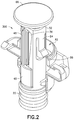
- FIG. 2 is a front perspective view of the plunger rod of FIG. 1 including a portion of the syringe barrel in accordance with an embodiment of the present invention.
- FIG. 2A is a side perspective view of an outer sleeve of the plunger rod of FIG. 2 in accordance with an embodiment of the present invention.
- FIG. 2B is a side perspective view of an inner sleeve of the plunger rod of FIG. 2 in accordance with an embodiment of the present invention.
- FIG. 3 is an expanded perspective view of the syringe assembly of FIG. 1 in accordance with an embodiment of the present invention.
- FIG. 4A is a side perspective view of the syringe assembly of FIG. 1 showing a locking flex finger in accordance with an embodiment of the present invention.
- FIG. 4B is a cross-sectional view of the syringe assembly of FIG. 4A in accordance with an embodiment of the present invention.
- FIG. 5A is a cross-sectional view of the syringe assembly of FIG. 1 with the plunger rod in the collapsed position showing the partial dose prevention feature in accordance with an embodiment of the present invention.
- FIG. 5B is a cross-sectional view of the syringe assembly of FIG. 1 with the plunger rod in the extended position showing the partial dose prevention feature in accordance with an embodiment of the present invention.
- FIG. 6 is a front perspective view of the syringe assembly of the invention having a spring action plunger rod in a collapsed position in accordance with an embodiment of the present invention.
- FIG. 6A is a partially expanded view of the syringe assembly of FIG. 6 in accordance with an embodiment of the present invention.
- FIG. 6B is a front perspective view of the plunger rod of FIG. 6 in accordance with an embodiment of the present invention.
- FIG. 7 is a front perspective view of the packaging arrangement for a syringe assembly having a spring action plunger rod in accordance with an embodiment of the present invention.
- FIGS. 8A-8C are perspective side views of a packaging assembly for the syringe assembly having a spring action plunger rod illustrating the operational steps for removal of the packaging assembly in accordance with an embodiment of the present invention.
- FIGS. 1, 1A, 2, 2A-2B, 3, 4A-4B, and 5A-5B depict a syringe assembly according to an embodiment of the invention, generally indicated as 10 , adapted for the dispensing and delivery of a fluid.
- FIGS. 7 and 8A-8C depict differing packaging assemblies, generally indicated as 200 and 300 , which can be used for packaging the syringe assembly of the invention.
- the syringe assembly 10 is intended for use for injection or infusion of fluid, such as a medication, directly into a patient, and is generally shown and described for purposes of the present description as a hypodermic syringe.
- Syringe assembly 10 is contemplated for use in connection with a needle such as by connecting syringe assembly 10 to a separate needle assembly (not shown), or alternatively for connection with a separate intravenous (IV) connection assembly (not shown).
- the syringe assembly 10 includes a syringe barrel 12 having a first or distal end 14 , a second or proximal end 16 , and a sidewall 18 extending between the distal end 14 and proximal end 16 defining an interior chamber 20 of the syringe barrel 12 .
- a stopper 22 is slidably disposed within the chamber 20 of the syringe barrel 12 .
- the syringe barrel 12 may be in the general form of an elongated cylindrical barrel as is known in the art for the general shape of a hypodermic syringe, although other forms for containing a fluid for delivery are also contemplated by the present invention.
- the syringe barrel 12 may be formed of glass, or may be injection molded from thermoplastic material such as polypropylene and polyethylene according to techniques known to those of ordinary skill in the art, though it is to be appreciated that the syringe barrel 12 may be made from other suitable materials and according to other applicable techniques.
- the syringe barrel 12 may include an outwardly extending flange 21 about at least a portion of the proximal end 16 .
- the flange 21 may be configured for easy grasping by a medical practitioner, as will be discussed herein.
- the distal end 14 of the syringe barrel 12 terminates in a tip 24 having an outlet opening 26 .
- the proximal end 16 is generally open-ended, but is intended to be closed off to the external environment, via the stopper 22 , as will be discussed herein.
- the syringe assembly 10 can include a tip cap 54 , an interface member 53 interfacing between the tip cap 54 and the tip 24 of the syringe barrel 12 , and a plug 55 , for sealing the outlet opening 26 .
- the syringe barrel 12 may include markings, such as graduations on the sidewall 18 thereof, for providing an indication as to the level or amount of fluid contained within the syringe barrel 12 .
- markings may be provided on the external wall, the internal wall, or integrally formed or otherwise within the wall of syringe barrel 12 .
- the markings may provide a description of the contents of the syringe, or other identifying information, as may be known in the art.
- All of the components of syringe assembly 10 may be constructed of any known material, and are desirably constructed of medical grade polymers. As stated above, the syringe assembly 10 is particularly useful as a pre-filled syringe, and therefore may be provided for end use with a fluid, such as a medication, contained within interior chamber 20 of syringe barrel 12 , pre-filled by the manufacturer. In this manner, syringe assembly 10 can be manufactured, pre-filled with a medication, sterilized, and packaged in appropriate packaging for delivery, storage, and use by the end user, without the need for the end user to fill the syringe with medication from a separate vial prior to use.
- a fluid such as a medication
- the syringe assembly 10 includes a plunger rod, generally indicated as 30 , associated with the stopper 22 .
- the plunger rod 30 has an outer sleeve 32 having a distal end 34 interconnected to the stopper 22 .
- the outer sleeve 32 includes an opening 36 extending through a sidewall portion 38 .
- An inner sleeve 40 is mounted for telescopic movement within the outer sleeve 32 .
- This inner sleeve 40 includes a longitudinally extending track 42 .
- the plunger rod 30 When assembled within the outer sleeve 32 , at least a portion of the track 42 is in alignment with the opening 36 in the outer sleeve 32 .
- the plunger rod 30 also includes a spring 44 mounted within and in association with the inner sleeve 40 .
- the syringe assembly 10 further includes a holding mechanism, generally indicated as 46 , associated with the plunger rod 30 and configured for cooperation with the inner sleeve 40 and outer sleeve 32 , wherein an application of a distally directed force DF, as shown in FIG. 5A , to the plunger rod 30 causes the plunger rod 30 to transition from a collapsed pre-use position, as shown in FIGS. 1, 1A, 2, and 5A , to an extended ready-to-use position, as shown in FIG. 5B .
- a distally directed force DF as shown in FIG. 5A
- the distally directed force DF applied to the plunger rod causes relative movement between the inner sleeve 40 and outer sleeve 32 to release the spring 44 from a compressed position and allow the plunger rod 30 to extend to the ready-to-use position.
- FIGS. 1A and 5A which show the pre-use position
- the spring 44 is in the compressed position and the inner sleeve 40 is collapsed within the outer sleeve 32 .
- FIG. 5B the spring 44 is expanded and the inner sleeve 40 is extended out from the outer sleeve 32 . Once the inner sleeve 40 is extended, it becomes locked in this position, as described in more detail below, and the plunger rod 30 and syringe 10 is ready for use.
- the opening 36 in the outer sleeve 32 can have a longitudinally extending shape which extends along a longitudinal axis L, as shown in FIG. 3 .
- the holding mechanism 46 associated with the outer sleeve 32 , can include a flexible finger 48 that bisects the opening into a first open portion 50 and a second open portion 52 .
- the holding mechanism 46 can be a separate member, including a base portion 58 , and the flexible finger 48 that is secured to the outer sleeve 32 such as with a mechanical attachment member, adhesive, fusing, and the like, or the holding mechanism 46 can be integrally formed with the outer sleeve 32 .
- the flexible finger 48 of the holding mechanism 46 can include a laterally extending member 68 , such as in the form of a finger, that extends in a lateral direction, with respect to the longitudinal length of the flexible finger 48 and into a barrel or interior 70 of the outer sleeve 32 .
- a laterally extending member 68 such as in the form of a finger, that extends in a lateral direction, with respect to the longitudinal length of the flexible finger 48 and into a barrel or interior 70 of the outer sleeve 32 .
- the finger 48 extends into the track 42 of the inner sleeve 40 .
- this laterally extending member 68 is contained within the first stop 62 .
- the application of a distally directed force to the inner sleeve 40 of the plunger rod 30 causes the laterally extending member 68 to interact with the inclined surface 72 of the first stop 62 and ride along this surface 72 . This interaction then causes the flexible finger 48 to flex in a lateral direction LF, as shown in FIG. 2A , which allows the laterally extending member 68 to become disengaged from the first stop 62 and to enter into the longitudinal portion 65 of the track 42 in the inner sleeve 40 .
- the laterally extending member 68 is located within the longitudinal portion 65 of the track, the inner sleeve 40 and the outer sleeve 32 are no longer locked together and the spring 44 , associated with the inner sleeve 40 , is released.
- the spring 44 can be associated with any internal portion of the inner sleeve 40 , such as shown by 74 in FIGS. 5A and 5B , so that once compression force on the spring 44 is released, the spring 44 is biased so that it expands and forces the inner sleeve 40 to move in a proximal direction with respect to the distal end 14 of the syringe assembly 10 so that the inner sleeve 40 extends out from the outer sleeve 32 , placing the plunger rod 30 in the extended, ready-to-use position.
- the laterally extending member 68 moves along the longitudinal portion 65 of the longitudinally extending track 42 and locks in the second stop 64 of the inner sleeve 40 to maintain the inner sleeve 40 and plunger rod 30 in the ready-to-use position.
- the inner sleeve 40 can include a locking finger 76 which, in addition to the locking achieved by the longitudinal portion 65 and the second stop 64 , provides additional locking of the inner sleeve 40 within the outer sleeve 32 in the extended position.
- the locking finger 76 is configured for cooperating with an aperture 78 in the outer sleeve 32 to lock the plunger rod 30 in the extended ready-to-use position. It can be appreciated that the locking finger 76 can be located at a distal end 79 of a flexible member 80 .
- a space 81 can be provided behind this flexible member 80 in order to allow the flexible member 80 to flex in an inward and outward direction with respect to the longitudinal centerline L of the syringe assembly 10 to enable the locking finger 76 to engage within the aperture 78 .
- This locking arrangement also prevents pull-out of the inner sleeve 40 from the outer sleeve 32 .
- the syringe assembly 10 can also include a stop member, generally indicated as 82 , associated with the outer sleeve 32 and configured to cooperate with the syringe barrel 12 to limit movement of the outer sleeve 32 into the syringe barrel 12 upon the application of the distally directed force DF to the plunger rod 30 .
- a stop member generally indicated as 82 , associated with the outer sleeve 32 and configured to cooperate with the syringe barrel 12 to limit movement of the outer sleeve 32 into the syringe barrel 12 upon the application of the distally directed force DF to the plunger rod 30 .
- this feature can comprise a flex finger 84 having a ramped portion 86 at one end thereof that prevents the application of a partial dose from a pre-filled syringe 10 as it limits or prevents the depression of the outer sleeve 32 into the syringe barrel 12 prior to desired use of the syringe assembly, i.e., until extension of the inner sleeve 40 with respect to the outer sleeve 32 .
- a flex finger 84 having a ramped portion 86 at one end thereof that prevents the application of a partial dose from a pre-filled syringe 10 as it limits or prevents the depression of the outer sleeve 32 into the syringe barrel 12 prior to desired use of the syringe assembly, i.e., until extension of the inner sleeve 40 with respect to the outer sleeve 32 .
- a sidewall portion 88 of the inner sleeve 40 supports or applies a supporting surface against the stop member 82 and, should a distally directed force be applied to the plunger rod 30 , the ramp portion 86 will engage against a top surface 90 of the flange 21 of the syringe barrel to prevent movement of the plunger rod 30 into the syringe barrel 12 and to prevent the application of a partial dose of the syringe contents.
- a syringe assembly includes a spring actuated plunger rod according to another embodiment of the invention.
- the syringe assembly 100 is similar to syringe assembly 10 , as discussed in detail above and includes a first or distal end 114 , a second or proximal end 116 , and a sidewall 118 extending between the distal end 114 and proximal end 116 defining an interior chamber 120 of a syringe barrel 112 .
- a stopper 122 is disposed within the chamber 120 of the syringe barrel 112 .
- the syringe barrel 112 may include an outwardly extending flange 121 about at least a portion of the proximal end 116 .
- the flange 121 may be configured for easy grasping by a medical practitioner.
- the syringe assembly 100 can also include a tip cap 154 .
- a plunger rod assembly 130 includes an outer sleeve 132 and an inner sleeve 140 telescopically mounted within the outer sleeve 132 .
- the outer sleeve 132 is associated with the stopper 122 .
- the outer sleeve 132 includes an opening 136 extending through a sidewall portion 138 .
- the inner sleeve 140 includes a longitudinally extending track 142 , such as a Z-shaped member that extends through a sidewall portion 160 of the inner sleeve 140 .
- the plunger rod assembly 130 When assembled within the outer sleeve 132 , at least a portion of the track 142 is in alignment with the opening 136 in the outer sleeve 132 .
- the plunger rod assembly 130 also includes a spring 144 mounted within and in association with the inner sleeve 140 .
- the syringe assembly 100 further includes a holding mechanism, generally indicated as 146 associated with the plunger rod assembly 130 and configured for cooperation with the inner sleeve 140 and outer sleeve 132 , wherein an application of a distally directed force DF, as shown in FIG. 6 , to the plunger rod assembly 130 causes the plunger rod assembly 130 to transition from a collapsed pre-use position, as shown in FIG. 6 , to an extended ready-to-use position, as shown in FIG. 6B .
- a distally directed force DF as shown in FIG. 6
- the holding mechanism 146 can comprise a spring finger 149 and a U-shaped locking member 151 cooperating with the outer sleeve 132 and the longitudinally extending track 142 of the inner sleeve 140 .
- the longitudinally extending track 142 can include a first stop 162 for containing the spring finger 149 when the inner sleeve 140 is in the collapsed position, and a second stop 164 for containing the spring finger 149 and locking the inner sleeve 140 in place once the inner sleeve 140 is extended from the outer sleeve 132 in the ready-to-use position.
- the U-shaped locking member 151 also prevents pull-out of the inner sleeve 140 from the outer sleeve 132 .
- a longitudinal portion 165 extends between the first stop 162 and the second stop 164 through which the spring finger 149 moves through during expansion of the spring 144 and during transitioning of the plunger rod assembly 130 from the collapsed, pre-use position to the extended ready-to-use position.
- the spring finger 149 is configured to laterally flex LF in two directions, as shown in FIG. 6A to enable it to flex in and out of the first stop 162 and the second stop 164 .
- the syringe assemblies 10 and 100 can include an alignment member associated with at least one of the inner sleeve 40 , 140 and the outer sleeve 32 , 132 to prevent relative rotation of the inner sleeve 40 , 140 with respect to the outer sleeve 32 , 132 .
- this alignment member comprise a keyed track 167 in the outer sleeve 132 .
- FIG. 7 shows a packaging assembly, generally indicated as 200 , for use with a pre-filled syringe assembly 10 , 100 having a spring released plunger rod 30 , 130 in accordance with an embodiment of the present invention.
- This packaging assembly 200 can be used with either type of syringe assembly 10 , 100 , as discussed in detail above.
- the packaging assembly 200 includes a cap 202 configured for covering the plunger rod 30 , 130 , and a cover 204 molded about the syringe barrel 12 , 112 and tip cap 54 , 154 .
- the cover 204 can be a tamper-indicating label, as shown at 206 , and can be of a design known in the art and can include a frangible or perforated portion 208 for ease of removal from the syringe assembly 10 , 100 .
- This frangible portion can include markings, as are known in the art, to indicate if any tampering has occurred.
- One type of label is a shrink-wrap type label which can encompass the tip cap 54 , 154 and a portion of the syringe barrel 12 , 112 and/or cap 202 .
- the cap 202 can comprise a rigid member configured to prevent the application of a distally directed force on the plunger rod 30 , 130 until the cap 202 is removed.
- the cover 204 may comprise a first portion 210 surrounding the syringe barrel 12 , 112 and the tip cap 54 , 154 and a second portion 212 surrounding the syringe barrel flange 21 , 121 .
- the first portion 210 of the cover 204 is removable. When the first portion 210 of the cover 204 is removed, the second portion 212 of the cover 204 remains surrounding the syringe barrel flange 21 , 121 ( FIG. 4B ).
- the second portion 212 of the cover 204 may comprise two parts 214 a , 214 b.
- FIGS. 8A-8C show a packaging assembly, generally indicated as 300 , for use with a pre-filled syringe assembly 10 , 100 having a spring released plunger rod 30 , 130 in accordance with another embodiment of the present invention.
- This packaging assembly 300 can also be used with either type of syringe assembly 10 , 100 , as discussed in detail above.
- the packaging assembly 300 can include a tear tab 302 positioned about a portion of the plunger rod 30 , 130 at a location between a plunger rod thumb press 66 , 166 and the syringe barrel flange 21 , 121 .
- the tear tab 302 is configured to prevent distal movement of the inner sleeve 40 , 140 of the plunger rod 30 , 130 resulting in an inadvertent release of the spring 44 , 144 and extension of the inner sleeve 40 , 140 .
- a cover 304 can be molded about a syringe barrel 12 , 112 and tip cap 54 , 154 .
- the cover 304 can include a tamper-indicating member, such as a colored label 306 , as discussed in detail above, and can include a frangible or perforated portion to assist in the removal of the cover 304 from about the syringe barrel 12 , 112 and tip cap 54 , 154 .
- the tear tab 302 can include a grasping portion 308 , including a roughened portion, to assist in removal of the tear tab 302 from about the plunger rod 30 , 130 .
- the user can remove the tear tab 302 , as shown in FIGS. 8A and 8B and remove the cover 304 .
- the syringe assembly 10 , 100 is now ready for activation of the plunger rod 30 , 130 and subsequent use.
- the cover 304 may comprise a first portion 310 surrounding the syringe barrel 12 , 112 and the tip cap 54 , 154 and a second portion 312 surrounding the syringe barrel flange 21 , 121 .
- the first portion 310 of the cover 304 is removable. When the first portion 310 of the cover 304 is removed, the second portion 312 of the cover 304 remains surrounding the syringe barrel flange 21 , 121 ( FIG. 8C ).
- the syringe assembly embodiments disclosed above result in a syringe assembly having a reduced footprint which is desirable in the packaging of the syringe assemblies as it requires less packaging.
- This reduced footprint provides for syringe assemblies having consistently sized profiles which allow for easy stacking and require less storage space, both of these features being desirable in a controlled storage environment.
Landscapes
- Health & Medical Sciences (AREA)
- Engineering & Computer Science (AREA)
- Hematology (AREA)
- Anesthesiology (AREA)
- Biomedical Technology (AREA)
- Heart & Thoracic Surgery (AREA)
- Vascular Medicine (AREA)
- Life Sciences & Earth Sciences (AREA)
- Animal Behavior & Ethology (AREA)
- General Health & Medical Sciences (AREA)
- Public Health (AREA)
- Veterinary Medicine (AREA)
- Mechanical Engineering (AREA)
- Diabetes (AREA)
- Infusion, Injection, And Reservoir Apparatuses (AREA)
Abstract
Description
Claims (16)
Priority Applications (1)
| Application Number | Priority Date | Filing Date | Title |
|---|---|---|---|
| US15/421,828 US10960130B2 (en) | 2011-09-30 | 2017-02-01 | Syringe having a spring action plunger rod |
Applications Claiming Priority (3)
| Application Number | Priority Date | Filing Date | Title |
|---|---|---|---|
| US201161541618P | 2011-09-30 | 2011-09-30 | |
| US13/622,380 US9597455B2 (en) | 2011-09-30 | 2012-09-19 | Syringe having a spring action plunger rod |
| US15/421,828 US10960130B2 (en) | 2011-09-30 | 2017-02-01 | Syringe having a spring action plunger rod |
Related Parent Applications (1)
| Application Number | Title | Priority Date | Filing Date |
|---|---|---|---|
| US13/622,380 Continuation US9597455B2 (en) | 2011-09-30 | 2012-09-19 | Syringe having a spring action plunger rod |
Publications (2)
| Publication Number | Publication Date |
|---|---|
| US20170143892A1 US20170143892A1 (en) | 2017-05-25 |
| US10960130B2 true US10960130B2 (en) | 2021-03-30 |
Family
ID=47993286
Family Applications (2)
| Application Number | Title | Priority Date | Filing Date |
|---|---|---|---|
| US13/622,380 Active 2033-09-05 US9597455B2 (en) | 2011-09-30 | 2012-09-19 | Syringe having a spring action plunger rod |
| US15/421,828 Active 2032-11-27 US10960130B2 (en) | 2011-09-30 | 2017-02-01 | Syringe having a spring action plunger rod |
Family Applications Before (1)
| Application Number | Title | Priority Date | Filing Date |
|---|---|---|---|
| US13/622,380 Active 2033-09-05 US9597455B2 (en) | 2011-09-30 | 2012-09-19 | Syringe having a spring action plunger rod |
Country Status (2)
| Country | Link |
|---|---|
| US (2) | US9597455B2 (en) |
| WO (1) | WO2013048863A1 (en) |
Cited By (4)
| Publication number | Priority date | Publication date | Assignee | Title |
|---|---|---|---|---|
| US11883260B2 (en) | 2014-12-23 | 2024-01-30 | Automed Patent Holdco, Llc | Delivery apparatus, system and associated methods |
| US11957542B2 (en) | 2020-04-30 | 2024-04-16 | Automed Patent Holdco, Llc | Sensing complete injection for animal injection device |
| USD1108627S1 (en) * | 2023-10-02 | 2026-01-06 | Regeneron Pharmaceuticals, Inc. | Drug-delivery device |
| USD1109322S1 (en) * | 2023-10-02 | 2026-01-13 | Regeneron Pharmaceuticals, Inc. | Drug-delivery device |
Families Citing this family (50)
| Publication number | Priority date | Publication date | Assignee | Title |
|---|---|---|---|---|
| US9656019B2 (en) | 2007-10-02 | 2017-05-23 | Medimop Medical Projects Ltd. | Apparatuses for securing components of a drug delivery system during transport and methods of using same |
| US10420880B2 (en) | 2007-10-02 | 2019-09-24 | West Pharma. Services IL, Ltd. | Key for securing components of a drug delivery system during assembly and/or transport and methods of using same |
| US7967795B1 (en) | 2010-01-19 | 2011-06-28 | Lamodel Ltd. | Cartridge interface assembly with driving plunger |
| JP5653217B2 (en) | 2007-10-02 | 2015-01-14 | メディモップ メディカル プロジェクツ、エル・ティー・ディー | External drug pump |
| US9345836B2 (en) | 2007-10-02 | 2016-05-24 | Medimop Medical Projects Ltd. | Disengagement resistant telescoping assembly and unidirectional method of assembly for such |
| US12097357B2 (en) | 2008-09-15 | 2024-09-24 | West Pharma. Services IL, Ltd. | Stabilized pen injector |
| US9393369B2 (en) | 2008-09-15 | 2016-07-19 | Medimop Medical Projects Ltd. | Stabilized pen injector |
| US10071198B2 (en) | 2012-11-02 | 2018-09-11 | West Pharma. Servicees IL, Ltd. | Adhesive structure for medical device |
| US8157769B2 (en) | 2009-09-15 | 2012-04-17 | Medimop Medical Projects Ltd. | Cartridge insertion assembly for drug delivery system |
| US10071196B2 (en) | 2012-05-15 | 2018-09-11 | West Pharma. Services IL, Ltd. | Method for selectively powering a battery-operated drug-delivery device and device therefor |
| US8348898B2 (en) | 2010-01-19 | 2013-01-08 | Medimop Medical Projects Ltd. | Automatic needle for drug pump |
| US9452261B2 (en) | 2010-05-10 | 2016-09-27 | Medimop Medical Projects Ltd. | Low volume accurate injector |
| USD702834S1 (en) | 2011-03-22 | 2014-04-15 | Medimop Medical Projects Ltd. | Cartridge for use in injection device |
| US10159796B2 (en) | 2011-09-30 | 2018-12-25 | Becton Dickinson France, S.A.S. | Syringe assembly having a telescoping plunger rod |
| US9072827B2 (en) | 2012-03-26 | 2015-07-07 | Medimop Medical Projects Ltd. | Fail safe point protector for needle safety flap |
| US9421323B2 (en) | 2013-01-03 | 2016-08-23 | Medimop Medical Projects Ltd. | Door and doorstop for portable one use drug delivery apparatus |
| CN104129567B (en) * | 2013-04-30 | 2018-08-03 | 麦迪莫普医疗工程有限公司 | The method and related system of the component of fixed drug transport system |
| US9011164B2 (en) | 2013-04-30 | 2015-04-21 | Medimop Medical Projects Ltd. | Clip contact for easy installation of printed circuit board PCB |
| WO2015033953A1 (en) * | 2013-09-06 | 2015-03-12 | テルモ株式会社 | Outer tube for syringe and pre-filled syringe |
| US20150151097A1 (en) * | 2013-12-02 | 2015-06-04 | Biltmore Technologies, Inc. | Nanofluidic delivery system |
| EP3102259B1 (en) * | 2014-02-03 | 2020-03-25 | UNL Holdings LLC | Expanding plunger rods for syringes |
| CA2954928C (en) | 2014-07-31 | 2020-12-15 | Hospira, Inc. | Injection system |
| US9474864B2 (en) | 2014-12-15 | 2016-10-25 | Brell Medical Innovations, LLC | Safety syringe and methods for administration of a medicament dose by subject weight |
| US10293120B2 (en) | 2015-04-10 | 2019-05-21 | West Pharma. Services IL, Ltd. | Redundant injection device status indication |
| US10149943B2 (en) | 2015-05-29 | 2018-12-11 | West Pharma. Services IL, Ltd. | Linear rotation stabilizer for a telescoping syringe stopper driverdriving assembly |
| EP3302652B1 (en) | 2015-06-04 | 2023-09-06 | Medimop Medical Projects Ltd. | Cartridge insertion for drug delivery device |
| EP3316941A1 (en) * | 2015-07-01 | 2018-05-09 | Ipsen Pharma | Syringe assembly |
| US10086145B2 (en) | 2015-09-22 | 2018-10-02 | West Pharma Services Il, Ltd. | Rotation resistant friction adapter for plunger driver of drug delivery device |
| US10576207B2 (en) | 2015-10-09 | 2020-03-03 | West Pharma. Services IL, Ltd. | Angled syringe patch injector |
| US9987432B2 (en) | 2015-09-22 | 2018-06-05 | West Pharma. Services IL, Ltd. | Rotation resistant friction adapter for plunger driver of drug delivery device |
| JP7017512B2 (en) | 2015-10-09 | 2022-02-08 | ウェスト ファーマ サービシーズ イスラエル リミテッド | Bending fluid path type accessories for filled fluid containers |
| JP6579918B2 (en) * | 2015-10-29 | 2019-09-25 | 株式会社吉野工業所 | Syringe type ejector |
| US10646643B2 (en) | 2016-01-21 | 2020-05-12 | West Pharma. Services IL, Ltd. | Needle insertion and retraction mechanism |
| CN111544704B (en) | 2016-01-21 | 2022-06-03 | 西医药服务以色列有限公司 | Force containment in autoinjectors |
| CN113041432B (en) | 2016-01-21 | 2023-04-07 | 西医药服务以色列有限公司 | Medicament delivery device comprising a visual indicator |
| WO2017161076A1 (en) | 2016-03-16 | 2017-09-21 | Medimop Medical Projects Ltd. | Staged telescopic screw assembly having different visual indicators |
| US10376647B2 (en) | 2016-03-18 | 2019-08-13 | West Pharma. Services IL, Ltd. | Anti-rotation mechanism for telescopic screw assembly |
| EP4427776A3 (en) | 2016-06-02 | 2025-02-12 | West Pharma Services IL, Ltd | Three position needle retraction |
| US20170354787A1 (en) * | 2016-06-10 | 2017-12-14 | Brell Medical Innovations, LLC | Safety syringe with dose window |
| US10898658B2 (en) * | 2016-07-06 | 2021-01-26 | LynJohnston, LLC | Compact injection device with telescoping components |
| CN109562220B (en) | 2016-08-01 | 2021-06-29 | 西医药服务以色列有限公司 | Partial door closing prevents spring |
| WO2018026387A1 (en) | 2016-08-01 | 2018-02-08 | Medimop Medical Projects Ltd. | Anti-rotation cartridge pin |
| US11819666B2 (en) | 2017-05-30 | 2023-11-21 | West Pharma. Services IL, Ltd. | Modular drive train for wearable injector |
| WO2019086562A1 (en) * | 2017-11-03 | 2019-05-09 | Sanofi | Plunger and drug delivery device |
| CN111683703B (en) | 2017-12-22 | 2022-11-18 | 西氏医药包装(以色列)有限公司 | Syringe adapted for cartridges of different sizes |
| EP3737443A4 (en) | 2018-01-10 | 2021-10-27 | Lynjohnston, Llc | COMPACT INJECTOR SYSTEMS AND PROCEDURES |
| CN112286249A (en) * | 2019-07-13 | 2021-01-29 | 宁波泽世医疗科技有限公司 | Medicine environment control device |
| EP3821925B1 (en) | 2019-09-18 | 2024-03-20 | KAISHA PACKAGING Private Ltd. | Device for locking a plunger rod of a syringe after use and preventing re-use of the syringe, and syringe assembly |
| USD948714S1 (en) | 2020-06-22 | 2022-04-12 | KAISHA PACKAGING Private Ltd. | Syringe plunger lock |
| CN117138168B (en) * | 2023-08-10 | 2024-08-20 | 北京纳通医用机器人科技有限公司 | Injector piston rod clamping mechanism, pushing injection device and automatic injection surgical robot |
Citations (12)
| Publication number | Priority date | Publication date | Assignee | Title |
|---|---|---|---|---|
| US4333456A (en) | 1981-02-09 | 1982-06-08 | Sterling Drug Inc. | Self-aspirating hypodermic syringe and self-aspirating assembly therefor |
| US4636202A (en) | 1984-07-27 | 1987-01-13 | Syntex (U.S.A.) Inc. | Medicament applicator with plunger assembly and automatically-openable closure therefor |
| US5833669A (en) * | 1993-05-27 | 1998-11-10 | Washington Biotech Corp. | Medicine injection syringe constructions |
| US20020004648A1 (en) | 2000-05-31 | 2002-01-10 | Larsen Carsten Gerner | Disposable double pointed injection needle, and an insulin injection system comprising a disposable double pointed injection needle |
| US20060276755A1 (en) | 2001-01-12 | 2006-12-07 | Becton, Dickinson And Company | Valved Delivery Device and Method |
| US20080167611A1 (en) | 2007-01-04 | 2008-07-10 | Miller Stuart H | Enveloping needle stick protection device |
| US20080202961A1 (en) * | 2007-02-28 | 2008-08-28 | Inviro Medical, Inc. | Sterile packaging of medical devices with enhanced tamper evident, transportation, functional and disposal features |
| WO2009108869A1 (en) | 2008-02-28 | 2009-09-03 | Becton, Dickinson And Company | Syringe with adjustable two piece plunger rod |
| WO2009108847A1 (en) | 2008-02-28 | 2009-09-03 | Becton, Dickinson And Company | Syringe with two piece plunger rod |
| US20100081997A1 (en) | 2006-12-07 | 2010-04-01 | Paul Harry Moed | Dosage delivery device |
| US7815610B2 (en) * | 2004-08-18 | 2010-10-19 | Barry Peter Liversidge | Injection apparatus |
| US20110196313A1 (en) | 2010-02-11 | 2011-08-11 | Allergan, Inc. | Extendable Plunger Rod for Medical Syringe |
-
2012
- 2012-09-19 US US13/622,380 patent/US9597455B2/en active Active
- 2012-09-20 WO PCT/US2012/056290 patent/WO2013048863A1/en not_active Ceased
-
2017
- 2017-02-01 US US15/421,828 patent/US10960130B2/en active Active
Patent Citations (12)
| Publication number | Priority date | Publication date | Assignee | Title |
|---|---|---|---|---|
| US4333456A (en) | 1981-02-09 | 1982-06-08 | Sterling Drug Inc. | Self-aspirating hypodermic syringe and self-aspirating assembly therefor |
| US4636202A (en) | 1984-07-27 | 1987-01-13 | Syntex (U.S.A.) Inc. | Medicament applicator with plunger assembly and automatically-openable closure therefor |
| US5833669A (en) * | 1993-05-27 | 1998-11-10 | Washington Biotech Corp. | Medicine injection syringe constructions |
| US20020004648A1 (en) | 2000-05-31 | 2002-01-10 | Larsen Carsten Gerner | Disposable double pointed injection needle, and an insulin injection system comprising a disposable double pointed injection needle |
| US20060276755A1 (en) | 2001-01-12 | 2006-12-07 | Becton, Dickinson And Company | Valved Delivery Device and Method |
| US7815610B2 (en) * | 2004-08-18 | 2010-10-19 | Barry Peter Liversidge | Injection apparatus |
| US20100081997A1 (en) | 2006-12-07 | 2010-04-01 | Paul Harry Moed | Dosage delivery device |
| US20080167611A1 (en) | 2007-01-04 | 2008-07-10 | Miller Stuart H | Enveloping needle stick protection device |
| US20080202961A1 (en) * | 2007-02-28 | 2008-08-28 | Inviro Medical, Inc. | Sterile packaging of medical devices with enhanced tamper evident, transportation, functional and disposal features |
| WO2009108869A1 (en) | 2008-02-28 | 2009-09-03 | Becton, Dickinson And Company | Syringe with adjustable two piece plunger rod |
| WO2009108847A1 (en) | 2008-02-28 | 2009-09-03 | Becton, Dickinson And Company | Syringe with two piece plunger rod |
| US20110196313A1 (en) | 2010-02-11 | 2011-08-11 | Allergan, Inc. | Extendable Plunger Rod for Medical Syringe |
Cited By (5)
| Publication number | Priority date | Publication date | Assignee | Title |
|---|---|---|---|---|
| US11883260B2 (en) | 2014-12-23 | 2024-01-30 | Automed Patent Holdco, Llc | Delivery apparatus, system and associated methods |
| US11957542B2 (en) | 2020-04-30 | 2024-04-16 | Automed Patent Holdco, Llc | Sensing complete injection for animal injection device |
| US12329610B2 (en) | 2020-04-30 | 2025-06-17 | Automed Patent Holdco Llc | Sensing complete injection for animal injection device |
| USD1108627S1 (en) * | 2023-10-02 | 2026-01-06 | Regeneron Pharmaceuticals, Inc. | Drug-delivery device |
| USD1109322S1 (en) * | 2023-10-02 | 2026-01-13 | Regeneron Pharmaceuticals, Inc. | Drug-delivery device |
Also Published As
| Publication number | Publication date |
|---|---|
| US20130085457A1 (en) | 2013-04-04 |
| US9597455B2 (en) | 2017-03-21 |
| WO2013048863A1 (en) | 2013-04-04 |
| US20170143892A1 (en) | 2017-05-25 |
Similar Documents
| Publication | Publication Date | Title |
|---|---|---|
| US10960130B2 (en) | Syringe having a spring action plunger rod | |
| US11452818B2 (en) | Syringe assembly having a telescoping plunger rod | |
| US8657793B2 (en) | Space saving plunger cap and rod assembly | |
| US10960139B2 (en) | Syringe assembly having a rotatably advanceable plunger rod | |
| US10610647B2 (en) | Syringe assembly with pivoting plunger and integral tip guard | |
| US12533470B2 (en) | Syringe having pivoting arm plunger rod | |
| US9119919B2 (en) | Syringe having a squeeze-fit plunger rod | |
| US8636702B2 (en) | Magnifying collapsed plunger rod | |
| AU2012101441A4 (en) | Syringe Safety Prefillable |
Legal Events
| Date | Code | Title | Description |
|---|---|---|---|
| AS | Assignment |
Owner name: BECTON DICKINSON FRANCE S.A.S., FRANCE Free format text: ASSIGNMENT OF ASSIGNORS INTEREST;ASSIGNORS:SCHIFF, DAVID ROBERT;TURPAULT, MATHIEU DOMINIC;GATTA, ANTONIO;AND OTHERS;SIGNING DATES FROM 20121022 TO 20121023;REEL/FRAME:041146/0577 |
|
| STPP | Information on status: patent application and granting procedure in general |
Free format text: DOCKETED NEW CASE - READY FOR EXAMINATION |
|
| STPP | Information on status: patent application and granting procedure in general |
Free format text: NON FINAL ACTION MAILED |
|
| STPP | Information on status: patent application and granting procedure in general |
Free format text: RESPONSE TO NON-FINAL OFFICE ACTION ENTERED AND FORWARDED TO EXAMINER |
|
| STPP | Information on status: patent application and granting procedure in general |
Free format text: FINAL REJECTION COUNTED, NOT YET MAILED |
|
| STPP | Information on status: patent application and granting procedure in general |
Free format text: FINAL REJECTION MAILED |
|
| STPP | Information on status: patent application and granting procedure in general |
Free format text: DOCKETED NEW CASE - READY FOR EXAMINATION |
|
| STPP | Information on status: patent application and granting procedure in general |
Free format text: NON FINAL ACTION MAILED |
|
| STPP | Information on status: patent application and granting procedure in general |
Free format text: FINAL REJECTION MAILED |
|
| STPP | Information on status: patent application and granting procedure in general |
Free format text: DOCKETED NEW CASE - READY FOR EXAMINATION |
|
| STPP | Information on status: patent application and granting procedure in general |
Free format text: PUBLICATIONS -- ISSUE FEE PAYMENT VERIFIED |
|
| STCF | Information on status: patent grant |
Free format text: PATENTED CASE |
|
| CC | Certificate of correction | ||
| MAFP | Maintenance fee payment |
Free format text: PAYMENT OF MAINTENANCE FEE, 4TH YEAR, LARGE ENTITY (ORIGINAL EVENT CODE: M1551); ENTITY STATUS OF PATENT OWNER: LARGE ENTITY Year of fee payment: 4 |