US10953722B2 - Water-cooling type battery cooling system and cooling method using the same - Google Patents
Water-cooling type battery cooling system and cooling method using the same Download PDFInfo
- Publication number
- US10953722B2 US10953722B2 US16/205,311 US201816205311A US10953722B2 US 10953722 B2 US10953722 B2 US 10953722B2 US 201816205311 A US201816205311 A US 201816205311A US 10953722 B2 US10953722 B2 US 10953722B2
- Authority
- US
- United States
- Prior art keywords
- chiller
- inlet port
- refrigerant
- water
- valve
- Prior art date
- Legal status (The legal status is an assumption and is not a legal conclusion. Google has not performed a legal analysis and makes no representation as to the accuracy of the status listed.)
- Active, expires
Links
Images


Classifications
-
- B—PERFORMING OPERATIONS; TRANSPORTING
- B60—VEHICLES IN GENERAL
- B60H—ARRANGEMENTS OF HEATING, COOLING, VENTILATING OR OTHER AIR-TREATING DEVICES SPECIALLY ADAPTED FOR PASSENGER OR GOODS SPACES OF VEHICLES
- B60H1/00—Heating, cooling or ventilating devices
- B60H1/00271—HVAC devices specially adapted for particular vehicle parts or components and being connected to the vehicle HVAC unit
- B60H1/00278—HVAC devices specially adapted for particular vehicle parts or components and being connected to the vehicle HVAC unit for the battery
-
- H—ELECTRICITY
- H01—ELECTRIC ELEMENTS
- H01M—PROCESSES OR MEANS, e.g. BATTERIES, FOR THE DIRECT CONVERSION OF CHEMICAL ENERGY INTO ELECTRICAL ENERGY
- H01M10/00—Secondary cells; Manufacture thereof
- H01M10/60—Heating or cooling; Temperature control
- H01M10/63—Control systems
-
- H—ELECTRICITY
- H01—ELECTRIC ELEMENTS
- H01M—PROCESSES OR MEANS, e.g. BATTERIES, FOR THE DIRECT CONVERSION OF CHEMICAL ENERGY INTO ELECTRICAL ENERGY
- H01M10/00—Secondary cells; Manufacture thereof
- H01M10/60—Heating or cooling; Temperature control
- H01M10/65—Means for temperature control structurally associated with the cells
- H01M10/656—Means for temperature control structurally associated with the cells characterised by the type of heat-exchange fluid
- H01M10/6569—Fluids undergoing a liquid-gas phase change or transition, e.g. evaporation or condensation
-
- B—PERFORMING OPERATIONS; TRANSPORTING
- B60—VEHICLES IN GENERAL
- B60H—ARRANGEMENTS OF HEATING, COOLING, VENTILATING OR OTHER AIR-TREATING DEVICES SPECIALLY ADAPTED FOR PASSENGER OR GOODS SPACES OF VEHICLES
- B60H1/00—Heating, cooling or ventilating devices
- B60H1/00321—Heat exchangers for air-conditioning devices
- B60H1/00342—Heat exchangers for air-conditioning devices of the liquid-liquid type
-
- B—PERFORMING OPERATIONS; TRANSPORTING
- B60—VEHICLES IN GENERAL
- B60H—ARRANGEMENTS OF HEATING, COOLING, VENTILATING OR OTHER AIR-TREATING DEVICES SPECIALLY ADAPTED FOR PASSENGER OR GOODS SPACES OF VEHICLES
- B60H1/00—Heating, cooling or ventilating devices
- B60H1/00485—Valves for air-conditioning devices, e.g. thermostatic valves
-
- B—PERFORMING OPERATIONS; TRANSPORTING
- B60—VEHICLES IN GENERAL
- B60H—ARRANGEMENTS OF HEATING, COOLING, VENTILATING OR OTHER AIR-TREATING DEVICES SPECIALLY ADAPTED FOR PASSENGER OR GOODS SPACES OF VEHICLES
- B60H1/00—Heating, cooling or ventilating devices
- B60H1/32—Cooling devices
- B60H1/3204—Cooling devices using compression
- B60H1/323—Cooling devices using compression characterised by comprising auxiliary or multiple systems, e.g. plurality of evaporators, or by involving auxiliary cooling devices
-
- H—ELECTRICITY
- H01—ELECTRIC ELEMENTS
- H01M—PROCESSES OR MEANS, e.g. BATTERIES, FOR THE DIRECT CONVERSION OF CHEMICAL ENERGY INTO ELECTRICAL ENERGY
- H01M10/00—Secondary cells; Manufacture thereof
- H01M10/60—Heating or cooling; Temperature control
- H01M10/61—Types of temperature control
- H01M10/613—Cooling or keeping cold
-
- H—ELECTRICITY
- H01—ELECTRIC ELEMENTS
- H01M—PROCESSES OR MEANS, e.g. BATTERIES, FOR THE DIRECT CONVERSION OF CHEMICAL ENERGY INTO ELECTRICAL ENERGY
- H01M10/00—Secondary cells; Manufacture thereof
- H01M10/60—Heating or cooling; Temperature control
- H01M10/62—Heating or cooling; Temperature control specially adapted for specific applications
- H01M10/625—Vehicles
-
- H—ELECTRICITY
- H01—ELECTRIC ELEMENTS
- H01M—PROCESSES OR MEANS, e.g. BATTERIES, FOR THE DIRECT CONVERSION OF CHEMICAL ENERGY INTO ELECTRICAL ENERGY
- H01M10/00—Secondary cells; Manufacture thereof
- H01M10/60—Heating or cooling; Temperature control
- H01M10/63—Control systems
- H01M10/633—Control systems characterised by algorithms, flow charts, software details or the like
-
- H—ELECTRICITY
- H01—ELECTRIC ELEMENTS
- H01M—PROCESSES OR MEANS, e.g. BATTERIES, FOR THE DIRECT CONVERSION OF CHEMICAL ENERGY INTO ELECTRICAL ENERGY
- H01M10/00—Secondary cells; Manufacture thereof
- H01M10/60—Heating or cooling; Temperature control
- H01M10/65—Means for temperature control structurally associated with the cells
- H01M10/656—Means for temperature control structurally associated with the cells characterised by the type of heat-exchange fluid
- H01M10/6567—Liquids
- H01M10/6568—Liquids characterised by flow circuits, e.g. loops, located externally to the cells or cell casings
-
- H—ELECTRICITY
- H01—ELECTRIC ELEMENTS
- H01M—PROCESSES OR MEANS, e.g. BATTERIES, FOR THE DIRECT CONVERSION OF CHEMICAL ENERGY INTO ELECTRICAL ENERGY
- H01M10/00—Secondary cells; Manufacture thereof
- H01M10/60—Heating or cooling; Temperature control
- H01M10/66—Heat-exchange relationships between the cells and other systems, e.g. central heating systems or fuel cells
- H01M10/663—Heat-exchange relationships between the cells and other systems, e.g. central heating systems or fuel cells the system being an air-conditioner or an engine
-
- B—PERFORMING OPERATIONS; TRANSPORTING
- B60—VEHICLES IN GENERAL
- B60H—ARRANGEMENTS OF HEATING, COOLING, VENTILATING OR OTHER AIR-TREATING DEVICES SPECIALLY ADAPTED FOR PASSENGER OR GOODS SPACES OF VEHICLES
- B60H1/00—Heating, cooling or ventilating devices
- B60H1/00271—HVAC devices specially adapted for particular vehicle parts or components and being connected to the vehicle HVAC unit
- B60H2001/00307—Component temperature regulation using a liquid flow
-
- H—ELECTRICITY
- H01—ELECTRIC ELEMENTS
- H01M—PROCESSES OR MEANS, e.g. BATTERIES, FOR THE DIRECT CONVERSION OF CHEMICAL ENERGY INTO ELECTRICAL ENERGY
- H01M2220/00—Batteries for particular applications
- H01M2220/20—Batteries in motive systems, e.g. vehicle, ship, plane
-
- Y—GENERAL TAGGING OF NEW TECHNOLOGICAL DEVELOPMENTS; GENERAL TAGGING OF CROSS-SECTIONAL TECHNOLOGIES SPANNING OVER SEVERAL SECTIONS OF THE IPC; TECHNICAL SUBJECTS COVERED BY FORMER USPC CROSS-REFERENCE ART COLLECTIONS [XRACs] AND DIGESTS
- Y02—TECHNOLOGIES OR APPLICATIONS FOR MITIGATION OR ADAPTATION AGAINST CLIMATE CHANGE
- Y02E—REDUCTION OF GREENHOUSE GAS [GHG] EMISSIONS, RELATED TO ENERGY GENERATION, TRANSMISSION OR DISTRIBUTION
- Y02E60/00—Enabling technologies; Technologies with a potential or indirect contribution to GHG emissions mitigation
- Y02E60/10—Energy storage using batteries
-
- Y—GENERAL TAGGING OF NEW TECHNOLOGICAL DEVELOPMENTS; GENERAL TAGGING OF CROSS-SECTIONAL TECHNOLOGIES SPANNING OVER SEVERAL SECTIONS OF THE IPC; TECHNICAL SUBJECTS COVERED BY FORMER USPC CROSS-REFERENCE ART COLLECTIONS [XRACs] AND DIGESTS
- Y02—TECHNOLOGIES OR APPLICATIONS FOR MITIGATION OR ADAPTATION AGAINST CLIMATE CHANGE
- Y02T—CLIMATE CHANGE MITIGATION TECHNOLOGIES RELATED TO TRANSPORTATION
- Y02T10/00—Road transport of goods or passengers
- Y02T10/60—Other road transportation technologies with climate change mitigation effect
- Y02T10/70—Energy storage systems for electromobility, e.g. batteries
Definitions
- the present disclosure relates to a water-cooling type battery cooling system and a cooling method using the same, and more particularly, to a water-cooling type battery cooling system for cooling a battery using an air conditioner system, which includes a refrigerant circuit for improving control of cooling discharge temperature, and a cooling method using the same.
- a water-cooling type battery cooling system for cooling a battery using an air conditioner system has a configuration in which a refrigerant circuit of an air conditioner system is connected to a chiller.
- FIG. 1 illustrates an air conditioner system in which a conventional water-cooling type battery cooling system is provided, according to the related art
- FIG. 2 illustrates the conventional water-cooling type battery cooling system according to the related art.
- FIGS. 1 and 2 show insufficient space in an engine compartment and deterioration of the assembly ability caused by an increase of electrical parts due to the complex refrigerant circuit branch structure. Additionally, cost, weight and the like are increased in such systems.
- a refrigerant of the air conditioner system is supplied to a chiller for cooling a battery during operation of the air conditioner for cooling a vehicle indoor space
- an indoor vent discharge temperature increases due to deterioration of the flow amount distribution of the refrigerant, thereby deteriorating the comfort. Therefore, it may be difficult to control a cooling discharge temperature thus leading to deterioration of indoor space cooling performance.
- the present disclosure optimizes an internal space in an engine compartment by integrating a refrigerant circuit of an air conditioner system for cooling an indoor space and a refrigerant circuit for a chiller which is branched from the refrigerant circuit of the air conditioner system and further connected for cooling the battery.
- an object of the present disclosure is to prevent sudden change in a flow amount distribution of a refrigerant, when a battery is cooled.
- a water-cooling type battery cooling system may include a compressor into which a refrigerant in an evaporator may flow through a suction pipe directly connected to the compressor, a chiller configured to cool a battery and a thermostatic expansion valve for the chiller may be mounted on a certain longitudinal portion of the suction pipe to allow an internal refrigerant of the suction pipe discharged from the evaporator to pass sequentially through the thermostatic expansion valve for the chiller and the chiller and to subsequently flow into the compressor along the suction pipe, and the refrigerant discharged from the condenser may flow in a liquid pipe having a first end connected to the condenser and a second end connected to the suction pipe between the thermostatic expansion valve for the chiller and the evaporator.
- the chiller may include a chiller suction inlet port into which the internal refrigerant of the suction pipe may flow, a chiller liquid inlet port into which an internal refrigerant of the liquid pipe may flow, and a refrigerant outlet port through which an internal refrigerant of the chiller entered through the chiller suction inlet port and the chiller liquid inlet port may be discharged.
- the chiller suction inlet port and the refrigerant outlet port may be coaxially formed to each other.
- the thermostatic expansion valve for the chiller may include a valve suction inlet port into which the internal refrigerant of the suction pipe may flow, and a valve liquid inlet port into which the internal refrigerant of the liquid pipe may flow.
- the valve suction inlet port may be in communication with the chiller suction inlet port
- the valve liquid inlet port may be in communication with the chiller liquid inlet port.
- the liquid pipe may be in communication with the valve liquid inlet port at a certain longitudinal portion thereof.
- the thermostatic expansion valve for the chiller may include a solenoid valve mounted therein and configured to open or close the valve liquid inlet port.
- the solenoid valve may have an orifice aperture formed therein.
- the solenoid valve may be changed to an opened state when a turn-on signal is transmitted to the chiller and may be changed to a closed state when the turn-off signal is transmitted to the chiller.
- the internal refrigerant of the liquid pipe may flow towards the suction pipe connected to the second end of the liquid pipe.
- the internal refrigerant of the liquid pipe may be divided, and some of the divided refrigerant may flow towards the valve liquid inlet port and flow into the chiller.
- the internal refrigerant of the liquid pipe flowing into the chiller may be circulated in the chiller and heat-exchanged to cool coolant for a battery in the chiller.
- the chiller may include a partition installed therein to close a space between the chiller suction inlet port and the refrigerant outlet port.
- the internal refrigerant of the suction pipe flowing into the chiller via the chiller suction inlet port may be circulated in the chiller and heat-exchanged to cool coolant for a battery in the chiller.
- the chiller may include a coolant inlet port and a coolant outlet port formed therein. When the turn-on signal is transmitted to the chiller, coolant for a battery may flow into the coolant inlet port and may be discharged from the coolant outlet port.
- a cooling method using the water-cooling type battery cooling system may include transmitting a turn-on signal to a chiller for cooling a battery; opening a valve liquid inlet port by operation of a solenoid valve mounted in a thermostatic expansion valve for the chiller; dividing an internal refrigerant of a liquid pipe to allow some of divided refrigerant to be directed towards the valve liquid inlet port and to flow into the chiller; circulating the internal refrigerant of the liquid pipe flowing into the chiller to be heat-exchanged and to cool coolant for the battery in the chiller; and discharging the internal refrigerant of the liquid pipe, which has cooled coolant for the battery in the chiller, via a refrigerant discharge port.
- the internal refrigerant of the suction pipe Prior to transmitting the turn-on signal to the chiller and up to the discharging of the internal refrigerant of the liquid pipe to the outside of the chiller via the refrigerant outlet port, the internal refrigerant of the suction pipe, which passes sequentially through the chiller suction inlet port and the refrigerant outlet port, may flow into the chiller. Additionally, prior to transmitting the turn-on signal to the chiller, the valve liquid inlet port may be in a closed state by the solenoid valve.
- the internal refrigerant of the liquid pipe discharged from a condenser Prior to opening the valve liquid inlet port, the internal refrigerant of the liquid pipe discharged from a condenser may flow towards the suction pipe connected to the second end of the liquid pipe.
- the internal refrigerant of the liquid pipe may be coalesced with the internal refrigerant of the suction pipe in the chiller and may be then discharged to the outside of the chiller.
- the internal refrigerant of the liquid pipe discharged to the outside of the chiller may flow into a compressor.
- the structure may be simplified compared to the existing system, and thus the internal space of the engine compartment may be optimized. Further, the cost and weight may be reduced and the assembly ability may be improved. In addition, it may be possible to solve the problem caused by a sudden change in the flow amount distribution of the refrigerant, which has been a problem in cooling the battery in the conventional air conditioner system, thereby improving the indoor comfort and satisfaction by securing a stability of the indoor vent discharge temperature control.
- FIG. 1 is a view showing an air conditioner system in which a conventional water-cooling type battery cooling system is provided according to the related art
- FIG. 2 is a view showing the conventional water-cooling type battery cooling system according to the related art
- FIG. 3 is a view showing an air conditioner system in which a water-cooling type battery cooling system according to an exemplary embodiment of the present disclosure is provided;
- FIG. 4 is a view showing the water-cooling type battery cooling system according to an exemplary embodiment of the present disclosure
- FIG. 5 is a view illustrating a refrigerant circulating configuration in a refrigerant circuit for a chiller when a chiller is turned-off according to an exemplary embodiment of the present disclosure
- FIG. 6 is a conceptual view of an entire system illustrated in FIG. 5 according to an exemplary embodiment of the present disclosure
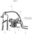
- FIG. 7 is a view illustrating the refrigerant circulating configuration in the refrigerant circuit for the chiller when the chiller is turned-on according to an exemplary embodiment of the present disclosure
- FIG. 8 is a conceptual view of an entire system illustrated in FIG. 7 according to an exemplary embodiment of the present disclosure.
- FIG. 9 is a structural view of the chiller according to an exemplary embodiment of the present disclosure.
- FIG. 10 shows the chiller according to a first exemplary embodiment of the present disclosure and is a cross-sectional view taken along line A-A of FIG. 9 ;
- FIG. 11 shows the chiller according to a second exemplary embodiment of the present disclosure and is a cross-sectional view taken along line A-A of FIG. 9 .
- vehicle or “vehicular” or other similar term as used herein is inclusive of motor vehicles in general such as passenger automobiles including sports utility vehicles (SUV), buses, trucks, various commercial vehicles, watercraft including a variety of boats and ships, aircraft, and the like, and includes hybrid vehicles, electric vehicles, plug-in hybrid electric vehicles, hydrogen-powered vehicles and other alternative fuel vehicles (e.g. fuels derived from resources other than petroleum).
- a hybrid vehicle is a vehicle that has two or more sources of power, for example both gasoline-powered and electric-powered vehicles.
- controller/control unit refers to a hardware device that includes a memory and a processor.
- the memory is configured to store the modules and the processor is specifically configured to execute said modules to perform one or more processes which are described further below.
- control logic of the present disclosure may be embodied as non-transitory computer readable media on a computer readable medium containing executable program instructions executed by a processor, controller/control unit or the like.
- the computer readable mediums include, but are not limited to, ROM, RAM, compact disc (CD)-ROMs, magnetic tapes, floppy disks, flash drives, smart cards and optical data storage devices.
- the computer readable recording medium can also be distributed in network coupled computer systems so that the computer readable media is stored and executed in a distributed fashion, e.g., by a telematics server or a Controller Area Network (CAN).
- a telematics server or a Controller Area Network (CAN).
- CAN Controller Area Network
- the present disclosure relates to a water-cooling type battery cooling system and a cooling method using the same, and more particularly, to a cooling system, in which a refrigerant circuit for enhancing cooling and discharge temperature control is provided, in a water-cooling battery cooling system for cooling a battery using an air conditioner system, and a cooling method using the same.
- FIG. 3 an air conditioner system in which a water-cooling type battery cooling system according to the present disclosure is provided is illustrated.
- the water-cooling type battery cooling system of the present disclosure for cooling coolant using a refrigerant of an air conditioner system may include an evaporator 2 , a compressor 4 and a condenser 6 having a refrigerant circuit of the air conditioner system to cool a vehicle indoor space and a refrigerant circuit for a chiller to cool a battery, which are integrally formed with each other.
- the water-cooling type battery cooling system may further include a liquid pipe 26 together with a chiller 10 to which a suction pipe 8 separated from a battery coolant line may be connected.
- a refrigerant of the air conditioner system may flow from the evaporator 2 to the compressor through the suction pipe.
- a refrigerant discharged from the condenser 6 may flow in the liquid pipe 26 , and this refrigerant may be discharged from the condenser 6 and flow in the liquid pipe 26 , and the liquid pipe 26 may divide the flow amount of refrigerant into the flow amount of refrigerant entering the compressor 4 via the chiller 10 and the flow amount of refrigerant entering the evaporator 2 without passing through the chiller 10 .
- the evaporator 2 and the compressor 4 may be connected to each other via the suction pipe 8 directly connected thereto, and an internal refrigerant of the evaporator 2 may flow into the compressor 4 through the suction pipe 8 .
- the chiller 10 for cooling a battery and a thermostatic expansion valve 24 for the chiller may be mounted on a particular longitudinal portion of the suction pipe 8 .
- the suction piping 8 may be in communication with the chiller 10 and the thermostatic expansion valve 24 for the chiller.
- An internal refrigerant of the suction pipe 8 discharged from the evaporator 2 may pass through sequentially the thermostatic expansion valve 24 for the chiller and the chiller 10 , and subsequently may flow into the compressor 4 along the suction pipe 8 .
- a first end of the liquid pipe 26 may be connected to the condenser 6 and a second end of the liquid pipe 26 may be connected to the suction pipe 8 .
- a location where the liquid pipe 26 is connected to the suction 8 may be between the thermostatic expansion valve 24 for the chiller and the evaporator 2 .
- the refrigerant discharged from the condenser 6 may flow along the liquid pipe 26 and flow into the suction pipe 8 .
- An internal refrigerant of the liquid pipe 26 flowing into the suction pipe 8 may be coalesced with the internal refrigerant of the suction pipe 8 .
- the chiller 10 for cooling the battery may include a chiller suction inlet port 12 into which the internal refrigerant of the suction pipe 8 may flow, a chiller liquid inlet port 14 into which the internal refrigerant of the liquid pipe 26 may flow, and a refrigerant outlet port 16 through which an internal refrigerant of the chiller 10 entered through the chiller suction inlet port 12 and the chiller liquid inlet port 14 may be discharged.
- the chiller suction inlet port 12 and the refrigerant outlet out 16 may be coaxially formed with each other, and the refrigerant outlet port 16 may be connected to the suction pipe 8 that extends toward the compressor 4 .
- a coolant inlet port 20 and a coolant outlet port 22 may be formed in the chiller 10 .
- coolant for cooling the battery may flow into the coolant inlet port 20 and may be discharged from the coolant outlet port 22 .
- the thermal expansion valve 24 for the chiller may include a valve suction inlet port (not shown) into which the internal refrigerant of the suction pipe 8 may flow and a valve liquid inlet port (not shown) into which the internal refrigerant of the liquid pipe 26 may flow.
- the valve suction inlet port may be in communication with and coaxially formed with the chiller suction inlet port 12
- the valve liquid inlet port may be in communication with and coaxially formed with the chiller liquid inlet port 14 .
- the valve suction inlet port may be connected to the suction pipe 8 that extends from the evaporator 2 .
- the liquid pipe 26 may be formed to be in communication with the valve liquid inlet port at a particular longitudinal portion thereof.
- a solenoid valve 28 may provide communication between the liquid pipe 26 and the valve liquid inlet port.
- the solenoid valve 28 may be mounted in the thermostatic expansion valve 24 for the chiller, and the valve liquid inlet port may be opened or closed by operation of the solenoid valve 28 to control a communication between the liquid pipe 26 and the valve liquid inlet port.
- the solenoid valve 28 in which an orifice aperture is formed may be changed to an opened state when the turn-on signal is transmitted to the chiller 10 , and may be changed to a closed state when a turn-off signal is transmitted to the chiller 10 .
- FIG. 5 is a view illustrating a refrigerant circulating configuration in a refrigerant circuit for the chiller when the chiller is turned-off
- FIG. 6 illustrates a conceptual view of an entire system illustrated in FIG. 5
- the solenoid valve 28 may be maintained in a closed state, and thus, the liquid pipe 26 is not in communication with the valve liquid inlet port. Accordingly, the internal refrigerant of the liquid pipe 26 is not divided and does not flow into the valve liquid inlet port side, and thus may flow towards the suction pipe 8 connected to the second end of the liquid pipe 26 .
- a double pipe structure of the suction pipe 8 allows the refrigerant discharged from the liquid pipe 26 to flow towards the evaporator 2 without being mixed with the flow of refrigerant flowing from the evaporator 2 to the compressor 4 .
- FIG. 7 is a view illustrating the refrigerant circulating configuration in the refrigerant circuit for the chiller when the chiller is turned-on
- FIG. 8 is a conceptual view of an entire system illustrated in FIG. 7 .
- the solenoid valve 28 is opened when the turn-on signal is transmitted to the chiller 10
- the liquid pipe 26 is in communication with the valve liquid inlet port.
- the internal refrigerant of the liquid pipe 26 may be divided, a first portion of divided refrigerant may flow into the chiller 10 via the valve liquid inlet port and the chiller liquid inlet port 14 , and a second portion of divided refrigerant may flow towards the suction pipe 8 connected to the second end of the liquid pipe 26 .
- FIG. 9 shows a structural view of the chiller of the present disclosure
- FIG. 10 shows the chiller according to a first exemplary embodiment of the present disclosure and is a cross-sectional view taken along line A-A of FIG. 9 .
- the chiller 10 of the present disclosure has a cross section as illustrated in FIG. 10
- the internal refrigerant of the suction pipe 8 flowing into the chiller 10 through the chiller suction inlet port 12 is not circulated in the chiller 10 , but may be discharged into the suction pipe 8 , connected to the compressor 4 , through the refrigerant outlet port 16 .
- the internal refrigerant of the liquid pipe 26 flowing into the chiller 10 through the chiller liquid inlet port 14 may be circulated in the chiller 10 and heat-exchanged to cool coolant for the battery in the chiller 10 .
- FIG. 11 shows the chiller according to a second exemplary embodiment of the present disclosure and is a cross-sectional view taken along line A-A of FIG. 9 .
- a partition 18 that closes a space between the chiller suction inlet port 12 and the refrigerant outlet port 16 is provided in the chiller 10 of the present disclosure as illustrated in FIG. 11 , the internal refrigerant of the suction pipe 8 flowing into the chiller 10 through the chiller suction inlet port 12 is not directly discharged through the refrigerant outlet port 16 , but may be circulated in the chiller 10 and heat-exchanged to cool coolant for the battery in the chiller 10 .
- the internal refrigerant of the liquid pipe 26 flowing into the chiller 10 through the chiller liquid inlet port 14 may be coalesced with the internal refrigerant of the suction pipe 8 in the chiller 10 , and may be circulated in the chiller 10 and heat-exchanged to cool coolant for the battery in the chiller 10 .
- the cooling method using the water-cooling type battery cooling system of the present disclosure configured as described above disclosure may include transmitting a turn-on signal to the chiller 10 for cooling the battery; operating the solenoid valve 28 mounted in the thermostatic expansion valve 24 for the chiller to open the valve liquid inlet port; dividing the internal refrigerant of the liquid pipe 26 to allow a first portion of divided refrigerant to be directed towards the valve liquid inlet port and to flow into the chiller; circulating the internal refrigerant of the liquid pipe 26 flowing into the chiller 20 to be heat-exchanged and to cool coolant for the battery in the chiller 10 ; and discharging the internal refrigerant of the liquid pipe 26 , which has cooled coolant for the battery in the chiller 10 , via the refrigerant discharge port 16 .
- the valve liquid inlet port Before the turn-on signal is transmitted to the chiller 10 , the valve liquid inlet port may be maintained in a closed state by the solenoid valve 28 , and the internal refrigerant of the liquid pipe 26 discharged from the condenser 6 may flow towards the suction pipe 8 connected to the second end of the liquid pipe 26 .
- the solenoid valve 28 When the turn-on signal is transmitted to the chiller 10 to cool the battery, the solenoid valve 28 may be operated to allow the valve liquid inlet port to be in communication with the liquid pipe 26 .
- the internal refrigerant of the liquid pipe 26 may be divided, and thus, some of the divided refrigerant may flow towards the valve liquid inlet port and into the chiller 10 , and some other refrigerant may flow towards the suction pipe 8 .
- the internal refrigerant of the liquid pipe 26 flowing into the chiller 10 may be circulated in the chiller 10 and heat-exchanged to cool coolant for cooling the battery in the chiller 10 . This refrigerant may then be discharged to the outside of the chiller 10 via the refrigerant outlet port 16 .
- the internal refrigerant of the suction pipe 8 which passes sequentially through the chiller suction inlet port 12 and the refrigerant outlet port 16 , may flow into the chiller 10 .
- the internal refrigerant of the liquid pipe 26 may be coalesced with the internal refrigerant of the suction pipe 8 in the chiller 10 and then may be discharged to the outside of the chiller 10 , and the internal refrigerant of the liquid pipe 26 discharged to the outside of the chiller 10 may flow into the compressor 4 .
- the internal refrigerant of the suction pipe 8 always passes through the inside of the chiller 10 regardless whether the chiller 10 is turned-on or turned-off, when the battery cooling condition is in a mild state, it may be possible to cool the battery using the internal refrigerant of the suction pipe 8 without dividing the internal refrigerant of the liquid pipe 26 and flowing into the chiller 10 . Therefore, it may be possible to prevent a problem in which indoor space cooling performance is deteriorated due to a sudden change in the flow amount distribution of the refrigerant, which has been a problem in the air conditioner system in which the internal refrigerant of the existing liquid pipe is divided to cool the battery.
- the structure of the system may be simplified to optimize the inner space of an engine compartment, thereby reducing the cost and weight, and improving the ability to be assembled.
Landscapes
- Engineering & Computer Science (AREA)
- Manufacturing & Machinery (AREA)
- Chemical & Material Sciences (AREA)
- Chemical Kinetics & Catalysis (AREA)
- Electrochemistry (AREA)
- General Chemical & Material Sciences (AREA)
- Physics & Mathematics (AREA)
- Thermal Sciences (AREA)
- Mechanical Engineering (AREA)
- Automation & Control Theory (AREA)
- Secondary Cells (AREA)
Abstract
Description
Claims (12)
Priority Applications (1)
| Application Number | Priority Date | Filing Date | Title |
|---|---|---|---|
| US17/177,817 US11724559B2 (en) | 2018-07-24 | 2021-02-17 | Water-cooling type battery cooling system and cooling method using the same |
Applications Claiming Priority (2)
| Application Number | Priority Date | Filing Date | Title |
|---|---|---|---|
| KR1020180085912A KR102621904B1 (en) | 2018-07-24 | 2018-07-24 | Water-cooled battery cooling system and cooling method using the same |
| KR10-2018-0085912 | 2018-07-24 |
Related Child Applications (1)
| Application Number | Title | Priority Date | Filing Date |
|---|---|---|---|
| US17/177,817 Division US11724559B2 (en) | 2018-07-24 | 2021-02-17 | Water-cooling type battery cooling system and cooling method using the same |
Publications (2)
| Publication Number | Publication Date |
|---|---|
| US20200031192A1 US20200031192A1 (en) | 2020-01-30 |
| US10953722B2 true US10953722B2 (en) | 2021-03-23 |
Family
ID=69177761
Family Applications (2)
| Application Number | Title | Priority Date | Filing Date |
|---|---|---|---|
| US16/205,311 Active 2039-03-16 US10953722B2 (en) | 2018-07-24 | 2018-11-30 | Water-cooling type battery cooling system and cooling method using the same |
| US17/177,817 Active 2039-01-29 US11724559B2 (en) | 2018-07-24 | 2021-02-17 | Water-cooling type battery cooling system and cooling method using the same |
Family Applications After (1)
| Application Number | Title | Priority Date | Filing Date |
|---|---|---|---|
| US17/177,817 Active 2039-01-29 US11724559B2 (en) | 2018-07-24 | 2021-02-17 | Water-cooling type battery cooling system and cooling method using the same |
Country Status (3)
| Country | Link |
|---|---|
| US (2) | US10953722B2 (en) |
| KR (1) | KR102621904B1 (en) |
| CN (1) | CN110752419B (en) |
Families Citing this family (3)
| Publication number | Priority date | Publication date | Assignee | Title |
|---|---|---|---|---|
| US11754204B2 (en) | 2020-07-27 | 2023-09-12 | Hanon Systems | Stabilized h-plate |
| CN112020289A (en) * | 2020-09-23 | 2020-12-01 | 深圳杰微芯片科技有限公司 | Equipment water-cooling system based on Internet of things |
| KR102357139B1 (en) | 2021-09-29 | 2022-02-08 | 주식회사 케이알엔지니어링 | Structure for cooling of explosion-proof type battery room |
Citations (9)
| Publication number | Priority date | Publication date | Assignee | Title |
|---|---|---|---|---|
| US20090249807A1 (en) | 2008-04-04 | 2009-10-08 | Gm Global Technology Operations, Inc. | HVAC and Battery Thermal Management for a Vehicle |
| US20110146266A1 (en) * | 2008-06-16 | 2011-06-23 | Marcus Weinbrenner | Device for cooling a coolant, circuit for charging an internal combustion engine, and method for cooling a substantially gaseous charging fluid for charging an internal combustion engine |
| US20120297809A1 (en) | 2011-05-26 | 2012-11-29 | Neil Carpenter | Refrigerant loop for battery electric vehicle with internal heat exchanger for heat exchange with coolant |
| US20130061630A1 (en) * | 2011-08-31 | 2013-03-14 | Bernd Schaefer | Heat exchanger |
| US20170088006A1 (en) | 2015-09-24 | 2017-03-30 | Ford Global Technologies, Llc | Hybrid vehicle with combined cabin and battery cooling |
| US20170158081A1 (en) | 2015-12-08 | 2017-06-08 | Hyundai Motor Company | Battery cooling system for a vehicle |
| US20170217279A1 (en) | 2016-01-29 | 2017-08-03 | Ford Global Technologies, Llc | Vehicle cabin air conditioning and battery cooling system |
| US20170297407A1 (en) | 2016-04-15 | 2017-10-19 | Denso International America, Inc. | Cooling System for Vehicle Battery Pack |
| US20170313158A1 (en) | 2016-04-29 | 2017-11-02 | Ford Global Technologies, Llc | Traction battery cooling system for an electrified vehicle |
Family Cites Families (13)
| Publication number | Priority date | Publication date | Assignee | Title |
|---|---|---|---|---|
| NO2133572T3 (en) * | 2008-06-12 | 2018-04-14 | ||
| KR101128531B1 (en) * | 2009-11-30 | 2012-03-27 | 기아자동차주식회사 | Liquid supercooling system |
| DE102010042122B4 (en) * | 2010-10-07 | 2019-02-28 | Audi Ag | Cooling device of a vehicle |
| KR101436960B1 (en) * | 2012-11-20 | 2014-09-16 | 대한칼소닉주식회사 | Electric vehicle battery temperature management system conjunction with the HVAC system and its operating method |
| WO2014117017A1 (en) * | 2013-01-25 | 2014-07-31 | Trane International Inc. | Capacity modulating an expansion device of a hvac system |
| DE102014204935A1 (en) * | 2014-03-17 | 2015-10-01 | Mahle International Gmbh | Heizkühlmodul |
| JP5843024B1 (en) | 2014-08-22 | 2016-01-13 | 大日本印刷株式会社 | Display device |
| KR101628120B1 (en) * | 2014-10-20 | 2016-06-08 | 현대자동차 주식회사 | Betterly cooling system for vehicle |
| US10573940B2 (en) * | 2015-02-25 | 2020-02-25 | Ford Global Technologies, Llc | Battery thermal management system |
| KR102364987B1 (en) * | 2015-07-27 | 2022-02-21 | 한온시스템 주식회사 | Battery cooling system for vehicle |
| KR102523026B1 (en) * | 2016-02-05 | 2023-04-19 | 한온시스템 주식회사 | Thermal management system of battery for vehicle |
| US10297880B2 (en) * | 2016-04-20 | 2019-05-21 | Ford Global Technologies, Llc | Battery thermal management system |
| KR20180062639A (en) * | 2016-12-01 | 2018-06-11 | 현대자동차주식회사 | Cooling-heating system by water cooled type for vehicle |
-
2018
- 2018-07-24 KR KR1020180085912A patent/KR102621904B1/en active Active
- 2018-11-30 US US16/205,311 patent/US10953722B2/en active Active
- 2018-12-06 CN CN201811486281.0A patent/CN110752419B/en active Active
-
2021
- 2021-02-17 US US17/177,817 patent/US11724559B2/en active Active
Patent Citations (9)
| Publication number | Priority date | Publication date | Assignee | Title |
|---|---|---|---|---|
| US20090249807A1 (en) | 2008-04-04 | 2009-10-08 | Gm Global Technology Operations, Inc. | HVAC and Battery Thermal Management for a Vehicle |
| US20110146266A1 (en) * | 2008-06-16 | 2011-06-23 | Marcus Weinbrenner | Device for cooling a coolant, circuit for charging an internal combustion engine, and method for cooling a substantially gaseous charging fluid for charging an internal combustion engine |
| US20120297809A1 (en) | 2011-05-26 | 2012-11-29 | Neil Carpenter | Refrigerant loop for battery electric vehicle with internal heat exchanger for heat exchange with coolant |
| US20130061630A1 (en) * | 2011-08-31 | 2013-03-14 | Bernd Schaefer | Heat exchanger |
| US20170088006A1 (en) | 2015-09-24 | 2017-03-30 | Ford Global Technologies, Llc | Hybrid vehicle with combined cabin and battery cooling |
| US20170158081A1 (en) | 2015-12-08 | 2017-06-08 | Hyundai Motor Company | Battery cooling system for a vehicle |
| US20170217279A1 (en) | 2016-01-29 | 2017-08-03 | Ford Global Technologies, Llc | Vehicle cabin air conditioning and battery cooling system |
| US20170297407A1 (en) | 2016-04-15 | 2017-10-19 | Denso International America, Inc. | Cooling System for Vehicle Battery Pack |
| US20170313158A1 (en) | 2016-04-29 | 2017-11-02 | Ford Global Technologies, Llc | Traction battery cooling system for an electrified vehicle |
Also Published As
| Publication number | Publication date |
|---|---|
| KR102621904B1 (en) | 2024-01-05 |
| KR20200011150A (en) | 2020-02-03 |
| CN110752419B (en) | 2024-04-30 |
| US11724559B2 (en) | 2023-08-15 |
| US20200031192A1 (en) | 2020-01-30 |
| US20210162836A1 (en) | 2021-06-03 |
| CN110752419A (en) | 2020-02-04 |
Similar Documents
| Publication | Publication Date | Title |
|---|---|---|
| US11724559B2 (en) | Water-cooling type battery cooling system and cooling method using the same | |
| US9242532B2 (en) | Air conditioner system control method for vehicle | |
| CN110758047B (en) | Heating and cooling systems for vehicles | |
| US8631889B2 (en) | Combined condensation radiator fan module and brake cooling duct shutter system | |
| US9809086B2 (en) | Method and system for controlling vehicle radiator flap | |
| US10486495B2 (en) | Method and system to manage vehicle thermal conditions | |
| US11065935B2 (en) | Thermal management system for electric vehicle | |
| US11390135B2 (en) | Thermal management system for vehicle | |
| US20150096313A1 (en) | System off configuration for climate control system | |
| US20210023909A1 (en) | Hvac system of vehicle | |
| KR20210079741A (en) | Automotive air conditioning system | |
| US20200171917A1 (en) | Vehicular air conditioning system and method for controlling the same | |
| US20200335838A1 (en) | Device for cooling a battery | |
| US20250065693A1 (en) | Integrated thermal management circuit for vehicle | |
| US20100175406A1 (en) | Auxiliary Battery Cooling for a Vehicle | |
| US20220115930A1 (en) | System for overcooling drive motor and method for controlling the same | |
| US10538214B2 (en) | Controlled in-tank flow guide for heat exchanger | |
| US20200338955A1 (en) | Thermal management system for electric vehicle | |
| US10605503B2 (en) | Condensate enhanced subcooler | |
| CN110978936A (en) | Method and apparatus for split-flow chiller | |
| US10365027B2 (en) | Simplified and energy efficient multi temperature unit | |
| US20170326940A1 (en) | Individual air conditioning apparatus for vehicle and method of controlling the same | |
| US12311724B2 (en) | HVAC system | |
| EP1623857A1 (en) | HVAC Systems | |
| EP4301104A1 (en) | Electronic system for an industrial vehicle |
Legal Events
| Date | Code | Title | Description |
|---|---|---|---|
| AS | Assignment |
Owner name: HYUNDAI MOTOR COMPANY, KOREA, REPUBLIC OF Free format text: ASSIGNMENT OF ASSIGNORS INTEREST;ASSIGNORS:CHA, YONG-WOONG;PARK, JUNG-HA;YUN, JOONG-SU;SIGNING DATES FROM 20181024 TO 20181029;REEL/FRAME:048172/0592 Owner name: KIA MOTORS CORPORATION, KOREA, REPUBLIC OF Free format text: ASSIGNMENT OF ASSIGNORS INTEREST;ASSIGNORS:CHA, YONG-WOONG;PARK, JUNG-HA;YUN, JOONG-SU;SIGNING DATES FROM 20181024 TO 20181029;REEL/FRAME:048172/0592 |
|
| FEPP | Fee payment procedure |
Free format text: ENTITY STATUS SET TO UNDISCOUNTED (ORIGINAL EVENT CODE: BIG.); ENTITY STATUS OF PATENT OWNER: LARGE ENTITY |
|
| AS | Assignment |
Owner name: KIA MOTORS CORPORATION, KOREA, REPUBLIC OF Free format text: ASSIGNMENT OF ASSIGNORS INTEREST;ASSIGNORS:CHA, YONG-WOONG;PARK, JUNG-HA;YUN, JOONG-SU;REEL/FRAME:047864/0547 Effective date: 20181029 Owner name: HYUNDAI MOTOR COMPANY, KOREA, REPUBLIC OF Free format text: ASSIGNMENT OF ASSIGNORS INTEREST;ASSIGNORS:CHA, YONG-WOONG;PARK, JUNG-HA;YUN, JOONG-SU;REEL/FRAME:047864/0547 Effective date: 20181029 |
|
| STPP | Information on status: patent application and granting procedure in general |
Free format text: NON FINAL ACTION MAILED |
|
| STPP | Information on status: patent application and granting procedure in general |
Free format text: RESPONSE TO NON-FINAL OFFICE ACTION ENTERED AND FORWARDED TO EXAMINER |
|
| STPP | Information on status: patent application and granting procedure in general |
Free format text: RESPONSE TO NON-FINAL OFFICE ACTION ENTERED AND FORWARDED TO EXAMINER |
|
| STCF | Information on status: patent grant |
Free format text: PATENTED CASE |
|
| MAFP | Maintenance fee payment |
Free format text: PAYMENT OF MAINTENANCE FEE, 4TH YEAR, LARGE ENTITY (ORIGINAL EVENT CODE: M1551); ENTITY STATUS OF PATENT OWNER: LARGE ENTITY Year of fee payment: 4 |