US10951000B2 - High power single mode fiber laser - Google Patents
High power single mode fiber laser Download PDFInfo
- Publication number
- US10951000B2 US10951000B2 US15/764,147 US201615764147A US10951000B2 US 10951000 B2 US10951000 B2 US 10951000B2 US 201615764147 A US201615764147 A US 201615764147A US 10951000 B2 US10951000 B2 US 10951000B2
- Authority
- US
- United States
- Prior art keywords
- fiber
- output
- passive
- high power
- light
- Prior art date
- Legal status (The legal status is an assumption and is not a legal conclusion. Google has not performed a legal analysis and makes no representation as to the accuracy of the status listed.)
- Active, expires
Links
- 239000000835 fiber Substances 0.000 title claims abstract description 128
- 230000009022 nonlinear effect Effects 0.000 claims abstract description 3
- 238000001069 Raman spectroscopy Methods 0.000 abstract description 2
- 230000003287 optical effect Effects 0.000 description 3
- 230000003247 decreasing effect Effects 0.000 description 2
- 238000012545 processing Methods 0.000 description 2
- 238000013459 approach Methods 0.000 description 1
- 238000005253 cladding Methods 0.000 description 1
- 230000000694 effects Effects 0.000 description 1
- 230000005284 excitation Effects 0.000 description 1
- 238000001914 filtration Methods 0.000 description 1
- 230000003993 interaction Effects 0.000 description 1
- 239000000463 material Substances 0.000 description 1
- 238000005459 micromachining Methods 0.000 description 1
- 238000012986 modification Methods 0.000 description 1
- 230000004048 modification Effects 0.000 description 1
- 230000001902 propagating effect Effects 0.000 description 1
- 239000010453 quartz Substances 0.000 description 1
- 230000005855 radiation Effects 0.000 description 1
- VYPSYNLAJGMNEJ-UHFFFAOYSA-N silicon dioxide Inorganic materials O=[Si]=O VYPSYNLAJGMNEJ-UHFFFAOYSA-N 0.000 description 1
- 238000012360 testing method Methods 0.000 description 1
- 238000003466 welding Methods 0.000 description 1
Images


Classifications
-
- H—ELECTRICITY
- H01—ELECTRIC ELEMENTS
- H01S—DEVICES USING THE PROCESS OF LIGHT AMPLIFICATION BY STIMULATED EMISSION OF RADIATION [LASER] TO AMPLIFY OR GENERATE LIGHT; DEVICES USING STIMULATED EMISSION OF ELECTROMAGNETIC RADIATION IN WAVE RANGES OTHER THAN OPTICAL
- H01S3/00—Lasers, i.e. devices using stimulated emission of electromagnetic radiation in the infrared, visible or ultraviolet wave range
- H01S3/005—Optical devices external to the laser cavity, specially adapted for lasers, e.g. for homogenisation of the beam or for manipulating laser pulses, e.g. pulse shaping
-
- B—PERFORMING OPERATIONS; TRANSPORTING
- B23—MACHINE TOOLS; METAL-WORKING NOT OTHERWISE PROVIDED FOR
- B23K—SOLDERING OR UNSOLDERING; WELDING; CLADDING OR PLATING BY SOLDERING OR WELDING; CUTTING BY APPLYING HEAT LOCALLY, e.g. FLAME CUTTING; WORKING BY LASER BEAM
- B23K26/00—Working by laser beam, e.g. welding, cutting or boring
- B23K26/02—Positioning or observing the workpiece, e.g. with respect to the point of impact; Aligning, aiming or focusing the laser beam
- B23K26/06—Shaping the laser beam, e.g. by masks or multi-focusing
- B23K26/064—Shaping the laser beam, e.g. by masks or multi-focusing by means of optical elements, e.g. lenses, mirrors or prisms
-
- B—PERFORMING OPERATIONS; TRANSPORTING
- B23—MACHINE TOOLS; METAL-WORKING NOT OTHERWISE PROVIDED FOR
- B23K—SOLDERING OR UNSOLDERING; WELDING; CLADDING OR PLATING BY SOLDERING OR WELDING; CUTTING BY APPLYING HEAT LOCALLY, e.g. FLAME CUTTING; WORKING BY LASER BEAM
- B23K26/00—Working by laser beam, e.g. welding, cutting or boring
- B23K26/20—Bonding
- B23K26/21—Bonding by welding
-
- B—PERFORMING OPERATIONS; TRANSPORTING
- B23—MACHINE TOOLS; METAL-WORKING NOT OTHERWISE PROVIDED FOR
- B23K—SOLDERING OR UNSOLDERING; WELDING; CLADDING OR PLATING BY SOLDERING OR WELDING; CUTTING BY APPLYING HEAT LOCALLY, e.g. FLAME CUTTING; WORKING BY LASER BEAM
- B23K26/00—Working by laser beam, e.g. welding, cutting or boring
- B23K26/36—Removing material
-
- G—PHYSICS
- G02—OPTICS
- G02B—OPTICAL ELEMENTS, SYSTEMS OR APPARATUS
- G02B6/00—Light guides; Structural details of arrangements comprising light guides and other optical elements, e.g. couplings
- G02B6/24—Coupling light guides
- G02B6/42—Coupling light guides with opto-electronic elements
- G02B6/4201—Packages, e.g. shape, construction, internal or external details
- G02B6/4204—Packages, e.g. shape, construction, internal or external details the coupling comprising intermediate optical elements, e.g. lenses, holograms
- G02B6/421—Packages, e.g. shape, construction, internal or external details the coupling comprising intermediate optical elements, e.g. lenses, holograms the intermediate optical component consisting of a short length of fibre, e.g. fibre stub
-
- G—PHYSICS
- G02—OPTICS
- G02B—OPTICAL ELEMENTS, SYSTEMS OR APPARATUS
- G02B6/00—Light guides; Structural details of arrangements comprising light guides and other optical elements, e.g. couplings
- G02B6/24—Coupling light guides
- G02B6/42—Coupling light guides with opto-electronic elements
- G02B6/4296—Coupling light guides with opto-electronic elements coupling with sources of high radiant energy, e.g. high power lasers, high temperature light sources
-
- H—ELECTRICITY
- H01—ELECTRIC ELEMENTS
- H01S—DEVICES USING THE PROCESS OF LIGHT AMPLIFICATION BY STIMULATED EMISSION OF RADIATION [LASER] TO AMPLIFY OR GENERATE LIGHT; DEVICES USING STIMULATED EMISSION OF ELECTROMAGNETIC RADIATION IN WAVE RANGES OTHER THAN OPTICAL
- H01S3/00—Lasers, i.e. devices using stimulated emission of electromagnetic radiation in the infrared, visible or ultraviolet wave range
- H01S3/05—Construction or shape of optical resonators; Accommodation of active medium therein; Shape of active medium
- H01S3/06—Construction or shape of active medium
- H01S3/063—Waveguide lasers, i.e. whereby the dimensions of the waveguide are of the order of the light wavelength
- H01S3/067—Fibre lasers
- H01S3/06708—Constructional details of the fibre, e.g. compositions, cross-section, shape or tapering
- H01S3/06745—Tapering of the fibre, core or active region
-
- H—ELECTRICITY
- H01—ELECTRIC ELEMENTS
- H01S—DEVICES USING THE PROCESS OF LIGHT AMPLIFICATION BY STIMULATED EMISSION OF RADIATION [LASER] TO AMPLIFY OR GENERATE LIGHT; DEVICES USING STIMULATED EMISSION OF ELECTROMAGNETIC RADIATION IN WAVE RANGES OTHER THAN OPTICAL
- H01S3/00—Lasers, i.e. devices using stimulated emission of electromagnetic radiation in the infrared, visible or ultraviolet wave range
- H01S3/05—Construction or shape of optical resonators; Accommodation of active medium therein; Shape of active medium
- H01S3/06—Construction or shape of active medium
- H01S3/063—Waveguide lasers, i.e. whereby the dimensions of the waveguide are of the order of the light wavelength
- H01S3/067—Fibre lasers
- H01S3/06754—Fibre amplifiers
-
- H—ELECTRICITY
- H01—ELECTRIC ELEMENTS
- H01S—DEVICES USING THE PROCESS OF LIGHT AMPLIFICATION BY STIMULATED EMISSION OF RADIATION [LASER] TO AMPLIFY OR GENERATE LIGHT; DEVICES USING STIMULATED EMISSION OF ELECTROMAGNETIC RADIATION IN WAVE RANGES OTHER THAN OPTICAL
- H01S3/00—Lasers, i.e. devices using stimulated emission of electromagnetic radiation in the infrared, visible or ultraviolet wave range
- H01S3/30—Lasers, i.e. devices using stimulated emission of electromagnetic radiation in the infrared, visible or ultraviolet wave range using scattering effects, e.g. stimulated Brillouin or Raman effects
- H01S3/302—Lasers, i.e. devices using stimulated emission of electromagnetic radiation in the infrared, visible or ultraviolet wave range using scattering effects, e.g. stimulated Brillouin or Raman effects in an optical fibre
-
- G—PHYSICS
- G02—OPTICS
- G02B—OPTICAL ELEMENTS, SYSTEMS OR APPARATUS
- G02B6/00—Light guides; Structural details of arrangements comprising light guides and other optical elements, e.g. couplings
- G02B6/24—Coupling light guides
- G02B6/241—Light guide terminations
-
- H—ELECTRICITY
- H01—ELECTRIC ELEMENTS
- H01S—DEVICES USING THE PROCESS OF LIGHT AMPLIFICATION BY STIMULATED EMISSION OF RADIATION [LASER] TO AMPLIFY OR GENERATE LIGHT; DEVICES USING STIMULATED EMISSION OF ELECTROMAGNETIC RADIATION IN WAVE RANGES OTHER THAN OPTICAL
- H01S3/00—Lasers, i.e. devices using stimulated emission of electromagnetic radiation in the infrared, visible or ultraviolet wave range
- H01S3/05—Construction or shape of optical resonators; Accommodation of active medium therein; Shape of active medium
- H01S3/06—Construction or shape of active medium
- H01S3/0602—Crystal lasers or glass lasers
- H01S3/0604—Crystal lasers or glass lasers in the form of a plate or disc
Definitions
- This disclosure relates to high power single mode (SM) fiber lasers with a double-bottleneck shaped delivery fiber configured to deliver laser light to remote locations.
- SM single mode
- SRS stimulated Raman scattering
- NLE nonlinear effect
- a eff is the effective mode area of the fiber
- L is the fiber length.
- the fibers disclosed in '272 constitute a fiber block which includes at least an active fiber and output passive fiber, and the system, operating in a continuous wave (CW) regime, may have one or more of such fiber blocks to reach tens of kW at the output of the delivery fiber.
- CW continuous wave
- the system operating in a continuous wave (CW) regime, may have one or more of such fiber blocks to reach tens of kW at the output of the delivery fiber.
- CW continuous wave
- the inventive SM, high power fiber laser configured with a light source, which emits SM, kW-level light, and a multi-meter delivery fiber, i.e., the fiber (aka as feeding fiber) delivering light to a laser head or directly from the laser head to the workpiece to be laser treated or both, that outputs the emitted light having an M 2 value of less than 2.
- the inventive delivery fiber has the length varying between about 2 and 20 meters, with the 20 m long fiber being used in a 1 kW fiber laser system.
- the disclosed delivery fiber outputs the light with an M 2 value of about 1.05 which is substantially lower than the same laser systems equipped with regular cylindrical fibers.
- the delivery fiber is configured with a monolithic core having a double bottle neck cross-section which suppresses the onset of SRS.
- the length of the delivery fiber configured in accordance with the invention is at least twice as long as a standard, uniformly configured delivery fiber, provided both types of the delivery fiber are used with the same system having the same parameters.
- FIG. 1 is an overall view of the disclosed SM fiber laser system
- FIG. 2 is one embodiment of the disclosed delivery fiber of FIG. 1 ;
- FIG. 3 is another embodiment of the disclosed delivery fiber of FIG. 1 ;
- FIG. 4A is a computer generated view illustrating the quality of light at the output of the system of FIG. 1 configured with a standard delivery fiber;
- FIG. 4B is a computer generated view illustrating the quality of light at the output of the system of FIG. 1 with the disclosed delivery fiber.
- a high power single mode fiber laser system 10 is operative to continuously output radiation in a single mode or low modes with an M 2 value of at most equal to 2, but preferably lower than 1.5 and even lower than 1.1.
- the SM fiber laser system 10 may be configured with a laser source configured either as a fiber laser or disc laser.
- a laser source configured either as a fiber laser or disc laser.
- the system 10 thus includes a seed 12 outputting signal light which propagates through a fiber length including at least one amplifying stage which is configured with an input SM passive fiber 14 , active fiber 16 and output SM passive fiber 18 together constituting a fiber gain block GB.
- the active fiber 16 may have a cylindrical or bottleneck-shaped core.
- the increased number of gain blocks GB allows higher output powers. Therefore, the power range of the disclosed system is reasonably unlimited since several SM systems 10 can be combined together so that the system power may vary in a 1-50 kW power range and higher.
- the high power SM signal light emitted from the GB is coupled into a fiber 20 guiding the signal light to a processing laser head 32 which is typically configured with a housing enclosing necessary optics.
- LH 32 may be configured such that an additional delivery 22 is needed to guide light from the laser head to the workpiece to be treated WP.
- fiber 20 is referred to as a feeding fiber while fiber 22 is typically called a delivery fiber.
- both fibers 20 and 22 are referred to as the delivery fiber.
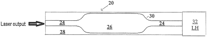
- a delivery fiber 20 (and fiber 22 ) has a monolithic double bottleneck-shaped core which includes input and output core sections 24 and central core section 26 , and either bottlenecked-shaped or cylindrically-shaped cladding 28 .
- the core is configured such that input and output core sections 24 respectively are dimensioned to support only the SM laser output received from output SM passive fiber 18 ( FIG. 1 ).
- the central core section 26 is provided with a substantially greater diameter than sections 24 , which allows central core section 26 to support multiple modes.
- the adiabatically expanding tapered sections 30 bridging the input and output sections with respective opposite ends of central section 26 complete the configuration of feed fiber 20 .
- the SM signal light propagating along input core section 24 is adiabatically expanded, along tapered section such that excitation of high order modes in central core section 26 is minimal and preferably nonexistent. Those high order modes that have been excited are further filtered out as the light propagates along the output tapered and end output core sections 30 and 24 , respectively.
- central section 26 allows a threshold for NLE in general and SRS in particular to increase. With the increased diameter, however, not only the length of delivery fiber 20 (and/or 22 ) is increased, but the M 2 factor of the output light, when comparing structures of respective FIGS. 4A and 4B to the customarily used uniformly-shaped delivery fibers, is markedly lower and power losses are substantially minimized.
- the following table clearly illustrates the advantages of fiber system 10 that are provided with the disclosed delivery fiber over the same system but with a delivery fiber having a uniformly shaped core.
- the objective of the present invention is attained without sacrificing the quality of light.
- the power of fiber laser systems is scaled up without sacrificing the quality of output light which was not possible in the near past but has become reality.
- Fiber laser systems of up to 10 kW were tested and found fully operational.
- the same fiber laser systems each had the output with M 2 factor incomparably higher than that with the disclosed delivery fiber.
- M 2 and power losses in laser systems provided with a standard delivery fiber were found to be practically nonoperational.
- gain block GB has the same basic configuration as shown in FIG. 1 regardless of the output power within a 1 to 50 kW range.
- LH 32 of FIGS. 1-3 also may be utilized with the GB operating in a 1 to 50 kW power range.
- FIGS. 4A and 4B illustrate respective computer generated screens illustrating the results which are obtained by testing a 10 KW SM fiber laser with standard and disclosed fibers, respectively.
- the M 2 factor obtained by means of standard fiber is 1.89 m. This value is substantially improved in case of the same laser system but provided with the disclosed delivery fiber which allows M 2 factor of 1.33 despite being substantially longer than the standard fiber.
- inventive system 10 may also have a beam expander (not shown) coupled to the downstream end of the delivery fiber.
- the beam expander is made from quartz and configured to lower the power density of the output light before it is launched into laser head.
- inventive feed fiber may be used to deliver pulsed light.
Landscapes
- Physics & Mathematics (AREA)
- Optics & Photonics (AREA)
- Engineering & Computer Science (AREA)
- Electromagnetism (AREA)
- Plasma & Fusion (AREA)
- Mechanical Engineering (AREA)
- General Physics & Mathematics (AREA)
- Lasers (AREA)
- Laser Beam Processing (AREA)
- Optical Couplings Of Light Guides (AREA)
Abstract
A single mode (SM) high power laser system is configured with a laser source outputting a single mode or low mode kW-power light and a passive delivery fiber spliced to an output fiber of the fiber laser source and having a double bottleneck-shaped core. The latter is configured to increase a threshold for nonlinear effects in general and in particular for stimulated Raman scattering (SRS) so that the delivery passive fiber has a fiber length at least twice the length of a delivery passive fiber with a standard uniformly dimensioned core, which may be used with the same laser source, while outputting the kW-power light with an M2 factor less than 2.
Description
This disclosure relates to high power single mode (SM) fiber lasers with a double-bottleneck shaped delivery fiber configured to deliver laser light to remote locations.
High power, high brightness fiber sources are of great interest for various applications such as, among others, micro-machining, welding and material processing, and their output power has grown astronomically in recent years. However, power scaling with a single mode output beam quality, which requires a small core fiber, still remains a technological challenge, in the first instance because of the nonlinear scattering in the fiber. In particular, stimulated Raman scattering (SRS)—nonlinear effect (NLE)—is one of the main constraints on increasing the output power of a fiber based system and its length. Generally, the SRS threshold power Pth is determined as
Aeff is the effective mode area of the fiber, and L is the fiber length. Thus, in order to raise a threshold for nonlinear effects including SRS, a large core and a short fiber length are two of the obvious choices that work by reducing the optical power density in the doped-core and the interaction length of the optical field along the fiber.
As the core diameter becomes larger, the power density lowers and NLE threshold increases. With the latter, power handling capabilities of fiber laser improve. However, the core supports the SM only if its diameter does not exceed a certain limit after which the excitement of higher order modes cannot be prevented. A single mode output can still be obtained using an over the limit large core fiber with filtering of higher order mode, e.g., with a fiber taper. For example, U.S. Pat. No. 8,781,272 ('272), incorporated here in its entirety by reference, discloses a monolithic optical non-micro-structured fiber configured with a multimode (“MM”) core which has a double bottleneck-shaped cross-section. Despite being MM, the core is capable of supporting substantially only a fundamental mode. The fibers disclosed in '272 constitute a fiber block which includes at least an active fiber and output passive fiber, and the system, operating in a continuous wave (CW) regime, may have one or more of such fiber blocks to reach tens of kW at the output of the delivery fiber. Operating in conditions requiring SM delivery fibers not exceeding 5 meters at 1 kW power, no appreciable power losses have been observed. However, once the SM delivery fiber, having a uniformly configured core, was used for delivering the laser output at a distance exceeding 5 meters even with such a relatively modest 1 kW power, the delivered light experienced high power losses and greatly decreased quality. As the recent work to decommission the Fukushima Daiichi nuclear power facility exemplifies, substantially greater lengths of the delivery fiber providing SM high power laser light beam are often necessary.
A need therefore exists for a high power SM fiber laser provided with a delivery fiber which while guiding light at a distance substantially greater than is currently available, does not detrimentally affect the quality of light and its power.
This need is satisfied by the inventive SM, high power fiber laser configured with a light source, which emits SM, kW-level light, and a multi-meter delivery fiber, i.e., the fiber (aka as feeding fiber) delivering light to a laser head or directly from the laser head to the workpiece to be laser treated or both, that outputs the emitted light having an M2 value of less than 2.
Depending on the power of the laser source ranging between 1 and 50 kW, the inventive delivery fiber has the length varying between about 2 and 20 meters, with the 20 m long fiber being used in a 1 kW fiber laser system. Despite the impressive length of the delivery fiber if compared to the currently known designs, the disclosed delivery fiber outputs the light with an M2 value of about 1.05 which is substantially lower than the same laser systems equipped with regular cylindrical fibers.
The delivery fiber is configured with a monolithic core having a double bottle neck cross-section which suppresses the onset of SRS. With a high threshold for NLE, the length of the delivery fiber configured in accordance with the invention, is at least twice as long as a standard, uniformly configured delivery fiber, provided both types of the delivery fiber are used with the same system having the same parameters.
The above and other features and advantages will become more readily apparent from the specific description of the present disclosure accompanied by the following drawings, in which:
Reference will now be made in detail to the disclosed system. Wherever possible, same or similar reference numerals are used in the drawings and the description to refer to the same or like parts or steps. The drawings are in simplified form being far from precise scale. For purposes of convenience and clarity only, the terms “connect,” “couple,” and similar terms with their inflectional morphemes do not necessarily denote direct and immediate connections, but also include connections through mediate elements or devices.
Referring to FIG. 1 a high power single mode fiber laser system 10 is operative to continuously output radiation in a single mode or low modes with an M2 value of at most equal to 2, but preferably lower than 1.5 and even lower than 1.1. The SM fiber laser system 10 may be configured with a laser source configured either as a fiber laser or disc laser. The following description discloses a fiber laser, but one of ordinary skill in the art readily recognizes that the invented delivery fiber can be used in combination with a disc laser source.
The system 10 thus includes a seed 12 outputting signal light which propagates through a fiber length including at least one amplifying stage which is configured with an input SM passive fiber 14, active fiber 16 and output SM passive fiber 18 together constituting a fiber gain block GB. The active fiber 16 may have a cylindrical or bottleneck-shaped core. The increased number of gain blocks GB allows higher output powers. Therefore, the power range of the disclosed system is reasonably unlimited since several SM systems 10 can be combined together so that the system power may vary in a 1-50 kW power range and higher. The high power SM signal light emitted from the GB is coupled into a fiber 20 guiding the signal light to a processing laser head 32 which is typically configured with a housing enclosing necessary optics. Sometimes, LH 32 may be configured such that an additional delivery 22 is needed to guide light from the laser head to the workpiece to be treated WP. Usually, fiber 20 is referred to as a feeding fiber while fiber 22 is typically called a delivery fiber. For the purposes of this disclosure, however, both fibers 20 and 22 are referred to as the delivery fiber.
As soon as the fiber laser industry realized the possibility of scaling SM fiber lasers, many efforts were directed to perfecting active fiber 16 and sometimes passive fibers 14, 18 constituting a gain block. Adhering to the main approach including increasing the core diameter and decreasing the fiber length, multi-kW powers in SM CW have been obtained due to the bottleneck-shaped active and passive fibers of the gain block. But delivery fiber 20 and/or 22 remains unaltered featuring a maximum uniform SM core diameter. In the past, to maintain an acceptable threshold for NILE in multi-kW systems with the desired M2 factor, a length of the delivery fiber was as short as possible. In contrast to the conventional wisdom, the inventive concept requires greater, not shorter, lengths of delivery fiber 20, 22.
Referring to FIGS. 2 and 3 , a delivery fiber 20 (and fiber 22) has a monolithic double bottleneck-shaped core which includes input and output core sections 24 and central core section 26, and either bottlenecked-shaped or cylindrically-shaped cladding 28. The core is configured such that input and output core sections 24 respectively are dimensioned to support only the SM laser output received from output SM passive fiber 18 (FIG. 1 ). However, the central core section 26 is provided with a substantially greater diameter than sections 24, which allows central core section 26 to support multiple modes. The adiabatically expanding tapered sections 30 bridging the input and output sections with respective opposite ends of central section 26 complete the configuration of feed fiber 20. The SM signal light propagating along input core section 24 is adiabatically expanded, along tapered section such that excitation of high order modes in central core section 26 is minimal and preferably nonexistent. Those high order modes that have been excited are further filtered out as the light propagates along the output tapered and end output core sections 30 and 24, respectively.
The increased diameter of central section 26 allows a threshold for NLE in general and SRS in particular to increase. With the increased diameter, however, not only the length of delivery fiber 20 (and/or 22) is increased, but the M2 factor of the output light, when comparing structures of respective FIGS. 4A and 4B to the customarily used uniformly-shaped delivery fibers, is markedly lower and power losses are substantially minimized. The following table clearly illustrates the advantages of fiber system 10 that are provided with the disclosed delivery fiber over the same system but with a delivery fiber having a uniformly shaped core.
| Max Length with | M2 | |||
| M2 | Max Length with | disclosed | disclosed | |
| Power | standard feed | standard delivery | delivery fiber | delivery |
| kW | fiber | fiber (m) | (m) | fiber |
| 1 | ~1.05 | 5 | 10-20 | ~1.05 | |
| 2 | NA | NA | 4 | ~1.1 | |
| 5 | NA | NA | 4 | ≤1.2 | |
| 10 | | NA | 2 | ≤1.5 | |
As can be seen, the objective of the present invention—greater lengths of delivery fiber—is attained without sacrificing the quality of light. Moreover, with the help of the disclosed delivery fiber, the power of fiber laser systems is scaled up without sacrificing the quality of output light which was not possible in the near past but has become reality. Fiber laser systems of up to 10 kW were tested and found fully operational. When used with a standard, cylindrically shaped delivery fiber, the same fiber laser systems each had the output with M2 factor incomparably higher than that with the disclosed delivery fiber. In fact, M2 and power losses in laser systems provided with a standard delivery fiber were found to be practically nonoperational.
Note that the gain block GB has the same basic configuration as shown in FIG. 1 regardless of the output power within a 1 to 50 kW range. Furthermore, LH 32 of FIGS. 1-3 also may be utilized with the GB operating in a 1 to 50 kW power range.
Returning to FIGS. 1-3 , inventive system 10 may also have a beam expander (not shown) coupled to the downstream end of the delivery fiber. The beam expander is made from quartz and configured to lower the power density of the output light before it is launched into laser head.
Although there has been illustrated and described in specific detail a structure of operations, it is clearly understood that the same were for purposes of illustration and that changes and modifications may be made readily therein by those skilled in the art without departing from the spirit and the scope of this invention. For example, the inventive feed fiber may be used to deliver pulsed light.
Claims (10)
1. A high power laser system, comprising:
a laser source outputting a single mode (SM) or low order mode kW-power light and having at least one fiber gain block which has an active fiber and an output SM passive fiber;
a passive delivery fiber spliced to the output SM passive fiber of the laser source and configured to have a double bottleneck-shaped core that is monolithic and includes:
an input end section receiving the kW power light from the laser source and an output end section, the input and output end sections each having a uniform diameter which is dimensioned to support the single mode;
a uniformly-dimensioned central section located between and having a diameter greater than that of each of the input and output end sections of the core, the central section of the core being dimensioned to support multiple modes; and
input and output tapered sections extending between respective opposite ends of the central section and the respective input and output end sections,
the passive delivery fiber increasing a threshold of nonlinear effects so that the passive delivery fiber has a fiber length at least twice the length in comparison to a length of a passive delivery fiber with a uniformly dimensioned core, while outputting the kW-power light with a beam quality factor M2 less than 2.
2. The high power laser system of claim 1 , wherein the laser source is configured to output the single mode or low order mode light in a power range varying between 1 kW and 50 kW.
3. The high power laser system of claim 2 , wherein the laser source is configured to output 1 kW-power light coupled into the passive delivery fiber with the double bottleneck-shaped core, the passive delivery fiber with the double bottleneck-shaped core being configured with the length varying between 10 and 20 meters while emitting the 1 kW light with the M2 factor of about 1.05.
4. The high power laser system of claim 2 , wherein the laser source is configured to output 2 kW-power light coupled into the passive delivery fiber with the double bottleneck-shaped core which is configured to have the length of 4 meters while emitting the 2 kW light with the M2 factor of about 1.1.
5. The high power laser system of claim 2 , wherein the laser source is configured to output 5 kW-power light coupled into the passive delivery fiber with the double bottleneck-shaped core which is configured to have the length of 4 meters while emitting the 5 kW light with the M2 factor less than 1.2.
6. The high power laser system of claim 1 , wherein the laser source is configured to output 10 kW-power light coupled into the passive delivery fiber with the double bottleneck-shaped core which is configured to have the length of 2 meters while emitting the 10 kW light with the M2 factor of about 1.5.
7. The high power laser system of claim 1 , wherein each of the input and output end sections are configured to have either identical dimensions or dissimilar dimensions.
8. The high power laser system of claim 7 , wherein the input and output end sections are configured to have the dissimilar dimensions such that the output end section is shorter than the input end section and has a length in a range between a few millimeters and tens of centimeters.
9. The high power laser system of claim 1 , further comprising a laser head, wherein the passive delivery fiber with the double bottleneck-shaped core includes at least one of a passive fiber extending between the output SM passive fiber of the laser source and the laser head or a passive fiber extending between the laser head and a workpiece to be laser beam treated.
10. The high power laser system of claim 1 , wherein the at least one fiber gain block includes an input SM passive fiber and an active fiber, the active fiber having a downstream end coupled to an input end of the output SM passive fiber.
Priority Applications (1)
| Application Number | Priority Date | Filing Date | Title |
|---|---|---|---|
| US15/764,147 US10951000B2 (en) | 2015-09-29 | 2016-09-20 | High power single mode fiber laser |
Applications Claiming Priority (3)
| Application Number | Priority Date | Filing Date | Title |
|---|---|---|---|
| US201562234333P | 2015-09-29 | 2015-09-29 | |
| PCT/US2016/052626 WO2017105574A2 (en) | 2015-09-29 | 2016-09-20 | High power single mode fiber laser |
| US15/764,147 US10951000B2 (en) | 2015-09-29 | 2016-09-20 | High power single mode fiber laser |
Publications (2)
| Publication Number | Publication Date |
|---|---|
| US20190058300A1 US20190058300A1 (en) | 2019-02-21 |
| US10951000B2 true US10951000B2 (en) | 2021-03-16 |
Family
ID=59057351
Family Applications (1)
| Application Number | Title | Priority Date | Filing Date |
|---|---|---|---|
| US15/764,147 Active 2037-07-20 US10951000B2 (en) | 2015-09-29 | 2016-09-20 | High power single mode fiber laser |
Country Status (4)
| Country | Link |
|---|---|
| US (1) | US10951000B2 (en) |
| EP (1) | EP3357130B1 (en) |
| PL (1) | PL3357130T3 (en) |
| WO (1) | WO2017105574A2 (en) |
Families Citing this family (2)
| Publication number | Priority date | Publication date | Assignee | Title |
|---|---|---|---|---|
| CN119097413A (en) | 2019-01-15 | 2024-12-10 | 波士顿科学医学有限公司 | Alignment Methods and Tools |
| JP7385738B2 (en) * | 2020-03-10 | 2023-11-22 | 株式会社フジクラ | fiber laser equipment |
Citations (6)
| Publication number | Priority date | Publication date | Assignee | Title |
|---|---|---|---|---|
| US20100135339A1 (en) | 2008-12-03 | 2010-06-03 | Mikhail Meleshkevich | High power fiber laser system with cladding light stripper |
| US20120262781A1 (en) * | 2008-08-21 | 2012-10-18 | Nlight Photonics Corporation | Hybrid laser amplifier system including active taper |
| US20130034326A1 (en) | 2009-09-14 | 2013-02-07 | Gapontsev Valentin P | Single Mode High Power Fiber Laser System |
| WO2013109902A1 (en) | 2012-01-20 | 2013-07-25 | Ipg Photonics Corporation | High power single mode ytterbium fiber laser system with single mode neodymium fiber source |
| CN103682965A (en) | 2013-12-31 | 2014-03-26 | 中国人民解放军国防科学技术大学 | All-fiber-structure 980 nm band composite cavity single mode fiber laser device |
| US20140286362A1 (en) * | 2013-03-22 | 2014-09-25 | Ipg Photonics Corporation | High Power Neodymium Fiber Lasers and Amplifiers |
Family Cites Families (2)
| Publication number | Priority date | Publication date | Assignee | Title |
|---|---|---|---|---|
| US8081667B2 (en) * | 2009-09-14 | 2011-12-20 | Gapontsev Valentin P | Single-mode high power multimode fiber laser system |
| WO2013096368A1 (en) * | 2011-12-19 | 2013-06-27 | Ipg Photonics Corporation | HIGH POWER SINGLE MODE FIBER PUMP LASER SYSTEM AT 980 nm. |
-
2016
- 2016-09-20 EP EP16876200.3A patent/EP3357130B1/en active Active
- 2016-09-20 US US15/764,147 patent/US10951000B2/en active Active
- 2016-09-20 PL PL16876200.3T patent/PL3357130T3/en unknown
- 2016-09-20 WO PCT/US2016/052626 patent/WO2017105574A2/en not_active Ceased
Patent Citations (8)
| Publication number | Priority date | Publication date | Assignee | Title |
|---|---|---|---|---|
| US20120262781A1 (en) * | 2008-08-21 | 2012-10-18 | Nlight Photonics Corporation | Hybrid laser amplifier system including active taper |
| US8873134B2 (en) * | 2008-08-21 | 2014-10-28 | Nlight Photonics Corporation | Hybrid laser amplifier system including active taper |
| US20100135339A1 (en) | 2008-12-03 | 2010-06-03 | Mikhail Meleshkevich | High power fiber laser system with cladding light stripper |
| US20130034326A1 (en) | 2009-09-14 | 2013-02-07 | Gapontsev Valentin P | Single Mode High Power Fiber Laser System |
| WO2013109902A1 (en) | 2012-01-20 | 2013-07-25 | Ipg Photonics Corporation | High power single mode ytterbium fiber laser system with single mode neodymium fiber source |
| US20140286362A1 (en) * | 2013-03-22 | 2014-09-25 | Ipg Photonics Corporation | High Power Neodymium Fiber Lasers and Amplifiers |
| US9716365B2 (en) * | 2013-03-22 | 2017-07-25 | Ipg Photonics Corporation | High power neodymium fiber lasers and amplifiers |
| CN103682965A (en) | 2013-12-31 | 2014-03-26 | 中国人民解放军国防科学技术大学 | All-fiber-structure 980 nm band composite cavity single mode fiber laser device |
Non-Patent Citations (1)
| Title |
|---|
| International Search Report dated Jul. 6, 2017 in related PCT Application No. PCT/US2016/052626. |
Also Published As
| Publication number | Publication date |
|---|---|
| WO2017105574A3 (en) | 2017-08-10 |
| PL3357130T3 (en) | 2023-10-16 |
| EP3357130A4 (en) | 2019-07-10 |
| US20190058300A1 (en) | 2019-02-21 |
| EP3357130C0 (en) | 2023-06-07 |
| WO2017105574A2 (en) | 2017-06-22 |
| EP3357130B1 (en) | 2023-06-07 |
| EP3357130A2 (en) | 2018-08-08 |
Similar Documents
| Publication | Publication Date | Title |
|---|---|---|
| US9431787B2 (en) | Amplification optical fiber and fiber laser device using the same | |
| US8081667B2 (en) | Single-mode high power multimode fiber laser system | |
| US7649914B2 (en) | Optical fibre laser | |
| KR102306771B1 (en) | Ultra high power single mode fiber laser system with non-uniformly configured fiber-to-fiber rod multimode amplifier | |
| US9407053B2 (en) | Hybrid isolator and mode expander for fiber laser amplifiers | |
| JP6144705B2 (en) | High-power single-mode ytterbium fiber laser system using a single-mode neodymium fiber source | |
| EP3306759A1 (en) | Optical fiber for amplification, and laser device | |
| KR102078144B1 (en) | Ultra high power single mode fiber laser system | |
| US10951000B2 (en) | High power single mode fiber laser | |
| KR101238307B1 (en) | High Power Neodymium Fiber Lasers and Amplifiers | |
| US9306364B2 (en) | Ultra high power single mode fiber laser system | |
| US9716365B2 (en) | High power neodymium fiber lasers and amplifiers | |
| CN109075522B (en) | Ultrashort pulse optical fiber preamplifier system for large-core optical fiber | |
| JP7177090B2 (en) | High-power cladding-pumped single-mode fiber Raman laser | |
| US11789335B2 (en) | Raman depressing fiber |
Legal Events
| Date | Code | Title | Description |
|---|---|---|---|
| FEPP | Fee payment procedure |
Free format text: ENTITY STATUS SET TO UNDISCOUNTED (ORIGINAL EVENT CODE: BIG.); ENTITY STATUS OF PATENT OWNER: LARGE ENTITY |
|
| STPP | Information on status: patent application and granting procedure in general |
Free format text: DOCKETED NEW CASE - READY FOR EXAMINATION |
|
| STPP | Information on status: patent application and granting procedure in general |
Free format text: NOTICE OF ALLOWANCE MAILED -- APPLICATION RECEIVED IN OFFICE OF PUBLICATIONS |
|
| STCF | Information on status: patent grant |
Free format text: PATENTED CASE |
|
| MAFP | Maintenance fee payment |
Free format text: PAYMENT OF MAINTENANCE FEE, 4TH YEAR, LARGE ENTITY (ORIGINAL EVENT CODE: M1551); ENTITY STATUS OF PATENT OWNER: LARGE ENTITY Year of fee payment: 4 |