US10948701B2 - Variable magnification optical system and imaging apparatus - Google Patents
Variable magnification optical system and imaging apparatus Download PDFInfo
- Publication number
- US10948701B2 US10948701B2 US16/273,993 US201916273993A US10948701B2 US 10948701 B2 US10948701 B2 US 10948701B2 US 201916273993 A US201916273993 A US 201916273993A US 10948701 B2 US10948701 B2 US 10948701B2
- Authority
- US
- United States
- Prior art keywords
- optical system
- variable magnification
- line
- conditional expression
- lens group
- Prior art date
- Legal status (The legal status is an assumption and is not a legal conclusion. Google has not performed a legal analysis and makes no representation as to the accuracy of the status listed.)
- Active, expires
Links
- 230000003287 optical effect Effects 0.000 title claims abstract description 349
- 238000003384 imaging method Methods 0.000 title claims description 24
- 230000014509 gene expression Effects 0.000 claims abstract description 113
- 239000006185 dispersion Substances 0.000 claims abstract description 31
- 238000012937 correction Methods 0.000 claims description 36
- 230000004075 alteration Effects 0.000 description 83
- 238000010586 diagram Methods 0.000 description 29
- 230000002349 favourable effect Effects 0.000 description 27
- 239000000463 material Substances 0.000 description 18
- 201000009310 astigmatism Diseases 0.000 description 9
- 230000008901 benefit Effects 0.000 description 8
- 238000000034 method Methods 0.000 description 8
- 239000000470 constituent Substances 0.000 description 6
- 230000006866 deterioration Effects 0.000 description 4
- 239000006059 cover glass Substances 0.000 description 3
- 230000007246 mechanism Effects 0.000 description 3
- 230000005499 meniscus Effects 0.000 description 2
- 230000008859 change Effects 0.000 description 1
- 230000000295 complement effect Effects 0.000 description 1
- 150000001875 compounds Chemical class 0.000 description 1
- 238000013461 design Methods 0.000 description 1
- 230000000694 effects Effects 0.000 description 1
- 230000005484 gravity Effects 0.000 description 1
- 229910044991 metal oxide Inorganic materials 0.000 description 1
- 150000004706 metal oxides Chemical class 0.000 description 1
- 238000012544 monitoring process Methods 0.000 description 1
- 230000002093 peripheral effect Effects 0.000 description 1
- 230000008569 process Effects 0.000 description 1
- 238000012545 processing Methods 0.000 description 1
- 230000009467 reduction Effects 0.000 description 1
- 239000004065 semiconductor Substances 0.000 description 1
- 238000004904 shortening Methods 0.000 description 1
- 238000002834 transmittance Methods 0.000 description 1
Images


Classifications
-
- G—PHYSICS
- G02—OPTICS
- G02B—OPTICAL ELEMENTS, SYSTEMS OR APPARATUS
- G02B15/00—Optical objectives with means for varying the magnification
- G02B15/14—Optical objectives with means for varying the magnification by axial movement of one or more lenses or groups of lenses relative to the image plane for continuously varying the equivalent focal length of the objective
- G02B15/16—Optical objectives with means for varying the magnification by axial movement of one or more lenses or groups of lenses relative to the image plane for continuously varying the equivalent focal length of the objective with interdependent non-linearly related movements between one lens or lens group, and another lens or lens group
- G02B15/177—Optical objectives with means for varying the magnification by axial movement of one or more lenses or groups of lenses relative to the image plane for continuously varying the equivalent focal length of the objective with interdependent non-linearly related movements between one lens or lens group, and another lens or lens group having a negative front lens or group of lenses
-
- G—PHYSICS
- G02—OPTICS
- G02B—OPTICAL ELEMENTS, SYSTEMS OR APPARATUS
- G02B13/00—Optical objectives specially designed for the purposes specified below
- G02B13/001—Miniaturised objectives for electronic devices, e.g. portable telephones, webcams, PDAs, small digital cameras
- G02B13/0015—Miniaturised objectives for electronic devices, e.g. portable telephones, webcams, PDAs, small digital cameras characterised by the lens design
- G02B13/002—Miniaturised objectives for electronic devices, e.g. portable telephones, webcams, PDAs, small digital cameras characterised by the lens design having at least one aspherical surface
- G02B13/0045—Miniaturised objectives for electronic devices, e.g. portable telephones, webcams, PDAs, small digital cameras characterised by the lens design having at least one aspherical surface having five or more lenses
-
- G—PHYSICS
- G02—OPTICS
- G02B—OPTICAL ELEMENTS, SYSTEMS OR APPARATUS
- G02B13/00—Optical objectives specially designed for the purposes specified below
- G02B13/02—Telephoto objectives, i.e. systems of the type + - in which the distance from the front vertex to the image plane is less than the equivalent focal length
-
- G—PHYSICS
- G02—OPTICS
- G02B—OPTICAL ELEMENTS, SYSTEMS OR APPARATUS
- G02B15/00—Optical objectives with means for varying the magnification
- G02B15/14—Optical objectives with means for varying the magnification by axial movement of one or more lenses or groups of lenses relative to the image plane for continuously varying the equivalent focal length of the objective
- G02B15/16—Optical objectives with means for varying the magnification by axial movement of one or more lenses or groups of lenses relative to the image plane for continuously varying the equivalent focal length of the objective with interdependent non-linearly related movements between one lens or lens group, and another lens or lens group
-
- G—PHYSICS
- G02—OPTICS
- G02B—OPTICAL ELEMENTS, SYSTEMS OR APPARATUS
- G02B17/00—Systems with reflecting surfaces, with or without refracting elements
- G02B17/08—Catadioptric systems
- G02B17/0804—Catadioptric systems using two curved mirrors
-
- G—PHYSICS
- G02—OPTICS
- G02B—OPTICAL ELEMENTS, SYSTEMS OR APPARATUS
- G02B17/00—Systems with reflecting surfaces, with or without refracting elements
- G02B17/08—Catadioptric systems
- G02B17/0852—Catadioptric systems having a field corrector only
-
- G—PHYSICS
- G02—OPTICS
- G02B—OPTICAL ELEMENTS, SYSTEMS OR APPARATUS
- G02B17/00—Systems with reflecting surfaces, with or without refracting elements
- G02B17/08—Catadioptric systems
- G02B17/0884—Catadioptric systems having a pupil corrector
-
- G—PHYSICS
- G02—OPTICS
- G02B—OPTICAL ELEMENTS, SYSTEMS OR APPARATUS
- G02B27/00—Optical systems or apparatus not provided for by any of the groups G02B1/00 - G02B26/00, G02B30/00
- G02B27/0025—Optical systems or apparatus not provided for by any of the groups G02B1/00 - G02B26/00, G02B30/00 for optical correction, e.g. distorsion, aberration
- G02B27/005—Optical systems or apparatus not provided for by any of the groups G02B1/00 - G02B26/00, G02B30/00 for optical correction, e.g. distorsion, aberration for correction of secondary colour or higher-order chromatic aberrations
- G02B27/0062—Optical systems or apparatus not provided for by any of the groups G02B1/00 - G02B26/00, G02B30/00 for optical correction, e.g. distorsion, aberration for correction of secondary colour or higher-order chromatic aberrations by controlling the dispersion of a lens material, e.g. adapting the relative partial dispersion
-
- G—PHYSICS
- G02—OPTICS
- G02B—OPTICAL ELEMENTS, SYSTEMS OR APPARATUS
- G02B13/00—Optical objectives specially designed for the purposes specified below
- G02B13/001—Miniaturised objectives for electronic devices, e.g. portable telephones, webcams, PDAs, small digital cameras
- G02B13/009—Miniaturised objectives for electronic devices, e.g. portable telephones, webcams, PDAs, small digital cameras having zoom function
-
- G—PHYSICS
- G02—OPTICS
- G02B—OPTICAL ELEMENTS, SYSTEMS OR APPARATUS
- G02B15/00—Optical objectives with means for varying the magnification
- G02B15/14—Optical objectives with means for varying the magnification by axial movement of one or more lenses or groups of lenses relative to the image plane for continuously varying the equivalent focal length of the objective
-
- G—PHYSICS
- G02—OPTICS
- G02B—OPTICAL ELEMENTS, SYSTEMS OR APPARATUS
- G02B17/00—Systems with reflecting surfaces, with or without refracting elements
- G02B17/08—Catadioptric systems
-
- G—PHYSICS
- G02—OPTICS
- G02B—OPTICAL ELEMENTS, SYSTEMS OR APPARATUS
- G02B17/00—Systems with reflecting surfaces, with or without refracting elements
- G02B17/08—Catadioptric systems
- G02B17/0804—Catadioptric systems using two curved mirrors
- G02B17/0808—Catadioptric systems using two curved mirrors on-axis systems with at least one of the mirrors having a central aperture
Definitions
- the present invention relates to a variable magnification optical system and an imaging apparatus.
- variable magnification optical systems comprising catadioptric systems have been proposed.
- variable magnification optical systems each including two mirrors and a plurality of lenses are described in JP1999-202208A (JP-H11-202208A), U.S. Pat. Nos. 4,235,508A, 4,971,428A, and CN106772963A.
- variable magnification optical systems of the telephoto system and the super telephoto system usable for such surveillance cameras has increased.
- it is desired that fluctuations in spherical aberration, astigmatism, distortion, and chromatic aberration during changing magnification are small while achieving a high variable magnification ratio, and favorable imaging performance is provided.
- variable magnification optical system described in JP1999-202208A (JP-H11-202208A) has large fluctuations in astigmatism and distortion during changing magnification.
- the variable magnification optical system described in U.S. Pat. No. 4,235,508A has a low variable magnification ratio.
- the variable magnification optical system described in U.S. Pat. No. 4,971,428A has large distortion.
- spherical aberration is not satisfactorily corrected.
- the present invention has an object to provide a variable magnification optical system, which has small fluctuations in various aberrations during changing magnification and has favorable optical performance while achieving a high variable magnification ratio, and an imaging apparatus comprising the variable magnification optical system.
- variable magnification optical system consists of, in order from an object side: a first optical system that includes two reflecting mirrors having reflective surfaces arranged to face each other and remains stationary with respect to an image plane during changing magnification; and a second optical system that includes at least two positive lenses and at least one negative lens.
- the two reflecting mirrors consist of a first reflecting mirror that has a reflective surface concave toward the object side and reflects light, which is originated from an object, toward the object side, and a second reflecting mirror that has a reflective surface convex toward an image side and reflects the reflected light, which is reflected from the first reflecting mirror, toward the image side.
- the second optical system includes, successively in order from a position closest to the object side, a first lens group that consistently moves to the object side during changing magnification from a wide-angle end to a telephoto end and has a positive refractive power, and a second lens group that moves in a direction of an optical axis with a locus different from a locus of the first lens group during changing magnification and has a positive refractive power.
- An intermediate image is formed between the second reflecting mirror and the first lens group, and the intermediate image is re-formed through the second optical system.
- variable magnification optical system of the present invention assuming that an average value of Abbe numbers of all the positive lenses in the second optical system at a d line is ⁇ dp and an average value of Abbe numbers of all the negative lenses in the second optical system at the d line is ⁇ dn, it is preferable to satisfy Conditional Expression (2), and it is more preferable to satisfy Conditional Expression (2-1). 10 ⁇ dp ⁇ dn ⁇ 40 (2) 14 ⁇ dp ⁇ dn ⁇ 35 (2-1)
- variable magnification optical system of the present invention assuming that an average value of partial dispersion ratios of all the positive lenses in the second optical system between a C line and a t line is ⁇ Ctp and an average value of the partial dispersion ratios of all the negative lenses in the second optical system between the C line and the t line is ⁇ Ctn, it is preferable to satisfy Conditional Expression (3), and it is more preferable to satisfy Conditional Expression (3-1). ⁇ 0.1 ⁇ Ctp ⁇ Ctn ⁇ 0.1 (3) ⁇ 0.07 ⁇ Ctp ⁇ Ctn ⁇ 0.05 (3-1)
- the first optical system includes a field lens group that consists of two or less lenses and that has a positive refractive power and that is a lens component closest to the intermediate image.
- the first reflecting mirror is an optical element having a power at a position closest to the object side on an optical path.
- the first optical system includes a correction lens group consisting of two or less lenses which are disposed in an optical path from the first reflecting mirror to the second reflecting mirror and in an optical path from the second reflecting mirror to a position of the intermediate image and which have a common optical axis with respect to the first reflecting mirror and the second reflecting mirror.
- variable magnification optical system of the present invention assuming that an average value of the partial dispersion ratios of all the negative lenses in the second optical system between a C line and a t line is ⁇ Ctn, it is preferable to satisfy Conditional Expression (4), and it is more preferable to satisfy Conditional Expression (4-1). 0.75 ⁇ Ctn ⁇ 0.9 (4) 0.77 ⁇ Ctn ⁇ 0.85 (4-1)
- variable magnification optical system of the present invention assuming that an average value of the partial dispersion ratios of all the positive lenses in the second optical system between the C line and the t line is ⁇ Ctp, it is preferable to satisfy Conditional Expression (5), and it is more preferable to satisfy Conditional Expression (5-1). 0.75 ⁇ Ctp ⁇ 0.9 (5) 0.78 ⁇ Ctp ⁇ 0.85 (5-1)
- variable magnification optical system of the present invention assuming that an average value of Abbe numbers of all the negative lenses in the second optical system at a d line is ⁇ dn, it is preferable to satisfy Conditional Expression (6). 50 ⁇ dn ⁇ 65 (6)
- variable magnification optical system of the present invention assuming that an average value of refractive indices of all the negative lenses in the second optical system at a d line is Ndn, it is preferable to satisfy Conditional Expression (7). 1.5 ⁇ Ndn ⁇ 1.75 (7)
- variable magnification optical system of the present invention assuming that an average value of partial dispersion ratios of all the negative lenses in the second optical system between the g line and the F line is ⁇ gFn, it is preferable to satisfy Conditional Expression (8). 0.53 ⁇ gFn ⁇ 0.58 (8)
- variable magnification optical system of the present invention assuming that an average value of partial dispersion ratios of all the positive lenses in the second optical system between a g line and an F line is ⁇ gFp, it is preferable to satisfy Conditional Expression (9). 0.5 ⁇ gFp ⁇ 0.65 (9)
- variable magnification optical system of the present invention assuming that an average value of Abbe numbers of all the positive lenses in the second optical system at a d line is ⁇ dp, it is preferable to satisfy Conditional Expression (10). 70 ⁇ dp ⁇ 100 (10)
- variable magnification optical system of the present invention assuming that an average value of refractive indices of all the positive lenses in the second optical system at a d line is Ndp, it is preferable to satisfy Conditional Expression (11). 1.43 ⁇ Ndp ⁇ 1.75 (11)
- An imaging apparatus of the present invention comprises the variable magnification optical system of the present invention.
- the terms “consisting of ⁇ ” and “consists of ⁇ ” mean that the lens may include not only the above-mentioned elements but also lenses substantially having no refractive powers, optical elements, which are not lenses, such as a stop, a filter, and a cover glass, and mechanism parts such as a lens flange, a lens barrel, an imaging element, and a camera shaking correction mechanism.
- the “ ⁇ group having a positive refractive power” means that the group has a positive refractive power as a whole.
- the “ ⁇ group having a negative refractive power” means that the group has a negative refractive power as a whole.
- a lens having a positive refractive power”, “a lens having a positive power”, and “a positive lens” are synonymous.
- a lens having a negative refractive power”, “a lens having a negative power”, and “a negative lens” are synonymous.
- the “lens group” is not limited to a configuration using a plurality of lenses, but may consist of only one lens.
- the “single lens” means one uncemented lens.
- a compound aspheric lens (a lens which is integrally composed of a spherical lens and a film having an aspheric shape formed on the spherical lens, and functions as one aspheric lens as a whole) is not be considered as a cemented lens, and is treated as a single lens.
- the “lens component” means a lens of which air contact surfaces are two surfaces including an object side surface and an image side surface on the optical axis, and one lens component means one single lens or a group of cemented lenses.
- the “having a power” means that a reciprocal of the focal length is not zero.
- the signs of the refractive powers, the surface shapes, and the radii of curvature of the surfaces of an optical element including an aspheric surface are assumed as those in the paraxial region unless otherwise specified.
- the sign of the radius of curvature of the surface convex toward the object side is positive and the sign of the radius of curvature of the surface convex toward the image side is negative.
- the “focal length” used in a conditional expression is a paraxial focal length.
- the values of conditional expressions other than conditional expressions relating to the partial dispersion ratio are values in the case of using the d line as a reference in a state where the object at infinity is in focus.
- the “d line”, “C line”, “F line”, “g line”, and “t line” described in this specification are emissions lines.
- the wavelength of d line is 587.56 nm (nanometers)
- the wavelength of C line is 656.27 nm (nanometers)
- the wavelength of F line is 486.13 nm (nanometers)
- the wavelength of g line is 435.84 nm (nanometers)
- the wavelength oft line is 1013.98 nm (nanometers).
- variable magnification optical system which has small fluctuations in various aberrations during changing magnification and has favorable optical performance while achieving a high variable magnification ratio
- an imaging apparatus comprising the variable magnification optical system.
- FIG. 1 is a cross-sectional view illustrating a configuration and an optical path of a variable magnification optical system (variable magnification optical system of Example 1 of the present invention) according to an embodiment of the present invention at a wide-angle end and a telephoto end.
- a variable magnification optical system variable magnification optical system of Example 1 of the present invention
- FIG. 2 is a cross-sectional view illustrating a configuration and an optical path of a variable magnification optical system at the wide-angle end and the telephoto end according to Example 2 of the present invention.
- FIG. 3 is a cross-sectional view illustrating a configuration and an optical path of a variable magnification optical system at the wide-angle end and the telephoto end according to Example 3 of the present invention.
- FIG. 4 is a cross-sectional view illustrating a configuration and an optical path of a variable magnification optical system at the wide-angle end and the telephoto end according to Example 4 of the present invention.
- FIG. 5 is a cross-sectional view illustrating a configuration and an optical path of a variable magnification optical system at the wide-angle end and the telephoto end according to Example 5 of the present invention.
- FIG. 6 is a cross-sectional view illustrating a configuration and an optical path of a variable magnification optical system at the wide-angle end and the telephoto end according to Example 6 of the present invention.
- FIG. 7 is a cross-sectional view illustrating a configuration and an optical path of a variable magnification optical system at the wide-angle end and the telephoto end according to Example 7 of the present invention.
- FIG. 8 is a cross-sectional view illustrating a configuration and an optical path of a variable magnification optical system at the wide-angle end and the telephoto end according to Example 8 of the present invention.
- FIG. 9 is a cross-sectional view illustrating a configuration and an optical path of a variable magnification optical system at the wide-angle end and the telephoto end according to Example 9 of the present invention.
- FIG. 10 is a cross-sectional view illustrating a configuration and an optical path of a variable magnification optical system at the wide-angle end and the telephoto end according to Example 10 of the present invention.
- FIG. 11 is a diagram of aberrations of the variable magnification optical system according to Example 1 of the present invention.
- FIG. 12 is a diagram of aberrations of the variable magnification optical system according to Example 2 of the present invention.
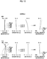
- FIG. 13 is a diagram of aberrations of the variable magnification optical system according to Example 3 of the present invention.
- FIG. 14 is a diagram of aberrations of the variable magnification optical system according to Example 4 of the present invention.
- FIG. 15 is a diagram of aberrations of the variable magnification optical system according to Example 5 of the present invention.
- FIG. 16 is a diagram of aberrations of the variable magnification optical system according to Example 6 of the present invention.
- FIG. 17 is a diagram of aberrations of the variable magnification optical system according to Example 7 of the present invention.
- FIG. 18 is a diagram of aberrations of the variable magnification optical system according to Example 8 of the present invention.
- FIG. 19 is a diagram of aberrations of the variable magnification optical system according to Example 9 of the present invention.
- FIG. 20 is a diagram of aberrations of the variable magnification optical system according to Example 10 of the present invention.
- FIG. 21 is a schematic configuration diagram of an imaging apparatus according to an embodiment of the present invention.
- FIG. 1 is a cross-sectional view illustrating a configuration and an optical path of a variable magnification optical system according to an embodiment of the present invention.
- FIG. 1 aberrations at the wide-angle end state are shown in the upper part indicated by “WIDE”, and aberrations at the telephoto end state are shown in the lower part indicated by “TELE”.
- the example shown in FIG. 1 corresponds to the variable magnification optical system of Example 1 to be described later.
- FIG. 1 shows a state where the object at infinity is in focus, where the left side of the drawing is the object side and the right side of the drawing is the image side.
- variable magnification optical system consists of, in order from the object side to the image side, a first optical system U 1 and a second optical system U 2 .
- the first optical system U 1 remains stationary with respect to an image plane Sim during changing magnification.
- the second optical system U 2 includes at least two positive lenses and at least one negative lens.
- the first optical system U 1 includes two reflecting mirrors having reflective surfaces arranged to face each other. According to this configuration, it is possible to shorten the total length by folding the optical path.
- the two reflecting mirrors consist of a first reflecting mirror and a second reflecting mirror.
- the first mirror M 1 of the present embodiment corresponds to the first reflecting mirror
- the second mirror M 2 corresponds to the second reflecting mirror.
- the first mirror M 1 is an optical element having a power at a position closest to the object side in the optical path.
- the dioptric system requires a large aperture, which is expensive.
- the center of gravity of the variable magnification optical system is biased toward the tip portion, and the weight balance thereof is deteriorated.
- this configuration is not preferable.
- the first mirror M 1 has a reflective surface concave toward the object side and is configured to reflect light, which is originated from the object, toward the object side.
- the second mirror M 2 has a reflective surface convex toward the image side and is configured to reflect the reflected light, which is reflected from the first mirror M 1 , toward the image side.
- the reflective surface of the first mirror M 1 and the reflective surface of the second mirror M 2 are preferably spherical. In such a case, the optical system can be manufactured inexpensively, and it is possible to reduce deterioration in image quality caused by eccentricity and/or collapse.
- the second optical system U 2 includes, in order from a position closest to the object side, a first lens group G 1 that consistently moves to the object side during changing magnification from a wide-angle end to a telephoto end and has a positive refractive power, and a second lens group G 2 that moves in a direction of an optical axis with a locus different from a locus of the first lens group G 1 during changing magnification and has a positive refractive power.
- the first lens group G 1 is disposed to be closest to the object side in the second optical system U 2
- the second lens group G 2 is disposed adjacent to the first lens group G 1 on the image side in the first lens group G 1 .
- the plurality of lens groups having positive refractive powers are continuously arranged in the second optical system U 2 which is a variable magnification optical system.
- the second optical system U 2 which is a variable magnification optical system.
- FIG. 1 shows a position P of the intermediate image in the optical axis.
- the intermediate image is re-formed on the image plane Sim through the second optical system U 2 . That is, the second optical system U 2 functions as a relay optical system.
- the variable magnification optical system as a reimaging optical system, it is possible to reduce the diameter of the lens group moving during changing magnification, and it is possible to achieve reduction in weight and an increase in speed of the changing magnification operation.
- the first optical system U 1 may be configured to include a field lens group Gfd which is a lens component closest to the intermediate image.
- a field lens group Gfd which is a lens component closest to the intermediate image.
- the “intermediate image” in the term “closest to the intermediate image” described herein is an intermediate image during focusing on the object at infinity.
- the “field lens group Gfd closest to the intermediate image” also includes a case where the position P of the intermediate image is located inside the field lens group Gfd. It is preferable that the field lens group Gfd is a lens group that consists of two or less lenses and has a positive refractive power.
- the field lens group Gfd in the example of FIG. 1 consists of a set of cemented lenses formed by cementing a lens Lf 1 having a negative power and a lens Lf 2 having a positive power in order from the object side.
- the lens Lf 1 is concave toward the object side
- the lens Lf 2 is convex toward the image side
- the cemented surface between the lens Lf 1 and the lens Lf 2 is convex toward the object side.
- the first optical system U 1 may be configured to include the correction lens group Gc having the effect of aberration correction.
- the correction lens group Gc preferably consists of two or less lenses having the common optical axis Z with respect to the first mirror M 1 and the second mirror M 2 .
- the correction lens group Gc consists of one lens.
- the correction lens group Gc in the example of FIG. 1 consists of only one lens Lc 1 .
- the lens Lc 1 in FIG. 1 is a meniscus lens convex toward the object side.
- the correction lens group Gc may consist of two lenses, and in such a case, astigmatism can be satisfactorily corrected.
- the correction lens group Gc may consist of two single lenses having a meniscus shape convex toward the object side.
- the correction lens group Gc be disposed both in the optical path from the first mirror M 1 to the second mirror M 2 and in the optical path from the second mirror M 2 to the position P of the intermediate image. That is, it is preferable to adopt a configuration in which the light passes the correction lens group Gc twice in a case where the light reflected by the first mirror M 1 is directed toward the second mirror M 2 and in a case where the light reflected by the second mirror M 2 is directed to the position P of the intermediate image.
- the correction lens group Gc is disposed in the optical path in which the light reciprocates. Thereby, even in a case where the number of optical elements such as lenses and mirrors is reduced, it becomes easy to satisfactorily correct spherical aberration. In addition, even in a case where the number of optical elements is reduced and both the first mirror M 1 and the second mirror M 2 do not use an aspheric surface, it becomes easy to satisfactorily correct spherical aberration.
- first mirror M 1 , the second mirror M 2 , the field lens group Gfd, and the correction lens group Gc are optical elements having powers included in the first optical system U 1 . Deterioration in the transmittance of the entire first optical system U 1 can be suppressed by reducing the number of optical elements.
- the first optical system U 1 has only a first mirror M 1 , a second mirror M 2 , a field lens group Gfd, and a correction lens group Gc as optical elements having powers.
- all the optical elements of the first optical system U 1 have a common optical axis Z.
- the second mirror M 2 is located closest to the object side
- the correction lens group Gc is disposed near the image side of the second mirror M 2
- the first mirror M 1 is disposed closer to the image side than the correction lens group Gc
- the field lens group Gfd is disposed near the first mirror M 1 .
- the first mirror M 1 has an annular shape of which the center is hollow. The intermediate image is located near the object side of the field lens group Gfd.
- the second optical system U 2 in the example of FIG. 1 consists of, in order from the object side to the image side along the optical axis Z, a first lens group G 1 , a second lens group G 2 , a third lens group G 3 , and a fourth lens group G 4 .
- the first lens group G 1 consists of three lenses L 11 to L 13
- the second lens group G 2 consists of one lens L 21
- the third lens group G 3 consists of four lenses L 31 to L 34
- the fourth lens group G 4 consists of one lens L 41 .
- the variable magnification optical system may be configured such that the number of lens groups composing the second optical system U 2 and the number of lenses composing each lens group are different from those in the example of FIG. 1 .
- the first lens group G 1 , the second lens group G 2 , and the third lens group G 3 move by changing the distances between adjacent lens groups in the direction of the optical axis, and the fourth lens group G 4 remains stationary with respect to the image plane Sim. That is, during changing magnification, the first lens group G 1 , the second lens group G 2 , and the third lens group G 3 move in the direction of the optical axis with loci different from one another.
- the first lens group G 1 , the second lens group G 2 , and the third lens group G 3 move in the direction of the optical axis with loci different from one another.
- the movement locus trG 1 of the first lens group G 1 , the movement locus trG 2 of the second lens group G 2 , the movement locus trG 3 of the third lens group G 3 , and the movement locus trG 4 of the fourth lens group G 4 are schematically indicated by arrows between the wide-angle end state and the telephoto end state.
- the movement locus of the lens group that does not move during changing magnification as in the fourth lens group G 4 is indicated by a straight arrow in the vertical direction.
- the lens closest to the object side in the first lens group has a negative refractive power and is concave toward the object side.
- the angle of the principal light of the off-axis light with respect to the optical axis Z can be reduced.
- the lens closest to the image side in the first lens group G 1 and the lens closest to the object side in the second lens group G 2 have positive refractive powers and are convex toward each other. In such a case, fluctuation in spherical aberration during changing magnification can be suppressed.
- the second optical system U 2 includes at least one lens group at the position closer to the image side than the second lens group G 2 , and the lens group closest to the image side in the second optical system U 2 has a positive refractive power.
- the lens group closest to the image side in the second optical system U 2 may be composed of one single lens. In such a case, it is possible to ensure the amounts of movement of the first lens group G 1 and the second lens group G 2 . As a result, there is an advantage in achieving a high variable magnification ratio while suppressing fluctuations in various aberrations.
- the second optical system U 2 consists of, in order from the object side, a first lens group G 1 having a positive refractive power, a second lens group G 2 having a positive refractive power, a third lens group G 3 having a negative refractive power, and a fourth lens group G 4 having a positive refractive power.
- the first lens group G 1 , the second lens group G 2 , the third lens group G 3 move in the direction of the optical axis with loci different from one another, and the fourth lens group G 4 remains stationary with respect to the image plane Sim. In such a case, fluctuation in astigmatism during changing magnification can be suppressed.
- the second optical system U 2 may consist of, in order from the object side, a first lens group G 1 having a positive refractive power, a second lens group G 2 having a positive refractive power, and a third lens group G 3 having a positive refractive power.
- the first lens group G 1 and the second lens group G 2 may move in the direction of the optical axis with loci different from one another, and the third lens group G 3 may remain stationary with respect to the image plane Sim.
- the second optical system U 2 may consist of, in order from the object side, a first lens group G 1 having a positive refractive power, a second lens group G 2 having a positive refractive power, and a third lens group G 3 having a positive refractive power.
- the first lens group G 1 , the second lens group G 2 , and the third lens group G 3 may move in the direction of the optical axis with loci different from one another.
- all the lens groups composing the second optical system U 2 have positive refractive powers, and the degree of freedom of the paraxial solution increases.
- the second optical system U 2 may consist of, in order from the object side, a first lens group G 1 having a positive refractive power and a second lens group G 2 having a positive refractive power.
- the first lens group G 1 and the second lens group G 2 may move in the direction of the optical axis with loci different from one another during changing magnification. In such a case, since the configuration is simple, the changing magnification mechanism can be simplified.
- focusing for example, it is possible to perform focusing by changing a distance between the first mirror M 1 and the second mirror M 2 .
- focusing may be performed by moving a part of the lens groups of the second optical system U 2 in the direction of the optical axis.
- variable magnification optical system of the present embodiment satisfies Conditional Expression (1).
- Conditional Expression (1) occurrence of secondary longitudinal chromatic aberration and secondary lateral chromatic aberration in the visible light region can be suppressed.
- Conditional Expression (2) Assuming that an average value of the Abbe numbers of all the positive lenses in the second optical system U 2 at the d line is ⁇ dp and an average value of the Abbe numbers of all the negative lenses in the second optical system U 2 at the d line is ⁇ dn, it is preferable to satisfy Conditional Expression (2). By not allowing the result of Conditional Expression (2) to be equal to or less than the lower limit, correction of longitudinal chromatic aberration becomes easy. By not allowing the result of Conditional Expression (2) to be equal to or greater than the upper limit, occurrence of secondary chromatic aberration can be suppressed. In addition, in a case of a configuration in which Conditional Expression (2-1) is satisfied, it is possible to obtain more favorable characteristics. 10 ⁇ dp ⁇ dn ⁇ 40 (2) 14 ⁇ dp ⁇ dn ⁇ 35 (2-1)
- Conditional Expression (3) occurrence of secondary chromatic aberration in the wavelength range from red to infrared can be suppressed.
- Conditional Expression (3-1) it is possible to obtain more favorable characteristics.
- Conditional Expression (3-2) it is possible to obtain further more favorable characteristics.
- Conditional Expression (4) Assuming that an average value of the partial dispersion ratios of all the negative lenses in the second optical system U 2 between the C line and the t line is ⁇ Ctn, it is preferable to satisfy Conditional Expression (4). By not allowing the result of Conditional Expression (4) to be equal to or less than the lower limit, it becomes easy to ensure a difference in Abbe number between the negative lens and the positive lens, and it becomes easy to correct the primary chromatic aberration. By not allowing the result of Conditional Expression (4) to be equal to or greater than the upper limit, it becomes easy to correct the secondary chromatic aberration in the wavelength range from red to infrared. In addition, in a case of a configuration in which Conditional Expression (4-1) is satisfied, it is possible to obtain more favorable characteristics. 0.75 ⁇ Ctn ⁇ 0.9 (4) 0.77 ⁇ Ctn ⁇ 0.85 (4-1)
- Conditional Expression (5) Assuming that an average value of the partial dispersion ratios of all the positive lenses in the second optical system U 2 between the C line and the t line is ⁇ Ctp, it is preferable to satisfy Conditional Expression (5). By not allowing the result of Conditional Expression (5) to be equal to or less than the lower limit, it becomes easy to correct the secondary chromatic aberration in the wavelength range from red to infrared. By not allowing the result of Conditional Expression (5) to be equal to or greater than the upper limit, it becomes easy to ensure a difference in Abbe number between the negative lens and the positive lens, and it becomes easy to correct the primary chromatic aberration. In addition, in a case of a configuration in which Conditional Expression (5-1) is satisfied, it is possible to obtain more favorable characteristics. 0.75 ⁇ Ctp ⁇ 0.9 (5) 0.78 ⁇ Ctp ⁇ 0.85 (5-1)
- Conditional Expression (6) Assuming that an average value of the Abbe numbers of all the negative lenses in the second optical system U 2 at the d line is ⁇ dn, it is preferable to satisfy Conditional Expression (6). By not allowing the result of Conditional Expression (6) to be equal to or less than the lower limit, it becomes easy to select a material having a small partial dispersion ratio between the g line and the F line, and it becomes easy to correct the secondary chromatic aberration in the visible light region. By not allowing the result of Conditional Expression (6) to be equal to or greater than the upper limit, it becomes easy to ensure a difference in Abbe number between the negative lens and the positive lens, and it becomes easy to correct the primary chromatic aberration. In addition, in a case of a configuration in which Conditional Expression (6-1) is satisfied, it is possible to obtain more favorable characteristics. 50 ⁇ dn ⁇ 65 (6) 52 ⁇ dn ⁇ 60 (6-1)
- Conditional Expression (7) Assuming that an average value of the refractive indices of all the negative lenses in the second optical system U 2 at the d line is Ndn, it is preferable to satisfy Conditional Expression (7).
- Conditional Expression (7) By not allowing the result of Conditional Expression (7) to be equal to or less than the lower limit, occurrence of higher order spherical aberration can be suppressed, and a material with a small Abbe number can be easily selected. As a result, there is an advantage in correction of primary chromatic aberration.
- the result of Conditional Expression (7) By not allowing the result of Conditional Expression (7) to be equal to or greater than the upper limit, the absolute value of the Petzval sum can be minimized, and the field curvature can be corrected well.
- Conditional Expression (8) Assuming that an average value of the partial dispersion ratios of all the negative lenses in the second optical system between the g line and the F line U 2 is ⁇ gFn, it is preferable to satisfy Conditional Expression (8). By not allowing the result of Conditional Expression (8) to be equal to or less than the lower limit, it becomes easy to ensure a difference in Abbe number between the negative lens and the positive lens, and it becomes easy to correct the primary chromatic aberration. By not allowing the result of Conditional Expression (8) to be equal to or greater than the upper limit, it becomes easy to correct the secondary chromatic aberration in the visible light region. In addition, in a case of a configuration in which Conditional Expression (8-1) is satisfied, it is possible to obtain more favorable characteristics. 0.53 ⁇ gFn ⁇ 0.58 (8) 0.535 ⁇ gFn ⁇ 0.565 (8-1)
- Conditional Expression (9) Assuming that an average value of the partial dispersion ratios of all the positive lenses in the second optical system U 2 between the g line and the F line is ⁇ gFp, it is preferable to satisfy Conditional Expression (9). By not allowing the result of Conditional Expression (9) to be equal to or less than the lower limit, it becomes easy to correct the secondary chromatic aberration in the visible light region. By not allowing the result of Conditional Expression (9) to be equal to or greater than the upper limit, it becomes easy to ensure a difference in Abbe number between the negative lens and the positive lens, and it becomes easy to correct the primary chromatic aberration. In addition, in a case of a configuration in which Conditional Expression (9-1) is satisfied, it is possible to obtain more favorable characteristics. 0.5 ⁇ gFp ⁇ 0.65 (9) 0.52 ⁇ gFp ⁇ 0.6 (9-1)
- Conditional Expression (10) Assuming that an average value of the Abbe numbers of all the positive lenses in the second optical system U 2 at the d line is ⁇ dp, it is preferable to satisfy Conditional Expression (10). By not allowing the result of Conditional Expression (10) to be equal to or less than the lower limit, it becomes easy to ensure a difference in Abbe number between the negative lens and the positive lens, and it becomes easy to correct the primary chromatic aberration. By not allowing the result of Conditional Expression (10) to be equal to or greater than the upper limit, it becomes easy to select a material having a large partial dispersion ratio between the g line and the F line, and it becomes easy to correct the secondary chromatic aberration in the visible light region. In addition, in a case of a configuration in which Conditional Expression (10-1) is satisfied, it is possible to obtain more favorable characteristics. 70 ⁇ dp ⁇ 100 (10) 72 ⁇ dp ⁇ 90 (10-1)
- Conditional Expression (11) an average value of the refractive indices of all the positive lenses in the second optical system U 2 at the d line is Ndp.
- the absolute value of the Petzval's sum can be suppressed small while suppressing occurrence of spherical aberration, and field curvature can be corrected well.
- the result of Conditional Expression (11) it becomes easy to select a material having a large Abbe number. As a result, there is an advantage in correction of primary chromatic aberration.
- Conditional Expression (11-1) it is possible to obtain more favorable characteristics. 1.43 ⁇ Ndp ⁇ 1.75 (11) 1.44 ⁇ Ndp ⁇ 1.55 (11-1)
- Conditional Expression (12) Assuming that a focal length of the second optical system U 2 at the telephoto end is fU 2 and a focal length of the first lens group G 1 is fG 1 , it is preferable to satisfy Conditional Expression (12). By not allowing the result of Conditional Expression (12) to be equal to or less than the lower limit, it is possible to achieve a high variable magnification ratio even in a case where the amount of movement of the first lens group G 1 during changing magnification is reduced. By not allowing the result of Conditional Expression (12) to be equal to or greater than the upper limit, fluctuation in spherical aberration during changing magnification can be suppressed. In addition, in a case of a configuration in which Conditional Expression (12-1) is satisfied, it is possible to obtain more favorable characteristics. 0.2 ⁇ fU 2/ fG 1 ⁇ 0.45 (12) 0.22 ⁇ fU 2/ fG 1 ⁇ 0.4 (12-1)
- Conditional Expression (13) Assuming that a radius of curvature of the reflective surface of the first mirror is rM 1 and a radius of curvature of the reflective surface of the second mirror is rM 2 , it is preferable to satisfy Conditional Expression (13). By not allowing the result of Conditional Expression (13) to be equal to or less than the lower limit, there is an advantage in shortening the total length. By not allowing the result of Conditional Expression (13) to be equal to or greater than the upper limit, it is possible to suppress occurrence of astigmatism. In addition, in a case of a configuration in which Conditional Expression (13-1) is satisfied, it is possible to obtain more favorable characteristics. In a case of a configuration in which Conditional Expression (13-2) is satisfied, it is possible to obtain further more favorable characteristics. 1 ⁇ rM 1/ rM 2 ⁇ 2.5 (13) 1.2 ⁇ rM 1/ rM 2 ⁇ 2.2 (13-1) 1.6 ⁇ rM 1/ rM 2 ⁇ 2.1 (13-2)
- Conditional Expression (14) Assuming that a radius of curvature of the reflective surface of the first mirror is rM 1 and a focal length of the correction lens group Gc is fC, it is preferable to satisfy Conditional Expression (14). By not allowing the result of Conditional Expression (14) to be equal to or less than the lower limit, there is an advantage in correction of spherical aberration. By not allowing the result of Conditional Expression (14) to be equal to or greater than the upper limit, longitudinal chromatic aberration can be suppressed and occurrence of difference in spherical aberration due to wavelength can be suppressed. In addition, in a case of a configuration in which Conditional Expression (14-1) is satisfied, it is possible to obtain more favorable characteristics.
- Conditional Expression (15) a lateral magnification of the second optical system U 2 at the telephoto end during focusing on an object at infinity is ⁇ rT and a variable magnification ratio of the variable magnification optical system is MAG.
- Conditional Expression (15) By not allowing the result of Conditional Expression (15) to be equal to or less than the lower limit, fluctuation in spherical aberration during changing magnification can be suppressed.
- Conditional Expression (15) By not allowing the result of Conditional Expression (15) to be equal to or greater than the upper limit, it is possible to achieve a high variable magnification ratio even in a case where the amount of movement of the lens group moving during changing magnification is reduced.
- Conditional Expression (15-1) it is possible to obtain more favorable characteristics.
- Conditional Expression (16) it is preferable to satisfy Conditional Expression (16).
- Conditional Expression (16) it is possible to make the off-axis light intersect the optical axis Z at an appropriate position. As a result, there is an advantage in reducing the diameter of the lens group moving during changing magnification.
- Conditional Expression (16-1) it is possible to obtain more favorable characteristics.
- Conditional Expression (17) it is possible to appropriately distribute the refractive power to the first lens group G 1 and the second lens group G 2 . Thereby, it is possible to suppress fluctuation in spherical aberration during changing magnification, and it is also possible to reduce the effective diameters of the first lens group G 1 and the second lens group G 2 .
- Conditional Expression (17-1) it is possible to obtain more favorable characteristics.
- various types of parallel plate shaped filters and/or cover glasses may be disposed between the lens closest to the image side and the image plane Sim and/or between an optical element and an optical element. It is possible to modify change in aberration, which is caused by arranging the various filters and/or the cover glass, to such a degree that does not cause a practical problem, by changing a small number of design parameters.
- variable magnification optical system which has small fluctuations in various aberrations during changing magnification and has favorable optical performance while achieving a high variable magnification ratio.
- high variable magnification ratio means that the variable magnification ratio is equal to or greater than 4 times.
- variable magnification optical system of the present invention will be described.
- variable magnification optical system of Example 1 consists of, in order from the object side to the image side, a first optical system U 1 and a second optical system U 2 .
- the first optical system U 1 remains stationary with respect to an image plane Sim during changing magnification.
- the second optical system U 2 includes a plurality of lens groups that move during changing magnification.
- the first optical system U 1 consists of a ring-shaped first mirror M 1 , a second mirror M 2 , a correction lens group Gc, and a field lens group Gfd.
- the correction lens group Gc consists of one lens Lc 1 .
- the field lens group Gfd consists of two lenses Lf 1 and Lf 2 in order from the object side.
- the optical elements of the first optical system U 1 all have a common optical axis Z.
- An intermediate image is formed in the vicinity of the object side of the field lens group Gfd in a state where the object at infinity is in focus.
- the first mirror M 1 is an optical element having a power at the position closest to the object side in the optical path and also functions as a stop surface. Light from the object passes through the first mirror M 1 , the correction lens group Gc, the second mirror M 2 , the correction lens group Gc, and the field lens group Gfd in this order, and is then incident into the second optical system U 2 .
- the second optical system U 2 consists of, in order from the object side, a first lens group G 1 having a positive refractive power, a second lens group G 2 having a positive refractive power, a third lens group G 3 having a negative refractive power, and a fourth lens group G 4 having a positive refractive power.
- the first lens group G 1 consists of three lenses L 11 to L 13 .
- the second lens group G 2 consists of one lens L 21 .
- the third lens group G 3 consists of four lenses L 31 to L 34 .
- the fourth lens group G 4 consists of one lens L 41 .
- the third lens group G 3 has a cemented lens in which a positive lens and a negative lens are cemented. The outline of the variable magnification optical system of Example 1 has been described above.
- Table 1 shows basic lens data of the variable magnification optical system of Example 1
- Table 2 shows specification and variable surface distances
- Table 3 shows aspheric surface coefficients thereof.
- Tables 1 and 2 show data in a state where the object at infinity is in focus.
- Table 1 shows constituent elements along the optical path.
- the column of the surface number shows surface numbers. The surface closest to the object side on the optical path is the first surface, and the surface numbers increase one by one toward the image side along the optical path.
- the column of r shows radii of curvature of the respective surfaces.
- the column of d shows surface distances on the optical axis between the respective surfaces and the surfaces adjacent to the image side on the optical path.
- the column of material shows the material names of the respective constituent elements and the names of the manufacturers of the materials with under bars interposed therebetween.
- the manufacturer names are shown schematically.
- “OHARA” is OHARA CORPORATION.
- the column of Nd in Table 1 shows the refractive indices of the respective constituent elements at the d line.
- the column of ⁇ d shows the Abbe numbers of the respective constituent elements at the d line.
- the column of ⁇ gF shows the partial dispersion ratios of the respective constituent elements between the g line and the F line.
- the column of ⁇ Ct shows the partial dispersion ratios of the respective constituent elements between the C line and the t line.
- Table 2 the absolute value of the focal length of the whole system, the F number, the maximum image height, and the maximum half angle of view are shown in the rows labeled “
- Table 2 shows the values of the variable surface distances. The values shown in Table 2 are values on the d line basis.
- Table 2 the respective values of the wide-angle end state, the first intermediate focal length state, the second intermediate focal length state, and the telephoto end state are shown in the columns labeled W, M 1 , M 2 , and T, respectively.
- Table 1 the reference sign * is attached to surface numbers of aspheric surfaces, and numerical values of the paraxial radius of curvature are written into the column of the radius of curvature of the aspheric surface.
- the “E ⁇ n” (n: an integer) in numerical values of the aspheric surface coefficients of Table 3 indicates “ ⁇ 10 ⁇ n ”.
- Zd is an aspheric surface depth (a length of a perpendicular from a point on an aspheric surface at height h to a plane that is perpendicular to the optical axis and contacts with the vertex of the aspheric surface),
- h is a height (a distance from the optical axis to the lens surface)
- K and Am are aspheric surface coefficients
- ⁇ in the aspheric surface expression means the sum with respect to m.
- each table shows numerical values rounded off to predetermined decimal places.
- FIG. 11 shows aberration diagrams in a state where an object at the infinity is brought into focus through the variable magnification optical system of Example 1.
- FIG. 11 in order from the left side, spherical aberration, astigmatism, distortion, and lateral chromatic aberration are shown.
- FIG. 11 aberrations at the wide-angle end state are shown in the upper part indicated by WIDE, and aberrations at the telephoto end state are shown in the lower part indicated by TELE.
- the aberrations at a wavelength of 1970.1 nm, the C line, the d line, the F line, and the g line are indicated by the long dashed line, the chain line, the solid line, the short dashed line, and the chain double-dashed line, respectively.
- aberration in the sagittal direction at the d line is indicated by the solid line
- aberration in the tangential direction at the d line is indicated by the short dashed line.
- aberration at the d line is indicated by the solid line.
- the aberration at the wavelength of 1970.1 nm and the g line is indicated by the long dashed line and the chain double-dashed line, respectively.
- FNo. indicates the F number.
- IH indicates the image height. Since the first mirror M 1 has a ring shape, the data in the vicinity of 0 on the vertical axis of the spherical aberration diagram of FIG. 11 is shown as reference data.
- FIG. 2 shows a cross-sectional view and an optical path of the variable magnification optical system of Example 2.
- the variable magnification optical system of Example 2 has the same configuration as the outline of the variable magnification optical system of Example 1.
- Table 4 shows basic lens data of the variable magnification optical system of Example 2
- Table 5 shows specification and variable surface distances
- FIG. 12 shows aberration diagrams thereof.
- FIG. 3 shows a cross-sectional view and an optical path of the variable magnification optical system of Example 3.
- the variable magnification optical system of Example 3 is different from the variable magnification optical system of Example 1 in that the correction lens group Gc consists of two lenses Lc 1 and Lc 2 and the third lens group G 3 consists of three lenses L 31 to L 33 .
- the other configuration is the same as the outline of the variable magnification optical system of Example 1.
- Table 6 shows basic lens data of the variable magnification optical system of Example 3
- Table 7 shows specification and variable surface distances
- FIG. 13 shows aberration diagrams thereof.
- FIG. 4 shows a cross-sectional view and an optical path of the variable magnification optical system of Example 4.
- the variable magnification optical system of Example 4 is different from that of Example 1 in that the correction lens group Gc consists of two lenses Lc 1 and Lc 2 .
- the other configuration is the same as the outline of the variable magnification optical system of Example 1.
- Table 8 shows basic lens data of the variable magnification optical system of Example 4
- Table 9 shows specification and variable surface distances
- FIG. 14 shows aberration diagrams thereof.
- FIG. 5 shows a cross-sectional view and an optical path of the variable magnification optical system of Example 5.
- the variable magnification optical system of Example 5 is different from that of Example 1 in that the correction lens group Gc consists of two lenses Lc 1 and Lc 2 .
- the other configuration is the same as the outline of the variable magnification optical system of Example 1.
- Table 10 shows basic lens data of the variable magnification optical system of Example 5
- Table 11 shows specification and variable surface distances
- FIG. 15 shows aberration diagrams thereof.
- FIG. 6 shows a cross-sectional view and an optical path of the variable magnification optical system of Example 6.
- the variable magnification optical system of Example 6 is different from that of Example 1 in that the correction lens group Gc consists of two lenses Lc 1 and Lc 2 .
- the other configuration is the same as the outline of the variable magnification optical system of Example 1.
- Table 12 shows basic lens data of the variable magnification optical system of Example 6
- Table 13 shows specification and variable surface distances
- FIG. 16 shows aberration diagrams thereof.
- FIG. 7 shows a cross-sectional view and an optical path of the variable magnification optical system of Example 7.
- the variable magnification optical system of Example 7 is different from Example 1 in that the correction lens group Gc consists of two lenses Lc 1 and Lc 2 and the configuration of the second optical system U 2 is different.
- the configuration of the first optical system U 1 is the same as that of the outline of the variable magnification optical system of Example 1 except the correction lens group Gc.
- the second optical system U 2 of Example 7 consists of, in order from the object side, a first lens group G 1 having a positive refractive power, a second lens group G 2 having a positive refractive power, and a third lens group G 3 having a positive refractive power.
- the first lens group G 1 and the second lens group G 2 move in the direction of the optical axis with loci different from each other, and the third lens group G 3 remains stationary with respect to the image plane Sim.
- the first lens group G 1 consists of three lenses L 11 to L 13 .
- the second lens group G 2 consists of five lenses L 21 to L 25 .
- the third lens group G 3 consists of one lens L 31 .
- the second lens group G 2 has a cemented lens in which a positive lens and a negative lens are cemented. The outline of the variable magnification optical system of Example 7 has been described above.
- Table 14 shows basic lens data of the variable magnification optical system of Example 7
- Table 15 shows specification and variable surface distances
- FIG. 17 shows aberration diagrams thereof.
- FIG. 8 shows a cross-sectional view and an optical path of the variable magnification optical system of Example 8.
- the variable magnification optical system of Example 8 has the same configuration as the outline of the variable magnification optical system of Example 7.
- Table 16 shows basic lens data of the variable magnification optical system of Example 8
- Table 17 shows specification and variable surface distances
- FIG. 18 shows aberration diagrams thereof.
- FIG. 9 shows a cross-sectional view and an optical path of the variable magnification optical system of Example 9.
- the variable magnification optical system of Example 9 is different from that of Example 7 in that the first lens group G 1 , the second lens group G 2 , and the third lens group G 3 move in the direction of the optical axis with loci different from one another during changing magnification.
- the other configuration is the same as the outline of the variable magnification optical system of Example 7.
- Table 18 shows basic lens data of the variable magnification optical system of Example 9
- Table 19 shows specification and variable surface distances
- FIG. 19 shows aberration diagrams thereof.
- FIG. 9 shows a cross-sectional view and an optical path of the variable magnification optical system of Example 10.
- the variable magnification optical system of Example 10 is different from that of Example 7 in the configuration of the second optical system U 2 .
- the configuration of the first optical system U 1 is the same as the outline of the variable magnification optical system of Example 7.
- the second optical system U 2 of Example 10 consists of, in order from the object side, a first lens group G 1 having a positive refractive power and a second lens group G 2 having a positive refractive power.
- the first lens group G 1 and the second lens group G 2 move in the direction of the optical axis with loci different from one another during changing magnification.
- the first lens group G 1 consists of three lenses L 11 to L 13 .
- the second lens group G 2 consists of seven lenses L 21 to L 27 .
- the second lens group G 2 has two sets of cemented lenses in which a positive lens and a negative lens are cemented.
- Table 20 shows basic lens data of the variable magnification optical system of Example 10, Table 21 shows specification and variable surface distances, Table 22 shows aspheric surface coefficients, and FIG. 20 shows aberration diagrams.
- Table 23 shows values corresponding to Conditional Expressions (1) to (17) of the variable magnification optical systems of Examples 1 to 10. Corresponding values other than the partial dispersion ratios in Table 23 are values on the d line basis.
- Example 1 Example 2
- Example 3 Example 4
- Example 5 (1) ⁇ gFp ⁇ ⁇ gFn ⁇ 0.0022 ⁇ 0.0051 0.0073 ⁇ 0.0097 ⁇ 0.0017 (2) ⁇ dp ⁇ ⁇ dn 27.47 29.07 16.92 31.84 25.24 (3) ⁇ Ctp ⁇ ⁇ Ctn ⁇ 0.0137 ⁇ 0.0046 ⁇ 0.0356 0.0083 ⁇ 0.0156 (4) ⁇ Ctn 0.8375 0.8375 0.8375 0.8098 0.8375 (5) ⁇ Ctp 0.8238 0.8329 0.8019 0.8181 0.8219 (6) ⁇ dn 58.76 58.76 58.76 54.44 58.76 (7) Ndn 1.60472 1.60472 1.60472 1.60042 1.60472 (8) ⁇ gFn 0.5414 0.5414 0.5414 0.5496 0.5414 (9) ⁇ gFp 0.5391 0.5363 0.5487 0.5399 0.5397 (10) ⁇ dp 86.23 87.
- variable magnification optical systems of Examples 1 to 10 fluctuation in various aberrations during changing magnification is small, the variable magnification ratio is equal to or greater than 4.9 times, a high variable magnification ratio is achieved, and the load of the object side portion can be reduced.
- the variable magnification optical system can be configured with low costs, various aberrations are satisfactorily corrected in a wide range from the visible light region to the infrared light region, and high optical performance is achieved.
- FIG. 21 is a schematic configuration diagram of an imaging apparatus 10 using the variable magnification optical system 1 according to the above-mentioned embodiment of the present invention as an example of an imaging apparatus of an embodiment of the present invention.
- the imaging apparatus 10 for example, there is a surveillance camera, a video camera, an electronic still camera, or the like.
- the imaging apparatus 10 comprises: the variable magnification optical system 1 ; a filter 4 that is disposed on the image side of the variable magnification optical system 1 ; an imaging element 5 that captures an image of a subject formed by the variable magnification optical system 1 ; a signal processing section 6 that arithmetically processes an output signal which is output from the imaging element 5 ; and a changing magnification controller 7 that changes the variable magnification ratio of the variable magnification optical system 1 .
- FIG. 21 schematically shows the first optical system U 1 and the second optical system U 2 included in the variable magnification optical system 1 .
- the imaging element 5 captures an image of a subject formed by the variable magnification optical system 1 and converts the image into an electric signal.
- the imaging element 5 is disposed such that the imaging surface thereof is coplanar with the image plane of the variable magnification optical system 1 .
- the imaging element 5 for example, it is possible to use a charge coupled device (CCD), a complementary metal oxide semiconductor (CMOS), or the like.
- CCD charge coupled device
- CMOS complementary metal oxide semiconductor
- FIG. 21 shows only one imaging element 5 , but the imaging apparatus of the present invention is not limited to this, and may be a so-called three-plate imaging apparatus having three imaging elements.
- the present invention has been hitherto described through embodiments and examples, but the present invention is not limited to the above-mentioned embodiments and examples, and may be modified into various forms.
- values such as the radius of curvature, the surface distance, the refractive index, the Abbe number, and the aspheric surface coefficient of each optical element are not limited to the values shown in the numerical examples, and different values may be used therefor.
Landscapes
- Physics & Mathematics (AREA)
- General Physics & Mathematics (AREA)
- Optics & Photonics (AREA)
- Nonlinear Science (AREA)
- Chemical & Material Sciences (AREA)
- Dispersion Chemistry (AREA)
- Lenses (AREA)
Abstract
Description
−0.04<θgFp−θgFn<0.1 (1)
−0.02<θgFp−θgFn<0.06 (1-1)
10<νdp−νdn<40 (2)
14<νdp−νdn<35 (2-1)
−0.1<θCtp−θCtn<0.1 (3)
−0.07<θCtp−θCtn<0.05 (3-1)
0.75<θCtn<0.9 (4)
0.77<θCtn<0.85 (4-1)
0.75<θCtp<0.9 (5)
0.78<θCtp<0.85 (5-1)
50<νdn<65 (6)
1.5<Ndn<1.75 (7)
0.53<θgFn<0.58 (8)
0.5<θgFp<0.65 (9)
70<νdp<100 (10)
1.43<Ndp<1.75 (11)
−0.04<θgFp−θgFn<0.1 (1)
−0.02<θgFp−θgFn<0.06 (1-1)
−0.015<θgFp−θgFn<0 (1-2)
10<νdp−νdn<40 (2)
14<νdp−νdn<35 (2-1)
−0.1<θCtp−θCtn<0.1 (3)
−0.07<θCtp−θCtn<0.05 (3-1)
−0.06<θCtp−θCtn<0.015 (3-2)
0.75<θCtn<0.9 (4)
0.77<θCtn<0.85 (4-1)
0.75<θCtp<0.9 (5)
0.78<θCtp<0.85 (5-1)
50<νdn<65 (6)
52<νdn<60 (6-1)
1.5<Ndn<1.75 (7)
1.55<Ndn<1.7 (7-1)
1.57<Ndn<1.65 (7-2)
0.53<θgFn<0.58 (8)
0.535<θgFn<0.565 (8-1)
0.5<θgFp<0.65 (9)
0.52<θgFp<0.6 (9-1)
70<νdp<100 (10)
72<νdp<90 (10-1)
1.43<Ndp<1.75 (11)
1.44<Ndp<1.55 (11-1)
0.2<fU2/fG1<0.45 (12)
0.22<fU2/fG1<0.4 (12-1)
1<rM1/rM2<2.5 (13)
1.2<rM1/rM2<2.2 (13-1)
1.6<rM1/rM2<2.1 (13-2)
0.07<rM1/fC<0.5 (14)
0.1<rM1/fC<0.45 (14-1)
0.2<rM1/fC<0.4 (14-2)
−0.45<βrT/MAG<−0.25 (15)
−0.4<βrT/MAG<−0.28 (15-1)
0.4<fFd/LA<1 (16)
0.5<fFd/LA<0.8 (16-1)
0.55<fFd/LA<0.75 (16-2)
1.5<fG1/fG2<4 (17)
1.7<fG1/fG2<3.8 (17-1)
Zd=C×h 2/{1+(1−(1+K)×C 2 ×h 2)1/2 }+ΣAm××h m
| TABLE 1 |
| Example 1 |
| Surface number | r | d | Material | Nd | νd | θgF | θCt |
| 1 (Reflective | −1033.81950 | −316.344 | |||||
| surface) | |||||||
| 2* | 135.65558 | −35.000 | LBSLOHARA | 1.516330 | 64.06 | 0.5333 | 0.8785 |
| 3* | 143.67806 | −0.200 | |||||
| 4 (Reflective | −831.53073 | 0.200 | |||||
| surface) | |||||||
| 5* | 143.67806 | 35.000 | LBSL7_OHARA | 1.516330 | 64.06 | 0.5333 | 0.8785 |
| 6* | 135.65558 | 0.000 | |||||
| 7 (Intermediate | ∞ | 3.560 | |||||
| image) | |||||||
| 8 | −51.26904 | 14.405 | SNBH56_OHARA | 1.854780 | 24.80 | 0.6122 | 0.6739 |
| 9 | 71.05768 | 15.000 | SLAH88_OHARA | 1.916500 | 31.60 | 0.5911 | 0.7059 |
| 10 | −48.49433 | D10 | |||||
| 11 | −22.56452 | 3.200 | SLAL59_OHARA | 1.733997 | 51.47 | 0.5486 | 0.8067 |
| 12 | 66.03152 | 1.749 | |||||
| 13 | 9397.11500 | 9.462 | SFPL53_OHARA | 1.438750 | 94.93 | 0.5340 | 0.8373 |
| 14 | −31.43051 | 0.200 | |||||
| 15 | 121.79684 | 13.350 | SFPL53_OHARA | 1.438750 | 94.93 | 0.5340 | 0.8373 |
| 16 | −30.30142 | D16 | |||||
| 17 | 35.62791 | 11.146 | SFPL53_OHARA | 1.438750 | 94.93 | 0.5340 | 0.8373 |
| 18 | −160.92832 | D18 | |||||
| 19 | 35.24937 | 3.300 | SFPL53_OHARA | 1.438750 | 94.93 | 0.5340 | 0.S373 |
| 20 | 50.73617 | 0.200 | |||||
| 21 | 23.48294 | 7.272 | SFPL53_OHARA | 1.438750 | 94.93 | 0.5340 | 0.8373 |
| 22 | −63.70289 | 2.178 | SBAL41_OHARA | 1.563839 | 60.67 | 0.5402 | 0.8370 |
| 23 | 16.23503 | 5.280 | |||||
| 24 | −37.39752 | 3.822 | SBSL7_OHARA | 1.516330 | 64.14 | 0.5353 | 0.8687 |
| 25 | −90.13226 | D25 | |||||
| 26 | 2456.86976 | 2.800 | SLAH55V_OHARA | 1.834807 | 42.73 | 0.5648 | 0.7563 |
| 27 | −171.39974 | 40.251 | |||||
| 28 (Image plane) | ∞ | ||||||
| TABLE 2 |
| Example 1 |
| W | M1 | M2 | T | ||
| |Focal length| | 500.007 | 1036.655 | 1399.998 | 2501.077 |
| FNo. | 3.125 | 6.479 | 8.750 | 15.632 |
| Image height | 8.000 | 8.000 | 8.000 | 8.000 |
| Half angle of view | 0.917 | 0.463 | 0.327 | 0.183 |
| D10 | 135.264 | 70.000 | 49.821 | 32.910 |
| D16 | 3.142 | 44.324 | 43.953 | 11.343 |
| D18 | 2.075 | 2.300 | 2.431 | 2.641 |
| D25 | 10.601 | 34.458 | 54.877 | 104.188 |
| TABLE 3 |
| Example 1 |
| Second surface Sixth surface |
| K | 2.4308490E+00 | |
| A4 | −2.3068712E−07 | |
| A6 | 1.3696765E−12 | |
| A8 | −7.7228548E−15 | |
| A10 | 0.0000000E+00 |
| Third surface Fifth surface |
| K | −1.5862915E+00 | |
| A4 | −2.7678049E−08 | |
| A6 | 1.7465463E−11 | |
| A8 | −5.7911503E−15 | |
| A10 | 0.0000000E+00 | |
| TABLE 4 |
| Example 2 |
| Surface number | r | d | Material | Nd | νd | θgF | θCt |
| 1 (Reflective | −940.33887 | −295.360 | |||||
| surface) | |||||||
| 2 | 163.45951 | −35.000 | SFSL5_OHARA | 1.487490 | 70.23 | 0.5300 | 0.8924 |
| 3 | 158.26945 | −11.507 | |||||
| 4 (Reflective | −492.11463 | 11.507 | |||||
| surface) | |||||||
| 5 | 158.26945 | 35.000 | SFSL5_OHARA | 1.487490 | 70.23 | 0.5300 | 0.8924 |
| 6 | 163.45951 | 295.560 | |||||
| 7 (Intermediate | ∞ | 2.640 | |||||
| image) | |||||||
| 8 | −98.83269 | 14.797 | SNBH56_OHARA | 1.854780 | 24.80 | 0.6122 | 0.6739 |
| 9 | 186.03574 | 14.407 | SLAH88_OHARA | 1.916500 | 31.60 | 0.5911 | 0.7059 |
| 10 | −63.52799 | D10 | |||||
| 11 | −20.22194 | 3.200 | SLAL59_OHARA | 1.733997 | 51.47 | 0.5486 | 0.8067 |
| 12 | 70.08051 | 1.808 | |||||
| 13 | −677.79831 | 8.251 | SFPL53_OHARA | 1.438750 | 94.93 | 0.5340 | 0.8373 |
| 14 | −28.43741 | 0.200 | |||||
| 15 | 129.06346 | 11.928 | SFPL53_OHARA | 1.438750 | 94.93 | 0.5340 | 0.8373 |
| 16 | −27.89917 | D16 | |||||
| 17 | 35.78594 | 13.782 | SFPL53_OHARA | 1.438750 | 94.93 | 0.5340 | 0.8373 |
| 18 | 235.02306 | D18 | |||||
| 19 | 40.31663 | 3.300 | SFPL53_OHARA | 1.438750 | 94.93 | 0.5340 | 0.8373 |
| 20 | 182.77982 | 0.200 | |||||
| 21 | 21.85254 | 7.807 | SFPL53_OHARA | 1.438750 | 94.93 | 0.5340 | 0.8373 |
| 22 | −54.44619 | 2.021 | SBAL41_OHARA | 1.563839 | 60.67 | 0.5402 | 0.8370 |
| 23 | 15.24145 | 6.357 | |||||
| 24 | −35.58368 | 2.000 | SBSL7_OHARA | 1.516330 | 64.14 | 0.5353 | 0.8687 |
| 25 | −112.05865 | D25 | |||||
| 26 | 922.59801 | 4.036 | SYGH51_OHARA | 1.754999 | 52.32 | 0.5475 | 0.8107 |
| 27 | −166.51349 | 40.150 | |||||
| 28 (Image plane) | ∞ | ||||||
| TABLE 5 |
| Example 2 |
| W | M1 | M2 | T | ||
| |Focal length| | 500.039 | 1224.572 | 1399.989 | 2497.541 |
| FNo. | 3.125 | 7.654 | 8.750 | 15.610 |
| Image height | 8.000 | 8.000 | 8.000 | 8.000 |
| Half angle of | 0.917 | 0.374 | 0.327 | 0.184 |
| view | ||||
| D10 | 146.085 | 70.000 | 63.362 | 46.788 |
| D16 | 3.746 | 42.125 | 39.876 | 5.033 |
| D18 | 9.207 | 9.161 | 9.244 | 9.418 |
| D25 | 2.009 | 39.762 | 48.566 | 99.809 |
| TABLE 6 |
| Example 3 |
| Surface number | r | d | Material | Nd | νd | θgF | θCt |
| 1 (Reflective | −922.75595 | −294.382 | |||||
| surface) | |||||||
| 2 | 189.54097 | −10.000 | SFSLS_OHARA | 1.487490 | 70.23 | 0.5300 | 0.8924 |
| 3 | 1188.04152 | −17.474 | |||||
| 4 | 775.56532 | −10.000 | SFSL5_OHARA | 1.487490 | 70.23 | 0.5300 | 0.8924 |
| 5 | 168.65411 | −0.200 | |||||
| 6 (Reflective | −483.32143 | 0.200 | |||||
| surface) | |||||||
| 7 | 168.65411 | 10.000 | SFSL5_OHARA | 1.487490 | 70.23 | 0.5300 | 0.8924 |
| 8 | 775.56532 | 17.474 | |||||
| 9 | 1188.04152 | 10.000 | SFSL5_OHARA | 1.487490 | 70.23 | 0.5300 | 0.8924 |
| 10 | 189.54097 | 294.619 | |||||
| 11 (Intermediate | ∞ | 3.810 | |||||
| image) | |||||||
| 12 | −57.05882 | 14.856 | SNBH56_OHARA | 1.854780 | 24.80 | 0.6122 | 0.6739 |
| 13 | 848.85181 | 14.868 | SLAH88_OHARA | 1.916500 | 31.60 | 0.5911 | 0.7059 |
| 14 | −50.50565 | D14 | |||||
| 15 | −21.92011 | 3.200 | SLAL59_OHARA | 1.733997 | 51.47 | 0.5486 | 0.8067 |
| 16 | 70.08315 | 1.8457 | |||||
| 17 | −1000.87953 | 9.379 | SFPL53_OHARA | 1.438750 | 94.93 | 0.5340 | 0.8373 |
| 18 | −29.90597 | 0.2000 | |||||
| 19 | 117.46531 | 12.938 | SFPL53_OHARA | 1.438750 | 94.93 | 0.5340 | 0.8373 |
| 20 | −30.24255 | D20 | |||||
| 21 | 41.54994 | 14.161 | SFPL53_OHARA | 1.438750 | 94.93 | 0.5340 | 0.8373 |
| 22 | −211.60538 | D22 | |||||
| 23 | 27.74930 | 9.988 | SFPL53_OHARA | 1.438750 | 94.93 | 0.5340 | 0.8373 |
| 24 | −55.08377 | 2.046 | SBAL41_OHARA | 1.563839 | 60.67 | 0.5402 | 0.8370 |
| 25 | 21.88803 | 6.468 | |||||
| 26 | −26.95242 | 2.000 | SBSL7_OHARA | 1.516330 | 64.14 | 0.5353 | 0.8687 |
| 27 | −30.14825 | D27 | |||||
| 28 | 93.06881 | 2.000 | SLAH55V_OHARA | 1.834807 | 42.73 | 0.5648 | 0.7563 |
| 29 | 176.36037 | 52.182 | |||||
| 30 (Image plane) | ∞ | ||||||
| TABLE 7 |
| Example 3 |
| W | M1 | M2 | T | ||
| |Focal length| | 500.485 | 1117.112 | 1400.022 | 2475.451 |
| FNo. | 3.128 | 6.982 | 8.750 | 15.472 |
| Image height | 8.000 | 8.000 | 8.000 | 8.000 |
| Half angle of | 0.916 | 0.410 | 0.327 | 0.185 |
| view | ||||
| D14 | 149.026 | 70.000 | 55.561 | 34.238 |
| D20 | 3.545 | 49.642 | 49.123 | 18.792 |
| D22 | 3.230 | 2.259 | 2.420 | 2.765 |
| D27 | 2.000 | 35.900 | 50.696 | 102.006 |
| TABLE 8 |
| Example 4 |
| Surface number | r | d | Material | Nd | νd | θgF | θCt |
| 1 (Reflective | −953.77868 | −286.986 | |||||
| surface) | |||||||
| 2 | 232.21307 | −10.000 | SBSL7_OHARA | 1.516330 | 64.14 | 0.5353 | 0.8687 |
| 3 | 390.17511 | −32.789 | |||||
| 4 | 300.32692 | −10.000 | SBSL7_OHARA | 1.516330 | 64.14 | 0.5353 | 0.8687 |
| 5 | 184.88521 | −0.200 | |||||
| 6 (Reflective | −508.96238 | 0.200 | |||||
| surface) | |||||||
| 7 | 184.88521 | 10.000 | SBSL7_OHARA | 1.516330 | 64.14 | 0.5353 | 0.8687 |
| 8 | 300.32692 | 32.789 | |||||
| 9 | 390.17511 | 10.000 | SBSL7_OHARA | 1.516330 | 64.14 | 0.5353 | 0.8687 |
| 10 | 232.21307 | 287.186 | |||||
| 11 (Intermediate | ∞ | 3.939 | |||||
| image) | |||||||
| 12 | −53.49439 | 14.432 | SNBH56_OHARA | 1.854780 | 24.80 | 0.6122 | 0.6739 |
| 13 | 92.68066 | 15.000 | SLAH88_OHARA | 1.916500 | 31.60 | 0.5911 | 0.7059 |
| 14 | −50.17468 | D14 | |||||
| 15 | −23.57864 | 3.200 | SLAL10_OHARA | 1.719995 | 50.23 | 0.5521 | 0.7931 |
| 16 | 70.45288 | 2.0203 | |||||
| 17 | 641.58789 | 9.923 | SFPL53_OHARA | 1.438750 | 94.93 | 0.5340 | 0.8373 |
| 18 | −33.26453 | 0.8596 | |||||
| 19 | 143.69669 | 15.000 | CAF2_SCHOTT | 1.433848 | 95.23 | 0.5386 | 0.8031 |
| 20 | −32.97214 | D20 | |||||
| 21 | 35.50896 | 15.000 | SFPL53_OHARA | 1.438750 | 94.93 | 0.5340 | 0.8373 |
| 22 | −178.58929 | D22 | |||||
| 23 | 33.09074 | 3.300 | SFPL53_OHARA | 1.438750 | 94.93 | 0.5340 | 0.8373 |
| 24 | 51.55537 | 0.200 | |||||
| 25 | 21.89785 | 7.017 | SFPL53_OHARA | 1.438750 | 94.93 | 0.5340 | 0.8373 |
| 26 | −61.72367 | 2.040 | SBAL41_OHARA | 1.563839 | 60.67 | 0.5402 | 0.8370 |
| 27 | 15.20944 | 5.086 | |||||
| 28 | −33.60080 | 9.237 | SNSL36_OHARA | 1.517417 | 52.43 | 0.5564 | 0.7992 |
| 29 | −87.39336 | D29 | |||||
| 30 | 1302.49303 | 2.000 | SLAH55V_OHARA | 1.834807 | 42.73 | 0.5648 | 0.7563 |
| 31 | −172.47891 | 40.000 | |||||
| 32 (Image plane) | ∞ | ||||||
| TABLE 9 |
| Example 4 |
| W | M1 | M2 | T | ||
| |Focal length| | 500.485 | 1117.112 | 1400.022 | 2475.451 |
| FNo. | 3.128 | 6.982 | 8.750 | 15.472 |
| Image height | 8.000 | 8.000 | 8.000 | 8.000 |
| Half angle of view | 0.916 | 0.410 | 0.327 | 0.185 |
| D14 | 143.316 | 70.000 | 51.042 | 32.247 |
| D20 | 3.000 | 51.755 | 53.198 | 24.447 |
| D22 | 3.255 | 3.455 | 3.536 | 3.686 |
| D29 | 2.000 | 26.362 | 43.795 | 91.192 |
| TABLE 10 |
| Example 5 |
| Surface number | r | d | Material | Nd | νd | θgF | θCt |
| 1 (Reflective | −946.65257 | −284.821 | |||||
| surface) | |||||||
| 2 | 219.86076 | −10.000 | SBSL7_OHARA | 1.516330 | 64.14 | 0.5353 | 0.8687 |
| 3 | 343.36358 | −30.232 | |||||
| 4 | 267.59406 | −10.000 | SBSL7_OHARA | 1.516330 | 64.14 | 0.5353 | 0.8687 |
| 5 | 176.67587 | −0.200 | |||||
| 6 (Reflective | −522.63966 | 0.200 | |||||
| surface) | |||||||
| 7 | 176.67587 | 10.000 | SBSL7_OHARA | 1.516330 | 64.14 | 0.5353 | 0.8687 |
| 8 | 267.59406 | 30.232 | |||||
| 9 | 343.36358 | 10.000 | SBSL7_OHARA | 1.516330 | 64.14 | 0.5353 | 0.8687 |
| 10 | 219.86076 | 285.021 | |||||
| 11 (Intermediate | ∞ | 3.640 | |||||
| image) | |||||||
| 12 | −56.16891 | 15.000 | SNBH56_OHARA | 1.854780 | 24.80 | 0.6122 | 0.6739 |
| 13 | 95.93933 | 15.000 | SLAH88_OHARA | 1.916500 | 31.60 | 0.5911 | 0.7059 |
| 14 | −51.30080 | D14 | |||||
| 15 | −22.22604 | 3.200 | SLAL59_OHARA | 1.733997 | 51.47 | 0.5486 | 0.8067 |
| 16 | 66.72028 | 1.7968 | |||||
| 17 | 7888.01964 | 9.402 | SFPL53_OHARA | 1.438750 | 94.93 | 0.5340 | 0.8373 |
| 18 | −31.19160 | 0.2000 | |||||
| 19 | 122.59768 | 13.121 | SFPL53_OHARA | 1.438750 | 94.93 | 0.5340 | 0.8373 |
| 20 | −30.25946 | D20 | |||||
| 21 | 36.27005 | 14.247 | SFPL53_OHARA | 1.438750 | 94.93 | 0.5340 | 0.8373 |
| 22 | −160.25600 | D22 | |||||
| 23 | 37.19780 | 3.300 | SFPL51_OHARA | 1.496999 | 81.54 | 0.5375 | 0.8258 |
| 24 | 48.82912 | 0.200 | |||||
| 25 | 22.62490 | 7.223 | SFPL53_OHARA | 1.438750 | 94.93 | 0.5340 | 0.8373 |
| 26 | −58.10744 | 2.005 | SBAL41_OHARA | 1.563839 | 60.67 | 0.5402 | 0.8370 |
| 27 | 16.16206 | 5.302 | |||||
| 28 | −36.63689 | 2.771 | SBSL7_OHARA | 1.516330 | 64.14 | 0.5353 | 0.8687 |
| 29 | −88.57416 | D29 | |||||
| 30 | 775.40717 | 10.251 | SLAH55V_OHARA | 1.834807 | 42.73 | 0.5648 | 0.7563 |
| 31 | −200.50089 | 40.000 | |||||
| 32 (Image plane) | ∞ | ||||||
| TABLE 11 |
| Example 5 |
| W | M1 | M2 | T | ||
| |Focal length| | 500.011 | 1101.262 | 1400.002 | 2500.929 |
| FNo. | 3.125 | 6.883 | 8.750 | 15.631 |
| Image height | 8.000 | 8.000 | 8.000 | 8.000 |
| Half angle of | 0.917 | 0.416 | 0.327 | 0.183 |
| view | ||||
| D14 | 147.066 | 70.000 | 55.793 | 36.779 |
| D20 | 3.000 | 50.686 | 50.095 | 19.247 |
| D22 | 2.593 | 2.709 | 2.767 | 2.888 |
| D29 | 5.228 | 34.492 | 49.232 | 98.972 |
| TABLE 12 |
| Example 6 |
| Surface number | r | d | Material | Nd | νd | θgF | θCt |
| 1 (Reflective | −943.04827 | −283.613 | |||||
| surface) | |||||||
| 2 | 221.89858 | −10.457 | SFSL5_OHARA | 1.487490 | 70.23 | 0.5300 | 0.8924 |
| 3 | 373.33420 | −30.316 | |||||
| 4 | 293.61480 | −10.000 | SFSL5_OHARA | 1.487490 | 70.23 | 0.5300 | 0.8924 |
| 5 | 178.94372 | −0.200 | |||||
| 6 (Reflective | −512.38205 | 0.200 | |||||
| surface) | |||||||
| 7 | 178.94372 | 10.000 | SFSL5_OHARA | 1.487490 | 70.23 | 0.5300 | 0.8924 |
| 8 | 293.61480 | 30.316 | |||||
| 9 | 373.33420 | 10.457 | SFSL5_OHARA | 1.487490 | 70.23 | 0.5300 | 0.8924 |
| 10 | 221.89858 | 283.813 | |||||
| 11 (Intermediate | ∞ | 3.656 | |||||
| image) | |||||||
| 12 | −56.09328 | 15.000 | SNBH56_OHARA | 1.854780 | 24.80 | 0.6122 | 0.6739 |
| 13 | 89.59245 | 15.000 | SLAH88_OHARA | 1.916500 | 31.60 | 0.5911 | 0.7059 |
| 14 | −51.40885 | D14 | |||||
| 15 | −22.32153 | 3.200 | SLAL59_OHARA | 1.733997 | 51.47 | 0.5486 | 0.8067 |
| 16 | 67.23511 | 1.8292 | |||||
| 17 | −3378.12014 | 9.468 | SFPL53_OHARA | 1.438750 | 94.93 | 0.5340 | 0.8373 |
| 18 | −31.29870 | 0.2000 | |||||
| 19 | 128.13684 | 13.415 | SFPL53_OHARA | 1.438750 | 94.93 | 0.5340 | 0.8373 |
| 20 | −30.29020 | D20 | |||||
| 21 | 36.66872 | 14.576 | SFPL53_OHARA | 1.438750 | 94.93 | 0.5340 | 0.8373 |
| 22 | −169.96893 | D22 | |||||
| 23 | 33.82244 | 3.300 | SFPL53_OHARA | 1.438750 | 94.93 | 0.5340 | 0.8373 |
| 24 | 51.64878 | 0.200 | |||||
| 25 | 23.78425 | 7.296 | SFPL53_OHARA | 1.438750 | 94.93 | 0.5340 | 0.8373 |
| 26 | −58.52656 | 2.061 | SBAL41_OHARA | 1.563839 | 60.67 | 0.5402 | 0.8370 |
| 27 | 16.24485 | 5.146 | |||||
| 28 | −39.54787 | 6.627 | SBSL7_OHARA | 1.516330 | 64.14 | 0.5353 | 0.8687 |
| 29 | −115.44233 | D29 | |||||
| 30 | 1023.41055 | 5.918 | SLAH55V_OHARA | 1.834807 | 42.73 | 0.5648 | 0.7563 |
| 31 | −189.04456 | 40.616 | |||||
| 32 (Image plane) | ∞ | ||||||
| TABLE 13 |
| Example 6 |
| W | M1 | M2 | T | ||
| |Focal length| | 500.008 | 1090.519 | 1400.000 | 2500.939 |
| FNo. | 3.125 | 6.816 | 8.750 | 15.631 |
| Image height | 8.000 | 8.000 | 8.000 | 8.000 |
| Half angle of view | 0.917 | 0.420 | 0.327 | 0.183 |
| D14 | 147.171 | 70.000 | 55.075 | 36.160 |
| D20 | 3.000 | 51.337 | 50.925 | 19.982 |
| D22 | 2.722 | 2.889 | 2.953 | 3.080 |
| D29 | 4.813 | 33.480 | 48.752 | 98.484 |
| TABLE 14 |
| Example 7 |
| Surface number | r | d | Material | Nd | νd | θgF | θCt |
| 1 (Reflective | −963.16574 | −289.965 | |||||
| surface) | |||||||
| 2 | 240.24636 | −11.873 | SBSL7_OHARA | 1.516330 | 64.14 | 0.5353 | 0.8687 |
| 3 | 454.57715 | −30.787 | |||||
| 4 | 347.79332 | −10.000 | SBSL7_OHARA | 1.516330 | 64.14 | 0.5353 | 0.8687 |
| 5 | 193.22724 | −0.200 | |||||
| 6 (Reflective | −522.14291 | 0.200 | |||||
| surface) | |||||||
| 7 | 193.22724 | 10.000 | SBSL7_OHARA | 1.516330 | 64.14 | 0.5353 | 0.8687 |
| 8 | 347.79332 | 30.787 | |||||
| 9 | 454.57715 | 11.873 | SBSL7_OHARA | 1.516330 | 64.14 | 0.5353 | 0.8687 |
| 10 | 240.24636 | 290.165 | |||||
| 11 (Intermediate | ∞ | 3.514 | |||||
| image) | |||||||
| 12 | −61.84350 | 15.000 | SNBH56_OHARA | 1.854780 | 24.80 | 0.6122 | 0.6739 |
| 13 | 91.06144 | 15.000 | SLAH88_OHARA | 1.916500 | 31.60 | 0.5911 | 0.7059 |
| 14 | −54.18851 | D14 | |||||
| 15 | −21.85440 | 3.200 | SLAL59_OHARA | 1.733997 | 51.47 | 0.5486 | 0.8067 |
| 16 | 71.08112 | 1.8456 | |||||
| 17 | −931.27576 | 9.500 | SFPL53_OHARA | 1.438750 | 94.93 | 0.5340 | 0.8373 |
| 18 | −30.64420 | 0.2000 | |||||
| 19 | 137.92622 | 13.470 | SFPL53_OHARA | 1.438750 | 94.93 | 0.5340 | 0.8373 |
| 20 | −30.31283 | D20 | |||||
| 21 | 36.37200 | 14.792 | SFPL53_OHARA | 1.438750 | 94.93 | 0.5340 | 0.8373 |
| 22 | −165.07536 | 3.086 | |||||
| 23 | 34.21656 | 3.300 | SFPL53_OHARA | 1.438750 | 94.93 | 0.5340 | 0.8373 |
| 24 | 48.44728 | 0.200 | |||||
| 25 | 23.46475 | 7.328 | SFPL53_OHARA | 1.438750 | 94.93 | 0.5340 | 0.8373 |
| 26 | −55.90379 | 2.000 | SBAL41_OHARA | 1.563839 | 60.67 | 0.5402 | 0.8370 |
| 27 | 16.34518 | 5.392 | |||||
| 28 | −36.92965 | 7.147 | SBSL7_OHARA | 1.516330 | 64.14 | 0.5353 | 0.8687 |
| 29 | −87.59304 | D29 | |||||
| 30 | 179.02404 | 2.710 | SLAH55V_OHARA | 1.834807 | 42.73 | 0.5648 | 0.7563 |
| 31 | 22898.94031 | 40.002 | |||||
| 32 (Image plane) | ∞ | ||||||
| TABLE 15 |
| Example 7 |
| W | M1 | M2 | T | ||
| |Focal length| | 500.009 | 1122.717 | 1400.005 | 2500.933 |
| FNo. | 3.125 | 7.017 | 8.750 | 15.631 |
| Image height | 8.000 | 8.000 | 8.000 | 8.000 |
| Half angle of | 0.917 | 0.408 | 0.327 | 0.183 |
| view | ||||
| D14 | 151.547 | 70.000 | 56.640 | 37.130 |
| D20 | 3.000 | 54.406 | 54.138 | 24.040 |
| D29 | 7.603 | 37.744 | 51.372 | 100.980 |
| TABLE 16 |
| Example 8 |
| Surface number | r | d | Material | Nd | νd | θgF | θCt |
| 1 (Reflective | −938.69970 | −281.849 | |||||
| surface) | |||||||
| 2 | 249.10440 | −12.737 | SBSL7_OHARA | 1.516330 | 64.14 | 0.5353 | 0.8687 |
| 3 | 513.03789 | −32.370 | |||||
| 4 | 388.76526 | −10.000 | SBSL7_OHARA | 1.516330 | 64.14 | 0.5353 | 0.8687 |
| 5 | 197.90988 | −0.200 | |||||
| 6 (Reflective | −488.98699 | 0.200 | |||||
| surface) | |||||||
| 7 | 197.90988 | 10.000 | SBSL7_OHARA | 1.516330 | 64.14 | 0.5353 | 0.8687 |
| 8 | 388.76526 | 32.370 | |||||
| 9 | 513.03789 | 12.737 | SBSL7_OHARA | 1.516330 | 64.14 | 0.5353 | 0.8687 |
| 10 | 249.10440 | 282.049 | |||||
| 11 (Intermediate | ∞ | 3.628 | |||||
| image) | |||||||
| 12 | −58.89509 | 15.000 | SNBH56_OHARA | 1.854780 | 24.80 | 0.6122 | 0.6739 |
| 13 | 78.42668 | 15.000 | SLAH88_OHARA | 1.916500 | 31.60 | 0.5911 | 0.7059 |
| 14 | −52.77514 | D14 | |||||
| 15 | −22.69003 | 3.200 | SLAL10_OHARA | 1.719995 | 50.23 | 0.5521 | 0.7931 |
| 16 | 86.53277 | 2.1039 | |||||
| 17 | −2513.71582 | 10.059 | SFPL53_OHARA | 1.438750 | 94.93 | 0.5340 | 0.8373 |
| 18 | −31.86847 | 0.8661 | |||||
| 19 | 173.90341 | 15.000 | CAF2_SCHOTT | 1.433848 | 95.23 | 0.5386 | 0.8031 |
| 20 | −33.73926 | D20 | |||||
| 21 | 34.09354 | 14.840 | SFPL53_OHARA | 1.438750 | 94.93 | 0.5340 | 0.8373 |
| 22 | −176.01416 | 3.791 | |||||
| 23 | 33.21222 | 3.012 | SFPL53_OHARA | 1.438750 | 94.93 | 0.5340 | 0.8373 |
| 24 | 51.22226 | 0.200 | |||||
| 25 | 22.21014 | 7.081 | SFPL53_OHARA | 1.438750 | 94.93 | 0.5340 | 0.8373 |
| 26 | −51.07424 | 2.000 | SBAL41_OHARA | 1.563839 | 60.67 | 0.5402 | 0.8370 |
| 27 | 15.32906 | 5.242 | |||||
| 28 | −31.32340 | 10.263 | SNSL36_OHARA | 1.516330 | 64.14 | 0.5353 | 0.8687 |
| 29 | −72.51517 | D29 | |||||
| 30 | 142.64101 | 2.000 | SLAH55V_OHARA | 1.834807 | 42.73 | 0.5648 | 0.7563 |
| 31 | 745.52557 | 40.069 | |||||
| 32 (Image plane) | ∞ | ||||||
| TABLE 17 |
| Example 8 |
| W | M1 | M2 | T | ||
| |Focal length| | 500.010 | 1026.176 | 1400.005 | 2500.864 |
| FNo. | 3.125 | 6.414 | 8.750 | 15.630 |
| Image height | 8.000 | 8.000 | 8.000 | 8.000 |
| Half angle of | 0.917 | 0.447 | 0.327 | 0.183 |
| view | ||||
| D14 | 144.290 | 70.000 | 50.698 | 32.468 |
| D20 | 3.000 | 52.603 | 54.169 | 24.721 |
| D29 | 2.000 | 26.687 | 44.423 | 92.100 |
| TABLE 18 |
| Example 9 |
| Surface number | r | d | Material | Nd | νd | θgF | θCt |
| 1 (Reflective | −977.09951 | −294.679 | |||||
| surface) | |||||||
| 2 | 229.88146 | −10.000 | SBSL7_OHARA | 1.516330 | 64.14 | 0.5353 | 0.8687 |
| 3 | 395.80136 | −29.887 | |||||
| 4 | 299.58796 | −10.000 | SBSL7_OHARA | 1.516330 | 64.14 | 0.5353 | 0.8687 |
| 5 | 184.83788 | −0.200 | |||||
| 6 (Reflective | −551.79666 | 0.200 | |||||
| surface) | |||||||
| 7 | 184.83788 | 10.000 | SBSL7_OHARA | 1.516330 | 64.14 | 0.5353 | 0.8687 |
| 8 | 299.58796 | 29.887 | |||||
| 9 | 395.80136 | 10.000 | SBSL7_OHARA | 1.516330 | 64.14 | 0.5353 | 0.8687 |
| 10 | 229.88146 | 294.879 | |||||
| 11 (Intermediate | ∞ | 3.363 | |||||
| image) | |||||||
| 12 | −65.16245 | 14.948 | SNBH56_OHARA | 1.854780 | 24.80 | 0.6122 | 0.6739 |
| 13 | 62.75642 | 14.754 | SLAH88_OHARA | 1.916500 | 31.60 | 0.5911 | 0.7059 |
| 14 | −55.41523 | D14 | |||||
| 15 | −21.03798 | 3.200 | SLAL59_OHARA | 1.733997 | 51.47 | 0.5486 | 0.8067 |
| 16 | 72.36001 | 1.7582 | |||||
| 17 | −1272.75293 | 9.425 | SFPL53_OHARA | 1.438750 | 94.93 | 0.5340 | 0.8373 |
| 18 | −30.35569 | 0.2000 | |||||
| 19 | 151.22337 | 13.425 | SFPL53_OHARA | 1.438750 | 94.93 | 0.5340 | 0.8373 |
| 20 | −29.69505 | D20 | |||||
| 21 | 35.82341 | 12.530 | SFPL53_OHARA | 1.438750 | 94.93 | 0.5340 | 0.8373 |
| 22 | −169.82249 | 1.277 | |||||
| 23 | 35.95511 | 5.250 | SFPL53_OHARA | 1.438750 | 94.93 | 0.5340 | 0.8373 |
| 24 | 54.29948 | 0.371 | |||||
| 25 | 23.37249 | 7.265 | SFPL53_OHARA | 1.438750 | 94.93 | 0.5340 | 0.8373 |
| 26 | −57.78747 | 2.000 | SBAL41_OHARA | 1.563839 | 60.67 | 0.5402 | 0.8370 |
| 27 | 15.91395 | 5.262 | |||||
| 28 | −35.23451 | 5.463 | SBSL7_OHARA | 1.516330 | 64.14 | 0.5353 | 0.8687 |
| 29 | −80.75072 | D29 | |||||
| 30 | 119.88367 | 2.052 | SLAL7_OHARA | 1.651597 | 58.55 | 0.8270 | 0.5425 |
| 31 | −7647.27929 | D31 | |||||
| 32 (Image plane) | ∞ | ||||||
| TABLE 19 |
| Example 9 |
| W | M1 | M2 | T | ||
| |Focal length| | 500.010 | 1026.176 | 1400.005 | 2500.864 |
| FNo. | 3.125 | 6.414 | 8.750 | 15.630 |
| Image height | 8.000 | 8.000 | 8.000 | 8.000 |
| Half angle of | 0.917 | 0.442 | 0.327 | 0.183 |
| view | ||||
| D14 | 141.509 | 70.000 | 52.163 | 31.923 |
| D20 | 3.000 | 47.322 | 47.123 | 15.726 |
| D29 | 7.77955 | 34.969 | 51.472 | 82.529 |
| D31 | 40.203 | 40.200 | 41.732 | 62.314 |
| TABLE 20 |
| Example 10 |
| Surface number | r | d | Material | Nd | νd | θgF | θCt |
| 1 (Reflective | −1009.60656 | −306.892 | |||||
| surface) | |||||||
| 2 | 155.49173 | −20.000 | SFSL5_OHARA | 1.487490 | 70.23 | 0.5300 | 0.8924 |
| 3 | 152.20738 | −8.000 | |||||
| 4 | 224.52261 | −16.331 | SFSL5_OHARA | 1.487490 | 70.23 | 0.5300 | 0.8924 |
| 5 | 226.68843 | −0.200 | |||||
| 6 (Reflective | −646.86833 | 0.200 | |||||
| surface) | |||||||
| 7 | 226.68843 | 16.331 | SFSL5_OHARA | 1.487490 | 70.23 | 0.5300 | 0.8924 |
| 8 | 224.52261 | 8.000 | |||||
| 9 | 152.20738 | 20.000 | SFSL5_OHARA | 1.487490 | 70.23 | 0.5300 | 0.8924 |
| 10 | 155.49173 | 307.091 | |||||
| 11 (Intermediate | ∞ | 4.754 | |||||
| image) | |||||||
| 12 | −43.05480 | 14.676 | SNPH1W_OHARA | 1.808095 | 22.76 | 0.6596 | 0.6307 |
| 13 | 99.29659 | 10.864 | SLAH58_OHARA | 1.882997 | 40.76 | 0.7397 | 0.5667 |
| 14 | −44.27169 | D14 | |||||
| 15 | −19.41182 | 3.200 | SLAL8_OHARA | 1.712995 | 53.87 | 0.5459 | 0.8194 |
| 16 | −66.73802 | 1.6399 | |||||
| 17 | −62.57013 | 10.110 | SFPL55_OHARA | 1.438750 | 94.93 | 0.5340 | 0.8373 |
| 18* | −23.97544 | 0.2028 | |||||
| 19 | −777.75180 | 9.888 | CAF2_SCHOTT | 1.433848 | 95.23 | 0.5386 | 0.8031 |
| 20 | −41.30828 | D20 | |||||
| 21 | 34.95049 | 8.304 | SFPL55_OHARA | 1.438750 | 94.66 | 0.5340 | 0.8410 |
| 22 | −87.47002 | 0.201 | |||||
| 23 | 43.40566 | 2.372 | SFPL55_OHARA | 1.438750 | 94.66 | 0.5340 | 0.8410 |
| 24 | 45.07363 | 0.200 | |||||
| 25 | 22.46084 | 7.466 | SFPL55_OHARA | 1.438750 | 94.66 | 0.5340 | 0.8410 |
| 26 | −56.33990 | 2.037 | SBSL7_OHARA | 1.516330 | 64.14 | 0.5353 | 0.8687 |
| 27 | 16.19715 | 5.218 | |||||
| 28 | −24.80997 | 2.029 | SLAM54_OHARA | 1.756998 | 47.82 | 0.5565 | 0.7915 |
| 29 | −44.63804 | 7.619 | |||||
| 30 | −77.80794 | 2.000 | SNBH53V_OHARA | 1.738000 | 32.33 | 0.5900 | 0.7154 |
| 31 | 251.64674 | 4.665 | SBSM25_OHARA | 1.658441 | 50.88 | 0.5560 | 0.7765 |
| 32 | −36.09746 | D32 | |||||
| 33 (Image plane) | ∞ | ||||||
| TABLE 21 |
| Example 10 |
| W | M1 | M2 | T | ||
| |Focal length| | 500.083 | 961.761 | 1399.980 | 2501.897 |
| FNo. | 3.126 | 6.011 | 8.750 | 15.637 |
| Image height | 8.000 | 8.000 | 8.000 | 8.000 |
| Half angle of | 0.917 | 0.442 | 0.327 | 0.183 |
| view | ||||
| D14 | 143.435 | 70.000 | 39.601 | 15.286 |
| D20 | 3.000 | 60.147 | 72.235 | 55.006 |
| D32 | 42.67555 | 58.963 | 77.274 | 118.818 |
| TABLE 22 |
| Example 10 |
| Eighteenth surface |
| K | −2.1807711E+00 | ||
| A4 | −1.8103223E−05 | ||
| A6 | 2.7299174E−09 | ||
| A8 | −1.0242453E−11 | ||
| A10 | −1.4740880E−14 | ||
| TABLE 23 | ||||||
| Expression number | Example 1 | Example 2 | Example 3 | Example 4 | Example 5 | |
| (1) | θgFp − θgFn | −0.0022 | −0.0051 | 0.0073 | −0.0097 | −0.0017 |
| (2) | νdp − νdn | 27.47 | 29.07 | 16.92 | 31.84 | 25.24 |
| (3) | θCtp − θCtn | −0.0137 | −0.0046 | −0.0356 | 0.0083 | −0.0156 |
| (4) | θCtn | 0.8375 | 0.8375 | 0.8375 | 0.8098 | 0.8375 |
| (5) | θCtp | 0.8238 | 0.8329 | 0.8019 | 0.8181 | 0.8219 |
| (6) | νdn | 58.76 | 58.76 | 58.76 | 54.44 | 58.76 |
| (7) | Ndn | 1.60472 | 1.60472 | 1.60472 | 1.60042 | 1.60472 |
| (8) | θgFn | 0.5414 | 0.5414 | 0.5414 | 0.5496 | 0.5414 |
| (9) | θgFp | 0.5391 | 0.5363 | 0.5487 | 0.5399 | 0.5397 |
| (10) | νdp | 86.23 | 87.83 | 75.68 | 86.28 | 84.00 |
| (11) | Ndp | 1.50476 | 1.49146 | 1.58438 | 1.50394 | 1.51447 |
| (12) | fU2/fG1 | 0.355 | 0.369 | 0.375 | 0.325 | 0.355 |
| (13) | rM1/rM2 | 1.243 | 1.911 | 1.909 | 1.874 | 1.811 |
| (14) | rM1/fC | 0.107 | 0.293 | 0.264 | 0.275 | 0.252 |
| (15) | βrT/MAG | −0.344 | −0.346 | −0.317 | −0.319 | −0.326 |
| (16) | fFd/LA | 0.629 | 0.603 | 0.622 | 0.634 | 0.623 |
| (17) | fG1/fG2 | 3.539 | 2.643 | 2.617 | 3.760 | 3.561 |
| Expression number | Example 6 | Example 7 | Example 8 | Example 9 | Example 10 | |
| (1) | θgFp − θgFn | −0.0022 | −0.0022 | −0.0026 | 0.0415 | −0.0185 |
| (2) | νdp − νdn | 20.60 | 20.60 | 27.93 | 30.11 | 32.23 |
| (3) | θCtp − θCtn | −0.0137 | −0.0137 | −0.0148 | −0.0493 | 0.0315 |
| (4) | θCtn | 0.8375 | 0.8375 | 0.8329 | 0.8375 | 0.7919 |
| (5) | θCtp | 0.8238 | 0.8238 | 0.8181 | 0.7882 | 0.8233 |
| (6) | νdn | 58.76 | 58.76 | 58.35 | 58.76 | 55.28 |
| (7) | Ndn | 1.60472 | 1.60472 | 1.60005 | 1.60472 | 1.68108 |
| (8) | θgFn | 0.5414 | 0.5414 | 0.5425 | 0.5414 | 0.5569 |
| (9) | θgFp | 0.5391 | 0.5391 | 0.5399 | 0.5828 | 0.5384 |
| (10) | νdp | 79.36 | 79.36 | 86.28 | 88.87 | 87.50 |
| (11) | Ndp | 1.45168 | 1.45168 | 1.50394 | 1.47422 | 1.68108 |
| (12) | fU2/fG1 | 0.346 | 0.316 | 0.277 | 0.238 | 0.319 |
| (13) | rM1/rM2 | 1.841 | 1.845 | 1.920 | 1.771 | 1.561 |
| (14) | rM1/fC | 0.269 | 0.284 | 0.377 | 0.238 | 0.232 |
| (15) | βrT/MAG | −0.325 | −0.325 | −0.322 | −0.329 | −0.336 |
| (16) | fFd/LA | 0.623 | 0.619 | 0.618 | 0.625 | 0.694 |
| (17) | fG1/fG2 | 3.602 | 1.953 | 2.289 | 2.328 | 1.855 |
Claims (20)
−0.04<θgFp−θgFn<0.1 (1).
10<νdp−νdn<40 (2).
−0.1<θCtp−θCtn<0.1 (3).
0.75<θCtn<0.9 (4).
0.75<θCtp<0.9 (5).
50<νdn<65 (6).
1.5<Ndn<1.75 (7).
0.53<θgFn<0.58 (8).
0.5<θgFp<0.65 (9).
70<νdp<100 (10).
1.43<Ndp<1.75 (11).
−0.02<θgFp−θgFn<0.06 (1-1).
14<νdp−νdn<35 (2-1).
−0.07<θCtp−θCtn<0.05 (3-1).
0.77<θCtn<0.85 (4-1).
0.78<θCtp<0.85 (5-1).
Applications Claiming Priority (6)
| Application Number | Priority Date | Filing Date | Title |
|---|---|---|---|
| JP2018033717 | 2018-02-27 | ||
| JPJP2018-033717 | 2018-02-27 | ||
| JP2018-033717 | 2018-02-27 | ||
| JPJP2018-243491 | 2018-12-26 | ||
| JP2018243491A JP6815376B2 (en) | 2018-02-27 | 2018-12-26 | Variable magnification optical system and imaging device |
| JP2018-243491 | 2018-12-26 |
Publications (2)
| Publication Number | Publication Date |
|---|---|
| US20190265449A1 US20190265449A1 (en) | 2019-08-29 |
| US10948701B2 true US10948701B2 (en) | 2021-03-16 |
Family
ID=67685768
Family Applications (1)
| Application Number | Title | Priority Date | Filing Date |
|---|---|---|---|
| US16/273,993 Active 2039-06-08 US10948701B2 (en) | 2018-02-27 | 2019-02-12 | Variable magnification optical system and imaging apparatus |
Country Status (2)
| Country | Link |
|---|---|
| US (1) | US10948701B2 (en) |
| CN (1) | CN110196489B (en) |
Families Citing this family (6)
| Publication number | Priority date | Publication date | Assignee | Title |
|---|---|---|---|---|
| CN113302534B (en) * | 2019-01-23 | 2025-06-27 | 株式会社尼康 | Optical system, optical device and photographing device |
| WO2021085142A1 (en) * | 2019-10-29 | 2021-05-06 | 富士フイルム株式会社 | Variable-magnification optical system and imaging device |
| JP7401265B2 (en) * | 2019-11-07 | 2023-12-19 | キヤノン株式会社 | Optics and optical equipment |
| JP7270529B2 (en) | 2019-11-12 | 2023-05-10 | 富士フイルム株式会社 | Magnification optical system and imaging device |
| CN110927940B (en) * | 2019-12-19 | 2022-02-08 | 浙江舜宇光学有限公司 | Image pickup apparatus |
| KR20230032598A (en) * | 2021-08-31 | 2023-03-07 | 삼성전자주식회사 | Imaging lens system |
Citations (5)
| Publication number | Priority date | Publication date | Assignee | Title |
|---|---|---|---|---|
| US4235508A (en) | 1978-07-17 | 1980-11-25 | Questar Corporation | Dual focal length objective |
| US4971428A (en) | 1989-03-27 | 1990-11-20 | Lenzar Optics Corporation | Catadioptric zoom lens |
| JPH11202208A (en) | 1997-10-27 | 1999-07-30 | Wescam Inc | Zoom lens assembly of optical reflecting and refracting system |
| CN106772963A (en) | 2017-01-26 | 2017-05-31 | 西安应用光学研究所 | Global face heavy caliber refraction-reflection type continuous zooming optical system |
| US20190265446A1 (en) * | 2018-02-27 | 2019-08-29 | Fujifilm Corporation | Variable magnification optical system and imaging apparatus |
Family Cites Families (4)
| Publication number | Priority date | Publication date | Assignee | Title |
|---|---|---|---|---|
| JPS6190118A (en) * | 1984-10-10 | 1986-05-08 | Canon Inc | Catadioptric zoom lens |
| JP3325011B2 (en) * | 1993-05-13 | 2002-09-17 | オリンパス光学工業株式会社 | Variable power optical system |
| JP5241377B2 (en) * | 2008-08-19 | 2013-07-17 | キヤノン株式会社 | Zoom lens and imaging apparatus having the same |
| JP6326717B2 (en) * | 2013-03-04 | 2018-05-23 | 株式会社リコー | Projection optical system and image display device |
-
2019
- 2019-02-12 US US16/273,993 patent/US10948701B2/en active Active
- 2019-02-22 CN CN201910136440.2A patent/CN110196489B/en active Active
Patent Citations (6)
| Publication number | Priority date | Publication date | Assignee | Title |
|---|---|---|---|---|
| US4235508A (en) | 1978-07-17 | 1980-11-25 | Questar Corporation | Dual focal length objective |
| US4971428A (en) | 1989-03-27 | 1990-11-20 | Lenzar Optics Corporation | Catadioptric zoom lens |
| JPH11202208A (en) | 1997-10-27 | 1999-07-30 | Wescam Inc | Zoom lens assembly of optical reflecting and refracting system |
| US5940222A (en) | 1997-10-27 | 1999-08-17 | Wescam Inc. | Catadioptric zoom lens assemblies |
| CN106772963A (en) | 2017-01-26 | 2017-05-31 | 西安应用光学研究所 | Global face heavy caliber refraction-reflection type continuous zooming optical system |
| US20190265446A1 (en) * | 2018-02-27 | 2019-08-29 | Fujifilm Corporation | Variable magnification optical system and imaging apparatus |
Also Published As
| Publication number | Publication date |
|---|---|
| CN110196489B (en) | 2022-07-26 |
| CN110196489A (en) | 2019-09-03 |
| US20190265449A1 (en) | 2019-08-29 |
Similar Documents
| Publication | Publication Date | Title |
|---|---|---|
| US11221470B2 (en) | Variable magnification optical system and imaging apparatus | |
| US10948701B2 (en) | Variable magnification optical system and imaging apparatus | |
| US10274698B2 (en) | Zoom lens and imaging apparatus | |
| CN113253414B (en) | Projection optical system | |
| US10634874B2 (en) | Zoom lens and imaging apparatus | |
| CN201666968U (en) | Zoom lens for projection and projection type display device | |
| US10146031B2 (en) | Zoom lens and imaging device | |
| US11099364B2 (en) | Zoom lens and imaging apparatus | |
| US12050311B2 (en) | Variable magnification optical system and imaging apparatus | |
| US20220373773A1 (en) | Projection lens and projection display apparatus using the same | |
| US11988821B2 (en) | Zoom lens and imaging apparatus | |
| JPH10282419A (en) | Zoom lens | |
| JP2020160262A (en) | Zoom lens and imaging device | |
| US10690896B2 (en) | Variable magnification optical system, optical device, and production method for variable magnification optical system | |
| US10809504B2 (en) | Zoom lens and imaging apparatus | |
| US11294158B2 (en) | Zoom lens and imaging apparatus | |
| US11947093B2 (en) | Variable magnification optical system and imaging apparatus | |
| JP6815375B2 (en) | Variable magnification optical system and imaging device | |
| JP6815376B2 (en) | Variable magnification optical system and imaging device | |
| US11175486B2 (en) | Zoom lens and imaging apparatus | |
| US11106022B2 (en) | Zoom lens and imaging apparatus | |
| US11106021B2 (en) | Zoom lens and imaging apparatus | |
| JPH10123417A (en) | Zoom optical system | |
| US20170068074A1 (en) | Zoom lens, imaging device and method for manufacturing the zoom lens |
Legal Events
| Date | Code | Title | Description |
|---|---|---|---|
| AS | Assignment |
Owner name: FUJIFILM CORPORATION, JAPAN Free format text: ASSIGNMENT OF ASSIGNORS INTEREST;ASSIGNOR:CHO, MICHIO;REEL/FRAME:048313/0211 Effective date: 20190121 |
|
| FEPP | Fee payment procedure |
Free format text: ENTITY STATUS SET TO UNDISCOUNTED (ORIGINAL EVENT CODE: BIG.); ENTITY STATUS OF PATENT OWNER: LARGE ENTITY |
|
| STPP | Information on status: patent application and granting procedure in general |
Free format text: NOTICE OF ALLOWANCE MAILED -- APPLICATION RECEIVED IN OFFICE OF PUBLICATIONS |
|
| STCF | Information on status: patent grant |
Free format text: PATENTED CASE |
|
| MAFP | Maintenance fee payment |
Free format text: PAYMENT OF MAINTENANCE FEE, 4TH YEAR, LARGE ENTITY (ORIGINAL EVENT CODE: M1551); ENTITY STATUS OF PATENT OWNER: LARGE ENTITY Year of fee payment: 4 |