US10948227B2 - Refrigerator and control method thereof - Google Patents
Refrigerator and control method thereof Download PDFInfo
- Publication number
- US10948227B2 US10948227B2 US15/947,407 US201815947407A US10948227B2 US 10948227 B2 US10948227 B2 US 10948227B2 US 201815947407 A US201815947407 A US 201815947407A US 10948227 B2 US10948227 B2 US 10948227B2
- Authority
- US
- United States
- Prior art keywords
- ice
- agglomeration
- time period
- refrigerator
- cubes
- Prior art date
- Legal status (The legal status is an assumption and is not a legal conclusion. Google has not performed a legal analysis and makes no representation as to the accuracy of the status listed.)
- Active, expires
Links
Images


Classifications
-
- F—MECHANICAL ENGINEERING; LIGHTING; HEATING; WEAPONS; BLASTING
- F25—REFRIGERATION OR COOLING; COMBINED HEATING AND REFRIGERATION SYSTEMS; HEAT PUMP SYSTEMS; MANUFACTURE OR STORAGE OF ICE; LIQUEFACTION SOLIDIFICATION OF GASES
- F25C—PRODUCING, WORKING OR HANDLING ICE
- F25C5/00—Working or handling ice
- F25C5/20—Distributing ice
- F25C5/22—Distributing ice particularly adapted for household refrigerators
-
- F—MECHANICAL ENGINEERING; LIGHTING; HEATING; WEAPONS; BLASTING
- F25—REFRIGERATION OR COOLING; COMBINED HEATING AND REFRIGERATION SYSTEMS; HEAT PUMP SYSTEMS; MANUFACTURE OR STORAGE OF ICE; LIQUEFACTION SOLIDIFICATION OF GASES
- F25C—PRODUCING, WORKING OR HANDLING ICE
- F25C5/00—Working or handling ice
- F25C5/02—Apparatus for disintegrating, removing or harvesting ice
- F25C5/04—Apparatus for disintegrating, removing or harvesting ice without the use of saws
-
- F—MECHANICAL ENGINEERING; LIGHTING; HEATING; WEAPONS; BLASTING
- F25—REFRIGERATION OR COOLING; COMBINED HEATING AND REFRIGERATION SYSTEMS; HEAT PUMP SYSTEMS; MANUFACTURE OR STORAGE OF ICE; LIQUEFACTION SOLIDIFICATION OF GASES
- F25C—PRODUCING, WORKING OR HANDLING ICE
- F25C5/00—Working or handling ice
- F25C5/18—Storing ice
- F25C5/182—Ice bins therefor
- F25C5/187—Ice bins therefor with ice level sensing means
-
- F—MECHANICAL ENGINEERING; LIGHTING; HEATING; WEAPONS; BLASTING
- F25—REFRIGERATION OR COOLING; COMBINED HEATING AND REFRIGERATION SYSTEMS; HEAT PUMP SYSTEMS; MANUFACTURE OR STORAGE OF ICE; LIQUEFACTION SOLIDIFICATION OF GASES
- F25C—PRODUCING, WORKING OR HANDLING ICE
- F25C5/00—Working or handling ice
- F25C5/20—Distributing ice
- F25C5/24—Distributing ice for storing bins
-
- F—MECHANICAL ENGINEERING; LIGHTING; HEATING; WEAPONS; BLASTING
- F25—REFRIGERATION OR COOLING; COMBINED HEATING AND REFRIGERATION SYSTEMS; HEAT PUMP SYSTEMS; MANUFACTURE OR STORAGE OF ICE; LIQUEFACTION SOLIDIFICATION OF GASES
- F25D—REFRIGERATORS; COLD ROOMS; ICE-BOXES; COOLING OR FREEZING APPARATUS NOT OTHERWISE PROVIDED FOR
- F25D29/00—Arrangement or mounting of control or safety devices
- F25D29/008—Alarm devices
-
- F—MECHANICAL ENGINEERING; LIGHTING; HEATING; WEAPONS; BLASTING
- F25—REFRIGERATION OR COOLING; COMBINED HEATING AND REFRIGERATION SYSTEMS; HEAT PUMP SYSTEMS; MANUFACTURE OR STORAGE OF ICE; LIQUEFACTION SOLIDIFICATION OF GASES
- F25C—PRODUCING, WORKING OR HANDLING ICE
- F25C1/00—Producing ice
- F25C1/22—Construction of moulds; Filling devices for moulds
- F25C1/24—Construction of moulds; Filling devices for moulds for refrigerators, e.g. freezing trays
-
- F—MECHANICAL ENGINEERING; LIGHTING; HEATING; WEAPONS; BLASTING
- F25—REFRIGERATION OR COOLING; COMBINED HEATING AND REFRIGERATION SYSTEMS; HEAT PUMP SYSTEMS; MANUFACTURE OR STORAGE OF ICE; LIQUEFACTION SOLIDIFICATION OF GASES
- F25C—PRODUCING, WORKING OR HANDLING ICE
- F25C2500/00—Problems to be solved
- F25C2500/08—Sticking or clogging of ice
-
- F—MECHANICAL ENGINEERING; LIGHTING; HEATING; WEAPONS; BLASTING
- F25—REFRIGERATION OR COOLING; COMBINED HEATING AND REFRIGERATION SYSTEMS; HEAT PUMP SYSTEMS; MANUFACTURE OR STORAGE OF ICE; LIQUEFACTION SOLIDIFICATION OF GASES
- F25C—PRODUCING, WORKING OR HANDLING ICE
- F25C2600/00—Control issues
- F25C2600/02—Timing
-
- F—MECHANICAL ENGINEERING; LIGHTING; HEATING; WEAPONS; BLASTING
- F25—REFRIGERATION OR COOLING; COMBINED HEATING AND REFRIGERATION SYSTEMS; HEAT PUMP SYSTEMS; MANUFACTURE OR STORAGE OF ICE; LIQUEFACTION SOLIDIFICATION OF GASES
- F25C—PRODUCING, WORKING OR HANDLING ICE
- F25C2600/00—Control issues
- F25C2600/04—Control means
-
- F—MECHANICAL ENGINEERING; LIGHTING; HEATING; WEAPONS; BLASTING
- F25—REFRIGERATION OR COOLING; COMBINED HEATING AND REFRIGERATION SYSTEMS; HEAT PUMP SYSTEMS; MANUFACTURE OR STORAGE OF ICE; LIQUEFACTION SOLIDIFICATION OF GASES
- F25C—PRODUCING, WORKING OR HANDLING ICE
- F25C2700/00—Sensing or detecting of parameters; Sensors therefor
- F25C2700/10—Rotating speed of the auger motor of an auger type ice making machine
-
- F—MECHANICAL ENGINEERING; LIGHTING; HEATING; WEAPONS; BLASTING
- F25—REFRIGERATION OR COOLING; COMBINED HEATING AND REFRIGERATION SYSTEMS; HEAT PUMP SYSTEMS; MANUFACTURE OR STORAGE OF ICE; LIQUEFACTION SOLIDIFICATION OF GASES
- F25C—PRODUCING, WORKING OR HANDLING ICE
- F25C5/00—Working or handling ice
- F25C5/18—Storing ice
- F25C5/182—Ice bins therefor
- F25C5/185—Ice bins therefor with freezing trays
-
- F—MECHANICAL ENGINEERING; LIGHTING; HEATING; WEAPONS; BLASTING
- F25—REFRIGERATION OR COOLING; COMBINED HEATING AND REFRIGERATION SYSTEMS; HEAT PUMP SYSTEMS; MANUFACTURE OR STORAGE OF ICE; LIQUEFACTION SOLIDIFICATION OF GASES
- F25D—REFRIGERATORS; COLD ROOMS; ICE-BOXES; COOLING OR FREEZING APPARATUS NOT OTHERWISE PROVIDED FOR
- F25D2400/00—General features of, or devices for refrigerators, cold rooms, ice-boxes, or for cooling or freezing apparatus not covered by any other subclass
- F25D2400/36—Visual displays
-
- F—MECHANICAL ENGINEERING; LIGHTING; HEATING; WEAPONS; BLASTING
- F25—REFRIGERATION OR COOLING; COMBINED HEATING AND REFRIGERATION SYSTEMS; HEAT PUMP SYSTEMS; MANUFACTURE OR STORAGE OF ICE; LIQUEFACTION SOLIDIFICATION OF GASES
- F25D—REFRIGERATORS; COLD ROOMS; ICE-BOXES; COOLING OR FREEZING APPARATUS NOT OTHERWISE PROVIDED FOR
- F25D2700/00—Means for sensing or measuring; Sensors therefor
- F25D2700/02—Sensors detecting door opening
Definitions
- the present disclosure relates to a refrigerator, and more particularly, to a refrigerator having an ice making apparatus for making ice cubes, and a method of controlling the refrigerator.
- a refrigerator in general, includes a storage room, and a cool air supply apparatus for supplying cool air to the storage room to keep food fresh.
- the refrigerator further includes an ice making apparatus for making ice cubes.
- An automatic ice making apparatus includes an ice maker for making ice cubes, and an ice storage for storing ice cubes made by the ice maker.
- a refrigerant pipe extends to the inside of an ice making room to freeze water, wherein the refrigerant pipe directly contacts with an ice making tray.
- the ice making tray receives cooling energy from the refrigerant pipe by heat conduction.
- Ice cubes made by the ice maker are transferred to an ice storage room of the ice storage, and stored in the ice storage room.
- the ice cubes may agglomerate due to sublimation generated on the surfaces of the ice cubes.
- the ice cubes stored in the ice storage room may agglomerate together.
- a refrigerator includes an ice storage, a transfer member, a transfer motor coupled to the transfer member, and a controller configured to control the transfer motor to rotate the transfer member in a first rotation direction and a second rotation direction, where the transfer member prevents the ice cubes stored in the ice storage from agglomerating by rotating in the first rotation direction and the second rotation direction.
- the controller may warn a user of agglomeration of the ice cubes stored in the ice storage in response to no rotation of the transfer motor sensed.
- the controller may rotate the transfer motor in the first rotation direction, where the transfer member transfers the ice cubes in the opposite direction from an outlet of the ice storage by rotating in the first rotation direction, and then the controller may rotate the transfer motor in the second rotation direction, where the transfer member transfers the ice cubes toward the outlet by rotating in the second rotation direction.
- the controller may rotate the transfer motor in the first rotation direction for a first transfer time period, and then rotate the transfer motor in the second rotation direction for a second transfer time period.
- the first transfer time period is longer than or equal to the second transfer time period.
- the controller may display, on a display, an image message for requesting removal of the ice cubes stored in the ice storage in response to no rotation of the transfer motor sensed.
- the controller may output, through a speaker, a sound message for requesting removal of the ice cubes stored in the ice storage in response to no rotation of the transfer motor sensed.
- the controller may output, through a speaker, the sound message for requesting removal of the ice cubes stored in the ice storage in response to opening a door of the refrigerator.
- the controller may control the transfer motor to rotate the transfer member in the first rotation direction and the second rotation direction.
- the controller may control the transfer motor to rotate the transfer member in the first rotation direction and the second rotation direction.
- the controller may control the transfer motor to rotate the transfer member in the first rotation direction and the second rotation direction.
- the controller may control the transfer motor to rotate the transfer member in the first rotation direction and the second rotation direction.
- a method of controlling a refrigerator including an ice storage for storing the ice cubes includes preventing an ice agglomeration by rotating a transfer member for discharging the ice cubes in a first rotation direction and a second rotation direction, and warning a user of agglomeration of the ice cubes stored in the ice storage, in response to no rotation of the transfer member sensed.
- the preventing of the ice agglomeration may include transferring the ice cubes in the opposite direction from an outlet of the ice storage by rotating the transfer member in the first rotation direction, and then transferring the ice cubes toward the outlet by rotating the transfer member in the second rotation direction.
- the preventing of the ice agglomeration preventing may include rotating the transfer member in the first rotation direction for a first transfer time period, and then rotating the transfer member in the second rotation direction for a second transfer time period, wherein the first transfer time period is longer than or equal to the second transfer time period.
- the warning of the user of the agglomeration of the ice cubes may include displaying an image message for requesting removal of the ice cubes stored in the ice storage, in response to no rotation of the transfer member sensed.
- the warning of the user of the agglomeration of the ice cubes may include outputting a sound message for requesting removal of the ice cubes stored in the ice storage, in response to no rotation of the transfer member sensed.
- the outputting of the sound message may include outputting the sound message for requesting removal of the ice cubes stored in the ice storage, in response to opening a door of the refrigerator.
- the preventing of the ice agglomeration may include preventing the ice agglomeration when an operation time period of a cooling apparatus for supplying cool air to the ice storage after the ice agglomeration preventing operation terminates is longer than a third reference time period.
- the preventing of the ice agglomeration may include preventing the ice agglomeration when the number of times a door of the refrigerator opens after the ice agglomeration preventing operation terminates is greater than a first reference number of times.
- the preventing of the ice agglomeration may include preventing the ice agglomeration when the number of times a refrigerant pipe included in the ice maker is defrosted after the ice agglomeration preventing operation terminates is greater than a second reference number of times.
- various functions described below can be implemented or supported by one or more computer programs, each of which is formed from computer readable program code and embodied in a computer readable medium.
- application and “program” refer to one or more computer programs, software components, sets of instructions, procedures, functions, objects, classes, instances, related data, or a portion thereof adapted for implementation in a suitable computer readable program code.
- computer readable program code includes any type of computer code, including source code, object code, and executable code.
- computer readable medium includes any type of medium capable of being accessed by a computer, such as read only memory (ROM), random access memory (RAM), a hard disk drive, a compact disc (CD), a digital video disc (DVD), or any other type of memory.
- ROM read only memory
- RAM random access memory
- CD compact disc
- DVD digital video disc
- a “non-transitory” computer readable medium excludes wired, wireless, optical, or other communication links that transport transitory electrical or other signals.
- a non-transitory computer readable medium includes media where data can be permanently stored and media where data can be stored and later overwritten, such as a rewritable optical disc or an erasable memory device.
- FIG. 1 shows an outer appearance of a refrigerator according to an embodiment
- FIG. 2 shows the inside of a refrigerator according to an embodiment
- FIG. 3 illustrates a side vertical-sectional view of a refrigerator according to an embodiment
- FIG. 4 illustrates a side vertical-sectional view of an ice making apparatus included in a refrigerator according to an embodiment
- FIG. 5 shows an outer appearance of an ice maker included in a refrigerator according to an embodiment
- FIG. 6 illustrates an exploded perspective view of an ice maker included in a refrigerator according to an embodiment
- FIG. 7 illustrates a sectional view of an ice maker included in a refrigerator according to an embodiment when the ice maker discharges ice cubes;
- FIG. 8 shows an outer appearance of an ice storage included in a refrigerator according to an embodiment
- FIG. 9 illustrates an exploded perspective view of an ice storage included in a refrigerator according to an embodiment
- FIG. 10 illustrates a sectional view of an ice storage included in a refrigerator according to an embodiment when the ice storage discharges ice cubes;
- FIG. 11 shows a control configuration of a refrigerator according to an embodiment
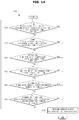
- FIG. 12 is a flowchart illustrating an ice making operation of a refrigerator according to an embodiment
- FIG. 13 is a flowchart illustrating an example of an ice agglomeration preventing operation of a refrigerator according to an embodiment
- FIG. 14 is a flowchart illustrating another example of an ice agglomeration preventing operation of a refrigerator according to an embodiment
- FIG. 15 is a flowchart illustrating another example of an ice agglomeration preventing operation of a refrigerator according to an embodiment
- FIGS. 16 and 17 are views illustrating an example in which a refrigerator according to an embodiment prevents ice agglomeration
- FIG. 18 is a flowchart illustrating an example of an ice agglomeration warning operation of a refrigerator according to an embodiment
- FIGS. 19 and 20 are views illustrating an example in which a refrigerator according to an embodiment warns of ice agglomeration.
- FIG. 21 is a flowchart illustrating another example of an ice agglomeration warning operation of a refrigerator according to an embodiment.
- FIGS. 1 through 21 discussed below, and the various embodiments used to describe the principles of the present disclosure in this patent document are by way of illustration only and should not be construed in any way to limit the scope of the disclosure. Those skilled in the art will understand that the principles of the present disclosure may be implemented in any suitably arranged system or device.
- FIG. 1 shows an outer appearance of a refrigerator according to an embodiment.
- FIG. 2 shows the inside of a refrigerator according to an embodiment.
- FIG. 3 illustrates a side vertical-sectional view of a refrigerator according to an embodiment.
- a refrigerator 1 may include a main body 10 whose front portion opens, a storage room 20 formed in the inside of the main body 10 and configured to refrigerate and/or freeze food, a door 30 configured to open or close the open front portion of the main body 10 , a cooling apparatus 50 configured to freeze the storage room 20 , and an ice making apparatus 60 configured to make ice cubes.
- the main body 10 may form an outer appearance of the refrigerator 1 .
- the main body 10 may include an inner case 11 forming the storage room 20 , and an outer case 12 coupled with an outer portion of the inner case 11 .
- An insulator 13 may be foamed between the inner case 11 and the outer case 12 of the main body 10 in order to prevent cool air from escaping from the storage room 20 .
- the storage room 20 may be partitioned into a plurality of rooms by a horizontal wall 21 and a vertical wall 22 .
- the storage room 20 may be partitioned into an upper storage room 20 a , a first lower storage room 20 b , and a second lower storage room 20 c .
- the upper storage room 20 a may refrigerate food
- the lower storage rooms 20 b and 20 c may freeze food.
- one or more shelves 23 may be provided to put food thereon.
- the number and arrangement of the storage room 20 are not limited to the embodiment shown in FIG. 2 .
- the storage room 20 may be opened or closed by the door 30 .
- the upper storage room 20 a may be opened or closed by a first upper door 30 aa and a second upper door 30 ab .
- the first lower storage room 20 b may be opened or closed by a first lower door 30 b
- the second lower storage room 20 c may be opened or closed by a second lower door 30 c.
- a handle 31 may be installed on the door 30 to enable a user to easily open or close the door 30 .
- the handle 31 may extend longitudinally along between the first upper door 30 aa and the second upper door 30 ab and between the first lower door 30 b and the second lower door 30 c . As a result, when the door 30 is closed, the handle 31 may look as if it is one body with the door 30 .
- the number and arrangement of the door 30 are not limited to the embodiment shown in FIG. 2 .
- a dispenser 40 may be provided in an area of the door 30 .
- the dispenser 40 may discharge water and/or ice cubes in response to a user's input. In other words, the user may take water and/or ice cubes through the dispenser 40 without having to open the door 30 .
- the dispenser 40 may include a dispenser lever 41 to which a user's discharge instruction is input, a dispenser chute 42 through which ice cubes are discharged from the ice making apparatus 60 , and a dispenser display panel 43 displaying an operation state of the dispenser 40 .
- the dispenser 40 may be installed in the door 30 or in an outer area of the main body 10 .
- the dispenser 40 may be installed in the first upper door 30 aa .
- the position of the dispenser 40 is not limited to the first upper door 30 aa . That is, the dispenser 40 may be positioned at any other location at which the user can take water and/or ice cubes, such as the second upper door 30 ab , the first lower door 30 b , the second lower door 30 c , and the outer case 12 of the main body 10 .
- the cooling apparatus 50 may include, as shown in FIG. 3 , a compressor 51 to compress refrigerants to high pressure, a condenser 52 to condense the compressed refrigerants, an expander 54 and 55 to expand the refrigerants to low pressure, an evaporator 56 and 57 to evaporate the refrigerants, and a refrigerant pipe 58 to guide the refrigerants.
- the compressor 51 and the condenser 52 may be located in a machine room 14 provided in rear, lower space of the main body 10 .
- the evaporator 56 and 57 may include a first evaporator 56 to supply cool air to the upper storage room 20 a , and a second evaporator 57 to supply cool air to the lower storage rooms 20 b and 20 c .
- the first evaporator 56 may be disposed in a first cool-air duct 56 a formed in rear space of the upper storage room 20 a
- the second evaporator 57 may be disposed in a second cool-air duct 57 a formed in rear space of the lower storage rooms 20 b and 20 c.
- a first blow fan may be disposed to supply cool air generated by the first evaporator 56 to the upper storage room 20 a
- a second blow fan may be disposed to supply cool air generated by the second evaporator 57 to the lower storage rooms 20 b and 20 c.
- the refrigerant pipe 58 may guide refrigerants compressed by the compressor 51 to the first evaporator 56 and the second evaporator 57 or to the ice making apparatus 60 .
- a switching valve 53 may be installed to distribute refrigerants to the first evaporator 56 or the second evaporator 57 or to the ice making apparatus 60 .
- a portion (hereinafter, also referred to as an “ice making refrigerant pipe”) 59 of the refrigerant pipe 58 may extend to the inside of the ice making apparatus 60 , and the ice making refrigerant pipe 59 disposed in the inside of the ice making apparatus 60 may freeze water contained in the ice making apparatus 60 to make ice cubes.
- the ice making apparatus 60 may make ice cubes using cool air supplied from the ice making refrigerant pipe 59 , and may be disposed in the storage room 20 .
- the ice making apparatus 60 may be disposed in a left, upper area of the upper storage room 20 a to correspond to the dispenser 40 installed in the first upper door 30 aa.
- the location of the ice making apparatus 60 is not limited to the embodiment shown in FIG. 2 , and the ice making apparatus 60 may be installed in the lower storage rooms 20 b and 20 c or in the horizontal wall 21 between the upper storage room 20 a and the lower storage rooms 20 b and 20 c.
- FIG. 4 illustrates a side vertical-sectional view of an ice making apparatus included in a refrigerator according to an embodiment.
- FIG. 5 shows an outer appearance of an ice maker included in a refrigerator according to an embodiment.
- FIG. 6 illustrates an exploded perspective view of an ice maker included in a refrigerator according to an embodiment.
- FIG. 7 illustrates a sectional view of an ice maker included in a refrigerator according to an embodiment when the ice maker discharges ice cubes.
- FIG. 8 shows an outer appearance of an ice storage included in a refrigerator according to an embodiment.
- FIG. 9 illustrates an exploded perspective view of an ice storage included in a refrigerator according to an embodiment.
- FIG. 10 illustrates a sectional view of an ice storage included in a refrigerator according to an embodiment when the ice storage discharges ice cubes.
- the ice making apparatus 60 may include an ice maker 100 and an ice storage 200 .
- the ice maker 100 may make ice cubes, and discharge the ice cubes to the ice storage 200 .
- the ice storage 200 may store the ice cubes made by the ice maker 100 .
- the ice storage 200 may discharge the stored ice cubes through the dispenser 40 in response to a user instruction input through the dispenser lever 41 .
- the ice storage 200 may discharge ice cubes to the outside through the dispenser 40 .
- the ice maker 100 may include an ice making tray 110 which stores water for making ice cubes and in which ice cubes are made, an ice discharging portion 120 configured to separate the ice cubes made in the ice making tray 110 from the ice making tray 110 , an ice discharging motor 130 configured to rotate the ice discharging portion 120 , an ice making cover 150 guiding the ice cubes separated from a first ice making tray 111 to the ice storage 200 , a slider 160 configured to prevent the ice cubes separated from the ice making tray 110 from returning to the first ice making tray 111 , an ice discharging heater 170 configured to heat the ice making tray 110 to separate the ice cubes from the ice making tray 110 , and a cool air duct 140 guiding cool air from the ice making refrigerant pipe 59 to the ice storage 200 .
- the ice making tray 110 may include the first ice making tray 111 storing water for making ice cubes, and a second ice making tray 112 contacting the ice making refrigerant pipe 59 .
- the first ice making tray 111 may include a plurality of ice making cells 110 a , and each ice making cell 110 a may store water for making an ice cube. Also, the first ice making tray 111 may be rested on the second ice making tray 112 , and cooled by the second ice making tray 112 .
- the second ice making tray 112 may be made of a material having high heat conductivity, and below the second ice making tray 112 , the ice making refrigerant pipe 59 may be positioned.
- the ice making tray 110 may be cooled to below the freezing point (zero degrees Celsius) of water by the ice making refrigerant pipe 59 .
- the second ice making tray 112 may cool the first ice making tray 111 , and water stored in the ice making cells 110 a of the first ice making tray 111 may be frozen to make ice cubes.
- the ice discharging portion 120 may be positioned above the ice making tray 110 , and after ice cubes are made, the ice discharging portion 120 may separate the ice cubes from the ice making tray 110 .
- the ice discharging portion 120 may include a scooping shaft 121 that is rotatable, and a scooping blade 122 configured to separate ice cubes from the ice making tray 110 .
- the scooping shaft 121 may pass through a through hole of the ice making tray 110 to be positioned above the ice making tray 110 .
- the scooping shaft 121 may be installed at an appropriate height from the ice making tray 110 such that at least one of the scooping blade 122 can be located in the ice making cells 110 a when the scooping blade 122 is located downward.
- the scooping shaft 121 may be connected to the ice discharging motor 130 , and receive a rotational force from the ice discharging motor 130 to rotate in a clockwise or counterclockwise direction.
- the scooping blade 122 may protrude from a side wall of the scooping shaft 121 .
- the number of the plurality of scooping blades 122 may be equal to that of the plurality of ice making cells 110 a of the ice making tray 110 , and the locations of the plurality of scooping blades 122 may correspond to those of the plurality of ice making cells 110 a.
- the scooping blades 122 may rotate on the scooping shaft 121 when the scooping shaft 121 rotates, and when the scooping blades 122 rotate, at least one of the scooping blades 122 may be positioned in the ice making cells 110 a.
- the scooping blades 122 When the scooping blades 122 rotate, the scooping blades 122 may separate ice cubes made in the ice making tray 110 from the ice making tray 110 . More specifically, when the scooping blades 122 rotate in the clockwise or counterclockwise direction on the scooping shaft 121 , the scooping blades 122 may separate ice cubes from the ice making tray 110 , and push the ice cubes out of the ice making tray 110 .
- the scooping blades 122 may rotate in the clockwise direction on the scooping shaft 121 . Also, when the scooping blades 122 rotate in the clockwise direction, the scooping blades 122 may raise ice cubes I in the clockwise direction.
- the ice discharging motor 130 may generate a rotational force to rotate the ice discharging portion 120 in the clockwise or counterclockwise direction.
- the ice discharging motor 130 may be connected to the scooping shaft 121 of the ice discharging portion 120 , and a rotational force of the ice discharging motor 130 may be transferred to the scooping shaft 121 of the ice discharging portion 120 .
- the ice discharging motor 130 may rotate at 1 rpm (revolution per minute) to 6 rpm to enable the scooping blades 122 to separate the ice cubes I from the ice making tray 110 .
- the ice discharging motor 130 may rotate about 360 degrees such that the scooping blades 122 make one full revolution on the scooping shaft 121 .
- the ice discharging motor 130 may include a Direct Current (DC) motor rotating in response to supply of DC power, an Alternating Current (AC) motor rotating in response to supply of AC power, or a step motor rotating in response to supply of a plurality of pulses.
- DC Direct Current
- AC Alternating Current
- step motor rotating in response to supply of a plurality of pulses.
- the ice making cover 150 may guide the ice cubes I separated from the ice making tray 110 to the ice storage 200 .
- an inner wall 151 of the ice making cover 150 may extend from inside surfaces of the ice making cells 110 a of the ice making tray 110 , and have a curved surface for guiding the ice cubes I to the ice storage 200 .
- the slider 160 may include a plurality of guide protrusions 161 protruding from the ice making tray 110 toward the scooping shaft 121 of the ice discharging portion 120 .
- Spaces between the plurality of guide protrusions 161 may be wider than widths of the scooping blades 122 so that the scooping blades 122 can pass through the spaces between the plurality of guide protrusions 161 .
- the spaces between the plurality of guide protrusions 161 may be narrower than widths of the ice making cells 110 a so that the ice cubes I cannot pass through the spaces between the plurality of guide protrusions 161 . Accordingly, the guide protrusions 161 of the slider 160 may not interfere with a rotation of the scooping blades 122 , and may not pass the ice cubes I through.
- the ice cubes I raised by the scooping blades 122 may be guided to the slider 160 along the inner wall 151 of the ice making cover 150 .
- the ice cubes I may fall downward along the guide protrusions 161 of the slider 160 , without passing through the guide protrusions 161 .
- the ice cubes I may be put into the ice storage 200 along the guide protrusions 161 .
- the ice making refrigerant pipe 59 may have a “U” shape, and directly contact a lower surface of the second ice making tray 112 .
- the second ice making tray 112 may be cooled by contacting the ice making refrigerant pipe 59 .
- the ice discharging heater 170 may directly contact the lower surface of the second ice making tray 112 to directly heat the second ice making tray 112 .
- the ice discharging heater 170 may heat the ice making tray 110 in order to smoothly separate ice cubes from the ice making tray 110 .
- the ice making tray 110 is heated, a part of ice cubes contacting the ice making tray 110 may melt, and accordingly, the ice cubes can easily move along the inner wall of the ice making tray 110 .
- the ice discharging heater 170 may be used to defrost the ice making refrigerant pipe 59 .
- frost may be formed on the surface of the ice making refrigerant pipe 59 .
- the frost formed on the surface of the ice making refrigerant pipe 59 may reduce heat-exchange efficiency of the ice making refrigerant pipe 59 .
- the refrigerator 1 may operate the ice discharging heater 170 to remove frost formed on the surface of the ice making refrigerator pipe 59 .
- Inside air of the cool air duct 140 may be cooled by the ice making refrigerant pipe 59 and/or the ice making tray 110 .
- the air cooled by the ice making refrigerant pipe 59 and/or the ice making tray 110 may flow to the ice storage 200 along the inside of the cool air duct 125 , that is, along the cool air path 141 . Due to the cool air entered the ice storage 200 , the ice storage 200 can be maintained at below zero temperatures, and ice cubes stored in the ice storage 200 may not melt.
- the ice storage 200 may include an ice bucket 210 storing ice cubes made by the ice maker 100 , a transfer member 220 configured to transfer the ice cubes stored in the ice bucket 210 to an outlet 211 , a transfer motor 230 configured to drive the transfer member 220 , a crusher 240 configured to selectively crush ice cubes discharged to the outlet 211 , and an ice storage fan 250 to circulate inside air of the ice maker 100 and the ice storage 200 .
- the ice bucket 210 may be positioned below the ice maker 100 , and form an ice storage room 210 a in which ice cubes can be stored. Ice cubes separated from the ice making tray 110 by the ice discharging portion 120 may be stored in the ice storage room 210 a.
- the ice cubes may be separated from the ice making tray 110 by the ice discharging portion 120 , and then fall into the ice bucket 210 .
- the ice cubes fallen into the ice bucket 210 may be stored in the ice bucket 210 until an ice discharge instruction is input by a user.
- an outlet 211 may be formed to discharge the ice cubes from the ice bucket 210 .
- the transfer member 220 may be disposed in the inside of the ice bucket 210 , that is, in the ice storage room 210 a to transfer the ice cubes stored in the ice bucket 210 toward the outlet 211 of the ice bucket 210 .
- the transfer member 220 may be in the shape of an auger.
- the transfer member 220 may include a transfer shaft 221 that is rotatable in the clockwise or counterclockwise direction, and a transfer member 220 that is formed in a spiral shape along the outer surface of the transfer shaft 221 .
- the transfer member 220 may be a wire formed in a spiral shape.
- the ice cubes stored in the ice bucket 210 may be transferred to the outlet 211 or in the opposite direction from the outlet 211 .
- the transfer member 220 including the transfer shaft 221 and the spiral transfer blade 222 is shown.
- the transfer member 220 may include a wire formed in a spiral shape.
- the transfer member 220 including a spiral wire may also transfer ice cubes toward the outlet 211 or in the opposite direction from the outlet 211 , according to a rotation direction.
- the transfer motor 230 may rotate the transfer member 220 in the first rotation direction or in the second rotation direction.
- the transfer motor 230 may rotate in the first rotation direction.
- the transfer member 220 may transfer the ice cubes I stored in the ice bucket 210 in the opposite direction from the outlet 211 .
- an external force may be applied to the ice cubes I, and ice cubes agglomerated in the ice storage room 210 a may be separated by the external force.
- the ice cubes stored in the ice storage room 210 a may be stuck together due to various causes, and as a result, the ice cubes may agglomerate together.
- the surfaces of ice cubes may melt due to friction between the ice cubes so that the ice cubes agglomerate together, or when ice cubes are separated from the ice making tray 110 , the surfaces of the ice cubes may melt to agglomerate with ice cubes stored in the ice storage room 210 a.
- air between ice cubes may be frozen by sublimation of the ice cubes so that the ice cubes agglomerate together.
- the water vapor between ice cubes may sublimate (water vapor ⁇ ice) so that the ice cubes are stuck together to agglomerate.
- the transfer member 220 may transfer the ice cubes stored in the ice bucket 210 in the opposite direction from the outlet 211 to thereby separate cubed ice from the agglomerated ice cubes. Separating the cubed ice from the agglomerated ice cubes may be different from crushing ice cubes through the crusher 240 which will be described later. Separating ice cubes through the transfer member 220 means separating agglomerated ice cubes in order to maintain the state of cubed ice, and crushing ice cubes through the crusher 240 means crushing cubed ice to crushed ice.
- the transfer motor 230 may output information about a rotation when it rotates.
- the transfer motor 230 may output information about a rotation direction (for example, the first rotation direction or the second rotation direction) or information about rpm.
- the transfer motor 230 may output information about driving current when it rotates.
- the transfer motor 230 may be a DC motor rotating in response to supply of DC power, an AC motor rotating in response to supply of AC power, or a step motor rotating in response to supply of a plurality of pulses.
- the crusher 240 may include a plurality of crush blades 241 configured to crush ice cubes, and a crush cover 242 surrounding the plurality of crush blades 241 .
- the crush blades 241 may crush ice cubes discharged through the outlet 211 .
- the ice making apparatus 60 may discharge cubed ice or crushed ice according to a user's selection.
- the ice cubes may be discharged without being crushed by the crush blades 241 .
- ice cubes made in the ice making cells 110 a of the ice making tray 110 may be discharged, as they are in the shape of the ice making cells 110 a , to the outside through the dispenser 40 .
- the ice cubes may be crushed by the crush blades 241 , and then discharged. More specifically, ice cubes passed through the outlet 211 may be crushed by the crush blades 241 , and then discharged to the outside through the dispenser 40 .
- the crush cover 242 may accommodate the crush blades 241 so that the crush blades 241 are not exposed to the outside.
- an outlet 242 a may be provided below the crush cover 242 to discharge ice cubes. Ice cubes crushed by the crush blades 241 may be discharged through the outlet 242 a of the crush cover 242 .
- the ice storage fan 250 may circulate cool air in the cool air duct 125 to the ice bucket 210 .
- the ice storage fan 250 may inhale air in the ice bucket 210 , and discharge the inhaled air to the cool air duct 125 , as shown in FIG. 4 .
- the air may be cooled by the ice making refrigerant pipe 59 and/or the ice making tray 110 in the inside of the cool air duct 125 , and then, the cooled air may again flow to the ice bucket 210 .
- inside air of the ice storage 200 can be maintained at below zero temperatures.
- the ice maker 100 may make ice cubes, and the ice storage 200 may store the ice cubes made by the ice maker 100 .
- the ice storage 200 may discharge the ice cubes according to the user's selection.
- the ice storage 200 may apply an external force to the ice cubes using the transfer member 220 in order to prevent the stored ice cubes from agglomerating together.
- FIG. 11 shows a control configuration of a refrigerator according to an embodiment.
- the refrigerator 1 may further include, in addition to the components shown in FIGS. 1 to 10 , a storage room temperature sensor 320 configured to measure temperature of the storage room 20 , an ice making temperature sensor 330 configured to measure temperature of the ice making apparatus 60 , the dispenser lever 41 to which an ice discharge instruction is input, the cooling apparatus 50 configured to cool the storage room 20 , the ice making apparatus 60 to make and store ice cubes, a speaker 340 configured to output sound, and a controller 310 configured to control the cooling apparatus 50 according to an output of the storage room temperature sensor 320 , and to control the ice making apparatus 60 according to an output of the ice making temperature sensor 330 .
- a storage room temperature sensor 320 configured to measure temperature of the storage room 20
- an ice making temperature sensor 330 configured to measure temperature of the ice making apparatus 60
- the dispenser lever 41 to which an ice discharge instruction is input
- the cooling apparatus 50 configured to cool the storage room 20
- the ice making apparatus 60 to make and store ice cubes
- the upper storage room temperature sensor 321 may be installed in the upper storage room 20 a to measure temperature of the upper storage room 20 a and to output an electrical signal corresponding to the temperature of the upper storage room 20 a to the controller 310 .
- the upper storage room temperature sensor 321 may be a thermistor whose electrical resistance value changes according to temperature.
- the lower storage room temperature sensor 322 may be installed in the lower storage room 20 b to measure temperature of the lower storage room 20 b and to output an electrical signal corresponding to the temperature of the lower storage room 20 b to the controller 310 .
- the lower storage room temperature sensor 322 may be a thermistor whose electrical resistance value changes according to temperature.
- the ice making temperature sensor 330 may be installed in the ice making apparatus 60 .
- the ice making temperature sensor 330 may be installed in the ice making tray 110 in which water for making ice cubes is stored.
- the ice making temperature sensor 330 may measure temperature of water or ice cubes accommodated in the ice making tray 110 , and output an electrical signal corresponding to the temperature of the water or ice cubes to the controller 310 .
- the ice making temperature sensor 330 may be a thermistor whose electrical resistance value changes according to temperature.
- the dispenser lever 41 may be installed in the door 30 , and a user's instruction for discharging ice cubes may be input to the dispenser lever 41 . For example, if the dispenser lever 41 is pressed by the user, the ice making apparatus 60 may discharge ice cubes to the outside through the dispenser 40 .
- the compressor 51 may compress refrigerants to high pressure in response to a control signal from the controller 310 , and discharge the compressed refrigerants to the condenser 52 .
- the switching valve 53 may supply refrigerants to at least one of the evaporator 56 of the upper storage room 20 a and the evaporator 57 of the lower storage room 20 b in response to a control signal from the controller 310 .
- the compressor 51 may generate the flow of refrigerants in response to a control signal from the controller 310 , and the switching valve 53 may control a flow path of the refrigerants.
- the ice making apparatus 60 may include the ice maker 100 for making ice cubes, and the ice storage 200 storing the ice cubes.
- the ice maker 100 may include the ice making tray 110 , the ice discharging portion 120 , the ice discharging motor 130 , the ice making cover 150 , the slider 160 , the ice discharging heater 170 , and the cool air duct 140 .
- the ice storage 200 may include the ice bucket 210 , the transfer member 220 , the crusher 240 , and the ice storage fan 250 .
- the ice discharging motor 130 may drive the ice discharging portion 120 in response to a control signal from the controller 310 to separate ice cubes from the ice making tray 110 .
- the transfer motor 230 may drive the transfer member 220 in response to a control signal from the controller 310 to discharge ice cubes.
- the speaker 340 may output sound corresponding to an electrical sound signal output from the controller 310 . More specifically, the speaker 340 may receive an electrical sound signal from the controller 310 , and convert the electrical sound signal to sound.
- the controller 310 may include memory 312 storing programs and data for controlling operations of the refrigerator 1 , and a processor 311 configured to generate control signals for controlling the operations of the refrigerator 1 according to the programs and data stored in the memory 312 .
- the processor 311 and the memory 312 may be implemented as separate chips or as a signal chip.
- the memory 312 may store control programs and control data for controlling operations of the refrigerator 1 , and various application programs and application data for performing various functions according to a user's inputs. Also, the memory 312 may temporarily store an output of the storage room temperature sensor 320 , an output of the ice making temperature sensor 330 , and an output of the processor 311 .
- the memory 312 may include volatile memory, such as Static-Random Access Memory (S-RAM) and Dynamic-Random Access Memory (D-RAM), for temporarily storing data. Also, the memory 312 may include non-volatile memory, such as Read Only Memory (ROM), Erasable Programmable Read Only Memory (EPROM), and Electrically Erasable Programmable Read Only Memory (EEPROM), for storing data for a long time.
- volatile memory such as Static-Random Access Memory (S-RAM) and Dynamic-Random Access Memory (D-RAM)
- D-RAM Dynamic-Random Access Memory
- ROM Read Only Memory
- EPROM Erasable Programmable Read Only Memory
- EEPROM Electrically Erasable Programmable Read Only Memory
- the processor 311 may include various logic circuits and operation circuits, and process data according to a program provided from the memory 312 , and generate a control signal according to the result of the processing.
- the processor 311 may process an output of the storage room temperature sensor 320 , and generate a cooling control signal for controlling the compressor 51 and the switching valve 53 of the cooling apparatus 50 in order to cool the storage room 20 .
- the processor 311 may process an output of the ice making temperature sensor 330 , and generate an ice making control signal for controlling the ice discharging motor 130 and the ice discharging heater 170 of the ice making apparatus 60 .
- the processor 311 may process an output of the dispenser lever 41 , and generate an ice discharge control signal for controlling the transfer motor 230 of the ice making apparatus 60 in order to discharge ice cubes.
- the controller 310 may control the components included in the refrigerator 1 according to temperature of the storage room 20 , temperature of the ice making apparatus 60 , and an operation of the ice making apparatus 60 .
- operations of the refrigerator 1 may be performed according to the control of the controller 310 .
- FIG. 12 is a flowchart illustrating an ice making operation of a refrigerator according to an embodiment.
- the refrigerator 1 may supply water to the ice making tray 110 , in operation 1010 .
- the controller 310 of the refrigerator 1 may open a water supply valve (not shown) to supply water to the ice making tray 110 . Water may be supplied to the plurality of ice making trays 110 , sequentially.
- the refrigerator 1 may cool the ice making tray 110 , in operation 1020 .
- the controller 310 of the refrigerator 1 may operate the compressor 51 of the cooling apparatus 50 to make a flow of refrigerants, and control the switching valve 53 to supply the refrigerants to the ice making refrigerant pipe 59 .
- the compressor 51 may compress refrigerants of a liquid state, and discharge the refrigerants.
- the refrigerants discharged from the compressor 51 may enter the switching valve 53 via the condenser 52 .
- the refrigerants may be guided to the ice making refrigerant pipe 59 via the expander 55 by the switching valve 53 .
- the refrigerants may be vaporized when passing through the ice making refrigerant pipe 59 , and when the refrigerants are vaporized, the ice making tray 110 (for example, the second ice making tray) may be cooled. Thereafter, the refrigerants may enter the compressor 51 via the evaporator 57 of the lower storage room 20 b.
- the refrigerants may be circulated by the compressor 51 . Also, when the refrigerants are circulated, the refrigerants may absorb heat from the ice making tray 110 , and cool the ice making tray 110 .
- the refrigerator 1 may determine whether temperature of water or ice cubes contained in the ice making tray 110 is lower than reference temperature, in operation 1030 .
- the water contained in the ice making tray 110 may also be cooled.
- the second ice making tray 112 contacting the ice making refrigerant pipe 59 may be cooled by the ice making refrigerant pipe 59
- the first ice making tray 111 contacting the second ice making tray 112 may be cooled accordingly.
- water stored in the ice making cells 110 a of the first ice making tray 111 may be cooled and frozen.
- the ice making temperature sensor 330 installed in the ice making tray 110 may measure temperature of water and/or ice cubes contained in the ice making tray 110 .
- the controller 310 may determine freezing of the water contained in the ice making tray 110 based on an output from the ice making temperature sensor 330 .
- the water When water starts being frozen, the water may be maintained at temperature of about zero degrees Celsius, and when the water is completely frozen, temperature of ice may be lowered to below zero degrees Celsius. Also, if the temperature of the ice is sufficiently low (about 10 degrees to 20 degrees below zero Celsius), the ice will not melt easily despite a change in ambient temperature.
- the reference temperature may be set within 5 degrees to 20 degrees below zero Celsius.
- the refrigerator 1 may repeatedly measure temperature of the water or ice cubes contained in the ice making tray 110 .
- the refrigerator 1 may separate the ice cubes from the ice making tray 110 , and store the ice cubes in the ice bucket 210 , in operation 1040 .
- the controller 310 of the refrigerator 1 may separate the ice cubes from the ice making tray 110 , and store the separated ice cubes in the ice bucket 210 , in order to make new ice cubes.
- the controller 310 may drive the ice discharging heater 170 in order to separate the ice cubes from the ice making tray 110 .
- the ice discharging heater 170 may heat the ice making tray 110 , and a part of the ice cubes contacting the ice making tray 110 may melt. As a result, a water screen may be formed between the ice cubes and the ice making tray 110 , and accordingly, the ice cubes can move smoothly on the ice making tray 110 .
- the controller 310 may control the ice discharging motor 130 to cause the scooping blade 122 of the ice discharging portion 120 to push the ice cubes out of the ice making tray 110 .
- the ice discharging motor 130 may rotate the ice discharging portion 120 to cause the scooping blade 122 to push the ice cubes out of the ice making tray 110 .
- the refrigerator 1 may make ice cubes using the ice maker 100 , and store the ice cubes in the ice storage 200 .
- the refrigerator 1 may discharge the ice cubes stored in the ice storage 200 to the outside in response to a user's discharge instruction input through the dispenser lever 41 .
- the controller 310 may control the transfer motor 230 so that the transfer member 220 transfers the ice cubes toward the outlet 211 of the ice bucket 210 .
- the controller 310 may control the transfer motor 230 such that the transfer member 220 rotates in the second rotation direction (the counterclockwise direction of FIGS. 8, 9, and 10 ). In other words, the controller 310 may rotate the transfer motor 230 in the second rotation direction.
- the ice cubes may be transferred toward the outlet 211 , and then discharged through the dispenser 40 .
- the refrigerator 1 may discharge ice cubes stored in the ice storage 200 to the outside in response to the user's discharge instruction.
- the ice cubes stored in the ice storage room 210 a may be stuck or agglomerate together due to various causes.
- the refrigerator 1 may perform an operation for preventing ice cubes stored in the ice storage room 210 a from agglomerating together.
- FIG. 13 is a flowchart illustrating an example of an ice agglomeration preventing operation of a refrigerator according to an embodiment.
- the ice cubes stored in the ice bucket 210 may be stuck or agglomerate together due to various causes.
- the agglomerated ice cubes may be not transferred by the transfer member 220 .
- the agglomerated ice cubes may be not discharged to the outside by the transfer member 220 .
- the refrigerator 1 may prevent ice agglomeration.
- the controller 310 of the refrigerator 1 may determine a condition under which ice cubes stored in the ice bucket 210 agglomerate. For example, the controller 310 may determine a condition under which ice cubes agglomerate easily, based on an operation of the transfer motor 230 , an operation of the dispenser 40 , an operation of the compressor 51 , an operation of the ice storage fan 250 , the number of times the door 300 opens, a defrosting operation of the ice making refrigerant pipe 59 , etc.
- the refrigerator 1 may perform an operation for preventing ice agglomeration, in operation 1120 .
- the ice cubes stored in the ice bucket 210 may be predicted to agglomerate.
- the refrigerator 1 may perform an operation for preventing the ice cubes stored in the ice bucket 210 from agglomerating or for delaying agglomeration of the ice cubes.
- the refrigerator 1 may apply a physical force to the ice cubes to prevent the ice cubes from agglomerating.
- the controller 310 of the refrigerator 1 may rotate the transfer member 220 in the first rotation direction and/or in the second rotation direction to prevent the ice cubes from agglomerating.
- the controller 310 may operate the transfer motor 230 to rotate the transfer member 220 in the first rotation direction and/or in the second rotation direction.
- the transfer member 220 rotates, the ice cubes stored in the ice bucket 210 may move separately, and accordingly, the sticking of the ice cubes may be broken. As a result, it is possible to prevent the ice cubes stored in the ice bucket 210 from agglomerating.
- FIG. 14 is a flowchart illustrating another example of an ice agglomeration preventing operation of a refrigerator according to an embodiment.
- the refrigerator 1 may determine whether a time period elapsed after an ice agglomeration preventing operation is longer than a first reference time period, in operation 1210 .
- the refrigerator 1 may perform an ice agglomeration preventing operation for preventing ice agglomeration.
- the controller 310 of the refrigerator 1 may operate the transfer motor 230 such that the transfer member 220 rotates in the first rotation direction and/or in the second rotation direction.
- the transfer member 220 rotates, ice cubes stored in the ice bucket 210 may move, and accordingly, the sticking of the ice cubes may be broken.
- the ice cubes stored in the ice bucket 210 may be again stuck together over time to agglomerate together.
- the refrigerator 1 may determine whether the first reference time period has elapsed after the ice agglomeration preventing operation is performed, in order to determine whether the ice cubes stored in the ice bucket 210 are again stuck together.
- the controller 310 of the refrigerator 1 may determine whether the first reference time period has elapsed after the transfer motor 230 operated.
- the first reference time period may be a time period taken for ice cubes to be stuck together by sublimation of ice, and may be set within about 12 hours to about 72 hours.
- the refrigerator 1 may perform an operation for preventing ice agglomeration, in operation 1270 .
- the refrigerator 1 may again perform an ice agglomeration preventing operation. More specifically, when the first reference time period has elapsed after the transfer motor operated in order to prevent ice agglomeration, the controller 310 may operate the transfer motor 230 such that the transfer member 220 rotates in the first rotation direction and/or in the second rotation direction.
- the refrigerator 1 may determine whether a time period elapsed after an ice discharge operation is longer than a second reference time period, in operation 1220 .
- the refrigerator 1 may discharge ice cubes stored in the ice bucket 210 in response to a user's ice discharge instruction input through the dispenser lever 41 .
- the controller 310 of the refrigerator 1 may operate the transfer motor 230 such that the transfer member 220 rotates in the second rotation direction.
- the transfer member 220 rotates, the ice cubes stored in the ice bucket 210 may move toward the outlet 211 , and be discharged through the dispenser 40 .
- the transfer member 220 rotates, the sticking of the ice cubes stored in the ice bucket 210 may be broken, and accordingly, ice agglomeration can be prevented.
- ice agglomeration is prevented when ice cubes are discharged, ice cubes stored in the ice bucket 210 may be again stuck together over time to agglomerate.
- the refrigerator 1 may determine whether the second reference time period has elapsed after the dispenser lever 41 was pressed, in order to determine whether the ice cubes stored in the ice bucket 210 are again stuck together.
- the controller 310 of the refrigerator 1 may determine whether the second reference time period has elapsed after the dispenser lever 41 was pressed.
- the second reference time period may be a time period taken for ice cubes to be stuck together by sublimation of ice, etc., and may be set within about 12 hours to about 72 hours.
- the refrigerator 1 may perform an operation for preventing ice agglomeration, in operation 1270 .
- the refrigerator 1 may perform an ice agglomeration preventing operation. More specifically, when the second reference time period has elapsed after the dispenser lever 41 for discharging ice cubes was pressed, the controller 310 may operate the transfer motor 230 such that the transfer member 220 rotates in the first rotation direction and/or in the second rotation direction.
- the refrigerator 1 may determine whether an operation time period of the compressor 51 is longer than a third reference time period, in operation 1230 .
- Ice agglomeration may accelerate when the compressor 51 operates.
- the compressor 51 operates, and refrigerants are supplied to the ice making refrigerant pipe 59 , inside temperature of the ice storage 200 may be further lowered.
- sublimation of water vapor in the inside of the ice storage 200 may accelerate, and also, agglomeration of ice cubes stored in the ice bucket 210 may accelerate accordingly.
- the refrigerator 1 may determine whether a time period for which the compressor 51 operates after the ice agglomeration preventing operation or the ice discharge operation is longer than the third reference time period, in order to determine whether agglomeration of ice cubes stored in the ice bucket 210 accelerates.
- the controller 310 may measure a time period for which the compressor 51 operates after the transfer motor 230 operates for an ice agglomeration preventing operation or an ice discharge operation, and compare the operation time period of the compressor 51 to the third reference time period.
- the third reference time period may be a time period for which agglomeration of ice cubes accelerates by sublimation of ice, etc., and may be set within about 3 hours to about 6 hours.
- the refrigerator 1 may perform an operation for preventing ice agglomeration, in operation 1270 .
- the refrigerator 1 may perform an ice agglomeration preventing operation.
- controller 310 may operate the transfer motor 230 such that the transfer member 220 rotates in the first rotation direction and/or in the second rotation direction.
- the refrigerator 1 may determine whether an operation time period of the ice storage fan 250 is longer than a fourth reference time period, in operation 1240 .
- the ice storage fan 250 may circulate cool air in the cool air duct 125 to the ice bucket 210 .
- the ice storage fan 250 may operate when the compressor 51 operates. Also, the ice storage fan 250 may stop when the compressor 51 stops, or when a predetermined time period has elapsed after the compressor 51 stopped. As such, operating or stopping the ice storage fan 250 may be synchronized with operating or stopping the compressor 51 .
- ice agglomeration may accelerate. More specifically, when the compressor 51 operates and the ice storage fan 250 operates, sublimation of water vapor in the ice storage 200 may accelerate, and also, agglomeration of ice cubes stored in the ice bucket 210 may accelerate accordingly.
- the refrigerator 1 may determine whether a time period for which the ice storage fan 250 operates after an ice agglomeration preventing operation or an ice discharge operation is longer than a fourth reference time period, in order to determine whether agglomeration of the ice cubes stored in the ice bucket 210 accelerates.
- the controller 310 may measure an operation time period of the ice storage fan 250 after the transfer motor 230 operates for an ice agglomeration preventing operation or an ice discharge operation, and compare the operation time period of the ice storage fan 250 to the fourth reference time period.
- the fourth reference time period may be a time period for which agglomeration of ice cubes accelerates by sublimation of ice, etc., and may be set within about 3 hours to about 6 hours.
- the refrigerator 1 may perform an operation for preventing ice agglomeration, in operation 1270 .
- the refrigerator 1 may perform an ice agglomeration preventing operation. More specifically, the controller 310 may operate the transfer motor 230 such that the transfer member 220 rotates in the first rotation direction and/or in the second rotation direction.
- the refrigerator 1 may determine whether the number of times the door 30 opens is greater than a first reference number of times, in operation 1250 .
- temperature of the storage room 20 may rise. If the temperature of the storage room 20 rises, an operation time period of the compressor 51 may increase. If the operation time period of the compressor 51 increases, sublimation of water vapor in the ice bucket 210 may accelerate, and accordingly, ice agglomeration may accelerate.
- an amount of water vapor entering the storage room 20 or the ice making apparatus 60 from the outside may increase. If the amount of water vapor entering the ice making apparatus 60 increases, sublimation of water vapor in the ice bucket 210 may accelerate, and accordingly, ice agglomeration may accelerate.
- ice agglomeration may accelerate.
- the first upper door 30 aa and the second upper door 30 ab opening or closing the upper storage room 20 a often open ice agglomeration may accelerate.
- the refrigerator 1 may determine whether the number of times the door 30 opens after an ice agglomeration preventing operation or an ice discharge operation is greater than the first reference number of times, in order to determine whether agglomeration of the ice cubes stored in the ice bucket 210 accelerates.
- the controller 310 may count the number of times the door 30 opens, and compare the number of times the door 30 opens to the first reference number of times.
- the refrigerator 1 may count the number of times per hour the door 30 opens, in order to obtain frequency of opening of the door 30 . Also, the refrigerator 1 may compare the number of times per hour the door 30 opens to a reference number of times.
- the refrigerator 1 may perform an operation for preventing ice agglomeration, in operation 1270 .
- the refrigerator 1 may perform an ice agglomeration preventing operation. More specifically, the controller 310 may operate the transfer motor 230 such that the transfer member 220 rotates in the first rotation direction and/or in the second rotation direction.
- the refrigerator 1 may determine whether the number of times the ice making refrigerant pipe 59 is defrosted is greater than a second reference number of times, in operation 1260 .
- the refrigerator 1 may defrost the ice making refrigerator pipe 59 using the ice discharging heater 170 . More specifically, the refrigerator 1 may operate the ice discharging heater 170 to remove frost formed on the surface of the ice making refrigerant pipe 59 . The ice discharging heater 170 may heat the surface of the ice making refrigerant pipe 59 to remove frost.
- the ice discharging heater 170 operates in order to defrost the ice making refrigerant pipe 59 , air in the ice bucket 210 may be heated together, and accordingly, inside temperature of the ice bucket 210 may rise. As a result, the surfaces of some of the ice cubes stored in the ice bucket 210 may melt. When the ice cubes whose surfaces melt are again frozen, the ice cubes may be stuck together to agglomerate.
- the refrigerator 1 may determine whether the number of times the ice making refrigerant pipe 59 is defrosted after an ice agglomeration preventing operation or an ice discharge operation is greater than a second reference number of times, in order to determine whether agglomeration of the ice cubes stored in the ice bucket 210 accelerates.
- the controller 310 may count the number of times of defrosting of the ice making refrigerant pipe 59 , and compare the number of times of defrosting of the ice making refrigerant pipe 59 to the second reference number of times.
- the refrigerator 1 may perform an operation for preventing ice agglomeration, in operation 1270 .
- the refrigerator 1 may perform the operation 1210 , the operation 1220 , the operation 1230 , the operation 1240 , the operation 1250 , and the operation 1260 .
- the refrigerator 1 may perform an operation for preventing ice agglomeration. Also, by performing the operation for preventing ice agglomeration, ice agglomeration may be prevented, or ice agglomeration may be at the least delayed.
- conditions for preventing ice agglomeration the operation 1210 , the operation 1220 , the operation 1230 , the operation 1240 , the operation 1250 , and the operation 1260 have been described above.
- conditions for preventing ice agglomeration are not limited to the above-described conditions.
- the refrigerator 1 may perform one or more operations among the operation 1210 , the operation 1220 , the operation 1230 , the operation 1240 , the operation 1250 , and the operation 1260 .
- the refrigerator 1 may perform only the operation 1210 or the operation 1220 .
- the refrigerator 1 may perform only the operations 1210 and 1230 , or only the operations 1210 , 1230 , and 1260 .
- the refrigerator 1 may determine a condition of ice agglomeration, in operation 1310 .
- the controller 310 of the refrigerator 1 may determine a condition in which ice cubes stored in the ice bucket 210 agglomerate. For example, as described above with reference to FIG. 14 , the controller 310 may determine a condition in which ice cubes agglomerate, based on an operation of the transfer motor 230 , an operation of the dispenser 40 , an operation of the compressor 51 , an operation of the ice storage fan 250 , the number of times the door 30 opens, a defrosting operation of the ice making refrigerant pipe 59 , etc.
- the refrigerator 1 may rotate the transfer motor 230 in the first rotation direction for a first transfer time period, in operation 1320 .
- the refrigerator 1 may rotate the transfer motor 230 of the ice storage 200 in the first rotation direction for the first transfer time period, in order to prevent the ice cubes I stored in the ice bucket 210 from agglomerating.
- the transfer member 220 connected to the transfer motor 230 may rotate in the first rotation direction. Also, when the transfer member 220 rotates in the first rotation direction, the transfer blade 222 may push the ice cubes I stored in the ice bucket 210 in the opposite direction from the outlet 211 .
- the transfer member 220 rotates in the first rotation direction, the ice cubes I stored in the ice bucket 210 may be transferred toward the opposite direction from the outlet 211 of the ice bucket 210 , as shown in FIG. 16 .
- the transfer member 220 When the ice cubes I are transferred by the transfer member 220 , an external force may be applied to the ice cubes I, and the sticking of the ice cubes I may be broken. In other words, when the ice cubes I are transferred by the transfer member 220 , the ice cubes I stored in the ice bucket 210 may be separated. Accordingly, when the ice cubes I are transferred, ice agglomeration may be reduced, or agglomerated ice cubes may be separated.
- the ice cubes I stored in the ice bucket 210 are transferred toward the opposite direction from the outlet 211 of the ice bucket 210 , the ice cubes I may be prevented from being discharged through the outlet 211 .
- the refrigerator 1 may rotate the transfer motor 230 of the ice storage 200 in the second rotation direction for the second transfer time period.
- the transfer member 220 rotates in the second rotation direction, the ice cubes I stored in the ice bucket 210 may be transferred toward the outlet 211 of the ice bucket 210 , as shown in FIG. 17 .
- the ice cubes I may be transferred toward the opposite direction from the outlet 211 of the ice bucket 210 .
- the density of the ice cubes I may increase in the opposite side from the outlet 211 . Accordingly, as the density of the ice cubes I increases, ice agglomeration may accelerate.
- the refrigerator 1 may transfer the ice cubes I toward the outlet 211 after transferring the ice cubes I toward the opposite direction from the outlet 211 .
- the transfer member 220 When the ice cubes I are transferred by the transfer member 220 , an external force may be applied to the ice cubes I, and thus the ice cubes I may be separated by the external force. Accordingly, when the ice cubes I are transferred, ice agglomeration may be reduced, or agglomerated ice cubes may be separated.
- the refrigerator 1 may move the ice cubes I stored in the ice bucket 210 in order to prevent ice agglomeration. More specifically, the refrigerator 1 may transfer the ice cubes I toward the opposite direction from the outlet 211 of the ice bucket 210 , and then transfer the ice cubes I toward the outlet 211 .
- the sticking of the ice cubes I may be broken. Further, the ice cubes I can be distributed relatively uniformly in the ice bucket 210 , and accordingly, ice agglomeration can be further delayed.
- the refrigerator 1 may perform an ice agglomeration preventing operation.
- the ice agglomeration preventing operation may include rotating the transfer member 220 in the first rotation direction or the second rotation direction through the transfer motor 230 .
- the refrigerator 1 may start an ice agglomeration preventing operation, in operation 1410 .
- the refrigerator 1 may determine whether a condition of ice agglomeration is satisfied.
- the controller 310 may determine a condition under which ice cubes agglomerate easily, based on an operation of the transfer motor 230 , an operation of the dispenser 40 , an operation of the compressor 51 , an operation of the ice storage fan 250 , the number of time the door 30 opens, a defrosting operation of the ice making refrigerant pipe 59 , etc.
- the refrigerator 1 may perform an operation for preventing ice agglomeration.
- the controller 310 may control the transfer motor 230 to rotate in the first rotation direction, and then control the transfer motor 230 to rotate in the second rotation direction.
- the refrigerator 1 may determine whether the rpm of the transfer motor 230 is greater than zero, in operation 1420 .
- the transfer motor 230 may rotate in the first rotation direction or in the second rotation direction in response to a control signal from the controller 310 . Also, the transfer motor 230 may output information about a rotation while rotating. For example, the transfer motor 230 may output information about rpm.
- the controller 310 may determine rpm of the transfer motor 230 based on the information about the rpm output from the transfer motor 230 . Also, the controller 310 may determine whether the rpm of the transfer motor 230 is greater than zero. In other words, the controller 310 may determine whether the transfer motor 230 rotates.
- the transfer motor 230 may also not rotate. Also, the transfer motor 230 may output information representing 0 rpm to the controller 310 .
- the controller 310 may determine a degree of ice agglomeration based on the rpm of the transfer motor 230 . In other words, the controller 310 may determine whether ice cubes have agglomerated hard, based on the rpm of the transfer motor 230 .
- the refrigerator 1 may stop the ice agglomeration preventing operation, in operation 1430 .
- the refrigerator 1 may determine that ice cubes have agglomerated hard. Also, since the ice cubes have already agglomerated hard, it may be determined that the ice agglomeration preventing operation is ineffective.
- the controller 310 may stop the ice agglomeration preventing operation.
- the controller 310 may control the transfer motor 230 to stop rotating.
- the refrigerator 1 may request the user to remove the ice cubes stored in the ice making apparatus 60 , in operation 1440 .
- the transfer member 220 cannot separate the agglomerated ice cubes by rotating, and also cannot transfer the agglomerated ice cubes by rotating.
- the refrigerator 1 may request the user to remove the ice cubes stored in the ice making apparatus 60 .
- the refrigerator 1 may request the user to remove the ice cubes using various methods.
- the refrigerator 1 may request the user to remove the ice cubes through the dispenser display panel 43 .
- the dispenser display panel 43 may display operation states of the dispenser 40 and the ice making apparatus 60 .
- a screen of the dispenser display panel 43 may include an ice making activation display image 43 a representing activation/deactivation of the ice making apparatus 60 , a cubed ice display image 43 b representing discharge of cubed ice, and a crushed ice display image 43 c representing discharge of crushed ice.
- the screen of the dispenser display panel 43 may further include an ice removal request image 43 d for requesting the user to remove ice cubes, and an ice agglomeration warning image 43 e for warning the user of ice agglomeration.
- the controller 310 may control the dispenser display panel 43 to display the ice removal request image 43 d.
- the user may see the ice removal request image 43 d displayed on the dispenser display panel 43 to recognize agglomeration of ice cubes stored in the ice making apparatus 60 .
- the refrigerator 1 may request the user to remove ice cubes through the speaker 340 .
- the speaker 340 may output sound corresponding to an electrical sound signal output from the controller 310 .
- controller 310 may control the speaker 340 to output a sound message for requesting the user to remove ice cubes stored in the ice making apparatus 60 .
- the controller 310 may control the speaker 340 to output a sound message for requesting the user to remove ice cubes stored in the ice making apparatus 60 , as shown in FIG. 20 .
- the purpose of the sound message may cause the user to recognize agglomeration of the ice cubes stored in the ice making apparatus 60 . Therefore, if the refrigerator 1 outputs the sound message when the user is distant from the refrigerator 1 , the purpose of the sound message may not be achieved. In other words, the user cannot recognize agglomeration of the ice cubes stored in the ice making apparatus 60 .
- the controller 310 may control the speaker 340 to output the sound message for requesting the user to remove the ice cubes stored in the ice making apparatus 60 .
- the user may hear the sound message output from the speaker 340 to recognize agglomeration of the ice cubes stored in the ice making apparatus 60 .
- the refrigerator 1 may determine whether the rpm of the transfer motor 230 is greater than reference rpm, in operation 1450 .
- Ice cubes agglomerated weak may not completely interfere with a rotation of the transfer member 220 , however, the ice cubes may cause the transfer member 220 to rotate slowly. For example, if ice cubes stored in the ice bucket 210 agglomerate weak, the ice cubes may interfere with a rotation of the transfer member 220 . Also, a load of the transfer motor 230 may increase, and the transfer motor 230 may rotate slowly.
- the controller 310 may determine the rpm of the transfer motor 230 based on information representing the rpm of the transfer motor 230 , and compare the rpm of the transfer motor 230 to reference rpm, thereby determining a degree of ice agglomeration.
- the reference rpm may be rpm that is greater than zero.
- the refrigerator 1 may continue to perform the ice agglomeration preventing operation, in operation 1460 .
- the transfer member 220 can rotate although the rotation of the transfer member 220 is interfered. Accordingly, the agglomerated ice cubes can be separated by the rotation of the transfer member 220 , and the agglomerated ice cubes can be transferred by the rotation of the transfer member 220 . Accordingly, the refrigerator 1 can continue to perform the ice agglomeration preventing operation.
- the refrigerator 1 may warn the user of agglomeration of the ice cubes stored in the ice making apparatus 60 , in operation 1470 .
- the refrigerator 1 may determine that ice agglomeration has occurred, based on the rpm of the transfer motor 230 .
- the refrigerator 1 may warn the user of ice agglomeration using various methods.
- the refrigerator 1 may warn the user of ice agglomeration through the dispenser display panel 43 .
- the screen of the dispenser display panel 43 may include the ice agglomeration warning image 43 e to warn the user of ice agglomeration.
- the controller 310 may control the dispenser display panel 43 to display the ice agglomeration warning image 43 e.
- the user may see the ice agglomeration warning image 43 e displayed on the dispenser display panel 43 to recognize agglomeration of the ice cubes stored in the ice making apparatus 60 .
- the refrigerator 1 may warn the user of ice agglomeration through the speaker 34 .
- the controller 310 may control the speaker 340 to output a sound message for warning of agglomeration of the ice cubes stored in the ice making apparatus 60 .
- the controller 310 may control the speaker 340 to output a sound message for warning of agglomeration of the ice cubes stored in the ice making apparatus 60 .
- the user may hear the sound message output from the speaker 340 to recognize agglomeration of the ice cubes stored in the ice making apparatus 60 .
- the refrigerator 1 may continue to perform the ice agglomeration preventing operation, in operation 1480 .
- the refrigerator 1 may continue to perform the operation for preventing agglomeration of the ice cubes stored in the ice bucket 210 .
- the controller 310 may rotate the transfer motor 230 in the first rotation direction for the first transfer time period, and then rotate the transfer motor 230 in the second rotation direction for the second transfer time period.
- the refrigerator 1 may determine a degree of agglomeration of the ice cubes stored in the ice bucket 210 , based on an output from the transfer motor 230 , and request the user to remove the ice cubes stored in the ice making apparatus 60 or warn the user of agglomeration of the ice cubes stored in the ice making apparatus 60 , based on a degree of ice agglomeration.
- FIG. 21 is a flowchart illustrating another example of an ice agglomeration warning operation of a refrigerator according to an embodiment.
- the refrigerator 1 may start an ice agglomeration preventing operation, in operation 1510 .
- the operation 1510 may be the same as the operation 1410 shown in FIG. 18 .
- the refrigerator 1 may determine whether a driving current value supplied to the transfer motor 230 is greater than a reference value, in operation 1520 .
- the transfer motor 230 may rotate in the first rotation direction or in the second rotation direction in response to a control signal from the controller 310 . Also, the transfer motor 230 may output information about driving current while rotating.
- the controller 310 may determine a driving current value of the transfer motor 230 based on the information about the driving current of the transfer motor 230 . Also, the controller 310 may compare the driving current value of the transfer motor 230 to a reference value.
- Ice cubes agglomerated hard may interfere with a rotation of the transfer member 220 , and due to the agglomerated ice cubes, the transfer member 220 and the transfer motor 230 may not rotate. If the transfer motor 230 does not rotate, a driving current value that is supplied to the transfer motor 230 may increase.
- the controller 310 may determine a degree of ice agglomeration based on the result of the comparison between the driving current value of the transfer motor 230 and the reference value. In other words, the controller 310 may determine whether the ice cubes have agglomerated hard.
- the reference value may be a driving current value that is supplied to the transfer motor 230 when the transfer motor 230 does not rotate.
- the refrigerator 1 may stop the ice agglomeration preventing operation, in operation 1530 .
- the driving current value of the transfer motor 230 is greater than the reference value, it may be determined that the ice cubes have agglomerated hard. That is, it can be determined that the transfer member 220 cannot rotate due to the ice cubes agglomerated hard.
- the controller 310 may stop the ice agglomeration preventing operation.
- the refrigerator 1 may request the user to remove the ice cubes stored in the ice making apparatus 60 , in operation 1540 .
- the operation 1540 may be the same as the operation 1440 shown in FIG. 18 .
- the refrigerator 1 may continue to perform the ice agglomeration preventing operation, in operation 1550 .
- the refrigerator 1 may continue to perform the operation for preventing the ice cubes stored in the ice bucket 210 from agglomerating.
- the controller 310 may rotate the transfer motor 230 in the first rotation direction for the first transfer time period, and then rotate the transfer motor 230 in the second rotation direction for the second transfer time period.
- the refrigerator 1 may determine a degree of agglomeration of the ice cubes stored in the ice bucket 210 , based on an output from the transfer motor 230 , and request the user to remove the ice cubes stored in the ice making apparatus 60 , according to the degree of agglomeration of the ice cubes.
- the refrigerator capable of preventing ice agglomeration.
- the refrigerator capable of warning a user of ice agglomeration.
- module means, but is not limited to, a software and/or hardware component, such as a Field Programmable Gate Array (FPGA) or Application Specific Integrated Circuit (ASIC), which performs certain tasks.
- FPGA Field Programmable Gate Array
- ASIC Application Specific Integrated Circuit
- a module may advantageously be configured to reside on the addressable storage medium and configured to execute on one or more processors.
- a module may include, by way of example, components, such as software components, object-oriented software components, class components and task components, processes, functions, attributes, procedures, subroutines, segments of program code, drivers, firmware, microcode, circuitry, data, databases, data structures, tables, arrays, and variables.
- components such as software components, object-oriented software components, class components and task components, processes, functions, attributes, procedures, subroutines, segments of program code, drivers, firmware, microcode, circuitry, data, databases, data structures, tables, arrays, and variables.
- the operations provided for in the components and modules may be combined into fewer components and modules or further separated into additional components and modules.
- the components and modules may be implemented such that they execute one or more CPUs in a device.
- embodiments can thus be implemented through computer readable code/instructions in/on a medium, e.g., a computer readable medium, to control at least one processing element to implement any above described exemplary embodiment.
- a medium e.g., a computer readable medium
- the medium can correspond to any medium/media permitting the storing and/or transmission of the computer readable code.
- the computer-readable code can be recorded on a medium or transmitted through the Internet.
- the medium may include Read Only Memory (ROM), Random Access Memory (RAM), Compact Disk-Read Only Memories (CD-ROMs), magnetic tapes, floppy disks, and optical recording medium.
- ROM Read Only Memory
- RAM Random Access Memory
- CD-ROMs Compact Disk-Read Only Memories
- the medium may be a non-transitory computer-readable medium.
- the media may also be a distributed network, so that the computer readable code is stored or transferred and executed in a distributed fashion.
- the processing element could include at least one processor or at least one computer processor, and processing elements may be distributed and/or included in a single device.
Landscapes
- Engineering & Computer Science (AREA)
- Physics & Mathematics (AREA)
- Mechanical Engineering (AREA)
- Thermal Sciences (AREA)
- General Engineering & Computer Science (AREA)
- Chemical & Material Sciences (AREA)
- Combustion & Propulsion (AREA)
- Cold Air Circulating Systems And Constructional Details In Refrigerators (AREA)
- Production, Working, Storing, Or Distribution Of Ice (AREA)
- Devices That Are Associated With Refrigeration Equipment (AREA)
Abstract
Description
Claims (18)
Applications Claiming Priority (2)
| Application Number | Priority Date | Filing Date | Title |
|---|---|---|---|
| KR10-2017-0060874 | 2017-05-17 | ||
| KR1020170060874A KR102358107B1 (en) | 2017-05-17 | 2017-05-17 | Refrigerator and controlling method thereof |
Publications (2)
| Publication Number | Publication Date |
|---|---|
| US20180335240A1 US20180335240A1 (en) | 2018-11-22 |
| US10948227B2 true US10948227B2 (en) | 2021-03-16 |
Family
ID=64271473
Family Applications (1)
| Application Number | Title | Priority Date | Filing Date |
|---|---|---|---|
| US15/947,407 Active 2038-06-06 US10948227B2 (en) | 2017-05-17 | 2018-04-06 | Refrigerator and control method thereof |
Country Status (2)
| Country | Link |
|---|---|
| US (1) | US10948227B2 (en) |
| KR (1) | KR102358107B1 (en) |
Cited By (2)
| Publication number | Priority date | Publication date | Assignee | Title |
|---|---|---|---|---|
| US11073321B2 (en) * | 2016-12-13 | 2021-07-27 | Samsung Electronics Co., Ltd. | Refrigerator and method of manufacturing auger for the refrigerator |
| US20250164172A1 (en) * | 2023-11-17 | 2025-05-22 | Haier Us Appliance Solutions, Inc. | Refrigerator appliance and ice clumping prevention |
Families Citing this family (8)
| Publication number | Priority date | Publication date | Assignee | Title |
|---|---|---|---|---|
| US10712074B2 (en) | 2017-06-30 | 2020-07-14 | Midea Group Co., Ltd. | Refrigerator with tandem evaporators |
| EP4435351A3 (en) | 2018-10-02 | 2024-11-20 | LG Electronics Inc. | Refrigerator |
| KR102690271B1 (en) * | 2019-01-09 | 2024-08-01 | 삼성전자주식회사 | Ice making device for preventing ice accumulation and control method thereof |
| US11953253B2 (en) * | 2019-09-02 | 2024-04-09 | Bsh Hausgeraete Gmbh | Household ice maker and method of operating a household ice maker |
| KR20210130061A (en) * | 2020-04-21 | 2021-10-29 | 삼성전자주식회사 | Refrigerator and controlling method thereof |
| KR20220068703A (en) * | 2020-11-19 | 2022-05-26 | 엘지전자 주식회사 | refrigerator |
| DE102023112104A1 (en) * | 2023-05-09 | 2024-11-14 | Emz-Hanauer Gmbh & Co. Kgaa | ice maker for a household refrigerator |
| CN116892804A (en) * | 2023-07-06 | 2023-10-17 | 滁州东菱电器有限公司 | A control method, control device and ice making system |
Citations (13)
| Publication number | Priority date | Publication date | Assignee | Title |
|---|---|---|---|---|
| US3537618A (en) * | 1968-12-16 | 1970-11-03 | Gen Electric | Ice piece dispenser including stall eliminating means |
| US4252002A (en) * | 1979-08-31 | 1981-02-24 | Mullins Jr James N | Sanitary ice maker and dispenser |
| US20070204643A1 (en) * | 2006-03-02 | 2007-09-06 | Harris Teresa L | Refrigerator and appliance system with ice and water dispensing assemblies accessible from multiple sides |
| US20090314016A1 (en) * | 2007-04-27 | 2009-12-24 | Whirlpool Corporation | Ice imaging system |
| US20100122547A1 (en) * | 2008-11-14 | 2010-05-20 | Lg Electronics Inc. | Ice dispensing technology |
| US20100131105A1 (en) * | 2008-11-24 | 2010-05-27 | Lg Electronics Inc. | Ice dispensing technology |
| KR20110006871A (en) | 2009-07-15 | 2011-01-21 | 엘지전자 주식회사 | Refrigerator |
| US20110067429A1 (en) | 2009-09-03 | 2011-03-24 | Lg Electronics Inc. | Refrigerator |
| KR20120105234A (en) | 2011-03-15 | 2012-09-25 | 엘지전자 주식회사 | Refrigerator, diagnostic system and method for the refrigerator |
| KR20130041700A (en) | 2011-10-17 | 2013-04-25 | 엘지전자 주식회사 | An ice bucket for unlaying ice curdling |
| US20130334261A1 (en) * | 2012-06-14 | 2013-12-19 | General Electric Company | Ice dispenser duct door motor with adjustable drive |
| US20170191722A1 (en) * | 2016-01-06 | 2017-07-06 | Electrolux Home Products, Inc. | Ice maker with rotating ice tray |
| US20180196401A1 (en) * | 2017-01-07 | 2018-07-12 | International Business Machines Corporation | Food freshness management |
Family Cites Families (6)
| Publication number | Priority date | Publication date | Assignee | Title |
|---|---|---|---|---|
| JPH05118722A (en) * | 1991-10-23 | 1993-05-14 | Sanyo Electric Co Ltd | Ice making apparatus |
| KR100343694B1 (en) * | 1999-11-19 | 2002-07-20 | 엘지전자주식회사 | Ice clot preventing apparatus and method for refrigerator |
| KR100667211B1 (en) * | 1999-12-11 | 2007-01-12 | 삼성전자주식회사 | Device and method for preventing ice tangle in refrigerator |
| JP5147545B2 (en) * | 2008-05-30 | 2013-02-20 | 日立アプライアンス株式会社 | refrigerator |
| JP2011133185A (en) * | 2009-12-25 | 2011-07-07 | Panasonic Corp | Refrigerator |
| CN104422242A (en) * | 2013-08-20 | 2015-03-18 | 博西华电器(江苏)有限公司 | Refrigerator and control method thereof |
-
2017
- 2017-05-17 KR KR1020170060874A patent/KR102358107B1/en active Active
-
2018
- 2018-04-06 US US15/947,407 patent/US10948227B2/en active Active
Patent Citations (14)
| Publication number | Priority date | Publication date | Assignee | Title |
|---|---|---|---|---|
| US3537618A (en) * | 1968-12-16 | 1970-11-03 | Gen Electric | Ice piece dispenser including stall eliminating means |
| US4252002A (en) * | 1979-08-31 | 1981-02-24 | Mullins Jr James N | Sanitary ice maker and dispenser |
| US20070204643A1 (en) * | 2006-03-02 | 2007-09-06 | Harris Teresa L | Refrigerator and appliance system with ice and water dispensing assemblies accessible from multiple sides |
| US20090314016A1 (en) * | 2007-04-27 | 2009-12-24 | Whirlpool Corporation | Ice imaging system |
| US20100122547A1 (en) * | 2008-11-14 | 2010-05-20 | Lg Electronics Inc. | Ice dispensing technology |
| US8365548B2 (en) * | 2008-11-24 | 2013-02-05 | Lg Electronics Inc. | Ice dispensing technology |
| US20100131105A1 (en) * | 2008-11-24 | 2010-05-27 | Lg Electronics Inc. | Ice dispensing technology |
| KR20110006871A (en) | 2009-07-15 | 2011-01-21 | 엘지전자 주식회사 | Refrigerator |
| US20110067429A1 (en) | 2009-09-03 | 2011-03-24 | Lg Electronics Inc. | Refrigerator |
| KR20120105234A (en) | 2011-03-15 | 2012-09-25 | 엘지전자 주식회사 | Refrigerator, diagnostic system and method for the refrigerator |
| KR20130041700A (en) | 2011-10-17 | 2013-04-25 | 엘지전자 주식회사 | An ice bucket for unlaying ice curdling |
| US20130334261A1 (en) * | 2012-06-14 | 2013-12-19 | General Electric Company | Ice dispenser duct door motor with adjustable drive |
| US20170191722A1 (en) * | 2016-01-06 | 2017-07-06 | Electrolux Home Products, Inc. | Ice maker with rotating ice tray |
| US20180196401A1 (en) * | 2017-01-07 | 2018-07-12 | International Business Machines Corporation | Food freshness management |
Cited By (2)
| Publication number | Priority date | Publication date | Assignee | Title |
|---|---|---|---|---|
| US11073321B2 (en) * | 2016-12-13 | 2021-07-27 | Samsung Electronics Co., Ltd. | Refrigerator and method of manufacturing auger for the refrigerator |
| US20250164172A1 (en) * | 2023-11-17 | 2025-05-22 | Haier Us Appliance Solutions, Inc. | Refrigerator appliance and ice clumping prevention |
Also Published As
| Publication number | Publication date |
|---|---|
| KR20180126188A (en) | 2018-11-27 |
| KR102358107B1 (en) | 2022-02-07 |
| US20180335240A1 (en) | 2018-11-22 |
Similar Documents
| Publication | Publication Date | Title |
|---|---|---|
| US10948227B2 (en) | Refrigerator and control method thereof | |
| US11079153B2 (en) | Refrigerator and control method thereof | |
| EP2354736B1 (en) | Control method of refrigerator | |
| US10352610B2 (en) | Refrigerator appliance | |
| US20080092574A1 (en) | Cooler with multi-parameter cube ice maker control | |
| US12163710B2 (en) | Refrigerator and method of controlling the same | |
| US10054358B2 (en) | Refrigerator and method of operating the same | |
| KR20050035460A (en) | The control method of refrigerator | |
| US20240280301A1 (en) | Refrigerator and control method thereof | |
| US10041718B2 (en) | Method for controlling a refrigerator and non-transitory computer usable medium having computer-readable instructions embodied therein for same | |
| JP6765715B2 (en) | refrigerator | |
| US11280533B2 (en) | Refrigerator and method of controlling the same | |
| CN111819407B (en) | Refrigerator with a door | |
| CN114651157A (en) | Control method of ice cube ice maker | |
| JP5656494B2 (en) | refrigerator | |
| KR102690271B1 (en) | Ice making device for preventing ice accumulation and control method thereof | |
| TW201823648A (en) | Ice-making device and refrigerator | |
| JP2004108625A (en) | refrigerator | |
| US20220412631A1 (en) | Ice dispenser airflow system | |
| KR100593362B1 (en) | Showcase | |
| WO2023030186A1 (en) | Refrigerator | |
| KR20070041193A (en) | Refrigerator ice supply device and control method | |
| KR20220132305A (en) | Refrigerator and its control method | |
| JPS6030976A (en) | Refrigerator | |
| JPS588968A (en) | Method of promoting refrigeration of refrigerating chamber |
Legal Events
| Date | Code | Title | Description |
|---|---|---|---|
| AS | Assignment |
Owner name: SAMSUNG ELECTRONICS CO., LTD., KOREA, REPUBLIC OF Free format text: ASSIGNMENT OF ASSIGNORS INTEREST;ASSIGNORS:JEONG, JIN;SEO, JEONG JEONG;SON, BONG SU;AND OTHERS;REEL/FRAME:045464/0396 Effective date: 20180223 |
|
| FEPP | Fee payment procedure |
Free format text: ENTITY STATUS SET TO UNDISCOUNTED (ORIGINAL EVENT CODE: BIG.); ENTITY STATUS OF PATENT OWNER: LARGE ENTITY |
|
| STPP | Information on status: patent application and granting procedure in general |
Free format text: DOCKETED NEW CASE - READY FOR EXAMINATION |
|
| STPP | Information on status: patent application and granting procedure in general |
Free format text: NON FINAL ACTION MAILED |
|
| STPP | Information on status: patent application and granting procedure in general |
Free format text: RESPONSE TO NON-FINAL OFFICE ACTION ENTERED AND FORWARDED TO EXAMINER |
|
| STPP | Information on status: patent application and granting procedure in general |
Free format text: FINAL REJECTION MAILED |
|
| STPP | Information on status: patent application and granting procedure in general |
Free format text: ADVISORY ACTION MAILED |
|
| STPP | Information on status: patent application and granting procedure in general |
Free format text: DOCKETED NEW CASE - READY FOR EXAMINATION |
|
| AS | Assignment |
Owner name: SAMSUNG ELECTRONICS CO., LTD, KOREA, REPUBLIC OF Free format text: CORRECTIVE ASSIGNMENT TO CORRECT THE SECOND ASSIGNOR NAME ON COVERSHEET PREVIOUSLY RECORDED ON REEL 045464 FRAME 0396. ASSIGNOR(S) HEREBY CONFIRMS THE THE ASSIGNMENT;ASSIGNORS:JEONG, JIN;SEO, KOOK JEONG;SON, BONG SU;AND OTHERS;REEL/FRAME:054534/0822 Effective date: 20180223 |
|
| STCF | Information on status: patent grant |
Free format text: PATENTED CASE |
|
| MAFP | Maintenance fee payment |
Free format text: PAYMENT OF MAINTENANCE FEE, 4TH YEAR, LARGE ENTITY (ORIGINAL EVENT CODE: M1551); ENTITY STATUS OF PATENT OWNER: LARGE ENTITY Year of fee payment: 4 |