US10945067B2 - Area reproduction method, computer readable recording medium which records area reproduction program, and area reproduction system - Google Patents
Area reproduction method, computer readable recording medium which records area reproduction program, and area reproduction system Download PDFInfo
- Publication number
- US10945067B2 US10945067B2 US16/217,996 US201816217996A US10945067B2 US 10945067 B2 US10945067 B2 US 10945067B2 US 201816217996 A US201816217996 A US 201816217996A US 10945067 B2 US10945067 B2 US 10945067B2
- Authority
- US
- United States
- Prior art keywords
- spatial frequency
- line
- sound
- reproduction
- sound pressure
- Prior art date
- Legal status (The legal status is an assumption and is not a legal conclusion. Google has not performed a legal analysis and makes no representation as to the accuracy of the status listed.)
- Active, expires
Links
- 238000000034 method Methods 0.000 title claims abstract description 64
- 238000012545 processing Methods 0.000 claims description 55
- 238000012986 modification Methods 0.000 description 57
- 230000004048 modification Effects 0.000 description 57
- 238000010586 diagram Methods 0.000 description 50
- 238000006243 chemical reaction Methods 0.000 description 26
- 230000000875 corresponding effect Effects 0.000 description 26
- 238000007796 conventional method Methods 0.000 description 25
- 230000006870 function Effects 0.000 description 16
- 230000006866 deterioration Effects 0.000 description 15
- 238000004590 computer program Methods 0.000 description 14
- 230000009466 transformation Effects 0.000 description 11
- 230000005236 sound signal Effects 0.000 description 6
- 238000001914 filtration Methods 0.000 description 5
- NAWXUBYGYWOOIX-SFHVURJKSA-N (2s)-2-[[4-[2-(2,4-diaminoquinazolin-6-yl)ethyl]benzoyl]amino]-4-methylidenepentanedioic acid Chemical compound C1=CC2=NC(N)=NC(N)=C2C=C1CCC1=CC=C(C(=O)N[C@@H](CC(=C)C(O)=O)C(O)=O)C=C1 NAWXUBYGYWOOIX-SFHVURJKSA-N 0.000 description 3
- 230000003247 decreasing effect Effects 0.000 description 3
- 230000002596 correlated effect Effects 0.000 description 2
- 238000003672 processing method Methods 0.000 description 2
- 239000004065 semiconductor Substances 0.000 description 2
- 238000012546 transfer Methods 0.000 description 2
- 238000004891 communication Methods 0.000 description 1
- 230000010365 information processing Effects 0.000 description 1
- 230000010354 integration Effects 0.000 description 1
- 238000005070 sampling Methods 0.000 description 1
Images


Classifications
-
- H—ELECTRICITY
- H04—ELECTRIC COMMUNICATION TECHNIQUE
- H04R—LOUDSPEAKERS, MICROPHONES, GRAMOPHONE PICK-UPS OR LIKE ACOUSTIC ELECTROMECHANICAL TRANSDUCERS; DEAF-AID SETS; PUBLIC ADDRESS SYSTEMS
- H04R1/00—Details of transducers, loudspeakers or microphones
- H04R1/20—Arrangements for obtaining desired frequency or directional characteristics
- H04R1/32—Arrangements for obtaining desired frequency or directional characteristics for obtaining desired directional characteristic only
- H04R1/40—Arrangements for obtaining desired frequency or directional characteristics for obtaining desired directional characteristic only by combining a number of identical transducers
- H04R1/403—Arrangements for obtaining desired frequency or directional characteristics for obtaining desired directional characteristic only by combining a number of identical transducers loud-speakers
-
- H—ELECTRICITY
- H04—ELECTRIC COMMUNICATION TECHNIQUE
- H04R—LOUDSPEAKERS, MICROPHONES, GRAMOPHONE PICK-UPS OR LIKE ACOUSTIC ELECTROMECHANICAL TRANSDUCERS; DEAF-AID SETS; PUBLIC ADDRESS SYSTEMS
- H04R1/00—Details of transducers, loudspeakers or microphones
- H04R1/20—Arrangements for obtaining desired frequency or directional characteristics
- H04R1/22—Arrangements for obtaining desired frequency or directional characteristics for obtaining desired frequency characteristic only
- H04R1/26—Spatial arrangements of separate transducers responsive to two or more frequency ranges
-
- H—ELECTRICITY
- H04—ELECTRIC COMMUNICATION TECHNIQUE
- H04R—LOUDSPEAKERS, MICROPHONES, GRAMOPHONE PICK-UPS OR LIKE ACOUSTIC ELECTROMECHANICAL TRANSDUCERS; DEAF-AID SETS; PUBLIC ADDRESS SYSTEMS
- H04R3/00—Circuits for transducers, loudspeakers or microphones
- H04R3/12—Circuits for transducers, loudspeakers or microphones for distributing signals to two or more loudspeakers
-
- H—ELECTRICITY
- H04—ELECTRIC COMMUNICATION TECHNIQUE
- H04S—STEREOPHONIC SYSTEMS
- H04S7/00—Indicating arrangements; Control arrangements, e.g. balance control
- H04S7/30—Control circuits for electronic adaptation of the sound field
- H04S7/302—Electronic adaptation of stereophonic sound system to listener position or orientation
-
- H—ELECTRICITY
- H04—ELECTRIC COMMUNICATION TECHNIQUE
- H04R—LOUDSPEAKERS, MICROPHONES, GRAMOPHONE PICK-UPS OR LIKE ACOUSTIC ELECTROMECHANICAL TRANSDUCERS; DEAF-AID SETS; PUBLIC ADDRESS SYSTEMS
- H04R2201/00—Details of transducers, loudspeakers or microphones covered by H04R1/00 but not provided for in any of its subgroups
- H04R2201/40—Details of arrangements for obtaining desired directional characteristic by combining a number of identical transducers covered by H04R1/40 but not provided for in any of its subgroups
- H04R2201/403—Linear arrays of transducers
-
- H—ELECTRICITY
- H04—ELECTRIC COMMUNICATION TECHNIQUE
- H04R—LOUDSPEAKERS, MICROPHONES, GRAMOPHONE PICK-UPS OR LIKE ACOUSTIC ELECTROMECHANICAL TRANSDUCERS; DEAF-AID SETS; PUBLIC ADDRESS SYSTEMS
- H04R2203/00—Details of circuits for transducers, loudspeakers or microphones covered by H04R3/00 but not provided for in any of its subgroups
- H04R2203/12—Beamforming aspects for stereophonic sound reproduction with loudspeaker arrays
-
- H—ELECTRICITY
- H04—ELECTRIC COMMUNICATION TECHNIQUE
- H04R—LOUDSPEAKERS, MICROPHONES, GRAMOPHONE PICK-UPS OR LIKE ACOUSTIC ELECTROMECHANICAL TRANSDUCERS; DEAF-AID SETS; PUBLIC ADDRESS SYSTEMS
- H04R2430/00—Signal processing covered by H04R, not provided for in its groups
- H04R2430/20—Processing of the output signals of the acoustic transducers of an array for obtaining a desired directivity characteristic
- H04R2430/25—Array processing for suppression of unwanted side-lobes in directivity characteristics, e.g. a blocking matrix
-
- H—ELECTRICITY
- H04—ELECTRIC COMMUNICATION TECHNIQUE
- H04R—LOUDSPEAKERS, MICROPHONES, GRAMOPHONE PICK-UPS OR LIKE ACOUSTIC ELECTROMECHANICAL TRANSDUCERS; DEAF-AID SETS; PUBLIC ADDRESS SYSTEMS
- H04R3/00—Circuits for transducers, loudspeakers or microphones
- H04R3/04—Circuits for transducers, loudspeakers or microphones for correcting frequency response
Definitions
- the present disclosure relates to an area reproduction method of outputting a reproduced sound to a predetermined area from a speaker array including a plurality of speakers arranged, a computer readable recording medium which records an area reproduction program, and an area reproduction system.
- an arbitrary control line parallel to a speaker array is set as a reproduction condition, and a reproduction line in which sound waves intensify with each other and a non-reproduction line in which sound waves weaken with each other are set on the control line.
- a control filter is derived for realizing area reproduction under the set reproduction condition.
- the control filter and the reproduction condition are correlated with each other by spatial Fourier transformation. It is therefore possible to uniquely derive a control filter from a reproduction condition.
- An object of the present disclosure which is intended to solve the above-described problem, is to provide an area reproduction method which enables improvement of deterioration of area reproduction performance backward of a control line provided near a speaker array, a computer readable recording medium which records an area reproduction program, and an area reproduction system.
- An area reproduction method is an area reproduction method of outputting reproduced sound from a speaker array including a plurality of speakers arranged to a predetermined area, in which a sound pressure distribution at each frequency of the reproduced sound is converted from a sound pressure distribution in a frequency domain into a sound pressure distribution in a spatial frequency domain, the reproduced sound being realized on a control line including a reproduction line in which sound waves emitted from the speaker array intensify with each other and a non-reproduction line in which the sound waves weaken with each other, a spatial frequency for use in adjustment of the reproduced sound, in the sound pressure distribution in the spatial frequency domain, is determined based on a positional relationship between the speaker array and the control line, and a sound pressure of the reproduced sound which is to be output by each of the plurality of speakers is adjusted using the determined spatial frequency.
- FIG. 1 is a diagram showing a configuration of an area reproduction system in an embodiment of the present disclosure
- FIG. 2 is a diagram showing an internal configuration of a filter generation portion in the embodiment of the present disclosure
- FIG. 3 is a schematic diagram for describing processing of determining a spatial frequency for use in adjustment of reproduced sound in the present embodiment
- FIG. 4 is a diagram showing one example of a sound pressure distribution on a control line in a frequency domain in the present embodiment
- FIG. 5 is a diagram showing one example of a sound pressure distribution on a control line in a spatial frequency domain in the present embodiment
- FIG. 6 is a diagram showing a sound pressure distribution in an x-y plane reproduced by an area reproduction method according to a conventional technique
- FIG. 7 is a diagram showing a sound pressure distribution in an x-y plane reproduced by an area reproduction method according to the present embodiment
- FIG. 8 is a flow chart showing one example of reproduced sound adjustment operation in the present embodiment.
- FIG. 9 is a schematic diagram for describing processing of determining a spatial frequency for use in adjustment of reproduced sound in a first modification of the present embodiment
- FIG. 10 is a diagram showing one example of a sound pressure distribution on a control line in a frequency domain in the first modification of the present embodiment
- FIG. 11 is a diagram showing one example of a sound pressure distribution on a control line in a spatial frequency domain in the first modification of the present embodiment
- FIG. 12 is a diagram showing a sound pressure distribution in an x-y plane reproduced by an area reproduction method according to the first modification of the present embodiment
- FIG. 13 is a schematic diagram for describing processing of determining a spatial frequency for use in adjustment of reproduced sound in a second modification of the present embodiment
- FIG. 16 is a diagram showing a sound pressure distribution in an x-y plane reproduced by an area reproduction method according to the second modification of the present embodiment
- FIG. 17 is a schematic diagram for describing processing of determining a spatial frequency for use in adjustment of reproduced sound in a third modification of the present embodiment
- FIG. 18 is a diagram showing one example of a sound pressure distribution on a control line in a frequency domain in the third modification of the present embodiment
- FIG. 19 is a diagram showing one example of a sound pressure distribution on a control line in a spatial frequency domain in the third modification of the present embodiment.
- FIG. 20 is a diagram showing a sound pressure distribution in an x-y plane reproduced by an area reproduction method according to the third modification of the present embodiment
- FIG. 23 is a diagram showing one example of a sound pressure distribution on a control line in a spatial frequency domain in the fourth modification of the present embodiment.
- FIG. 26 is a schematic diagram for describing a control line including a plurality of reproduction lines in a fifth modification of the present embodiment.
- a non-reproduction line can be freely set on a control line as a reproduction condition, reproduced sound can be controlled in a non-reproduction area.
- a reproduction condition is set for each reproduced sound, under which reproduction condition, a reproduction place of the reproduced sound is on a reproduction line, and a control filter which realizes area reproduction under each reproduction condition is derived. Then, after convoluting a control filter corresponding to each reproduced sound into a signal of the reproduced sound, the obtained signals are added and output from the respective speakers. This enables a plurality of different reproduced sounds to be individually reproduced on the control line.
- one aspect of the present disclosure provides an area reproduction method of outputting reproduced sound from a speaker array including a plurality of speakers arranged to a predetermined area, the area reproduction method including: converting a sound pressure distribution at each frequency of the reproduced sound from a sound pressure distribution in a frequency domain into a sound pressure distribution in a spatial frequency domain, the reproduced sound being realized on a control line including a reproduction line in which sound waves emitted from the speaker array intensify with each other and a non-reproduction line in which the sound waves weaken with each other; determining a spatial frequency for use in adjustment of the reproduced sound, in the sound pressure distribution in the spatial frequency domain, based on a positional relationship between the speaker array and the control line; and adjusting a sound pressure of the reproduced sound which is to be output by each of the plurality of speakers using the determined spatial frequency.
- a sound pressure distribution at each frequency of the reproduced sound is converted from a sound pressure distribution in a frequency domain into that in a spatial frequency domain, the reproduced sound being realized on the control line including the reproduction line in which sound waves emitted from the speaker array intensify with each other and the non-reproduction line in which the sound waves weaken with each other.
- a spatial frequency for use in adjustment of the reproduced sound, in the sound pressure distribution in the spatial frequency domain is determined based on a positional relationship between the speaker array and the control line.
- a sound pressure of the reproduced sound which is to be output by each of the plurality of speakers is adjusted using the determined spatial frequency.
- a spatial frequency for use in adjustment of the reproduced sound in a sound pressure distribution in the spatial frequency domain, is determined based on a positional relationship between the speaker array and the control line, and a sound pressure of the reproduced sound which is to be output by each of the plurality of speakers is adjusted using the determined spatial frequency, limiting a spatial frequency results in decreasing a sound pressure of a non-reproduction area, thereby improving deterioration of area reproduction performance backward of the control line provided near the speaker array.
- a spatial frequency for use in the adjustment of the reproduced sound can be determined based on a first angle formed by a plane wave represented by the spatial frequency and an array line along the speaker array and a second angle represented by a straight line linking one point on the array line and one point on the control line and the array line.
- a spatial frequency for use in the adjustment of reproduced sound can be determined with ease based on the first angle formed by a plane wave represented by the spatial frequency and an array line along the speaker array and the second angle represented by a straight line linking one point on the array line and one point on the control line and the array line.
- the second angle includes a third angle formed by a straight line linking the center of the array line and one end portion of the reproduction line and the array line, and in determination of the spatial frequency, in a case where the first angle ⁇ is smaller than the third angle, the spatial frequency kx corresponding to the first angle ⁇ can be determined as a spatial frequency for use in adjustment of the reproduced sound, and in adjustment of the sound pressure of the reproduced sound, a value of a sound pressure Pkx( ⁇ ) of the determined spatial frequency kx can be set to be zero.
- the spatial frequency kx corresponding to the first angle ⁇ is determined as a spatial frequency for use in the adjustment of reproduced sound. Then, in adjustment of the sound pressure of the reproduced sound, a value of the sound pressure Pkx( ⁇ ) of the determined spatial frequency kx is set to be zero.
- the spatial frequency kx corresponding to the first angle ⁇ is determined as a spatial frequency for use in adjustment of the reproduced sound. Then, in adjustment of the sound pressure of the reproduced sound, a value of the sound pressure Pkx( ⁇ ) of the determined spatial frequency kx is set to be zero.
- a value of the sound pressure Pkx( ⁇ ) of the spatial frequency kx corresponding to the first angle ⁇ becomes zero, so that no side lobe is present in a sound pressure distribution in a spatial frequency domain, and therefore, deterioration of area reproduction performance backward of the control line can be improved and auditory easiness of hearing a reproduced sound can be improved.
- the second angle includes a fifth angle formed by a straight line linking one end portion of the array line and the other end portion of the reproduction line and the array line, and in determination of the spatial frequency, in a case where the first angle ⁇ is smaller than the fifth angle, the spatial frequency kx corresponding to the first angle ⁇ can be determined as a spatial frequency for use in adjustment of the reproduced sound, and in adjustment of the sound pressure of the reproduced sound, a value of the sound pressure Pkx( ⁇ ) of the determined spatial frequency kx can be set to be zero.
- the spatial frequency kx corresponding to the first angle ⁇ is determined as a spatial frequency for use in adjustment of the reproduced sound. Then, in adjustment of the sound pressure of the reproduced sound, a value of the sound pressure Pkx( ⁇ ) of the determined spatial frequency kx is set to be zero.
- a value of the sound pressure Pkx( ⁇ ) of the spatial frequency kx corresponding to the first angle ⁇ becomes zero, so that no side lobe is present in a sound pressure distribution in a spatial frequency domain, and therefore, deterioration of area reproduction performance backward of the control line can be improved and auditory easiness of hearing a reproduced sound can be improved.
- the spatial frequency kx corresponding to the first angle ⁇ is determined as a spatial frequency for use in adjustment of the reproduced sound. Then, in adjustment of the sound pressure of the reproduced sound, a value of the sound pressure. Pkx( ⁇ ) of the determined spatial frequency kx is set to be zero.
- a value of the sound pressure Pkx( ⁇ ) of the spatial frequency kx corresponding to the first angle ⁇ becomes zero, so that no side lobe is present in a sound pressure distribution in a spatial frequency domain, and therefore, deterioration of area reproduction performance backward of the control line can be improved and auditory easiness of hearing a reproduced sound can be improved.
- the sound pressure distribution in the spatial frequency domain may be multiplied by a predetermined window function.
- the sound pressure distribution in the spatial frequency domain is multiplied by a predetermined window function, no side lobe is present in the sound pressure distribution of the spatial frequency domain, so that deterioration of area reproduction performance backward of the control line can be improved and auditory easiness of hearing a reproduced sound can be improved.
- the window function may be a rectangular window. According to the configuration, a rectangular window can be used as a window function.
- control line may include a plurality of reproduction lines, to each of which reproduction lines, a different reproduced sound may be output.
- control line includes a plurality of reproduction lines, and to each of the plurality of reproduction lines, a different reproduced sound is output.
- the spatial frequency domain may have no non-physical area.
- a sound pressure of reproduced sound can be adjusted without taking a non-physical area of the spatial frequency domain into consideration.
- a computer-readable recording medium which records an area reproduction program is a computer-readable recording medium which records an area reproduction program for outputting reproduced sound from a speaker array including a plurality of speakers arranged to a predetermined area, the area reproduction program causing a computer to execute processing of converting a sound pressure distribution at each frequency of the reproduced sound from a sound pressure distribution in a frequency domain into that in a spatial frequency domain, the reproduced sound being realized on a control line including a reproduction line in which sound waves emitted from the speaker array intensify with each other and a non-reproduction line in which the sound waves weaken with each other, processing of determining a spatial frequency for use in adjustment of the reproduced sound, in the sound pressure distribution in the spatial frequency domain, based on a positional relationship between the speaker array and the control line, and processing of adjusting a sound pressure of the reproduced sound which is to be output by each of the plurality of speakers using the determined spatial frequency.
- a spatial frequency for use in adjustment of the reproduced sound in a sound pressure distribution in a spatial frequency domain, is determined based on a positional relationship between the speaker array and the control line, and a sound pressure of the reproduced sound which is to be output by each of the plurality of speakers is adjusted using the determined spatial frequency, limiting a spatial frequency results in decreasing a sound pressure of a non-reproduction area, thereby improving deterioration of area reproduction performance backward of the control line provided near the speaker array.
- An area reproduction system includes a reproduction unit including a speaker array including a plurality of speakers arranged, and a processing unit which adjusts a sound pressure of a reproduced sound to be output by each of the plurality of speakers based on a control line including a reproduction line in which sound waves emitted from the speaker array intensify with each other and a non-reproduction line in which the sound waves weaken with each other, and causes the processing unit to output the reproduced sound, in which the processing unit converts a sound pressure distribution at each frequency of the reproduced sound to be realized on the control line from a sound pressure distribution in a frequency domain into that in a spatial frequency domain, determines a spatial frequency for use in adjustment of the reproduced sound, in the sound pressure distribution in the spatial frequency domain, based on a positional relationship between the speaker array and the control line, and adjusts a sound pressure of the reproduced sound which is to be output by each of the plurality of speakers using the determined spatial frequency.
- a sound pressure distribution at each frequency of a reproduced sound is converted from a sound pressure distribution in a frequency domain into that in a spatial frequency domain, the reproduced sound being realized on the control line including the reproduction line in which sound waves emitted from the speaker array intensify with each other and the non-reproduction line in which the sound waves weaken with each other.
- a spatial frequency for use in adjustment of the reproduced sound, in the sound pressure distribution in the spatial frequency domain is determined based on a positional relationship between the speaker array and the control line.
- a sound pressure of the reproduced sound which is to be output by each of the plurality of speakers is adjusted using the determined spatial frequency.
- a spatial frequency for use in adjustment of reproduced sound in a sound pressure distribution in a spatial frequency domain, is determined based on a positional relationship between the speaker array and the control line, and a sound pressure of the reproduced sound which is to be output by each of the plurality of speakers is adjusted using the determined spatial frequency, limiting a spatial frequency results in decreasing a sound pressure of a non-reproduction area, thereby improving deterioration of area reproduction performance backward of the control line provided near the speaker array.
- FIG. 1 is a diagram showing a configuration of the area reproduction system in the embodiment of the present disclosure.
- An area reproduction system 1 shown in FIG. 1 includes an input unit 10 , a data unit 20 , a processing unit 30 , and a reproduction unit 40 .
- the input unit 10 is a terminal device including a touch panel 101 for conducting various designation operations of sound source data 201 of reproduced sound to be reproduced by a speaker 403 to be described later, a reproduction condition to be described later, a reproduced sound volume, and the like.
- the input unit 10 may be a terminal device including, not limited to the touch panel 101 , a physical switch, a keyboard, a mouse, and a display device.
- the input unit 10 may be a terminal device such as a smartphone, a tablet type computer, a personal computer, or the like used by a user of the area reproduction system 1 , or a terminal device such as a personal computer provided in a room as a target of area reproduction by the area reproduction system 1 and used in common by a plurality of users.
- a terminal device such as a smartphone, a tablet type computer, a personal computer, or the like used by a user of the area reproduction system 1
- a terminal device such as a personal computer provided in a room as a target of area reproduction by the area reproduction system 1 and used in common by a plurality of users.
- the data unit 20 is a storage device such as a semiconductor memory, a hard disk drive (HDD), or the like.
- the data unit 20 stores the sound source data 201 .
- the sound source data 201 is stored in the data unit 20 via a network, for example, the Internet or the like.
- the data unit 20 may be provided in the same device as that of the processing unit 30 to be described later or provided in a device different from the processing unit 30 .
- the processing unit 30 is an information processing unit including a microprocessor, a digital signal processor (DSP), a read only memory (ROM), a random access memory (RAM), an HDD, and the like.
- the processing unit 30 includes a filter generation portion 301 , a convolution portion 302 , and an audio interface (IF) 303 .
- the filter generation portion 301 generates a control filter for realizing area reproduction under a reproduction condition designated by a user using the input unit 10 .
- the convolution portion 302 generates a drive signal obtained by convoluting a control filter generated by the filter generation portion 301 into a reproduced sound signal (hereinafter, referred to as a reproduced sound signal corresponding to the sound source data 201 ) which is an analog signal converted from the sound source data 201 designated by the user using the input unit 10 .
- the reproduction unit 40 is an audio output device including a DA converter 401 which converts a drive signal input from the audio IF 303 into an analog signal, an amplifier 402 which amplifies an analog signal converted by the DA converter 401 (hereinafter, referred to as reproduced sound signal), and the speaker 403 which outputs reproduced sound represented by a reproduced sound signal which is amplified by the amplifier 402 .
- the reproduction unit 40 includes a plurality of speakers 403 . Arranging the plurality of speakers 403 at a predetermined interval in a straight line forms a speaker array. As will be described later, area reproduction performance varies with an arrangement interval of the respective speakers 403 , an entire length of a speaker array, and the like. A kind or scale of the speaker 403 is not limited. While in the present embodiment, the plurality of speakers 403 are arranged in a straight line, the present disclosure is not limited thereto and the plurality of speakers 403 can be arranged in circle.
- FIG. 2 is a diagram showing an internal configuration of the filter generation portion in the embodiment of the present disclosure.
- the filter generation portion 301 includes a spatial frequency domain conversion portion 311 , a spatial frequency processing portion 312 , a drive signal conversion portion 313 , and a control filter conversion portion 314 .
- the spatial frequency processing portion 312 determines a spatial frequency for use in adjustment of the reproduced sound, in a sound pressure distribution in the spatial frequency domain, based on a positional relationship between the speaker array and the control line.
- the spatial frequency processing portion 312 adjusts a sound pressure of the reproduced sound which is to be output by each of the plurality of speakers 403 using the determined spatial frequency.
- the drive signal conversion portion 313 converts a sound pressure distribution in a spatial frequency domain into a drive signal.
- the control filter conversion portion 314 converts a drive signal (control filter) of a spatial frequency domain into a drive signal (control filter) of a frequency domain and outputs the converted drive signal (control filter) of the frequency domain.
- the plurality of speakers 403 forming the speaker array are assumed to be arranged on an x axis.
- a sound pressure P(x, y ref , ⁇ ) of a reproduced sound with an angular frequency ⁇ is given by Formula (3) below, the reproduced sound reaching a control point B(x, y ref ) among reproduced sounds with the angular frequency ⁇ which are output from the speaker 403 at a position A(x 0 , 0) of the speaker array:
- P ( x,y ref , ⁇ ) ⁇ ⁇ ⁇ D )( x 0 ,0, ⁇ ) G ( x ⁇ x 0 ,y ref , ⁇ ) dx 0 (3)
- the sound pressure P(x, y ref , ⁇ ) is a value in a frequency domain.
- D(x 0 , 0, ⁇ ) represents a drive signal of each speaker
- G(x ⁇ x 0 , y ref , ⁇ ) represents a transfer function from each the speaker 403 to the control point B(x, y ref ).
- the spatial frequency domain, conversion portion 311 converts a sound pressure distribution at each frequency of reproduced sound from a sound pressure distribution in a frequency domain into that in a spatial frequency domain by performing Fourier transformation of the above-described.
- Formula (3) the reproduced sound being realized on the control line.
- ⁇ tilde over ( ) ⁇ attached to “P”, “D”, and “G” in Formula (4) represents a value in a spatial frequency domain.
- kx represents a spatial frequency in the x axis direction.
- the spatial frequency processing portion 312 determines a spatial frequency for use in the adjustment of a reproduced sound based on an angle (the first angle) formed by a plane wave represented by a spatial frequency and an array line along the speaker array and an angle (the second angle) represented by a straight line linking one point on the array line and one point on the control line and by the array line.
- FIG. 3 is a schematic diagram for describing processing of determining a spatial frequency for use in adjustment of a reproduced sound in the present embodiment.
- a reproduction line BL in which sound waves emitted from a speaker array SA intensify with each other and a non-reproduction line DL in which the sound waves weaken with each other on a control line CL substantially parallel to the speaker array SA and set at a position spaced apart from an array line AL along the speaker array SA by a distance y ref as shown in FIG. 3 .
- N represents the number of the plurality of speakers 403 .
- n represents an integer and a relation of ⁇ N/2 ⁇ n ⁇ N/2 ⁇ 1 is satisfied.
- ⁇ x represents an interval between adjacent speakers 403 among the plurality of speakers 403 .
- ⁇ angular frequency
- c sound velocity
- the spatial frequency processing portion 312 determines a spatial frequency kx corresponding to the angle ⁇ as a spatial frequency for use in the adjustment of reproduced sound. Then, the spatial frequency processing portion 312 sets a value of the sound pressure Pkx( ⁇ ) of the determined spatial frequency kx to be zero.
- control line CL is linear, the present disclosure is not limited thereto and the control line CL may be circular.
- FIG. 4 is a diagram showing one example of a sound pressure distribution on a control line in a frequency domain in the present embodiment
- FIG. 5 is a diagram showing one example of a sound pressure distribution on a control line in a spatial frequency domain in the present embodiment.
- a broken line denotes an area reproduction method according to a conventional technique
- a solid line denotes an area reproduction method according to the present embodiment.
- a sound pressure of the non-reproduction line DL on the control line CL is suppressed in a frequency domain in the conventional technique.
- a sound pressure of the non-reproduction line DL on the control line CL remains in the spatial frequency domain as shown in FIG. 5 .
- a sound pressure of the non-reproduction line DL on the control line CL is zero in the spatial frequency domain in the present embodiment.
- the drive signal conversion portion 313 converts the sound pressure distribution in the spatial frequency domain to a drive signal in the spatial frequency domain using the above-described Formula (4).
- the drive signal in the spatial frequency domain is represented by Formula (7) below:
- control filter F(x, 0, ⁇ ) which realizes area reproduction can be analytically derived by inverse Fourier transformation of a control filter in a spatial frequency domain as in Formula (10) below:
- F ⁇ ( x , 0 , ⁇ ) F - 1 ⁇ [ P ⁇ ⁇ ( k x , y ref , ⁇ ) G ⁇ ⁇ ( k x , y ref , ⁇ ) ] ( 10 )
- F ⁇ 1 [ ] on the right-hand side represents inverse Fourier transformation
- an expression in [ ] represents a control filter in a spatial frequency domain.
- Formula (10) is obtained on the assumption that the speakers 403 provided in the speaker array SA are unlimitedly arranged on the x axis. In practice, the number of speakers 403 provided in the speaker array SA is limited and therefore, the control filter F(x, 0, ⁇ ) should be derived discretely.
- the discrete control filter F(x, 0, ⁇ ) can be analytically derived by discrete inverse Fourier transformation of a control filter in a spatial frequency domain represented by the expression in [ ] on the right-hand side of Formula (10) as in Formula (11) below:
- the control filter conversion portion 314 generates the control filter F(x, 0, ⁇ ) by substituting an arrangement interval ⁇ x between the respective speakers 403 , the number N of the speakers 403 provided in the speaker array SA, and the distance y ref from the speaker array SA to the control line CL in a y axis direction for Formula (11).
- the control filter conversion portion 314 converts the drive signal into a control filter in a frequency domain.
- the control filter conversion portion 314 outputs the control filter in the frequency domain to the convolution portion 302 .
- FIG. 6 is a diagram showing a sound pressure distribution in an x-y plane reproduced by an area reproduction method according to a conventional technique
- FIG. 7 is a diagram showing a sound pressure distribution in an x-y plane reproduced by an area reproduction method according to the present embodiment.
- N 64
- N 64
- the arrangement interval ⁇ x between the respective speakers 403 is 35 mm.
- a reproduced sound emitted from the speaker array SA is heard only at the reproduction line BL on the control line CL to realize appropriate area reproduction, area reproduction performance backward of the control line CL is deteriorated.
- a reproduced sound emitted from the speaker array SA has a sound pressure in a non-reproduction area reduced not only on the control line CL but also backward of the control line CL, so that deterioration of area reproduction performance backward of the control line CL can be improved.
- no side lobe is present in a sound pressure distribution in a spatial frequency domain, auditory easiness of hearing a reproduced sound can be improved.
- FIG. 8 is a flow chart showing one example of reproduced sound adjustment operation in the present embodiment.
- step S 1 the filter generation portion 301 of the processing unit 30 obtains a reproduction condition from the input unit 10 .
- the input unit 10 transmits the designated reproduction condition to the processing unit 30 .
- the filter generation portion 301 receives the reproduction condition transmitted by the input unit 10 .
- Reproduction conditions designated by a user include a condition necessary for generation of the control filter F(x, 0, ⁇ ).
- the reproduction conditions include, for example, the arrangement interval ⁇ x between the respective speakers 403 , the number N of the speakers 403 provided in the speaker array SA, the distance y ref from the speaker array SA to the control line CL in the y axis direction, the width lb of the reproduction line BL, and a sound volume of a reproduced sound on the reproduction line BL.
- the reproduction conditions may include a width of the control line CL.
- the reproduction conditions may not include a part or all of the above-described conditions.
- step S 2 the filter generation portion 301 of the processing unit 30 obtains sound source data from the data unit 20 .
- the input unit 10 transmits the designated sound source name to the data unit 20 .
- the data unit 20 transmits sound source data 201 corresponding to the sound source name to the processing unit 30 .
- the filter generation portion 301 receives the sound source data transmitted by the data unit 20 .
- step S 3 the spatial frequency domain conversion portion 311 of the filter generation portion 301 converts a sound pressure distribution at each frequency of a reproduced sound from a sound pressure distribution in a frequency domain into that in a spatial frequency domain, the reproduced sound being realized on the control line CL, by performing Fourier transformation of the above-described Formula (3).
- the spatial frequency processing portion 312 determines a spatial frequency for use in adjustment of the reproduced sound, in a sound pressure distribution in the spatial frequency domain, based on a positional relationship between the speaker array SA and the control line CL.
- the spatial frequency processing portion 312 determines a spatial frequency kx corresponding to the angle ⁇ as a spatial frequency for use in the adjustment of the reproduced sound.
- step S 5 the spatial frequency processing portion 312 adjusts a sound pressure of the reproduced sound which is to be output by each of the plurality of speakers 403 using the determined spatial frequency. Then, the spatial frequency processing portion 312 sets a value of the sound pressure Pkx( ⁇ ) of the determined spatial frequency kx to be zero.
- step S 7 the control filter conversion portion 314 converts the drive signal in the spatial frequency domain into a control filter in a frequency domain by discrete inverse Fourier transformation of the drive signal in the spatial frequency domain.
- the control filter conversion portion 314 generates the control filter F(x, 0, ⁇ ) by substituting the arrangement interval ⁇ x between the respective speakers 403 , the number N of the speakers 403 provided in the speaker array SA, and the distance y ref from the speaker array SA to the control line CL in the y axis direction for the above-described Formula (11).
- control filter conversion portion 314 may obtain the arrangement interval ⁇ x between the respective speakers 403 and the number N of the speakers 403 provided in the speaker array SA which are stored in advance from a ROM or the like.
- the control filter conversion portion 314 may obtain information about a position of a person from a predetermined sensor not shown which is included in the area reproduction system 1 or externally provided. Then, the control filter conversion portion 314 may set a condition of the distance y ref for setting the control line CL based on the obtained information about the position of the person.
- the above-described predetermined sensor includes, for example, a camera, a sensor which obtains a thermal image, or the like.
- the above-described predetermined sensor may be incorporated into the same device as that of the reproduction unit 40 , or provided outside of the area reproduction system 1 .
- the above-described predetermined sensor at least needs to transmit an output signal to the processing unit 30 .
- the control filter conversion portion 314 obtains a captured image output by the camera and recognizes whether the captured image includes a person using a known image recognition technique or the like. Then, when recognizing that the captured image includes a person, the control filter conversion portion 314 calculates a distance in the y axis direction from the x axis to a position of the recognized person based on a ratio of a size of an image showing the recognized person to a size of the captured image, or the like.
- a sensor e.g. a depth sensor
- the control filter conversion portion 314 obtains a distance in the y axis direction from the x axis to the position of the person indicated by an output signal of the sensor.
- control filter conversion portion 314 sets the distance in the y axis direction from the x axis to the position of the person as the distance y ref from the speaker array SA to the control line CL in the y axis direction.
- control filter conversion portion 314 may obtain a fixed value (e.g. 1 m) stored in advance and set in advance to be, for example, on the order of a lateral width of a person from a ROM or the like.
- control filter conversion portion 314 allows automatic setting of a reproduction condition based on information about a position of a person obtained front a predetermined sensor without user's labor to designate a reproduction condition necessary for setting the control line CL. This enables the control filter conversion portion 314 to automatically set the control line CL.
- the convolution portion 302 transmits the generated drive signal D(x, 0, 2 ⁇ f) to the reproduction unit 40 .
- step S 9 by driving each speaker 403 by the received drive signal D(x, 0, 2 ⁇ f), the reproduction unit 40 causes each speaker 403 to output a reproduced sound.
- the spatial frequency processing portion 312 determines the spatial frequency kx corresponding to the angle ⁇ as a spatial frequency for use in the adjustment of the reproduced sound.
- FIG. 9 is a schematic diagram for describing processing of determining a spatial frequency for use in adjustment of reproduced sound in the first modification of the present embodiment.
- the spatial frequency kx is represented by the above-described Formula (5) and the angle ⁇ formed by a plane wave represented by the spatial frequency kx and the array line AL is represented by the above-described Formula (6).
- FIG. 10 is a diagram showing one example of a sound pressure distribution on a control line in a frequency domain in the first modification of the present embodiment
- FIG. 11 is a diagram showing one example of a sound pressure distribution on a control line in a spatial frequency domain in the first modification of the present embodiment.
- a broken line denotes an area reproduction method according to a conventional technique
- a solid line denotes an area reproduction method according to the present embodiment.
- a sound pressure of the non-reproduction line DL on the control line CL is suppressed in a frequency domain.
- the sound pressure distribution shown in FIG. 10 is converted from a sound pressure distribution in a frequency domain into that in a spatial frequency domain, all the sound pressures of the non-reproduction line DL on the control line CL remain in a spatial frequency domain in the conventional technique as shown in FIG. 11 .
- a sound pressure of a part of the non-reproduction line DL on the control line CL is zero in a spatial frequency domain.
- the spatial frequency processing portion 312 determines the spatial frequency kx corresponding to the angle ⁇ as a spatial frequency for use in the adjustment of reproduced sound.
- FIG. 13 is a schematic diagram for describing processing of determining a spatial frequency for use in adjustment of reproduced sound in the second modification of the present embodiment.
- the spatial frequency kx is represented by the above-described Formula (5)
- the angle ⁇ formed by a plane wave represented by the spatial frequency kx and the array line AL is represented by the above-described Formula (6).
- the spatial frequency processing portion 312 determines the spatial frequency kx corresponding to the angle ⁇ as a spatial frequency for use in the adjustment of reproduced sound. Then, the spatial frequency processing portion 312 sets a value of the sound pressure Pkx( ⁇ ) of the determined spatial frequency kx to be zero.
- FIG. 14 is a diagram showing one example of a sound pressure distribution on a control line in a frequency domain in the second modification of the present embodiment
- FIG. 15 is a diagram showing one example of a sound pressure distribution on a control line in a spatial frequency domain in the second modification of the present embodiment.
- a broken line denotes an area reproduction method according to a conventional technique
- a solid line denotes an area reproduction method according to the present embodiment.
- a sound pressure of the non-reproduction line DL on the control line CL is suppressed in a frequency domain.
- the sound pressure distribution shown in FIG. 14 is converted from a sound pressure distribution in a frequency domain into that in a spatial frequency domain, all the sound pressures of the non-reproduction line DL on the control line CL remain in a spatial frequency domain in the conventional technique as shown in FIG. 15 .
- a sound pressure of a part of the non-reproduction line DL on the control line CL is zero in a spatial frequency domain.
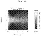
- FIG. 16 is a diagram showing a sound pressure distribution in an x-y plane reproduced by an area reproduction method according to the second modification of the present embodiment.
- the arrangement interval ⁇ x between the respective speakers 403 is 35 mm.
- a line orthogonal to the center of the speaker array SA in the x axis direction is the y axis and the distance y ref from the speaker array SA to the control line CL is 1 m.
- a reproduced sound emitted from the speaker array SA is heard only at the reproduction line BL on the control line CL to realize appropriate area reproduction, area reproduction performance backward of the control line CL is deteriorated.
- a reproduced sound emitted from the speaker array SA has a sound pressure in a non-reproduction area reduced not only on the control line CL but also backward of the control lure CL, so that deterioration of area reproduction performance backward of the control line CL can be improved.
- no side lobe is present in a sound pressure distribution in a spatial frequency domain, auditory easiness of hearing a reproduced sound can be improved.
- the spatial frequency processing portion 312 determines a spatial frequency kx corresponding to the angle ⁇ as a spatial frequency for use in the adjustment of reproduced sound.
- FIG. 17 is a schematic diagram for describing processing of determining a spatial frequency for use in adjustment of reproduced sound in the third modification of the present embodiment.
- the spatial frequency kx is represented by the above-described Formula (5)
- the angle ⁇ formed by a plane wave represented by the spatial frequency kx and the array line AL is represented by the above-described Formula (6).
- the spatial frequency processing portion 312 determines the spatial frequency kx corresponding to the angle ⁇ as a spatial frequency for use in the adjustment of reproduced sound. Then, the spatial frequency processing portion 312 sets a value of the sound pressure Pkx( ⁇ ) of the determined spatial frequency kx to be zero.
- FIG. 18 is a diagram showing one example of a sound pressure distribution on a control line in a frequency domain in the third modification of the present embodiment
- FIG. 19 is a diagram showing one example of a sound pressure distribution on a control line in a spatial frequency domain in the third modification of the present embodiment.
- a broken line denotes an area reproduction method according to a conventional technique
- a solid line denotes an area reproduction method according to the present embodiment.
- a sound pressure of the non-reproduction line DL on the control line CL is suppressed in a frequency domain.
- the sound pressure distribution shown in FIG. 18 is converted from a sound pressure distribution in a frequency domain into that in a spatial frequency domain, all the sound pressures of the non-reproduction line DL on the control line CL remain in a spatial frequency domain in the conventional technique as shown in FIG. 19 .
- a sound pressure of a part of the non-reproduction line DL on the control line CL is zero in a spatial frequency domain.
- the spatial frequency processing portion 312 multiplies a sound pressure distribution in a spatial frequency domain by a predetermined window function having a width of a predetermined threshold value of a spatial frequency.
- the window function can be, for example, a rectangular window or a Hanning window.
- FIG. 21 is a diagram showing one example of a window function for use in adjustment of reproduced sound in the fourth modification of the present embodiment.
- the window function shown in FIG. 21 is a Hanning window.
- the spatial frequency kx is represented by the above-described Formula (5).
- the spatial frequency processing portion 312 multiplies a sound pressure distribution in a spatial frequency domain by a Hanning window having a width of a predetermined threshold value of a spatial frequency.
- FIG. 22 is a diagram showing one example of a sound pressure distribution on a control line in a frequency domain in the fourth modification of the present embodiment
- FIG. 23 is a diagram showing one example of a sound pressure distribution on a control line in a spatial frequency domain in the fourth modification of the present embodiment.
- a broken line denotes an area reproduction method according to a conventional technique
- a solid line denotes an area reproduction method according to the present embodiment.
- a sound pressure of the non-reproduction line DL on the control line CL is suppressed in a frequency domain.
- the sound pressure distribution shown in FIG. 22 is converted from a sound pressure distribution in a frequency domain into that in a spatial frequency domain, all the sound pressures of the non-reproduction line DL on the control line CL remain in a spatial frequency domain in the conventional technique as shown in FIG. 23 .
- a sound pressure of the non-reproduction line DL cert the control line CL is zero in a spatial frequency domain.
- FIG. 24 is a diagram showing a sound pressure distribution in an x-y plane reproduced by the area reproduction method according to a conventional technique
- FIG. 25 is a diagram showing a sound pressure distribution in an x-y plane reproduced by an area reproduction method according to the fourth modification of the present embodiment.
- N 64
- N 64
- the arrangement interval ⁇ x between the respective speakers 403 is 35 mm.
- a reproduced sound emitted from the speaker array SA is heard only at the reproduction line BL on the control line CL to realize appropriate area reproduction, area reproduction performance backward of the control line CL is deteriorated.
- a reproduced sound emitted from the speaker array SA has a sound pressure in a non-reproduction area reduced not only on the control line CL but also backward of the control line CL, so that deterioration of area reproduction performance backward of the control line CL can be improved.
- no side lobe is present in a sound pressure distribution in a spatial frequency domain, auditory easiness of hearing a reproduced sound can be improved.
- control line includes one reproduction line BL
- present disclosure is not particularly limited thereto, and the control line CL may include the plurality of reproduction lines BL.
- the area reproduction system is allowed to output different reproduced sounds to the plurality of persons.
- FIG. 26 is a schematic diagram for describing a control line including a plurality of reproduction lines in a fifth modification of the present embodiment.
- the control line CL shown in FIG. 26 includes a first reproduction line BL 1 and a second reproduction line BL 2 .
- the touch panel 101 accepts user's input of reproduction conditions.
- the reproduction conditions include, for example, an arrangement interval ⁇ x between the respective speakers 403 , the number N of the speakers 403 provided in the speaker array SA, the distance y ref from the speaker array SA to the control line CL in the y axis direction, a width lb 1 of the first reproduction line BL 1 , a sound volume of a reproduced sound on the first reproduction line BL 1 , a width lb 2 of the second reproduction line BL 2 , and a sound volume of a reproduced sound on the second reproduction line BL 2 .
- the processing unit 30 obtains first sound source data to be reproduced on the first reproduction line BL 1 and second sound source data to be reproduced on the second reproduction line BL 2 from the data unit 20 .
- the drive signal D(x 0 , ⁇ ) is calculated by superimposition of a combination s i ( ⁇ )F i (x 0 , ⁇ ) of a control filter F i at each reproduction line position and the corresponding sound source s i .
- the filter generation portion 301 generates a drive signal D i for driving each speaker 403 by the sound source s i and the control filter F i of each speaker 403 and drives each speaker.
- the reproduction unit 40 outputs different reproduced sounds for the plurality of reproduction lines.
- each processing can be conducted by a processor or the like incorporated into a specific device (hereinafter, referred to as a local device) provided in the area reproduction system 1 .
- a local device a specific device
- each processing may be conducted by a cloud server or the like provided at a place different from a local device.
- the local device and the cloud server may have information in conjunction with each other to share each processing as is described in the present disclosure. Modes of the present disclosure will be described in the following.
- Each of the above-described devices is specifically a computer system configured with a microprocessor, a ROM, a RAM, a hard disk unit, a display unit, a keyboard, a mouse, and the like.
- a computer program is stored in the RAM or the hard disk unit.
- the computer program herein is formed by combining a plurality of instruction codes indicative of an instruction to the computer in order to realize predetermined function.
- a part or all of the above-described components forming each of the above-described devices may be configured with one system large scale integration (LSI).
- the system LSI is a super-multifunctional LSI manufactured with a plurality of components integrated on one chip.
- the system LSI is a computer system configured to include a microprocessor, a ROM, a RAM, and the like.
- a computer program is stored in the RAM. As a result of operation of the microprocessor according to the computer program, the system LSI realizes function thereof.
- a part or all of the components forming ach of the above-described devices may be configured with an IC card or a single module detachable from each device.
- the IC card or the module is a computer system configured with a microprocessor, a ROM, a RAM, and the like.
- the IC card or the module may include the above-described super-multifunctional LSI. As a result of operation of the microprocessor according to the computer program, the IC card or the module realizes function thereof.
- the present disclosure may relate to a processing method in the above-described area reproduction system 1 .
- the present disclosure may also relate to a computer program which realizes the processing method by a computer, or to a digital signal formed with a computer program.
- the present disclosure may relate to a computer program or a digital signal funned with a computer program and recorded in a computer readable recording medium such as a flexible disk, a hard disk, a CD-ROM, an MO, a DVD, a DVD-ROM, a DVD-RAM, a Blu-ray (registered trademark) Disc (BD) or a semiconductor memory.
- a computer readable recording medium such as a flexible disk, a hard disk, a CD-ROM, an MO, a DVD, a DVD-ROM, a DVD-RAM, a Blu-ray (registered trademark) Disc (BD) or a semiconductor memory.
- BD Blu-ray (registered trademark) Disc
- the present disclosure may relate to a digital signal recorded in these recording media.
- the present disclosure may also relate to a computer program or a digital signal formed with a computer program which is transmitted via a telecommunication line, a radio or cable communication line, network exemplified by the Internet, data broadcasting or the like.
- the present disclosure may also relate to a computer system including a microprocessor and a memory, the memory storing the above-described computer program and the microprocessor being operable according to the computer program.
- processing may be executed by other independent computer system by recording a program or a digital signal in a recording medium and transferring the same, or transferring a program or a digital signal via a network or the like.
- the area reproduction method, the computer readable recording medium which records an area reproduction program, and the area reproduction system enable improvement of deterioration of area reproduction performance backward of a control line provided near a speaker array and are useful as an area reproduction method of outputting reproduced sound from a speaker array including a plurality of speakers arranged to a predetermined area, a computer readable recording medium which records an area reproduction program, and an area reproduction system.
Landscapes
- Physics & Mathematics (AREA)
- Engineering & Computer Science (AREA)
- Acoustics & Sound (AREA)
- Signal Processing (AREA)
- Health & Medical Sciences (AREA)
- Otolaryngology (AREA)
- General Health & Medical Sciences (AREA)
- Circuit For Audible Band Transducer (AREA)
- Obtaining Desirable Characteristics In Audible-Bandwidth Transducers (AREA)
- Soundproofing, Sound Blocking, And Sound Damping (AREA)
Abstract
Description
kx=2πn/(NΔx) (1)
θ=180/πa sin(kx/(ω/c) (2)
P(x,y ref,ω)=∫−∞ ∞ D)(x 0,0,ω)G(x−x 0 ,y ref,ω)dx 0 (3)
{tilde over (P)}(k x ,y ref,ω)={tilde over (D)}(k x,ω)·{tilde over (G)}(k x ,y ref,ω) (4)
kx=2πn/(NΔx) (5)
θ=180/πa sin(kx/(ω/c)) (6)
D(x 0,0,ω)=S(ω)F(x 00,ω) (8)
Claims (12)
kx=2πn/(NΔx) (1),
θ=180/πa sin(kx/(ω/c)) (2),
Applications Claiming Priority (3)
| Application Number | Priority Date | Filing Date | Title |
|---|---|---|---|
| JP2017-254514 | 2017-12-28 | ||
| JPJP2017-254514 | 2017-12-28 | ||
| JP2017254514A JP6959134B2 (en) | 2017-12-28 | 2017-12-28 | Area playback method, area playback program and area playback system |
Publications (2)
| Publication Number | Publication Date |
|---|---|
| US20190208314A1 US20190208314A1 (en) | 2019-07-04 |
| US10945067B2 true US10945067B2 (en) | 2021-03-09 |
Family
ID=67058674
Family Applications (1)
| Application Number | Title | Priority Date | Filing Date |
|---|---|---|---|
| US16/217,996 Active 2039-04-20 US10945067B2 (en) | 2017-12-28 | 2018-12-12 | Area reproduction method, computer readable recording medium which records area reproduction program, and area reproduction system |
Country Status (3)
| Country | Link |
|---|---|
| US (1) | US10945067B2 (en) |
| JP (1) | JP6959134B2 (en) |
| CN (1) | CN109982197B (en) |
Families Citing this family (1)
| Publication number | Priority date | Publication date | Assignee | Title |
|---|---|---|---|---|
| US20220357834A1 (en) * | 2021-05-04 | 2022-11-10 | Harman International Industries, Incorporated | Techniques for positioning speakers within a venue |
Citations (9)
| Publication number | Priority date | Publication date | Assignee | Title |
|---|---|---|---|---|
| JP2007135199A (en) | 2005-10-12 | 2007-05-31 | Kanazawa Univ | Speaker array and microphone array |
| US20080089522A1 (en) * | 2004-07-20 | 2008-04-17 | Pioneer Corporation | Sound Reproducing Apparatus and Sound Reproducing System |
| US20120020480A1 (en) * | 2010-07-26 | 2012-01-26 | Qualcomm Incorporated | Systems, methods, and apparatus for enhanced acoustic imaging |
| JP2015231087A (en) | 2014-06-04 | 2015-12-21 | 国立研究開発法人情報通信研究機構 | Local acoustic reproduction device and program |
| US20160198282A1 (en) * | 2015-01-02 | 2016-07-07 | Qualcomm Incorporated | Method, system and article of manufacture for processing spatial audio |
| US20160255454A1 (en) * | 2013-10-07 | 2016-09-01 | Dolby Laboratories Licensing Corporation | Spatial Audio Processing System and Method |
| US20180279042A1 (en) * | 2014-10-10 | 2018-09-27 | Sony Corporation | Audio processing apparatus and method, and program |
| US20190014430A1 (en) * | 2017-07-07 | 2019-01-10 | Harman Becker Automotive Systems Gmbh | Loudspeaker-room system |
| US20190208315A1 (en) * | 2016-05-30 | 2019-07-04 | Sony Corporation | Locally silenced sound field forming apparatus and method, and program |
Family Cites Families (1)
| Publication number | Priority date | Publication date | Assignee | Title |
|---|---|---|---|---|
| JP5603307B2 (en) * | 2011-08-29 | 2014-10-08 | 日本電信電話株式会社 | Sound field recording / reproducing apparatus, method, and program |
-
2017
- 2017-12-28 JP JP2017254514A patent/JP6959134B2/en active Active
-
2018
- 2018-12-12 US US16/217,996 patent/US10945067B2/en active Active
- 2018-12-12 CN CN201811519039.9A patent/CN109982197B/en active Active
Patent Citations (9)
| Publication number | Priority date | Publication date | Assignee | Title |
|---|---|---|---|---|
| US20080089522A1 (en) * | 2004-07-20 | 2008-04-17 | Pioneer Corporation | Sound Reproducing Apparatus and Sound Reproducing System |
| JP2007135199A (en) | 2005-10-12 | 2007-05-31 | Kanazawa Univ | Speaker array and microphone array |
| US20120020480A1 (en) * | 2010-07-26 | 2012-01-26 | Qualcomm Incorporated | Systems, methods, and apparatus for enhanced acoustic imaging |
| US20160255454A1 (en) * | 2013-10-07 | 2016-09-01 | Dolby Laboratories Licensing Corporation | Spatial Audio Processing System and Method |
| JP2015231087A (en) | 2014-06-04 | 2015-12-21 | 国立研究開発法人情報通信研究機構 | Local acoustic reproduction device and program |
| US20180279042A1 (en) * | 2014-10-10 | 2018-09-27 | Sony Corporation | Audio processing apparatus and method, and program |
| US20160198282A1 (en) * | 2015-01-02 | 2016-07-07 | Qualcomm Incorporated | Method, system and article of manufacture for processing spatial audio |
| US20190208315A1 (en) * | 2016-05-30 | 2019-07-04 | Sony Corporation | Locally silenced sound field forming apparatus and method, and program |
| US20190014430A1 (en) * | 2017-07-07 | 2019-01-10 | Harman Becker Automotive Systems Gmbh | Loudspeaker-room system |
Also Published As
| Publication number | Publication date |
|---|---|
| CN109982197B (en) | 2022-02-08 |
| JP2019121872A (en) | 2019-07-22 |
| JP6959134B2 (en) | 2021-11-02 |
| US20190208314A1 (en) | 2019-07-04 |
| CN109982197A (en) | 2019-07-05 |
Similar Documents
| Publication | Publication Date | Title |
|---|---|---|
| US9402145B2 (en) | Wireless speaker system with distributed low (bass) frequency | |
| US11310617B2 (en) | Sound field forming apparatus and method | |
| US8831231B2 (en) | Audio signal processing device and audio signal processing method | |
| US9426598B2 (en) | Spatial calibration of surround sound systems including listener position estimation | |
| CN109804559B (en) | Gain control in spatial audio systems | |
| US10231072B2 (en) | Information processing to measure viewing position of user | |
| CN101640830B (en) | Transfer function estimating device, noise suppressing apparatus and transfer function estimating method | |
| US11284211B2 (en) | Determination of targeted spatial audio parameters and associated spatial audio playback | |
| JP2020500480A5 (en) | ||
| WO2017031972A1 (en) | Directivity recording method, apparatus and recording device | |
| CN106470379B (en) | Method and apparatus for processing audio signal based on speaker position information | |
| JP6718748B2 (en) | Area reproduction system and area reproduction method | |
| RU2018119087A (en) | DEVICE AND METHOD FOR FORMING A FILTERED AUDIO SIGNAL REALIZING AN ANGLE RENDERIZATION | |
| US9966058B2 (en) | Area-sound reproduction system and area-sound reproduction method | |
| US20150208169A1 (en) | Sound field correction apparatus, control method thereof, and computer-readable storage medium | |
| US9967660B2 (en) | Signal processing apparatus and method | |
| CN103517199A (en) | Apparatus and method for localizing sound image | |
| US10945067B2 (en) | Area reproduction method, computer readable recording medium which records area reproduction program, and area reproduction system | |
| US8422690B2 (en) | Audio reproduction apparatus and control method for the same | |
| CN113608167B (en) | Sound source positioning method, device and equipment | |
| JP7485982B2 (en) | Processing device, playback system, processing method, and processing program | |
| CN117751404A (en) | Region playback system and region playback method | |
| CN120581021A (en) | Audio zoom method, electronic device, storage medium and computer program product | |
| JP6027873B2 (en) | Impulse response generation apparatus, impulse response generation system, and impulse response generation program |
Legal Events
| Date | Code | Title | Description |
|---|---|---|---|
| FEPP | Fee payment procedure |
Free format text: ENTITY STATUS SET TO UNDISCOUNTED (ORIGINAL EVENT CODE: BIG.); ENTITY STATUS OF PATENT OWNER: LARGE ENTITY |
|
| AS | Assignment |
Owner name: PANASONIC INTELLECTUAL PROPERTY CORPORATION OF AME Free format text: ASSIGNMENT OF ASSIGNORS INTEREST;ASSIGNOR:SAKAGUCHI, ATSUSHI;REEL/FRAME:049002/0486 Effective date: 20181128 Owner name: PANASONIC INTELLECTUAL PROPERTY CORPORATION OF AMERICA, CALIFORNIA Free format text: ASSIGNMENT OF ASSIGNORS INTEREST;ASSIGNOR:SAKAGUCHI, ATSUSHI;REEL/FRAME:049002/0486 Effective date: 20181128 |
|
| STPP | Information on status: patent application and granting procedure in general |
Free format text: NOTICE OF ALLOWANCE MAILED -- APPLICATION RECEIVED IN OFFICE OF PUBLICATIONS |
|
| STCF | Information on status: patent grant |
Free format text: PATENTED CASE |
|
| MAFP | Maintenance fee payment |
Free format text: PAYMENT OF MAINTENANCE FEE, 4TH YEAR, LARGE ENTITY (ORIGINAL EVENT CODE: M1551); ENTITY STATUS OF PATENT OWNER: LARGE ENTITY Year of fee payment: 4 |