US10944830B2 - System and method for smart building control using directional occupancy sensors - Google Patents
System and method for smart building control using directional occupancy sensors Download PDFInfo
- Publication number
- US10944830B2 US10944830B2 US16/586,789 US201916586789A US10944830B2 US 10944830 B2 US10944830 B2 US 10944830B2 US 201916586789 A US201916586789 A US 201916586789A US 10944830 B2 US10944830 B2 US 10944830B2
- Authority
- US
- United States
- Prior art keywords
- control device
- master control
- physical space
- coordinate system
- measurement data
- Prior art date
- Legal status (The legal status is an assumption and is not a legal conclusion. Google has not performed a legal analysis and makes no representation as to the accuracy of the status listed.)
- Active - Reinstated
Links
Images


Classifications
-
- H—ELECTRICITY
- H04—ELECTRIC COMMUNICATION TECHNIQUE
- H04L—TRANSMISSION OF DIGITAL INFORMATION, e.g. TELEGRAPHIC COMMUNICATION
- H04L67/00—Network arrangements or protocols for supporting network services or applications
- H04L67/01—Protocols
- H04L67/12—Protocols specially adapted for proprietary or special-purpose networking environments, e.g. medical networks, sensor networks, networks in vehicles or remote metering networks
- H04L67/125—Protocols specially adapted for proprietary or special-purpose networking environments, e.g. medical networks, sensor networks, networks in vehicles or remote metering networks involving control of end-device applications over a network
-
- F—MECHANICAL ENGINEERING; LIGHTING; HEATING; WEAPONS; BLASTING
- F24—HEATING; RANGES; VENTILATING
- F24F—AIR-CONDITIONING; AIR-HUMIDIFICATION; VENTILATION; USE OF AIR CURRENTS FOR SCREENING
- F24F11/00—Control or safety arrangements
- F24F11/62—Control or safety arrangements characterised by the type of control or by internal processing, e.g. using fuzzy logic, adaptive control or estimation of values
- F24F11/63—Electronic processing
-
- G—PHYSICS
- G05—CONTROLLING; REGULATING
- G05B—CONTROL OR REGULATING SYSTEMS IN GENERAL; FUNCTIONAL ELEMENTS OF SUCH SYSTEMS; MONITORING OR TESTING ARRANGEMENTS FOR SUCH SYSTEMS OR ELEMENTS
- G05B15/00—Systems controlled by a computer
- G05B15/02—Systems controlled by a computer electric
-
- G—PHYSICS
- G05—CONTROLLING; REGULATING
- G05B—CONTROL OR REGULATING SYSTEMS IN GENERAL; FUNCTIONAL ELEMENTS OF SUCH SYSTEMS; MONITORING OR TESTING ARRANGEMENTS FOR SUCH SYSTEMS OR ELEMENTS
- G05B19/00—Program-control systems
- G05B19/02—Program-control systems electric
- G05B19/04—Program control other than numerical control, i.e. in sequence controllers or logic controllers
- G05B19/042—Program control other than numerical control, i.e. in sequence controllers or logic controllers using digital processors
-
- G—PHYSICS
- G08—SIGNALLING
- G08B—SIGNALLING SYSTEMS, e.g. PERSONAL CALLING SYSTEMS; ORDER TELEGRAPHS; ALARM SYSTEMS
- G08B21/00—Alarms responsive to a single specified undesired or abnormal condition and not otherwise provided for
- G08B21/18—Status alarms
- G08B21/22—Status alarms responsive to presence or absence of persons
-
- H—ELECTRICITY
- H04—ELECTRIC COMMUNICATION TECHNIQUE
- H04W—WIRELESS COMMUNICATION NETWORKS
- H04W4/00—Services specially adapted for wireless communication networks; Facilities therefor
- H04W4/02—Services making use of location information
- H04W4/029—Location-based management or tracking services
-
- F—MECHANICAL ENGINEERING; LIGHTING; HEATING; WEAPONS; BLASTING
- F24—HEATING; RANGES; VENTILATING
- F24F—AIR-CONDITIONING; AIR-HUMIDIFICATION; VENTILATION; USE OF AIR CURRENTS FOR SCREENING
- F24F2120/00—Control inputs relating to users or occupants
- F24F2120/10—Occupancy
-
- F—MECHANICAL ENGINEERING; LIGHTING; HEATING; WEAPONS; BLASTING
- F24—HEATING; RANGES; VENTILATING
- F24F—AIR-CONDITIONING; AIR-HUMIDIFICATION; VENTILATION; USE OF AIR CURRENTS FOR SCREENING
- F24F2120/00—Control inputs relating to users or occupants
- F24F2120/10—Occupancy
- F24F2120/12—Position of occupants
-
- G—PHYSICS
- G05—CONTROLLING; REGULATING
- G05B—CONTROL OR REGULATING SYSTEMS IN GENERAL; FUNCTIONAL ELEMENTS OF SUCH SYSTEMS; MONITORING OR TESTING ARRANGEMENTS FOR SUCH SYSTEMS OR ELEMENTS
- G05B2219/00—Program-control systems
- G05B2219/20—Pc systems
- G05B2219/26—Pc applications
- G05B2219/2614—HVAC, heating, ventillation, climate control
-
- G—PHYSICS
- G05—CONTROLLING; REGULATING
- G05B—CONTROL OR REGULATING SYSTEMS IN GENERAL; FUNCTIONAL ELEMENTS OF SUCH SYSTEMS; MONITORING OR TESTING ARRANGEMENTS FOR SUCH SYSTEMS OR ELEMENTS
- G05B2219/00—Program-control systems
- G05B2219/20—Pc systems
- G05B2219/26—Pc applications
- G05B2219/2642—Domotique, domestic, home control, automation, smart house
Definitions
- This disclosure relates generally to sensors and control systems for physical spaces. More specifically, this disclosure relates to a system and method for smart building control using directional occupancy sensing.
- Smart Buildings or buildings comprising physical spaces whose environmental control systems, such as lights, HVAC systems, and physical features (for example, ceiling fans or window shades) operate, at least in part, based on control inputs generated by the computerized application of predetermined rules to sensor data, offer tremendous promise in terms of improving how humans use physical spaces. For example, truly intelligent control of heating and lighting systems offers the possibility of significant improvements in energy efficiency beyond those attainable through passive structural improvements such as better insulation.
- a “smart building” is only as “smart” as the sensors are able to provide accurate and meaningful inputs to the algorithms for controlling parameters of the building's physical spaces.
- Embodiments according to this disclosure address technical problems associated with generating truly “smart” control inputs for environmental control systems.
- This disclosure provides a system and method for smart building control using directional occupancy sensing.
- a method of operating a master control device includes receiving, at an input-output interface of the master control device, a first plurality of electrical signals from presence sensors disposed in a physical space, the presence sensors associated with a coordinate system for the physical space, the master control device comprising a processor, a memory and the input-output interface.
- the method further includes generating, based on the first plurality of electrical signals from the presence sensors, background sensor values mapped to a coordinate system for the physical space, receiving, at the input-output interface of the master control device, a second plurality of electrical signals from the presence sensors, the second plurality of electrical signals received from at a first time and a second time, generating, based on the second plurality of electrical signals from the presence sensors, sensor values mapped to the coordinate system for the physical space at the first time and the second time, and subtracting the background sensor values from the sensor values mapped to the coordinate system at the first time and the second time to obtain measurement data.
- the method includes associating the measurement data with a moving object belonging to an object class, identifying, based on the measurement data, a first node corresponding to a determined location of the moving object within the coordinate system for the physical space, determining a track, based on the measurement data, the track comprising a link between a first node and another node in the coordinate system for the physical space and outputting, via the input-output interface of the master control device, a signal associated with the determined track.
- a master control device in a second embodiment, includes an input-output interface, a processor and a memory containing instructions, which when executed by the processor, cause the master control device to receive, at the input-output interface of the master control device, a first plurality of electrical signals from presence sensors disposed in a physical space, the presence sensors associated with a coordinate system for the physical space, the master control device comprising a processor, a memory and, the input-output interface.
- the instructions when executed by the processor, further cause the master control device to generate, based on the first plurality of electrical signals from the presence sensors, background sensor values mapped to a coordinate system for the physical space, receive, at the input-output interface of the master control device, a second plurality of electrical signals from the presence sensors, the second plurality of electrical signals received from at a first time and a second time, generate, based on the second plurality of electrical signals from the presence sensors, sensor values mapped to the coordinate system for the physical space at the first time and the second time, and subtract the background sensor values from the sensor values mapped to the coordinate system at the first time and the second time to obtain measurement data.
- the instructions when executed by the processor, still further cause the master control device to associate the measurement data with a moving object belonging to an object class, identify, based on the measurement data, a first node corresponding to a determined location of the moving object within the coordinate system for the physical space, determine a track, based on the measurement data, the track comprising a link between a first node and another node in the coordinate system for the physical space and output, via the input-output interface of the master control device, a signal associated with the determined track.
- a computer program product includes program code, which when executed by a processor, causes a master control device to receive, at the input-output interface of the master control device, a first plurality of electrical signals from presence sensors disposed in a physical space, the presence sensors associated with a coordinate system for the physical space, the master control device comprising a processor, a memory and the input-output interface.
- the program code when executed by the processor, causes the master control device to generate, based on the first plurality of electrical signals from the presence sensors, background sensor values mapped to a coordinate system for the physical space, receive, at the input-output interface of the master control device, a second plurality of electrical signals from the presence sensors, the second plurality of electrical signals received from at a first time and a second time, generate, based on the second plurality of electrical signals from the presence sensors, sensor values mapped to the coordinate system for the physical space at the first time and the second time, and subtract the background sensor values from the sensor values mapped to the coordinate system at the first time and the second time to obtain measurement data.
- the program code when executed by the processor, causes the master control device to associate the measurement data with a moving object belonging to an object class, identify, based on the measurement data, a first node corresponding to a determined location of the moving object within the coordinate system for the physical space, determine a track, based on the measurement data, the track comprising a link between a first node and another node in the coordinate system for the physical space and output, via the input-output interface of the master control device, a signal associated with the determined track.
- Couple and its derivatives refer to any direct or indirect communication between two or more elements, whether or not those elements are in physical contact with one another.
- transmit and “communicate,” as well as derivatives thereof, encompass both direct and indirect communication.
- the term “or” is inclusive, meaning and/or.
- controller means any device, system or part thereof that controls at least one operation. Such a controller may be implemented in hardware or a combination of hardware and software and/or firmware. The functionality associated with any particular controller may be centralized or distributed, whether locally or remotely.
- phrases “at least one of,” when used with a list of items, means that different combinations of one or more of the listed items may be used, and only one item in the list may be needed.
- “at least one of: A, B, and C” includes any of the following combinations: A, B, C, A and B, A and C, B and C, and A and B and C.
- various functions described below can be implemented or supported by one or more computer programs, each of which is formed from computer readable program code and embodied in a computer readable medium.
- application and “program” refer to one or more computer programs, software components, sets of instructions, procedures, functions, objects, classes, instances, related data, or a portion thereof adapted for implementation in a suitable computer readable program code.
- computer readable program code includes any type of computer code, including source code, object code, and executable code.
- computer readable medium includes any type of medium capable of being accessed by a computer, such as read only memory (ROM), random access memory (RAM), a hard disk drive, a compact disc (CD), a digital video disc (DVD), or any other type of memory.
- ROM read only memory
- RAM random access memory
- CD compact disc
- DVD digital video disc
- a “non-transitory” computer readable medium excludes wired, wireless, optical, or other communication links that transport transitory electrical or other signals.
- a non-transitory computer readable medium includes media where data can be permanently stored and media where data can be stored and later overwritten, such as a rewritable optical disc or an erasable memory device.
- FIG. 1 illustrates a network context for implementing a system and method for smart building control using directional occupancy sensing according to embodiments of this disclosure
- FIG. 2 illustrates a network and processing context for implementing a system and method for smart building control using directional occupancy sensing according to embodiments of this disclosure
- FIG. 3 illustrates aspects of a resistive mat presence sensor according to embodiments of this disclosure
- FIG. 4 illustrates aspects of a floor-mounted presence sensor according to embodiments of this disclosure
- FIG. 5 illustrates a master control device according to embodiments of this disclosure
- FIG. 6 illustrates operations of a method of determining tracks associated with moving occupants of a physical space according to embodiments of this disclosure
- FIG. 7 illustrates operations of a Kalman fitter according to embodiments of this disclosure.
- FIGS. 8A-8I illustrate aspects of a method for determining tracks from presence sensor data according to embodiments of this disclosure.
- FIGS. 1 through 8I discussed below, and the various embodiments used to describe the principles of this disclosure in this patent document are by way of illustration only and should not be construed in any way to limit the scope of the disclosure.
- Embodiments as disclosed herein relate to systems and methods for smart building control using directional occupancy sensing.
- the advent of the internet of things and development of physical spaces whose environmental control systems (for example, lights and HVAC systems) can be controlled using a broad spectrum of sensor data collected within the physical space presents many opportunities to make buildings “smarter,” in the sense of being attuned with, and responsive to, the needs and priorities of the buildings' human occupants.
- Effective integration of sensor technology and machine intelligence for processing and understanding the sensor data presents opportunities for meaningful improvements across a wide range of building functionalities.
- such integration can improve the efficiency of a building (for example, by focusing heating and cooling resources on the regions of a building that have the most people), improve a building's safety (for example, by performing footstep analysis to identify when an occupant of a building has fallen or stopped walking under circumstances suggesting concern, and extend the life cycle of a building (for example, by collecting data as to loading and use stress over a building's lifespan).
- Realizing the full potential of a “smart building” to learn about its occupants and control itself in response to, and in anticipation of, its occupants' needs is enhanced when data regarding a building's utilization is collected from sources that are a constant across the building's lifecycle, and which capture all, or almost all, of the relevant occupant usage data.
- the floor of a building is one example of a source of relevant occupant data for the entirety of the building's life. Walls can be knocked down and moved over the course of a building's lifetime, but the floor generally remains a structural constant. Similarly, barring unforeseeable changes in human locomotion, humans can be expected to generate measureable interactions with buildings through their footsteps on buildings' floors. Embodiments according to the present disclosure help realize the potential of the “smart building” by providing, amongst other things, control inputs for a building's environmental control systems using directional occupancy sensing based on occupants' interaction with building surfaces, including, without limitation, floors.
- FIG. 1 illustrates an example of a network context 100 for implementing a system and method for smart building control using directional occupancy sensing according to some embodiments of this disclosure.
- the embodiment of the network context 100 shown in FIG. 1 is for illustration only and other embodiments could be used without departing from the scope of the present disclosure.
- a network context 100 includes a master control device 105 (sometimes referred to as a gateway, one or more routers 110 a , 110 b , 110 c , 110 d , a client device 115 providing a user interface, a plurality of end devices 120 a - j in a physical space, and one or more appliances or features of a physical space receiving control signals (for example, HVAC system 125 ) from master control device 105 .
- a master control device 105 sometimes referred to as a gateway, one or more routers 110 a , 110 b , 110 c , 110 d , a client device 115 providing a user interface, a plurality of end devices 120 a - j in a physical space, and one or more appliances or features of a physical space receiving control signals (for example, HVAC system 125 ) from master control device 105 .
- a master control device 105 sometimes referred to as a gateway, one or more routers 110 a , 110 b ,
- master control device 105 is embodied on a low power processing platform, such as a development board running an ARM CORTEX′ processor.
- master control device 105 may be implemented on a larger computing platform, such as a notebook computer, a server computer, or a tablet comprising a memory, a processor, an input output interface, an analog to digital converter, and send and receive circuitry that includes a network interface and supports multiple communication protocols, including without limitation, Wi-Fi on the 900 MHz, 2.4 GHz and 5.0 GHz bands.
- master control device also supports communications using the ZIGBEE protocol and AES-128 encryption between devices in the network, including without limitation, routers 110 a - 110 d , end devices 120 a - j , client device 115 and HVAC system 125 .
- the memory of master control device 105 contains instructions, which when executed by the processor, cause the master control device to receive signals from end devices 120 a - j , determine tracks associated with moving occupants of a physical space based on the received signals, and output signals for controlling appliances and features of the physical space based on the determined tracks.
- master control device 105 is shown as embodied on a single, physical computing platform (such as a server or notebook), which is communicatively connected to other actors within network context 100 using various wireless communication protocols, numerous other embodiments are possible and within the intended scope of this disclosure.
- the operations carried out by master control device 105 in the embodiment shown in FIG. 1 can, in other embodiments, be performed on multiple machines, or by a different machine within network context 100 , such as client device 115 or one of end devices 120 a - j .
- master control device 105 may be embodied on one or more virtual machines.
- each router of routers 110 a - 110 d is a wireless router providing a Wi-Fi link between master control device 105 and each of end devices 120 a - 120 j .
- each of routers 110 a - 110 d support communications using, without limitation, the ZIGBEE, BLUETOOTH, BLUETOOTH Low Energy (BLE) and Wi-Fi communication protocols in the 900 MHz, 2.4 GHz and 5.0 GHz bands.
- routers 110 a - 110 d connect to one or more devices within network context 100 over a wired connection and communicate using wired communication protocols, such as Ethernet networking protocols.
- each of routers 110 a - 110 d may be connected to one another, as shown in FIG. 1 to form a mesh network.
- client device 115 is a smartphone providing a user interface for, without limitation, receiving information regarding determined tracks in the physical space, providing visualizations of determined tracks in the physical space, and controlling the transmission of control signals from master control device 105 to appliances and devices in the physical space (such as HVAC system 125 ) based on tracks determined by master control device 105 .
- each end device of end devices 120 a - 120 j comprises a floor mounted presence sensor capable of collecting floor contact data from within the physical space at predetermined intervals.
- the predetermined intervals at which floor contact data is collected corresponds to a scan rate that can be configured at master control device 105 or via a user interface of client device 115 .
- each end device of end devices 120 a - 120 j is embodied on a low-power general computing device such as a development board powered by an energy efficient processor, such as the INTEL ATOM′ processor.
- the presence sensor is a membrane switch, resistive sensor, piezoelectric sensor or capacitive sensor that, when contacted, produces or changes an electrical signal, from which a value along one or more coordinate axes assigned to the physical space can be mapped.
- the presence sensors of end devices 120 a - 120 j detect the presence or absence of contact with the floor.
- the presence sensors of end devices 120 a - 120 j produce an electric signal correlating to a pressure applied to the sensor.
- each of end devices 120 a - 120 j also include an analog-to-digital converter (“A/D”) to digitize the electrical signals.
- Further end devices 120 a - 120 j may include a memory, a processor and send and receive circuitry to provide the electrical signals from the presence sensors or digitizations thereof to routers 110 a - 110 d or master control device 105 .
- the send and receive circuitry of end devices 120 a - 120 j includes a network interface supporting one or more wired or wireless communication protocols, including without limitation, Ethernet, Zigbee, Wi-Fi, Bluetooth and Bluetooth Low Energy.
- the presence sensors of each of end devices 120 a - 120 j may, either by themselves, or under the control of master control device 105 form a self-configuring array of sensors, such as described in U.S. Provisional Patent Application No. 62/612,959, which is incorporated in by reference in its entirety.
- HVAC system 125 is a “smart” HVAC device, such as one of the component devices of the Carrier Comfort Network system.
- HVAC system 125 is a conventional HVAC device that has been retrofitted with a networked controller capable of receiving control inputs from master control device 105 .
- Skilled artisans will appreciate that HVAC system 125 is merely illustrative, and not limitative of the kinds of devices that can be controlled in response to inputs from master control device 105 .
- Other devices of a “smart building” whose operation can be controlled or adjusted based on signals from master control device 105 include, without limitation, IoT devices such as lights, window shades, room cleaning robots, windows, automatic doors, media systems, and security systems.
- FIG. 2 illustrates an example of a network context 200 for implementing a system and method for smart building control using directional occupancy sensing according to certain embodiments of this disclosure.
- the embodiment of the network context 200 shown in FIG. 2 is for illustration only and other embodiments could be used without departing from the scope of the present disclosure.
- a network context 200 includes one or more mat controllers 205 a , 205 b and 205 c , an API suite 210 , a trigger controller 220 , job workers 225 a - 225 d , a database 230 and a network 235 .
- each of mat controllers 205 a - 205 c is connected to a presence sensor in a physical space.
- each of mat controllers 205 is a mat controller, such as described in U.S. Provisional Patent Application No. 62/615,310, the contents of which are incorporated in their entirety herein.
- each of mat controllers 205 a - 205 c is an end device, such as one of end devices 120 a - 120 j described with reference to FIG. 2 herein.
- Mat controllers 205 a - 205 c generate floor contact data from presence sensors in a physical space and transmit the generated floor contact data to API suite 210 .
- data from mat controllers 205 a - 205 c is provided to API suite 210 as a continuous stream.
- mat controllers 205 a - 205 c provide the generated floor contact data to API suite 210 via the internet.
- mat controllers 205 a - 205 c employ other mechanisms, such as a bus or Ethernet connection to provide the generated floor data to API suite 210 are possible and within the intended scope of this disclosure.
- API suite 210 is embodied on a server computer connected via the internet to each of mat controllers 205 a - 205 c .
- API suite is embodied on a master control device, such as master control device 105 shown in FIG. 1 of this disclosure.
- API suite 210 comprises a Data Application Programming Interface (API) 215 a , an Events API 215 b and a Status API 215 c.
- API Data Application Programming Interface
- Data API 215 a is an API for receiving and recording mat data from each of mat controllers 205 a - 205 c .
- Mat events include, for example, raw, or minimally processed data from the mat controllers, such as the time and data a particular sensor was pressed and the duration of the period during which the sensor was pressed.
- Data API 215 a stores the received mat events in a database such as database 230 . In the non-limiting example shown in FIG.
- API suite 210 some or all of the mat events are received by API suite 210 as a stream of event data from mat controllers 205 a - 205 c .
- Data API 215 a operates in conjunction with trigger controller 220 to generate and pass along triggers breaking the stream of mat event data into discrete portions for further analysis.
- Events API 215 b receives data from mat controllers 205 a - 205 c and generates lower-level records of instantaneous contacts where a sensor on the mat is pressed and released.
- Status API 215 c receives data from each of mat controllers 205 a - 205 c and generates records of the operational health (for example, CPU and memory usage, processor temperature, whether all of the sensors from which a mat controller receives inputs is operational) of each of mat controllers 205 a - 205 c .
- status API 215 c stores the generated records of the mat controllers' operational health in database 230 .
- trigger controller 220 operates to orchestrate the processing and analysis of data received from mat controllers 205 a - 205 c .
- trigger controller 220 In addition to working with data API 215 a to define and set boundaries in the data stream from mat controllers 205 a - 205 c to break the received data stream into tractably sized and logically defined “chunks” for processing, trigger controller 220 also sends triggers to job workers 225 a - 225 c to perform processing and analysis tasks.
- the triggers comprise identifiers uniquely identifying each data processing job to be assigned to a job worker. In the non-limiting example shown in FIG.
- the identifiers comprise: 1.) a sensor identifier (or an identifier otherwise uniquely identifying the location of contact); 2.) a time boundary start identifying a time in which the mat went from an idle state (for example, an completely open circuit, or, in the case of certain resistive sensors, a baseline or quiescent current level) to an active state (a closed circuit, or a current greater than the baseline or quiescent level); and 3.) a time boundary end defining the time in which a mat returned to the idle state.
- an idle state for example, an completely open circuit, or, in the case of certain resistive sensors, a baseline or quiescent current level
- an active state a closed circuit, or a current greater than the baseline or quiescent level
- each of job workers 225 a - 225 c corresponds to an instance of a process performed at a computing platform, (for example, master control device 105 in FIG. 1 ) for determining tracks and performing an analysis of the tracks. Instances of processes may be added or subtracted depending on the number of events or possible events received by API suite 210 as part of the data stream from mat controllers 205 a - 205 c .
- job workers 225 a - 225 c perform an analysis of the data received from mat controllers 205 a - 205 c , the analysis having, in some embodiments, two stages.
- a first stage comprises deriving paths, or tracks from mat impression data.
- a second stage comprises characterizing those paths according to a certain criteria to, inter alia, provide metrics to an online dashboard (in some embodiments, provided by a UI on a client device, such as client device 115 in FIG. 1 ) and to generate control signals for devices (such as HVAC systems, lights, and internet of things “IoT” appliances) controlling operational parameters of a physical space where the mat impressions were recorded.
- an online dashboard in some embodiments, provided by a UI on a client device, such as client device 115 in FIG. 1
- control signals for devices such as HVAC systems, lights, and internet of things “IoT” appliances
- job workers 225 a - 225 c perform the constituent processes of a method for analyzing mat impressions to generate paths, or tracks.
- the method comprises the operations of obtaining impression data from database 230 , cleaning the obtained impression data and reconstructing paths using the cleaned data.
- cleaning the data includes removing extraneous sensor data, removing gaps between impressions caused by sensor noise, removing long impressions caused by objects placed on mats or by defective sensors, and sorting impressions by start time to produce sorted impressions.
- job workers 225 a - 225 c perform processes for reconstructing paths by implementing algorithms that first cluster impressions that overlap in time or are spatially adjacent. Next, the clustered data is searched, and pairs of impressions that start or end within a few milliseconds of one another are combined into footsteps, which are then linked together to form footsteps. Footsteps are further analyzed and linked to create paths.
- database 230 provides a repository of raw and processed mat impression data, as well as data relating to the health and status of each of mat controllers 205 a - 205 c .
- database 230 is embodied on a server machine communicatively connected to the computing platforms providing API suite 210 , trigger controller 220 , and upon which job workers 225 a - 225 c execute.
- database 230 is embodied on a cloud computing platform.
- network 235 comprises any network suitable for distributing mat data, determined paths and control signals based on determined paths, including, without limitation, the internet or a local network (for example, an intranet) of a smart building.
- FIG. 3 illustrates aspects of a resistive mat presence sensor 300 according to certain embodiments of the present disclosure.
- the embodiment of the resistive mat presence sensor 300 shown in FIG. 3 is for illustration only and other embodiments could be used without departing from the scope of the present disclosure.
- resistive mat presence sensor 300 may comprise a modified carpet or vinyl floor tile, and have dimensions of approximately 2′ ⁇ 2′.
- resistive mat presence sensor 300 is installed directly on a floor, with graphic layer 305 comprising the top-most layer relative to the floor.
- graphic layer 305 comprises a layer of artwork applied to presence sensor 300 prior to installation.
- Graphic layer 305 can variously be applied by screen printing or as a thermal film.
- a first structural layer 310 is disposed, or located, below graphic layer 305 and comprises one or more layers of durable material capable of flexing at least a few thousandths of an inch in response to footsteps or other sources of contact pressure.
- first structural layer 310 may be made of carpet, vinyl or laminate material.
- first conductive layer 315 is disposed, or located, below structural layer 310 .
- first conductive layer 315 includes conductive traces or wires oriented along a first axis of a coordinate system.
- the conductive traces or wires of first conductive layer 315 are, in some embodiments, copper or silver conductive ink wires screen printed onto either first structural layer 310 or resistive layer 320 .
- the conductive traces or wires of first conductive layer 315 are metal foil tape or conductive thread embedded in structural layer 310 .
- the wires or traces included in first conductive layer 315 are capable of being energized at low voltages on the order of 5 volts.
- connection points to a first sensor layer of another presence sensor or to mat controller are provided at the edge of each presence sensor 300 .
- a resistive layer 320 is disposed, or located, below conductive layer 315 .
- Resistive layer 320 comprises a thin layer of resistive material whose resistive properties change under pressure.
- resistive layer 320 may be formed using a carbon-impregnated polyethylene film.
- a second conductive layer 325 is disposed, or located, below resistive layer 320 .
- second conductive layer 325 is constructed similarly to first conductive layer 315 , except that the wires or conductive traces of second conductive layer 325 are oriented along a second axis, such that when presence sensor 300 is viewed from above, there are one or more points of intersection between the wires of first conductive layer 315 and second conductive layer 325 .
- pressure applied to presence sensor 300 completes an electrical circuit between a sensor box (for example, mat controller 225 a shown in FIG. 2 or master control device 105 shown in FIG. 1 ) and presence sensor, allowing a pressure-dependent current to flow through resistive layer 320 at a point of intersection between the wires of first conductive layer 315 and second conductive layer 325 .
- a second structural layer 330 resides beneath second conductive layer 325 .
- second structural layer 330 comprises a layer of rubber or a similar material to keep presence sensor 300 from sliding during installation and to provide a stable substrate to which an adhesive, such as glue backing layer 335 can be applied without interference to the wires of second conductive layer 325 .
- presence sensors according to this disclosure may omit certain layers, such as glue backing layer 335 and graphic layer 305 described in the non-limiting example shown in FIG. 3 .
- a glue backing layer 335 comprises the bottom-most layer of presence sensor 300 .
- glue backing layer 335 comprises a film of a floor tile glue, such as Roberts 6300 pressure sensitive carpet adhesive.
- FIG. 4 illustrates aspects of a floor mounted presence sensor according to various embodiments of this disclosure.
- the embodiment of the floor mounted presence sensor 400 shown in FIG. 4 is for illustration only and other embodiments could be used without departing from the scope of the present disclosure.
- a resistive mat presence sensor 400 has a plurality of conductive traces, including the traces numbered 405 a and 405 b , along a first axis, which, in this example, correspond to conductive traces in a first conductive layer (for example, conductive layer 315 in FIG. 3 ) of a resistive mat presence sensor. Further, resistive mat presence sensor 400 has a plurality of conductive traces, including the traces numbered 410 a and 410 b , along a second axis, which, in this example, correspond to conductive traces in a second conductive layer (for example, conductive layer 325 in FIG. 3 ) of a resistive mat presence sensor.
- Each of conductive traces connects separately to an end device.
- the end device is a mat controller 415 (for example, mat controller 205 a shown in FIG. 2 ).
- the end device is, for example, end device 120 a shown in FIG. 1 or master control device 105 shown in FIG. 1 are possible and within the scope of this disclosure.
- presence sensor 400 is shown as connecting directly with mat controller 415 . In other embodiments, presence sensor 400 connects to mat controller 415 through one or more additional presence sensors.
- the alignment and spacing of the conductive traces of the presence system correspond to the spatial increments of a coordinate system for a physical space in which the presence sensor is installed.
- the conductive wires are disposed within the conductive layers of the presence sensor at intervals of approximately three inches or less, as such as spacing provides a high resolution representation of the occupancy and traffic within the physical space.
- the resistive mat when pressure is applied (such as by a footstep) to the presence sensor, the resistive mat is compressed such that the electrical resistance between a trace in one layer of the resistive mat and a trace in another layer of the resistive mat is reduced, and a signal corresponding to the difference in electrical current from a baseline or quiescent value is observed (such as by an ammeter or voltmeter in mat controller 415 ) in the traces brought into proximity by the footstep.
- a signal corresponding to the difference in electrical current from a baseline or quiescent value is observed (such as by an ammeter or voltmeter in mat controller 415 ) in the traces brought into proximity by the footstep.
- an end device (for example, mat controller 415 or master control device 105 shown in FIG. 1 ) “scans” the voltages or currents observed at each of the terminals where traces of the presence sensors connect to the end device at predetermined intervals. Accordingly, a plurality of signals corresponding to the measured voltages or currents at each of the terminals at known times are recorded and passed to an input-output interface of the end device.
- the scan rate of approximately 100-200 Hertz (Hz), wherein the time between scans is on the order of 5-10 milliseconds (ms), is appropriate for capturing footstep data at a level of temporal granularity from which the directionality of footsteps can be determined. Faster and slower scan rates are possible and within the contemplated scope of this disclosure.
- traces 405 a - b and 410 a - b of presence sensor 400 are depicted as comprising part of a rectilinear coordinate system having uniformly sized spatial increments, the present disclosure is no so limited.
- Other embodiments are possible, such as embodiments in which one or more layers of traces are curved or fan shaped and define a radial coordinate system. Such embodiments may be advantageous for curving spaces, such as running tracks, velodromes or curved hallways.
- the coordinate system may have a finer spatial resolution in certain areas (such as the playing or performance area) and a coarser spatial resolution in other areas, such as hallways or concession stand areas.
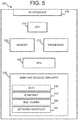
- FIG. 5 illustrates a master control device 500 according to certain embodiments of this disclosure.
- the embodiment of the master control device 500 shown in FIG. 5 is for illustration only and other embodiments could be used without departing from the scope of the present disclosure.
- master control device 500 is embodied on a standalone computing platform (for example, master control device 105 in FIG. 1 ) connected, via a network, to a series of end devices (for example, 120 a - 120 j in FIG. 1 , mat controller 205 a in FIG. 2 )
- master control device 105 connects directly to, and receives raw signals from, one or more presence sensors (for example, presence sensor 300 in FIG. 3 or presence sensor 400 in FIG. 4 ).
- master control device 500 includes one or more input/output interfaces (I/O) 505 .
- I/O interface 505 provides terminals that connect to each of the various conductive traces of the presence sensors deployed in a physical space.
- I/O interface 505 electrifies certain traces (for example, the traces contained in a first conductive layer, such as conductive layer 315 in FIG. 3 ) and provides a ground or reference value for certain other traces (for example, the traces contained in a second conductive layer, such as conductive layer 325 in FIG. 3 ).
- I/O interface 505 also measures current flows or voltage drops associated with occupant presence events, such as a person's foot squashing a membrane switch to complete a circuit, or compressing a resistive mat, causing a change in a current flow across certain traces.
- I/O interface 505 amplifies or performs an analog cleanup (such as high or low pass filtering) of the raw signals from the presence sensors in the physical space in preparation for further processing.
- master control device 500 includes an analog-to-digital converter (“ADC”) 510 .
- ADC analog-to-digital converter
- ADC 510 digitizes the analog signals.
- ADC 510 augments the converted signal with metadata identifying, for example, the trace(s) from which the converted signal was received, and time data associated with the signal. In this way, the various signals from presence sensors can be associated with touch events occurring in a coordinate system for the physical space at defined times. While in the non-limiting example shown in FIG.
- ADC 510 is shown as a separate component of master control device 500 , the present disclosure is not so limiting, and embodiments wherein ADC 510 is part of, for example, I/O interface 505 or processor 515 are contemplated as being within the scope of this disclosure.
- master control device 500 further comprises a processor 515 .
- processor 515 is a low-energy microcontroller, such as the ATMEGA328P by Atmel Corporation. According to other embodiments, processor 515 is the processor provided in other processing platforms, such as the processors provided by tablets, notebook or server computers.
- master control device 500 includes a memory 520 .
- memory 520 is a non-transitory memory containing program code to implement, for example, APIs 525 , networking functionality and the algorithms for generating and analyzing tracks described herein.
- master control device 500 includes one or more Application Programming Interfaces (APIs) 525 .
- APIs 525 include APIs for determining and assigning break points in one or more streams of presence sensor data and defining data sets for further processing.
- APIs 525 include APIs for interfacing with a job scheduler (for example, trigger controller 220 in FIG. 2 ) for assigning batches of data to processes for analysis and determination of tracks.
- APIs 525 include APIs for interfacing with one or more reporting or control applications provided on a client device (for example, client device 115 in FIG. 1 ).
- APIs 525 include APIs for storing and retrieving presence sensor data in one or more remote data stores (for example, database 230 in FIG. 2 ).
- master control device 500 includes send and receive circuitry 530 , which supports communication between master control device 500 and other devices in a network context in which smart building control using directional occupancy sensing is being implemented according to embodiments of this disclosure.
- send and receive circuitry 530 includes circuitry 535 for sending and receiving data using Wi-Fi, including, without limitation at 900 MHz, 2.8 GHz and 5.0 GHz.
- send and receive circuitry 530 includes circuitry, such as Ethernet circuitry 540 for sending and receiving data (for example, presence sensor data) over a wired connection.
- send and receive circuitry 530 further comprises circuitry for sending and receiving data using other wired or wireless communication protocols, such as Bluetooth Low Energy or Zigbee circuitry.
- send and receive circuitry 530 includes a network interface 550 , which operates to interconnect master control device 500 with one or more networks.
- Network interface 550 may, depending on embodiments, have a network address expressed as a node ID, a port number or an IP address.
- network interface 550 is implemented as hardware, such as by a network interface card (NIC).
- NIC network interface card
- network interface 550 may be implemented as software, such as by an instance of the java.net.NetworkInterface class.
- network interface 550 supports communications over multiple protocols, such as TCP/IP as well as wireless protocols, such as 3G or Bluetooth.
- FIG. 6 illustrates operations of a method 600 for determining tracks associated with moving occupants of a physical space according to various embodiments of this disclosure. While the flow chart depicts a series of sequential steps, unless explicitly stated, no inference should be drawn from that sequence regarding specific order of performance, performance of steps or portions thereof serially rather than concurrently or in an overlapping manner, or performance of the steps depicted exclusively without the occurrence of intervening or intermediate steps.
- the operations of method 600 are carried out by “job workers” or processes orchestrated by a gateway or master control device (for example, master control device 500 in FIG. 5 ).
- a gateway or master control device for example, master control device 500 in FIG. 5 .
- Other embodiments are possible, including embodiments in which the described operations are performed across a variety of machines, including physical and virtual computing platforms.
- method 600 includes operation 605 , wherein a first plurality of electrical signals is received by an input/output interface (for example, I/O interface 505 in FIG. 5 ) of a master control device from presence sensors (for example, a self-configuring array of presence sensors, such as certain embodiments of end devices 120 a - 120 j in FIG. 1 ) in a physical space under analysis.
- the first plurality of electrical signals is received at multiple points in time, based on several scans of the presence sensors in the physical space by the master control device.
- the received analog electrical signals may be digitized (for example, by ADC 510 in FIG. 5 ) and stored in a memory (for example, memory 520 in FIG. 5 or database 230 in FIG. 2 ).
- method 600 includes operation 610 , wherein the master control device generates background sensor values.
- the master control device maps the presence sensor signals received at operation 605 to sensor values mapped to a coordinate system for the physical space (for example, the grid type coordinate system 800 in FIG. 8 ).
- each trace of the presence sensor corresponds to a value on a coordinate axis for the physical space
- each intersection of traces corresponds to a “pixel” having a location in the physical space.
- the mapping of coordinate values comprises pairing the traces from which each signal of the first plurality of electrical signals was received to identify a “pixel,” or location in the physical space associated with the received presence sensor signals.
- background sensor values mapped to the coordinate system for the physical space are generated in one of at least two ways.
- the first plurality of electrical signals is received over a time known to be a period of low activity in the physical space (for example, in cases where the physical space is a store, when the store is closed).
- the sensor values collected during periods of inactivity may are assumed to be generated by furniture and other static actors in the space and comprise the background sensor values for the physical space.
- the master control device categorizes the sensor values as “fast” and “slow” and maintains a running estimate of “foreground” and “background” sensor values by fitting two normal distributions to each pixel with “fast” and “slow” responses.
- method 600 includes operation 615 , wherein the master control device receives a second plurality of electrical signals comprising presence sensor signals at multiple points in time, such as presence sensor signals received from two or more “scans” of the presence sensors by the master control device.
- the second plurality of electrical signals include an analog component that may be digitized (for example, by ADC 510 in FIG. 5 ) and stored in a memory (for example, memory 520 in FIG. 5 or database 230 in FIG. 2 ).
- method 600 includes operation 620 , wherein the master control device generates, based on the second plurality of electrical signals from the presence sensors, sensor values mapped to “pixels” within the coordinate system and points in time.
- a first sensor value generated in operation 620 may be expressed as a string of the general form: (053104061), wherein the first four digits “0531” correspond to a time value, the fifth and sixth digits (“04”) correspond to an angle in a radial coordinate system, the seventh and eighth digits (“06”) correspond to a distance in the radial coordinate system, and the last digit (“1”) corresponds to the measured state (for example, “on” or “off”) of the presence sensor.
- Skilled artisans will appreciate that the foregoing examples of sensor values are purely illustrative, and other representations of location, time and presence sensor values are possible and within the intended scope of this disclosure.
- method 600 is shown as including operation 625 , wherein background sensor values (for example, the sensor values generated at operation 610 in FIG. 6 ) are subtracted from the sensor values generated at operation 620 to produce measurement data associated with the activities of the mobile occupants in the physical space.
- background sensor values for example, the sensor values generated at operation 610 in FIG. 6
- the master control device can obtain an unimpeded view of activity within the physical space.
- method 600 includes operation 630 , wherein the master control device associates measurement data (for example, the measurement data generated in operation 625 ) with one or more moving objects belonging to an object class.
- measurement data for example, the measurement data generated in operation 625
- the density of traces (and spatial resolution) of the presence sensor is such that the sensor value at each pixel in the coordinate system can be examined in the context of neighboring sensors and time windows to classify the activity associated with the measurement data.
- the master control device implements a classification algorithm that operates on the assumptions about the moving actors in the physical space. For example, in some embodiments, it is an operational assumption that footsteps form, persist on timescales on the order of one or two seconds, and then disappear. As a further example, it is an operational assumptions that wheels (such as from wheelchairs, bicycles, carts and the like) roll across a surface in a continuous motion.
- the measurement data can be associated with moving objects belonging to predefined object classes.
- a tracker corresponding to the location of the moving object in time is assigned to the moving object based on the measurement data. Further, according to some embodiments, trackers move from along tracks, which may be determined paths in a network of nodes in the coordinate system for the physical space.
- presence sensors are deployed in a physical space at a density that supports a spatial resolution of approximately 3 inches, and the master control device is configured to scan the presence sensors at intervals of approximately 5 ms (corresponding to a scan rate of 200 Hz).
- measurement data for a first point in the coordinate system correlating to a high applied pressure for example, 200 psi
- the measurement data shows a decrease in applied pressure at the first point, and a moderate increase in pressure (for example, 20 psi) at one or more points adjacent to the first point.
- the master control device associates the generated measurement data with the footstep of a person wearing high heeled shoes and moving generally along a line passing through the first point and the one or more adjacent points.
- t 0 measurement data corresponding to a uniform applied pressure at five evenly spaced points in the coordinate system is generated. Over the course of the next five seconds, the measurement data shows five similarly spaced points of contact having approximately the same applied pressure values. Applying predetermined rules, the master control device associates the generated measurement data with the motion of an office chair on five caster wheels moving across the floor.
- method 600 includes operation 635 , wherein the master control device identifies, based on the measurement data, a first node corresponding to a determined location of the moving object (for example, the moving object associated with an object class described with reference to operation 630 ).
- a node corresponds to a single value within the coordinate system corresponding to the location, at a given time, of a moving object in the physical space.
- certain moving objects of interest in the physical space for example, humans wearing shoes
- nodes, or single points corresponding to the location of the actor provide an analytical convenience and useful representation of the location associated with multiple pieces of measurement data.
- a first node corresponding to a determined location of the moving object may be determined by applying a na ⁇ ve clustering algorithm that clusters measurement data within a specified radius of a tracker and determines a node (such as by calculating a centroid associated with the measurement data) based on the measurement data within the cluster.
- the specified radius is on the order of three feet.
- the first node is determined using another clustering algorithm, such as one of the clustering algorithms provided in the NumPy library.
- clustering algorithms suitable for generating the first node include, without limitation, K-Means clustering, Affinity Propagation clustering, and the sklearn.cluster method.
- nodes may be assigned retroactively, based on the application of predetermined rules. For example, in cases where measurement data belonging to a first instance of a moving object class (for example, a footstep associated with a person wearing high-heeled shoes) is observed, a node may be assigned to the nearest door, based on a predetermined rule requiring that occupants of the physical space enter and exit via the doors.
- a moving object class for example, a footstep associated with a person wearing high-heeled shoes
- method 600 includes operation 640 , wherein the master control device generates, based on the measurement data at multiple time points, a track linking the first node (for example, the node determined during operation 635 ) with another node in the coordinate system for the physical space.
- the generation of nodes is based on the application of a recursive algorithm to the measurement data, to smooth out the paths between nodes and to mitigate the effects of noise in the data.
- recursive algorithms for generating nodes may incorporate a predict/update step where an occupant's predicted location is used to update which footsteps are assigned to a tracker associated with the occupant.
- nodes are generated by implementing a recursive estimation algorithm, such as a Kalman fitter (for example, the Kalman fitter described in FIG. 7 ).
- a Kalman fitter for example, the Kalman fitter described in FIG. 7 .
- the generated nodes are connected together in a network to form tracks associated with the path of moving objects and occupants of the physical space.
- the nodes are connected using a network algorithm (For example, the NetworkX package for Python) that generates a graph of nodes and edges connecting the nodes.
- a network algorithm For example, the NetworkX package for Python
- the network links or “edges” are pruned according to distance and time-based penalty terms to find unique tracks through the coordinate system associated with the physical space.
- track overlap can be represented by increasing the weight of the edges and by allowing tracks to merge and split.
- method 600 is shown as including operation 645 , wherein a signal associated with the determined track is outputted.
- the output signal may be a running tally of the number of determined tracks in the room, which corresponds generally to the number of occupants in the room.
- the output signal may comprise a plot of the determined tracks at a given time point, or a map of “hot spots” of high human traffic in the physical space.
- the signal outputted at operation 645 is a control signal for an electrical appliance or other feature of the physical space (e.g., a window shade, door or lock) whose operation can be controlled or based at least in part on a signal from a master control device according to various embodiments of this disclosure.
- the determined tracks may show the occupants of a physical space moving towards a particular region of the space (for example, near a television or screen showing a news item or sporting event of broad interest), and the master control device may output a control signal to the HVAC system (for example, HVAC system 125 shown in FIGURE) increasing the power of the HVAC system in a particular region of the room.
- the HVAC system for example, HVAC system 125 shown in FIGURE
- FIG. 7 illustrates operations of a Kalman fitter 700 according to certain embodiments of this disclosure. While the flow chart depicts a series of sequential steps, unless explicitly stated, no inference should be drawn from that sequence regarding specific order of performance, performance of steps or portions thereof serially rather than concurrently or in an overlapping manner, or performance of the steps depicted exclusively without the occurrence of intervening or intermediate steps.
- the Kalman fitter 700 described with reference to the non-limiting example shown in FIG. 7 is one example of an algorithm for generating nodes encompassed by this disclosure. In some embodiments, Kalman fitter 700 provides the benefit of managing noise from the sensors and determining less “jittery” tracks associated with moving objects within the physical space.
- Kalman fitter 700 is a recursive estimation algorithm and includes operation 705 , wherein a master control device (for example, master control device 105 in FIG. 1 ) assigns a tracker to a moving object belonging to a determined object class.
- a tracker corresponds to a point coordinate for a person, object or other moving entity of interest that contacts presence sensors at multiple points (for example, a mail cart on casters) or discontinuous intervals (for example, a walking human).
- Kalman fitter 700 includes operation 710 , wherein the master control device receives measurement data (for example, a set of clustered impression data points corresponding to one or more possible directions of motion for the moving object that is being tracked) corresponding to the state of the moving object at a first time, T 1 .
- Information regarding the state of the moving object at first time T 1 can include, without limitation, information as to the moving object's location, apparent direction of motion and apparent rate of motion.
- the information as to the moving object's location, apparent direction and rate of motion is determined based on footstep and stride analysis of presence sensor data assumed by the master control device to be footsteps.
- the measurement data corresponding to the state of the moving object at a time T 1 comprises only the moving object's location within the physical space.
- Kalman fitter 700 is a recursive estimation process, and operation 710 marks the start of a loop repeated for a period relevant to the operation of one or more environmental control systems of a physical space, or of other analytical interest (for example, the interval beginning when a tracker associated with a human being in the physical space is assigned, and ending when the human being is determined to have departed the physical space, such as by leaving the room).
- Kalman fitter 700 includes operation 715 , wherein the master control unit predicts, based on the measurement data corresponding to the state of the moving object at time T 1 , measurement data corresponding to the state of the moving object at a subsequent time, T 2 .
- the master control device may also determine an uncertainty value associated with the predicted measurement data at time T 2 .
- the uncertainty associated with the predicted measurement data corresponding to the state of the moving object at time T 2 may be expressed as, or determined from an uncertainty matrix associated with the measurement data.
- Kalman fitter 700 includes operation 720 , wherein the master control device receives measurement data corresponding to the state of the moving object at time T 2 .
- the values of measurement data received as part of operation 720 correspond to fields of measurement data received at operation 710 and predicted at operation 715 .
- Kalman fitter 700 further includes operation 725 , wherein the master control device updates the measurement data corresponding to the moving object at time T 2 based on the predicted measurement data corresponding to the state of the moving object at time T 2 .
- the updating of the recorded measurement data at time T 2 based on the predicted measurement data for time T 2 comprises taking a weighted average of the values of the recorded measurement data with the predicted values of the measurement data at time T 2 .
- the relative weights of the recorded and predicted values of the measurement data is determined based on the uncertainty value or uncertainty matrix associated with the predicted value at operation 715 .
- Kalman fitter 700 implements a recursive estimation method. According to such embodiments, after operation 725 , the method returns to operation 710 , using the updated values of the measurement data corresponding to the moving object at time T 2 , as an initial value for a subsequent prediction.
- FIGS. 8A-8I illustrate aspects of a method for determining tracks based on presence data according to certain embodiments of this disclosure.
- FIGS. 8A-8I illustrate activity in a coordinate system corresponding to a person entering a room and walking through the room, and how certain embodiments according to this disclosure determine a track corresponding to the person's motion into and through the room.
- FIGS. 8A-8I depict activity in a coordinate system for the physical space (e.g., a room) beginning with an “empty” (noise and background presence sensor values) coordinate system for the physical space, followed by the detection of presence sensor data an initial time, assignment of a tracker, detection of additional presence sensor data at a subsequent time, and the determination of tracks connecting nodes within the coordinate system for the physical space.
- the physical space e.g., a room
- FIG. 8A depicts a coordinate system 800 for a physical space at an initial time.
- the embodiment of the coordinate system 800 shown in FIG. 8A is for illustration only and other embodiments could be used without departing from the scope of the present disclosure.
- the axes of coordinate system 800 are based on the direction of the traces in two separate layers (for example, layers 315 and 325 shown in FIG. 3 ) of conductive mat presence sensors installed in the physical space.
- coordinate system 800 provides a representation of the physical space after the “background” presence sensor values caused by furniture, noise and other factors have been subtracted out (for example, by performing operation 625 in FIG. 6 ).
- FIG. 8B depicts activity in the coordinate system 800 for the physical space at a time subsequent to the time shown in FIG. 8A .
- the embodiment of the coordinate system 800 shown in FIG. 8B is for illustration only and other embodiments could be used without departing from the scope of the present disclosure.
- Measurement data 805 corresponding to electrical signals generated at one or more presence sensors in the physical space has been mapped to a location in the coordinate system 800 for the physical space.
- the measurement data 805 is represented as a shaded region, indicating that electrical signals were generated by presence sensors in the shaded region.
- Other representations of measurement data are possible, and include, without limitation, dots corresponding to overlap points between traces in of layers of a resistive mat through which a current or potential change was detected.
- FIG. 8C depicts activity in the coordinate system 800 for the physical space subsequent to mapping measurement data 805 to a location in coordinate system 800 .
- the embodiment of the coordinate system 800 shown in FIG. 8C is for illustration only and other embodiments could be used without departing from the scope of the present disclosure.
- measurement data 805 has been associated with a moving object belonging to an object class (in this particular example, a walking human), and a tracker 810 has been assigned to the moving object.
- tracker 810 corresponds to a single point in the coordinate system (the single point is shown as a black dot within a dotted line included to help distinguish the tracker from other entities in coordinate system 800 ).
- FIG. 8D depicts activity in the coordinate system 800 for the physical space subsequent to assigning a tracker to the human moving in the physical space.
- the embodiment of the coordinate system 800 shown in FIG. 8D is for illustration only and other embodiments could be used without departing from the scope of the present disclosure.
- the initial position of the tracker in the coordinate system 800 has been designated as a first node 815 and the start of a new track for the tracker assigned to the human moving in the physical space.
- a master control device for example, master control device 105 in FIG. 1
- a Kalman fitter for example, Kalman fitter 700 described with reference to FIG. 7
- the predicted position of the tracker at subsequent time T 2 is shown by unshaded circle 820 .
- the recursion rate of a Kalman fitter is the same as the rate at which a master control device scans for electrical signals from presence sensors. In other embodiments, for example, where moving objects' interactions (such as footsteps) occur over intervals that are significantly longer than the scan rate, the recursion rate of a Kalman fitter may be lower than the scan rate for the presence sensors.
- FIG. 8E depicts activity in the coordinate system 800 for the physical space at time T 2 .
- additional measurement data 825 associated with the tracked human has been received and mapped to a location within the coordinate system 800 for the physical space.
- the embodiment of the coordinate system 800 shown in FIG. 8E is for illustration only and other embodiments could be used without departing from the scope of the present disclosure.
- FIG. 8F depicts activity in the coordinate system 800 for the physical space at a time subsequent to time T 2 .
- the embodiment of the coordinate system 800 shown in FIG. 8F is for illustration only and other embodiments could be used without departing from the scope of the present disclosure.
- FIG. 8F depicts that tracker 810 has moved to a second node corresponding to a position for the tracked human determined based on the predicted position 820 of the tracked human at time T 2 and the measurement data 825 received at time T 2 .
- the location of the second node to which tracker 810 has been moved is determined based on a weighted average of the predicted position 820 and measurement data 825 , wherein the weighting is based, at least in part, on an uncertainty value determined for predicted position 820 .
- the master control device performs a determination as to whether the newly determined position of tracker 810 satisfies one or more predetermined conditions, such as expected changes time or distance between nodes or conditions indicating possible pileups of nodes or tracks. If the predetermined conditions are determined to have been satisfied, the master control device creates track 830 connecting the first and second nodes.
- predetermined conditions such as expected changes time or distance between nodes or conditions indicating possible pileups of nodes or tracks.
- FIG. 8G depicts activity in the coordinate system 800 for the physical space at the start of a new recursion of the Kalman fitter, in which the predicted location 835 of the moving human in the physical space at a new subsequent time T 3 is determined based on the position of tracker 810 at time T 2 .
- the embodiment of the coordinate system 800 shown in FIG. 8G is for illustration only and other embodiments could be used without departing from the scope of the present disclosure.
- FIG. 8H depicts activity in the coordinate system 800 for the physical space at time T 3 .
- the embodiment of the coordinate system 800 shown in FIG. 8H is for illustration only and other embodiments could be used without departing from the scope of the present disclosure.
- the master control device receives additional measurement data 840 from presence sensors and maps the additional measurement data 840 to a location within the coordinate system 800 for the physical space. Additionally, the master control device applies a clustering algorithm (for example, one of the clustering algorithms described with reference to operation 635 in FIG. 6 ) that clusters measurement data 825 and 840 based on their physical and temporal proximity of the measurement data and assigns a point coordinate for the clustered measurement data 845 . For the purposes of implementing the Kalman fitter, the point coordinate for the clustered measurement data 845 is the measurement data for time T 3 .
- a clustering algorithm for example, one of the clustering algorithms described with reference to operation 635 in FIG. 6
- the point coordinate for the clustered measurement data 845 is the measurement data for time T 3 .
- FIG. 8I depicts activity in the coordinate system 800 for the physical space at a time subsequent to time T 3 .
- the embodiment of the coordinate system 800 shown in FIG. 8I is for illustration only and other embodiments could be used without departing from the scope of the present disclosure.
- the tracker moves to a new node determined based on a weighted average of the predicted location of the moving human at time T 3 and the clustered measurement data. Further, the master control device performs a determination as to whether the newly determined position of tracker 810 satisfies one or more predetermined conditions, such as expected changes time or distance between nodes or conditions indicating possible pileups of nodes or tracks. If the predetermined conditions are determined to have been satisfied, the master control device creates track 850 connecting the first and second nodes.
- predetermined conditions such as expected changes time or distance between nodes or conditions indicating possible pileups of nodes or tracks.
- the method described with reference to FIGS. 8A-8I recurs until a terminal condition, such as a determination that the tracked human has left the physical space, is satisfied.
- the master control device outputs the determined tracks, data derived from the determined tracks, or control signals (such as turning a light on or off) based on the determined tracks.
Landscapes
- Engineering & Computer Science (AREA)
- Signal Processing (AREA)
- Physics & Mathematics (AREA)
- General Physics & Mathematics (AREA)
- General Engineering & Computer Science (AREA)
- Computer Networks & Wireless Communication (AREA)
- Automation & Control Theory (AREA)
- Chemical & Material Sciences (AREA)
- Mathematical Physics (AREA)
- Combustion & Propulsion (AREA)
- Mechanical Engineering (AREA)
- Fuzzy Systems (AREA)
- Health & Medical Sciences (AREA)
- Computing Systems (AREA)
- General Health & Medical Sciences (AREA)
- Medical Informatics (AREA)
- Business, Economics & Management (AREA)
- Emergency Management (AREA)
- Selective Calling Equipment (AREA)
Abstract
Description
Claims (6)
Priority Applications (1)
| Application Number | Priority Date | Filing Date | Title |
|---|---|---|---|
| US16/586,789 US10944830B2 (en) | 2018-01-02 | 2019-09-27 | System and method for smart building control using directional occupancy sensors |
Applications Claiming Priority (6)
| Application Number | Priority Date | Filing Date | Title |
|---|---|---|---|
| US201862612959P | 2018-01-02 | 2018-01-02 | |
| US201862615310P | 2018-01-09 | 2018-01-09 | |
| US201862644130P | 2018-03-16 | 2018-03-16 | |
| US201862646537P | 2018-03-22 | 2018-03-22 | |
| US16/234,498 US10469590B2 (en) | 2018-01-02 | 2018-12-27 | System and method for smart building control using directional occupancy sensors |
| US16/586,789 US10944830B2 (en) | 2018-01-02 | 2019-09-27 | System and method for smart building control using directional occupancy sensors |
Related Parent Applications (1)
| Application Number | Title | Priority Date | Filing Date |
|---|---|---|---|
| US16/234,498 Continuation US10469590B2 (en) | 2018-01-02 | 2018-12-27 | System and method for smart building control using directional occupancy sensors |
Publications (2)
| Publication Number | Publication Date |
|---|---|
| US20200028915A1 US20200028915A1 (en) | 2020-01-23 |
| US10944830B2 true US10944830B2 (en) | 2021-03-09 |
Family
ID=67058582
Family Applications (3)
| Application Number | Title | Priority Date | Filing Date |
|---|---|---|---|
| US16/234,232 Abandoned US20190208018A1 (en) | 2018-01-02 | 2018-12-27 | System and method for smart building control using multidimensional presence sensor arrays |
| US16/234,498 Active US10469590B2 (en) | 2018-01-02 | 2018-12-27 | System and method for smart building control using directional occupancy sensors |
| US16/586,789 Active - Reinstated US10944830B2 (en) | 2018-01-02 | 2019-09-27 | System and method for smart building control using directional occupancy sensors |
Family Applications Before (2)
| Application Number | Title | Priority Date | Filing Date |
|---|---|---|---|
| US16/234,232 Abandoned US20190208018A1 (en) | 2018-01-02 | 2018-12-27 | System and method for smart building control using multidimensional presence sensor arrays |
| US16/234,498 Active US10469590B2 (en) | 2018-01-02 | 2018-12-27 | System and method for smart building control using directional occupancy sensors |
Country Status (1)
| Country | Link |
|---|---|
| US (3) | US20190208018A1 (en) |
Cited By (4)
| Publication number | Priority date | Publication date | Assignee | Title |
|---|---|---|---|---|
| US11184739B1 (en) * | 2020-06-19 | 2021-11-23 | Honeywel International Inc. | Using smart occupancy detection and control in buildings to reduce disease transmission |
| US12038187B2 (en) | 2021-09-28 | 2024-07-16 | Honeywell International Inc. | Multi-sensor platform for a building |
| US12142382B2 (en) | 2021-03-01 | 2024-11-12 | Honeywell International Inc. | Airborne infection early warning system |
| US12261448B2 (en) | 2022-06-07 | 2025-03-25 | Honeywell International Inc. | Low power sensor with energy harvesting |
Families Citing this family (7)
| Publication number | Priority date | Publication date | Assignee | Title |
|---|---|---|---|---|
| US11734300B2 (en) * | 2019-09-19 | 2023-08-22 | International Business Machines Corporation | Archival of digital twin based on IoT sensor activity |
| US20210158057A1 (en) * | 2019-11-26 | 2021-05-27 | Scanalytics, Inc. | Path analytics of people in a physical space using smart floor tiles |
| US10954677B1 (en) * | 2019-11-26 | 2021-03-23 | Scanalytics, Inc. | Connected moulding for use in smart building control |
| US20220093277A1 (en) * | 2019-11-26 | 2022-03-24 | Scanalytics, Inc. | Path analytics of disease vectors in a physical space using smart floor tiles |
| US20240112560A1 (en) * | 2019-11-26 | 2024-04-04 | Scanalytics, Inc. | Prevention of fall events using interventions based on data analytics |
| CN111609465B (en) * | 2020-05-29 | 2022-04-15 | 佛山市万物互联科技有限公司 | Control method of air conditioner, air conditioner and computer readable storage medium |
| US12058212B2 (en) | 2020-10-30 | 2024-08-06 | Tyco Fire & Security Gmbh | Building management system with auto-configuration using existing points |
Citations (41)
| Publication number | Priority date | Publication date | Assignee | Title |
|---|---|---|---|---|
| US6515586B1 (en) | 1998-12-18 | 2003-02-04 | Intel Corporation | Tactile tracking systems and methods |
| US6545706B1 (en) * | 1999-07-30 | 2003-04-08 | Electric Planet, Inc. | System, method and article of manufacture for tracking a head of a camera-generated image of a person |
| US20070069021A1 (en) | 2005-09-27 | 2007-03-29 | Palo Alto Research Center Incorporated | Smart floor tiles/carpet for tracking movement in retail, industrial and other environments |
| US20070090969A1 (en) | 2005-07-15 | 2007-04-26 | Funai Electric Co., Ltd. | Security system and monitoring method using power line communication technology |
| US20090002144A1 (en) | 2005-12-16 | 2009-01-01 | Sagem Securite S.A. | Method of Protecting a Physical Access and an Access Device Implementing the Methods |
| US20090234810A1 (en) | 2008-03-17 | 2009-09-17 | International Business Machines Corporation | Sensor and actuator based validation of expected cohort |
| US20110004435A1 (en) | 2008-02-28 | 2011-01-06 | Marimils Oy | Method and system for detecting events |
| US7957557B2 (en) * | 2004-12-02 | 2011-06-07 | National Institute Of Advanced Industrial Science And Technology | Tracking apparatus and tracking method |
| US20110205022A1 (en) * | 2010-02-24 | 2011-08-25 | Cavallaro Richard H | Tracking system |
| US20120046044A1 (en) * | 2010-08-18 | 2012-02-23 | Nearbuy Systems, Inc. | Target Localization Utilizing Wireless and Camera Sensor Fusion |
| US20120314081A1 (en) | 2010-02-01 | 2012-12-13 | Richard Kleihorst | System and method for 2d occupancy sensing |
| US8471848B2 (en) * | 2007-03-02 | 2013-06-25 | Organic Motion, Inc. | System and method for tracking three dimensional objects |
| US8854249B2 (en) * | 2010-08-26 | 2014-10-07 | Lawrence Livermore National Security, Llc | Spatially assisted down-track median filter for GPR image post-processing |
| US20150025690A1 (en) | 2013-07-16 | 2015-01-22 | International Business Machines Corporation | Hive of smart data center tiles |
| US20150193936A1 (en) * | 2012-07-18 | 2015-07-09 | Robert Bosch Gmbh | Monitoring system with a position-dependent protected area, method for monitoring a monitoring area and computer program |
| US20150204556A1 (en) | 2013-05-17 | 2015-07-23 | Panasonic Intellectual Property Corporation Of America | Thermal image sensor and user interface |
| US9094615B2 (en) * | 2004-04-16 | 2015-07-28 | Intheplay, Inc. | Automatic event videoing, tracking and content generation |
| US20150256355A1 (en) | 2014-03-07 | 2015-09-10 | Robert J. Pera | Wall-mounted interactive sensing and audio-visual node devices for networked living and work spaces |
| US20160056629A1 (en) | 2014-08-22 | 2016-02-25 | Lutron Electronics Co., Inc. | Load control system responsive to location of an occupant and mobile devices |
| US20160132030A1 (en) | 2013-11-15 | 2016-05-12 | Apple Inc. | Aggregating user routines in an automated environment |
| US20160192164A1 (en) * | 2014-12-30 | 2016-06-30 | Micro Apps Group Inventions LLC | Wireless personal safety device |
| US20160198296A1 (en) | 2015-01-07 | 2016-07-07 | Samsung Electronics Co., Ltd. | Apparatus for controlling user device, method of driving the same, and computer readable recording medium |
| US9420950B2 (en) * | 2013-09-17 | 2016-08-23 | Pixart Imaging Inc. | Retro-reflectivity array for enabling pupil tracking |
| US20170147767A1 (en) | 2015-11-24 | 2017-05-25 | International Business Machines Corporation | Performing a health analysis using a smart floor mat |
| US20170161987A1 (en) * | 2015-05-29 | 2017-06-08 | Arb Labs Inc. | Systems, methods and devices for monitoring betting activities |
| US20170206772A1 (en) | 2015-12-31 | 2017-07-20 | Google Inc. | Remote alarm hushing with acoustic presence verification |
| US20170213459A1 (en) | 2016-01-22 | 2017-07-27 | Flex Ltd. | System and method of identifying a vehicle and determining the location and the velocity of the vehicle by sound |
| US20170350615A1 (en) | 2015-09-08 | 2017-12-07 | Premal Ashar | Residential Sensor Device Platform |
| US20170372223A1 (en) | 2016-06-24 | 2017-12-28 | Intel Corporation | Smart crowd-sourced automatic indoor discovery and mapping |
| US20180143321A1 (en) | 2016-11-22 | 2018-05-24 | 4Sense, Inc. | Modulated-Light-Based Passive Tracking System |
| US20180143601A1 (en) | 2016-11-18 | 2018-05-24 | Johnson Controls Technology Company | Building management system with occupancy tracking using wireless communication |
| US20180157930A1 (en) * | 2014-11-18 | 2018-06-07 | Elwha Llc | Satellite constellation with image edge processing |
| US9996748B2 (en) * | 2008-06-26 | 2018-06-12 | Flir Systems, Inc. | Emitter tracking system |
| US20180299153A1 (en) | 2017-04-14 | 2018-10-18 | Johnson Controls Technology Company | Thermostat with preemptive heating, cooling, and ventilation in response to elevated occupancy detection via proxy |
| US20180305123A1 (en) * | 2017-04-18 | 2018-10-25 | Alert Innovation Inc. | Picking workstation with mobile robots & machine vision verification of each transfers performed by human operators |
| US20180313558A1 (en) | 2017-04-27 | 2018-11-01 | Cisco Technology, Inc. | Smart ceiling and floor tiles |
| US20180322759A1 (en) * | 2015-10-30 | 2018-11-08 | Blue Willow Systems Inc. | Method for defining access perimeters and handling perimeter breach events by residents of an assisted living facility |
| US20190101306A1 (en) * | 2017-10-04 | 2019-04-04 | Michael E. Giorgi | Facilitating structure automation functionality by automatically modifying a condition of an environment based on implementing a parameter adjustment at a remote device within the structure |
| US10264213B1 (en) * | 2016-12-15 | 2019-04-16 | Steelcase Inc. | Content amplification system and method |
| US20190122381A1 (en) * | 2017-10-20 | 2019-04-25 | Microsoft Technology Licensing, Llc | Apparatus and methods of automated tracking and counting of objects on a resource-constrained device |
| US10311551B2 (en) * | 2016-12-13 | 2019-06-04 | Westinghouse Air Brake Technologies Corporation | Machine vision based track-occupancy and movement validation |
-
2018
- 2018-12-27 US US16/234,232 patent/US20190208018A1/en not_active Abandoned
- 2018-12-27 US US16/234,498 patent/US10469590B2/en active Active
-
2019
- 2019-09-27 US US16/586,789 patent/US10944830B2/en active Active - Reinstated
Patent Citations (41)
| Publication number | Priority date | Publication date | Assignee | Title |
|---|---|---|---|---|
| US6515586B1 (en) | 1998-12-18 | 2003-02-04 | Intel Corporation | Tactile tracking systems and methods |
| US6545706B1 (en) * | 1999-07-30 | 2003-04-08 | Electric Planet, Inc. | System, method and article of manufacture for tracking a head of a camera-generated image of a person |
| US9094615B2 (en) * | 2004-04-16 | 2015-07-28 | Intheplay, Inc. | Automatic event videoing, tracking and content generation |
| US7957557B2 (en) * | 2004-12-02 | 2011-06-07 | National Institute Of Advanced Industrial Science And Technology | Tracking apparatus and tracking method |
| US20070090969A1 (en) | 2005-07-15 | 2007-04-26 | Funai Electric Co., Ltd. | Security system and monitoring method using power line communication technology |
| US20070069021A1 (en) | 2005-09-27 | 2007-03-29 | Palo Alto Research Center Incorporated | Smart floor tiles/carpet for tracking movement in retail, industrial and other environments |
| US20090002144A1 (en) | 2005-12-16 | 2009-01-01 | Sagem Securite S.A. | Method of Protecting a Physical Access and an Access Device Implementing the Methods |
| US8471848B2 (en) * | 2007-03-02 | 2013-06-25 | Organic Motion, Inc. | System and method for tracking three dimensional objects |
| US20110004435A1 (en) | 2008-02-28 | 2011-01-06 | Marimils Oy | Method and system for detecting events |
| US20090234810A1 (en) | 2008-03-17 | 2009-09-17 | International Business Machines Corporation | Sensor and actuator based validation of expected cohort |
| US9996748B2 (en) * | 2008-06-26 | 2018-06-12 | Flir Systems, Inc. | Emitter tracking system |
| US20120314081A1 (en) | 2010-02-01 | 2012-12-13 | Richard Kleihorst | System and method for 2d occupancy sensing |
| US20110205022A1 (en) * | 2010-02-24 | 2011-08-25 | Cavallaro Richard H | Tracking system |
| US20120046044A1 (en) * | 2010-08-18 | 2012-02-23 | Nearbuy Systems, Inc. | Target Localization Utilizing Wireless and Camera Sensor Fusion |
| US8854249B2 (en) * | 2010-08-26 | 2014-10-07 | Lawrence Livermore National Security, Llc | Spatially assisted down-track median filter for GPR image post-processing |
| US20150193936A1 (en) * | 2012-07-18 | 2015-07-09 | Robert Bosch Gmbh | Monitoring system with a position-dependent protected area, method for monitoring a monitoring area and computer program |
| US20150204556A1 (en) | 2013-05-17 | 2015-07-23 | Panasonic Intellectual Property Corporation Of America | Thermal image sensor and user interface |
| US20150025690A1 (en) | 2013-07-16 | 2015-01-22 | International Business Machines Corporation | Hive of smart data center tiles |
| US9420950B2 (en) * | 2013-09-17 | 2016-08-23 | Pixart Imaging Inc. | Retro-reflectivity array for enabling pupil tracking |
| US20160132030A1 (en) | 2013-11-15 | 2016-05-12 | Apple Inc. | Aggregating user routines in an automated environment |
| US20150256355A1 (en) | 2014-03-07 | 2015-09-10 | Robert J. Pera | Wall-mounted interactive sensing and audio-visual node devices for networked living and work spaces |
| US20160056629A1 (en) | 2014-08-22 | 2016-02-25 | Lutron Electronics Co., Inc. | Load control system responsive to location of an occupant and mobile devices |
| US20180157930A1 (en) * | 2014-11-18 | 2018-06-07 | Elwha Llc | Satellite constellation with image edge processing |
| US20160192164A1 (en) * | 2014-12-30 | 2016-06-30 | Micro Apps Group Inventions LLC | Wireless personal safety device |
| US20160198296A1 (en) | 2015-01-07 | 2016-07-07 | Samsung Electronics Co., Ltd. | Apparatus for controlling user device, method of driving the same, and computer readable recording medium |
| US20170161987A1 (en) * | 2015-05-29 | 2017-06-08 | Arb Labs Inc. | Systems, methods and devices for monitoring betting activities |
| US20170350615A1 (en) | 2015-09-08 | 2017-12-07 | Premal Ashar | Residential Sensor Device Platform |
| US20180322759A1 (en) * | 2015-10-30 | 2018-11-08 | Blue Willow Systems Inc. | Method for defining access perimeters and handling perimeter breach events by residents of an assisted living facility |
| US20170147767A1 (en) | 2015-11-24 | 2017-05-25 | International Business Machines Corporation | Performing a health analysis using a smart floor mat |
| US20170206772A1 (en) | 2015-12-31 | 2017-07-20 | Google Inc. | Remote alarm hushing with acoustic presence verification |
| US20170213459A1 (en) | 2016-01-22 | 2017-07-27 | Flex Ltd. | System and method of identifying a vehicle and determining the location and the velocity of the vehicle by sound |
| US20170372223A1 (en) | 2016-06-24 | 2017-12-28 | Intel Corporation | Smart crowd-sourced automatic indoor discovery and mapping |
| US20180143601A1 (en) | 2016-11-18 | 2018-05-24 | Johnson Controls Technology Company | Building management system with occupancy tracking using wireless communication |
| US20180143321A1 (en) | 2016-11-22 | 2018-05-24 | 4Sense, Inc. | Modulated-Light-Based Passive Tracking System |
| US10311551B2 (en) * | 2016-12-13 | 2019-06-04 | Westinghouse Air Brake Technologies Corporation | Machine vision based track-occupancy and movement validation |
| US10264213B1 (en) * | 2016-12-15 | 2019-04-16 | Steelcase Inc. | Content amplification system and method |
| US20180299153A1 (en) | 2017-04-14 | 2018-10-18 | Johnson Controls Technology Company | Thermostat with preemptive heating, cooling, and ventilation in response to elevated occupancy detection via proxy |
| US20180305123A1 (en) * | 2017-04-18 | 2018-10-25 | Alert Innovation Inc. | Picking workstation with mobile robots & machine vision verification of each transfers performed by human operators |
| US20180313558A1 (en) | 2017-04-27 | 2018-11-01 | Cisco Technology, Inc. | Smart ceiling and floor tiles |
| US20190101306A1 (en) * | 2017-10-04 | 2019-04-04 | Michael E. Giorgi | Facilitating structure automation functionality by automatically modifying a condition of an environment based on implementing a parameter adjustment at a remote device within the structure |
| US20190122381A1 (en) * | 2017-10-20 | 2019-04-25 | Microsoft Technology Licensing, Llc | Apparatus and methods of automated tracking and counting of objects on a resource-constrained device |
Non-Patent Citations (2)
| Title |
|---|
| Office Action dated Jan. 14, 2021 in connection with U.S. Appl. No. 16/234,194, 34 pages. |
| Office Action dated Mar. 31, 2020 in connection with U.S. Appl. No. 16/234,232, 44 pages. |
Cited By (6)
| Publication number | Priority date | Publication date | Assignee | Title |
|---|---|---|---|---|
| US11184739B1 (en) * | 2020-06-19 | 2021-11-23 | Honeywel International Inc. | Using smart occupancy detection and control in buildings to reduce disease transmission |
| US20220060856A1 (en) * | 2020-06-19 | 2022-02-24 | Honeywell International Inc. | Using smart occupancy detection and control in buildings to reduce disease transmission |
| US11778423B2 (en) * | 2020-06-19 | 2023-10-03 | Honeywell International Inc. | Using smart occupancy detection and control in buildings to reduce disease transmission |
| US12142382B2 (en) | 2021-03-01 | 2024-11-12 | Honeywell International Inc. | Airborne infection early warning system |
| US12038187B2 (en) | 2021-09-28 | 2024-07-16 | Honeywell International Inc. | Multi-sensor platform for a building |
| US12261448B2 (en) | 2022-06-07 | 2025-03-25 | Honeywell International Inc. | Low power sensor with energy harvesting |
Also Published As
| Publication number | Publication date |
|---|---|
| US20190208019A1 (en) | 2019-07-04 |
| US20200028915A1 (en) | 2020-01-23 |
| US10469590B2 (en) | 2019-11-05 |
| US20190208018A1 (en) | 2019-07-04 |
Similar Documents
| Publication | Publication Date | Title |
|---|---|---|
| US10944830B2 (en) | System and method for smart building control using directional occupancy sensors | |
| Raykov et al. | Predicting room occupancy with a single passive infrared (PIR) sensor through behavior extraction | |
| Djenouri et al. | Machine learning for smart building applications: Review and taxonomy | |
| US10607147B2 (en) | Estimating a number of occupants in a region | |
| US9672427B2 (en) | Systems and methods for categorizing motion events | |
| US9449229B1 (en) | Systems and methods for categorizing motion event candidates | |
| CN104137594B (en) | Sensor tracking activity, speed and direction of advance are used in mobile device or other systems | |
| Popoola et al. | Video-based abnormal human behavior recognition—A review | |
| JP6073505B2 (en) | Interaction sensing | |
| US20200100639A1 (en) | Robotic vacuum cleaners | |
| US20180018681A1 (en) | Holographic Technology Implemented Retail Solutions | |
| US20150169082A1 (en) | Method and Device for Filter-Processing Imaging Information of Emission Light Source | |
| TW201019188A (en) | Method and apparatus for detecting touch point | |
| US8519850B2 (en) | Method and system for the acquisition, transmission and assessment of remote sensor data for trend analysis, prediction and remediation | |
| WO2017072158A1 (en) | A system and method for determining the location and occupancy of workspaces | |
| Zhang et al. | A coarse fingerprint-assisted multiple target indoor device-free localization with visible light sensing | |
| US20210158057A1 (en) | Path analytics of people in a physical space using smart floor tiles | |
| Yang et al. | Multiple human location in a distributed binary pyroelectric infrared sensor network | |
| Jacoby et al. | Whisper: wireless home identification and sensing platform for energy reduction | |
| Gonzalez et al. | Mining relations and physical grouping of building-embedded sensors and actuators | |
| US20220087574A1 (en) | Neurological and other medical diagnosis from path data | |
| Crivello et al. | Detecting occupancy and social interaction via energy and environmental monitoring | |
| Aftab et al. | Smart power plugs for efficient online classification and tracking of appliance behavior | |
| US20220093264A1 (en) | Modifying care plans based on data obtained from smart floor tiles and publishing results | |
| Shokrollahi et al. | Pir sensor-based occupancy monitoring in smart buildings: a review of methodologies and machine learning approaches |
Legal Events
| Date | Code | Title | Description |
|---|---|---|---|
| AS | Assignment |
Owner name: SCANALYTICS, INC., WISCONSIN Free format text: ASSIGNMENT OF ASSIGNORS INTEREST;ASSIGNORS:SCANLIN, JOSEPH;WEBBER, DAVID M.;REEL/FRAME:050527/0755 Effective date: 20190214 |
|
| FEPP | Fee payment procedure |
Free format text: ENTITY STATUS SET TO UNDISCOUNTED (ORIGINAL EVENT CODE: BIG.); ENTITY STATUS OF PATENT OWNER: SMALL ENTITY |
|
| FEPP | Fee payment procedure |
Free format text: ENTITY STATUS SET TO SMALL (ORIGINAL EVENT CODE: SMAL); ENTITY STATUS OF PATENT OWNER: SMALL ENTITY |
|
| STPP | Information on status: patent application and granting procedure in general |
Free format text: DOCKETED NEW CASE - READY FOR EXAMINATION |
|
| STPP | Information on status: patent application and granting procedure in general |
Free format text: NOTICE OF ALLOWANCE MAILED -- APPLICATION RECEIVED IN OFFICE OF PUBLICATIONS |
|
| STCF | Information on status: patent grant |
Free format text: PATENTED CASE |
|
| FEPP | Fee payment procedure |
Free format text: MAINTENANCE FEE REMINDER MAILED (ORIGINAL EVENT CODE: REM.); ENTITY STATUS OF PATENT OWNER: SMALL ENTITY |
|
| LAPS | Lapse for failure to pay maintenance fees |
Free format text: PATENT EXPIRED FOR FAILURE TO PAY MAINTENANCE FEES (ORIGINAL EVENT CODE: EXP.); ENTITY STATUS OF PATENT OWNER: SMALL ENTITY |
|
| STCH | Information on status: patent discontinuation |
Free format text: PATENT EXPIRED DUE TO NONPAYMENT OF MAINTENANCE FEES UNDER 37 CFR 1.362 |
|
| FP | Lapsed due to failure to pay maintenance fee |
Effective date: 20250309 |
|
| FEPP | Fee payment procedure |
Free format text: SURCHARGE, PETITION TO ACCEPT PYMT AFTER EXP, UNINTENTIONAL. (ORIGINAL EVENT CODE: M2558); ENTITY STATUS OF PATENT OWNER: SMALL ENTITY |
|
| FEPP | Fee payment procedure |
Free format text: SURCHARGE, PETITION TO ACCEPT PYMT AFTER EXP, UNINTENTIONAL. (ORIGINAL EVENT CODE: M2558); ENTITY STATUS OF PATENT OWNER: SMALL ENTITY Free format text: PETITION RELATED TO MAINTENANCE FEES GRANTED (ORIGINAL EVENT CODE: PMFG); ENTITY STATUS OF PATENT OWNER: SMALL ENTITY Free format text: PETITION RELATED TO MAINTENANCE FEES FILED (ORIGINAL EVENT CODE: PMFP); ENTITY STATUS OF PATENT OWNER: SMALL ENTITY |
|
| MAFP | Maintenance fee payment |
Free format text: PAYMENT OF MAINTENANCE FEE, 4TH YR, SMALL ENTITY (ORIGINAL EVENT CODE: M2551); ENTITY STATUS OF PATENT OWNER: SMALL ENTITY Year of fee payment: 4 |
|
| STCF | Information on status: patent grant |
Free format text: PATENTED CASE |