US10933989B2 - Bistable pitch propeller system with unidirectional propeller rotation - Google Patents
Bistable pitch propeller system with unidirectional propeller rotation Download PDFInfo
- Publication number
- US10933989B2 US10933989B2 US16/584,570 US201916584570A US10933989B2 US 10933989 B2 US10933989 B2 US 10933989B2 US 201916584570 A US201916584570 A US 201916584570A US 10933989 B2 US10933989 B2 US 10933989B2
- Authority
- US
- United States
- Prior art keywords
- blade
- propeller
- stopper
- pitch
- blades
- Prior art date
- Legal status (The legal status is an assumption and is not a legal conclusion. Google has not performed a legal analysis and makes no representation as to the accuracy of the status listed.)
- Active
Links
Images


Classifications
-
- B—PERFORMING OPERATIONS; TRANSPORTING
- B64—AIRCRAFT; AVIATION; COSMONAUTICS
- B64C—AEROPLANES; HELICOPTERS
- B64C27/00—Rotorcraft; Rotors peculiar thereto
- B64C27/54—Mechanisms for controlling blade adjustment or movement relative to rotor head, e.g. lag-lead movement
- B64C27/56—Mechanisms for controlling blade adjustment or movement relative to rotor head, e.g. lag-lead movement characterised by the control initiating means, e.g. manually actuated
- B64C27/57—Mechanisms for controlling blade adjustment or movement relative to rotor head, e.g. lag-lead movement characterised by the control initiating means, e.g. manually actuated automatic or condition responsive, e.g. responsive to rotor speed, torque or thrust
-
- B—PERFORMING OPERATIONS; TRANSPORTING
- B64—AIRCRAFT; AVIATION; COSMONAUTICS
- B64C—AEROPLANES; HELICOPTERS
- B64C11/00—Propellers, e.g. of ducted type; Features common to propellers and rotors for rotorcraft
- B64C11/30—Blade pitch-changing mechanisms
- B64C11/32—Blade pitch-changing mechanisms mechanical
- B64C11/34—Blade pitch-changing mechanisms mechanical automatic
- B64C11/343—Blade pitch-changing mechanisms mechanical automatic actuated by the centrifugal force or the aerodynamic drag acting on the blades
-
- B—PERFORMING OPERATIONS; TRANSPORTING
- B64—AIRCRAFT; AVIATION; COSMONAUTICS
- B64C—AEROPLANES; HELICOPTERS
- B64C11/00—Propellers, e.g. of ducted type; Features common to propellers and rotors for rotorcraft
- B64C11/46—Arrangements of, or constructional features peculiar to, multiple propellers
-
- B—PERFORMING OPERATIONS; TRANSPORTING
- B64—AIRCRAFT; AVIATION; COSMONAUTICS
- B64C—AEROPLANES; HELICOPTERS
- B64C29/00—Aircraft capable of landing or taking-off vertically, e.g. vertical take-off and landing [VTOL] aircraft
- B64C29/02—Aircraft capable of landing or taking-off vertically, e.g. vertical take-off and landing [VTOL] aircraft having its flight directional axis vertical when grounded
Definitions
- Rotors typically are at a single, relatively shallow angle of attack to provide good lift.
- Propellers e.g., wing-mounted
- systems exist for varying the pitch of a blade e.g., so that the same propeller can switch between an angle of attack which is good for hovering and another which is good for forward flight
- such systems typically use complex mechanical mechanisms that add weight and expense. It would be desirable if new systems could be developed which did not cost as much and/or weight as much.
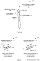
- FIG. 1 is a diagram illustrating various views of a bistable pitch propeller embodiment.
- FIG. 2 is a diagram illustrating an embodiment of a hover mode envelope and a forward flight mode envelope.
- FIG. 3 is a state diagram illustrating an embodiment of states associated with a bistable pitch propeller.
- FIG. 5A is a diagram showing an embodiment of a bistable pitch propeller with mechanical components to ensure that the two blades are in the same position at the same time.
- FIG. 5B is a diagram showing a side view without blades and a side view looking up of the exemplary bistable pitch propeller with mechanical components to ensure that the blades are in the same position.
- FIG. 5C is a diagram showing a side view with blades and a bottom view of the exemplary bistable pitch propeller with mechanical components to ensure that the blades are in the same position.
- FIG. 7A is a diagram illustrating an embodiment of a peg stopper which stops a peg connected to a bearing.
- FIG. 7B is a diagram illustrating an embodiment of a blade stopper which is designed to come into contact with and stop a blade.
- FIG. 8 is a diagram illustrating some embodiments of adjustable stoppers.
- FIG. 9 is a diagram illustrating an embodiment of a bistable pitch propeller, where the blades are configured to return to a resting position when the propeller is not rotating.
- FIG. 10 is a diagram illustrating an embodiment of a blade being held in a feathered blade position using a peg stopper.
- FIG. 11 is a flowchart illustrating various embodiments of user interfaces associated with adjusting the position of a blade.
- FIG. 12A is a flowchart illustrating an embodiment of a process to receive a desired blade pitch from a user interface and adjust the position of a mechanical stop accordingly.
- FIG. 12B is a flowchart illustrating an embodiment of a process to receive a desired blade pitch from a user interface and adjust the position of a mechanical stop accordingly where the user interface is disabled if the mechanical stop is in use.
- FIG. 12C is a flowchart illustrating an embodiment of a process to receive a desired blade pitch from a user interface and adjust the position of a mechanical stop accordingly where the desired blade pitch is held until the mechanical stop is free.
- FIG. 13A is a flowchart illustrating an embodiment of a process to receive a desired mode from a user interface and adjust the position of a mechanical stop accordingly.
- FIG. 13B is a flowchart illustrating an embodiment of a process to receive a desired mode from a user interface and adjust the position of a mechanical stop accordingly where the user interface is disabled if the mechanical stop is in use.
- FIG. 13C is a flowchart illustrating an embodiment of a process to receive a desired mode from a user interface and adjust the position of a mechanical stop accordingly where the desired mode is held until the mechanical stop is free.
- the invention can be implemented in numerous ways, including as a process; an apparatus; a system; a composition of matter; a computer program product embodied on a computer readable storage medium; and/or a processor, such as a processor configured to execute instructions stored on and/or provided by a memory coupled to the processor.
- these implementations, or any other form that the invention may take, may be referred to as techniques.
- the order of the steps of disclosed processes may be altered within the scope of the invention.
- a component such as a processor or a memory described as being configured to perform a task may be implemented as a general component that is temporarily configured to perform the task at a given time or a specific component that is manufactured to perform the task.
- the term ‘processor’ refers to one or more devices, circuits, and/or processing cores configured to process data, such as computer program instructions.
- a propeller that is mechanically stable in two (or more) different positions depending on the propeller's rotational speed (e.g., where the propeller always rotates in the same direction) is disclosed.
- a propeller blade of the propeller system may be mounted so as to be rotatable about an at least roughly longitudinal axis of the blade.
- the blade is constructed and mounted such that the rotation of the propeller at a first rotational speed causes the blade to rotate (if/as necessary) about the longitudinal axis to a first stable position in which a portion of the blade and/or a structure coupled mechanically to the blade engages a mechanical stop, resulting in the blade presenting a first angle of attack.
- Rotation of the propeller at a second rotation speed results in the blade rotating (if/as necessary) about the longitudinal axis to a second stable position in which a portion of the blade and/or a structure coupled mechanically to the blade engages a magnetic stop, resulting in the blade presenting a second angle of attack.
- aerodynamic forces act on the propeller blade to rotate the blade about its longitudinal axis to reach and/or maintain the first or second stable state, as applicable.
- other forces e.g., in addition to or as an alternative to aerodynamic forces
- cause the blade(s) to rotate such as torque or centripetal force.
- FIG. 1 is a diagram illustrating various views of a bistable pitch propeller embodiment.
- the bistable pitch propellers described in this figure and below are merely exemplary and are not intended to be limiting.
- two blades are shown in this figure, any number of blades may be employed.
- the shape of the blade e.g., any washout, the blade thickness, the blade width, any tapering, etc.
- the position of the axis of rotation, the position of the aerodynamic center, and the position of the center of mass are merely exemplary and are not intended to be limiting.
- diagram 100 shows a top view of the exemplary bistable pitch propeller, which in this example has two blades ( 102 ). Each blade is connected to a bearing ( 104 ), which permits the blade to rotate about an axis of rotation of the blade ( 106 ), sometimes referred to as the longitudinal axis.
- a first rotational speed e.g., in or associated with a first flight envelope
- the blades pivot on their respective bearings about the axis of rotation of the blade ( 106 ).
- the blades are relatively lightweight (e.g., to make rotation of the blades about the axis of rotation easier) and the rotation of the propeller causes an aerodynamic force to be applied to the aerodynamic center ( 108 ) of the blade. Since the aerodynamic center is not on the axis of rotation, the blade rotates when the propeller rotates.
- Diagram 112 shows a cross section of one of the blades when that blade is in a hovering mode or configuration.
- the relatively high rate of rotation of the propeller causes the blade to be pushed because of the aerodynamic force applied to the blade and the blade's ability to rotate about its longitudinal axis ( 106 ) (e.g., because of the bearing).
- the aerodynamic force is sufficiently strong to push and hold the blade against the mechanical stopper ( 114 ), holding the blade in that position and at that pitch (i.e., an angle relative to a plane in which the propeller is being rotated).
- Diagram 112 thus shows a first blade pitch (or, more generally, blade position) at which the pitch propeller is stable in (e.g., the blade is rigid in this position and will not move so long as the propeller is being rotated at a sufficient rate).
- the propeller needs to be rotated at a rate of 3000 rpm or greater in order for the aerodynamic force to be sufficiently strong (e.g., to “pin” blades down to a sufficient degree).
- the blade pitch is cu, where cu is relatively small. A flatter blade is therefore presented to the relative wind. This flatter blade pitch provides more upward thrust and therefore is good for hovering where upward thrust is desired.
- ⁇ 1 may be defined as 0 degrees, and the blade tip might in that case have a twist angle of 10-20 degrees.
- an aircraft may be able to hover when the blade(s) is/are in some other position (e.g., a forward flight position, as is shown in diagram 116 ), the blade(s) may be put into this position when the aircraft is hovering in order to improve flight performance and/or reduce noise.
- Diagram 116 shows a cross section of one of the blades when the propeller rotates at a slower rotational speed (e.g., in or associated with a second flight envelope).
- the slower rotational speed of the propeller e.g., in the same direction as in diagram 112
- the blade ( 102 ) lifts off of the stopper and is pulled toward magnet 114 and is held against the magnet.
- This blade position (pitch) is referred to as a second blade position (pitch).
- the blade pitch is ⁇ 2 where ⁇ 2 > ⁇ 1 .
- the blade pitch presented to the relative wind in this position is therefore steeper.
- ⁇ 2 may be within an angular range of 20 to 30 degrees and might therefore have a blade twist that is 30 to 50 degrees at the tip.
- This steeper blade pitch offers better performance for forward flight, but is not as good for hovering, and may in fact stall in hover.
- the blade pitch (or, more generally, blade position) shown in diagram 116 is therefore an example of a second blade pitch (or, more generally, blade position) which the pitch propeller is stable in and the blade may be put into this position when the aircraft is in a forward flight mode.
- the following figures illustrate some example flight mode envelopes associated with a bistable pitch propeller.
- FIG. 2 is a diagram illustrating an embodiment of a hover mode envelope and a forward flight mode envelope.
- diagram 200 shows a graph where the x-axis is the forward velocity of an aircraft and the y-axis is the rotational speed (in this example in rotations per minute (RPM)) of a bistable pitch propeller of the aircraft.
- RPM rotations per minute
- the rotational speed of a propeller is completely controllable and the forward velocity is dependent to some degree upon to the rotational speed of the propeller (e.g., the propeller causes the aircraft to move and so the forward velocity depend upon the rotational speed of the propeller, the position of the aircraft, the position of the blades, etc.).
- the force(s) which cause the blades to switch position may be some combination of aerodynamic force, torque, and/or centripetal force.
- aerodynamic force, torque, and centripetal force depend upon the RPM of the propeller and the forward velocity of the aircraft and so a flight envelope may be expressed in a variety of combinations of metrics (e.g., RPM and torque, RPM and aerodynamic force, etc.).
- Hover mode envelope 202 is associated with the combination of forward velocities and rotational speeds at which the blades of the bistable pitch propeller will (e.g., always or consistently) be in a hover mode or configuration.
- the blade would be in the blade position shown in diagram 112 in FIG. 1 .
- Forward flight mode envelope 202 is associated with the forward velocities and rotational speeds at which the blades of the bistable pitch propeller will (e.g., always or consistently) be in a forward flight mode or configuration. For example, in this region, the blade would be in the blade position shown in diagram 116 in FIG. 1 .
- the position of the blades is not known.
- the blades could, for example, be in the first blade position (e.g., pinned against stopper 114 as shown in diagram 112 in FIG. 1 ), the second blade position (e.g., held against magnet 114 as shown in diagram 116 in FIG. 1 ), or at some blade position between the two (e.g., dangling and not in a stable or “firm” position). Therefore, to ensure that the blades are in a known position, the aircraft is operated in hover mode envelope 202 or forward flight mode envelope 206 .
- the propeller is slowed down to an RPM (and forward flight speed) that falls within the forward flight mode envelope ( 206 ).
- RPM and forward flight speed
- the propeller is slowed down to go from (RPM 1 , ⁇ forward,1 ) to (RPM 2 , ⁇ forward,1 ).
- the forward velocity stays the same when the propeller is slowed down, in some other cases the forward velocity changes (e.g., slows) in response to the change in propeller rotational speed.
- the blades are still able to switch to a forward flight configuration so long as the end data point falls within the forward flight mode envelope ( 206 ).
- the propeller is sped up to an RPM (and forward flight speed) that falls within the hover mode envelope ( 202 ).
- RPM and forward flight speed
- the propeller is sped up from (RPM 2 , ⁇ forward,2 ) to (RPM 1 , ⁇ forward,2 ).
- the forward speed may change in response to the propeller being sped up and this is acceptable so long as the end data point falls within hover mode envelope 202 .
- the propeller is sped up and slowed down during the transition with some margin such that the end data point does not fall on border 208 or on border 210 .
- the same RPM is used (e.g., regardless of the forward velocity of the aircraft) when the blades are switch from forward flight mode to hover mode (or vice versa).
- this would mean always spinning up the propeller to RPM 1 when putting the blades into a hover configuration (e.g., regardless of forward velocity) and always spinning down the propeller to RPM 2 when putting the blades into a forward flight configuration (e.g., regardless of forward velocity). In some applications this is attractive because it is an easy-to-implement design.
- the propeller may be spun up or down until the RPM and forward velocity reach a point in the hover mode envelope or forward flight mode envelope (e.g., with some margin, if desired). For example, to transition the blades from hover mode to forward flight mode, the propeller may be spun down a little and the forward velocity may be measured. If that data point (e.g., the combination of the new, slower RPM and the measured forward flight) is in the forward flight mode envelope (e.g., with sufficient margin, if desired), then the switch has completed and the process ends. If not, the propeller is slowed down some more, the forward velocity is measured again, and another check is performed. In some applications, this approach is attractive because the propeller does not need to be spun up/down unnecessarily in order to switch the blade position (e.g., which may produce a less jerky and/or smoother flight experience).
- the propeller may be rotated at any desired speed (e.g., so long as it is within the appropriate envelope, otherwise the blades will switch position again). For example, when the blades switch position, the propeller may be spun up or slowed down briefly and then the propeller is returned to some operational or desired rotational speed.
- FIG. 3 is a state diagram illustrating an embodiment of states associated with a bistable pitch propeller.
- FIG. 3 continues the example of FIG. 2 where there is a forward flight mode envelope, a hovering mode envelop, and an undefined region.
- the propeller instructions e.g., stop, rotate at a particular speed in a particular envelope, etc.
- a flight computer e.g., implemented using a processor and memory
- a bistable pitch propeller is stable in a first position.
- a propeller which includes a rotatable blade, is rotated at a speed which falls into a first envelope (see, e.g., hover mode envelope 202 in FIG. 2 ).
- the rotation of the propeller in this region causes the rotatable blade to be in a first blade position.
- a blade may be able to rotate because it is connected to a bearing which is able to rotate.
- the rotation of the propeller causes an aerodynamic force (as an example) to push the blade ( 102 ) against the stopper ( 114 ), holding blade ( 102 ) in the first blade position shown therein.
- the blade pitch shown i.e., ⁇ 1
- a propeller may be put into state 300 when the aircraft is hovering or is transitioning to hovering.
- the bistable pitch propeller is stable in a second state.
- the propeller is rotated at a speed which falls into a second envelope (see, e.g., or forward flight mode envelope 206 in FIG. 2 ).
- the rotation of the propeller in this region causes the rotatable blade to be in a second blade position different from the first blade position. See, for example, diagram 116 in FIG. 1 which shows the blade ( 102 ) in a second blade position.
- the different blade positions include different blade pitches where ⁇ 1 ⁇ 2 .
- the blade position in this diagram is better for forward flight and so (as an example) a propeller may be put into state 302 when the aircraft is in forward flight or is transitioning to forward flight.
- the propeller goes into the stopped state ( 304 ).
- the actual position of the propeller's blades in the stopped state may depend upon what position the blade was in before the propeller stopped. For example, if the blade was positioned against the magnetic stop, then the magnetic force from the magnetic stop will continue to pull against the blade, holding it in position even after the propeller stops.
- the propeller goes into the undefined state ( 306 ).
- the blade may be in the first blade position (e.g., an angle which is good or better for hovering), the second blade position (e.g., an angle which is good or better for forward flight), or some in-between position.
- the following figure illustrates an example of an aircraft which uses a bistable pitch propeller.
- the aircraft shown is merely exemplary and is not intended to be limiting.
- FIG. 4 is a diagram illustrating an embodiment of an octocopter which includes bistable pitch propellers.
- all of the octocopter's propellers are bistable pitch propellers.
- some other types of aircraft may be configured differently.
- Diagram 400 shows a top view of the octocopter.
- Diagram 402 shows a side view of the octocopter when the octocopter is in a hovering position. From this view, it is apparent that the plane of the octocopter (e.g., created by the four crossbars ( 404 ) to which the eight propellers are attached) is horizontal when hovering. In this mode, it is desirable for the propellers to be optimized for hovering, and the propellers may be rotated at a speed which causes the bistable pitch propellers to have their blades be in a position which is optimized for hovering.
- the octocopter flips up so that the plane created by the crossbars ( 404 ) is vertical.
- diagram 406 shows a side view of the octocopter in a transitional position where the plane created by the crossbars is at a diagonal.
- Diagram 408 shows a side view of the octocopter in forward flight, where the plane created by the crossbars is in a vertical position.
- the octocopter flips up by selectively spinning the propellers at different rotational speeds to create a lift differential (e.g., the propellers are fixed to the crossbars and they cannot be angled or repositioned). This lift differential causes one side of the octocopter to flip up (e.g., the left side from the side views shown in diagrams 402 , 406 , and 408 .
- the position or mode of the octocopter and propellers are independent and the octocopter can be in one mode (e.g., forward flight) while the propeller is in the other mode (e.g., hovering).
- the propellers may not be switched from hovering mode to forward flight mode until the octocopter has flipped up to a forward flight position (see diagram 408 ).
- the blades of the propellers would therefore temporarily be at an angle that better suited to hovering while the octocopter is in forward flight position (e.g., at least until the blades of the propellers were switched to the more efficient forward flight mode).
- the performance may not be optimal (e.g., it may be noisy or not as efficient), it may still be acceptable.
- the following figures illustrate an example of a bistable pitch propeller system with mechanical components to ensure that the blades are in the same position at the same time. For example, if one blade is in one position (e.g., hovering mode) and the other blade is in another position (e.g., forward flight mode), the propeller may experience a significant amount of vibration.
- the exemplary bistable pitch propeller system described below prevents this from occurring.
- FIG. 5A is a diagram showing an embodiment of a bistable pitch propeller with mechanical components to ensure that the two blades are in the same position at the same time.
- Diagram 500 shows a side view of the exemplary bistable pitch propeller where both the first blade ( 502 ) and the second blade ( 504 ) are shown.
- the first blade ( 502 ) and the second blade ( 504 ) are both are in a first (e.g., hovering) blade position.
- the blade positions shown here are associated with hovering mode envelope 202 shown in FIG. 2 .
- Diagram 506 shows a cutaway view without the first blade ( 502 ) which better shows the inner mechanical components. As shown in diagram 506 , peg 506 prevents part 508 from moving any further and thus second blade is held in a mechanically stable position. As described above, an aerodynamic force causes the second blade ( 504 ) to rotate, in this diagram pushing part 508 into peg 506 .
- the blade position shown in diagram 500 and diagram 506 is referred to herein as the first blade position.
- the bistable pitch propeller is rotated at a speed and has a forward velocity that falls in the other flight envelope. This would cause the blades flip to the second blade position such that part 512 (e.g., part of or connected to second blade 504 ) is stopped by magnet 510 .
- part 512 e.g., part of or connected to second blade 504
- magnet 510 magnet 510 .
- the blades are held against the magnet (not shown), the blades are in a stable position; this is an example of a second blade position.
- the bistable pitch propeller embodiment shown here includes mechanical components to ensure that first blade and the second blade are both in the same blade position at the same time. For example, suppose that the second blade ( 504 ) in diagram 506 rotates so that peg 506 and part 508 separate and magnet 510 and part 512 move closer to each other. The tip of part 508 is long enough to touch the back of part 514 if the first blade (not shown in diagram 506 ) remains in the first blade position. Thus, if the first blade somehow got stuck in the first blade position, part 508 from the second blade would push the first blade into the second blade position. This would prevent the first blade ( 502 ) from being in the first blade position while the second blade ( 504 ) switched to the second blade position.
- the exemplary bistable pitch propeller has components which force the two blades to be in the same blade position, preventing the blades from being in different blade positions.
- FIGS. 5B and 5C show additional views of the exemplary bistable pitch propeller with mechanical components to ensure that the blades are in the same position.
- Diagram 520 shows a side view without blades
- diagram 522 shows a side view looking up
- diagram 524 shows a side view with blades
- diagram 526 shows a bottom view.
- the following process is used to (e.g., automatically) detect when this occurs and force the blades into the same blade position.
- FIG. 6 is a flowchart illustrating an embodiment of a process to automatically detect when there is a significant amount of vibration in a bistable pitch propeller.
- the process may be used with embodiments of the bistable pitch propeller where there are no components to ensure that the two blades are at the same blade angle.
- an amount of vibration associated with the bistable pitch propeller is measured.
- an aircraft may have multiple propellers and so in some embodiments there is a vibration sensor for each bistable pitch propeller.
- the measured amount of vibration is greater than a threshold. For example, there may be some expected or normal degree of vibration and the threshold is set to some value well beyond that.
- the process continues to measure the amount of vibration at step 600 . If the measured amount of vibration is determined to be less than the threshold at 602 , the process continues to measure the amount of vibration at step 600 . If the measured amount of vibration is determined to be greater than the threshold at 602 , a desired blade position is determined. In some embodiments, the desired blade position is the last blade position or angle the bistable pitch propeller was put into (e.g., a last programmed position). For example, if a given bistable pitch propeller was put into a hovering mode and then one of the blades inadvertently switched to a forward flight position or angle, the desired blade position would be the hovering mode or angle.
- the rotational speed of the propeller is temporarily increased.
- it may be a relatively high speed well above some a borderline speed to ensure that the blades are forced into the first position.
- the rotational speed of the propeller is temporarily decreased.
- it may be a relatively low speed well below some a borderline speed to ensure that the blades are forced into the second position.
- the propeller may be returned to its previous rotational speed.
- the vibration of that propeller is measured again (e.g., at step 600 ) and compared against a threshold again (e.g., at step 602 ) to ensure the blades were forced into the same position or angle. If not, the process may be repeated again.
- the process tries to fix one propeller at a time.
- the aircraft may be unstable if too many propellers are sped up very quickly or slowed down very quickly at the same time.
- blade is first put into this position (e.g., to quickly stop the excessive vibration). For example, this may occur before step 606 or step 608 . Then, the process may try to put the propeller into the desired blade position (e.g., by performing step 606 or step 608 ).
- stoppers may be employed for the mechanical and/or magnetic stopper and the stopper shown in FIG. 1 is merely one example.
- the following figures illustrate some other examples.
- FIG. 7A is a diagram illustrating an embodiment of a peg stopper which stops a peg connected to a bearing.
- diagram 700 shows a side view when the blade is stopped by the exemplary peg stopper; for clarity only a single stopper is shown.
- a cross section of the blade e.g., looking towards the nose piece from the tip of the blade
- the blade cross section shown in this figure is transparent.
- the longitudinal axis of rotation of the blade extends out of the page from the center of the bearing ( 702 ).
- the aerodynamic center of the blade (also not shown) is at a height below the height of the axis of rotation of the blade. This permits the bottom portion of the blade to be pushed by an aerodynamic force either towards the peg stopper.
- bearing 702 is able to rotate.
- an aerodynamic force pushes on the blade, which causes the blade and the bearing to rotate towards the peg stopper ( 706 ).
- a peg ( 704 ) is attached to and radiates outward from the bearing ( 702 ) and the bearing rotates until the peg is stopped by the peg stopper ( 706 ).
- the peg stopper is connected to the nose piece ( 712 ) so that the peg stopper can stop the peg from moving further, even while the propeller rotates.
- a peg stopper is attached to the nose piece to stop the peg at the appropriate position (e.g., to achieve a steeper blade angle or a more feathered blade angle).
- the blade position or pitch shown here is merely exemplary and is not intended to be limiting. Some examples are described below where the position of a stopper is adjustable so that the first blade position and/or second blade position is/are not necessarily fixed (e.g., the peg stoppers are not welded directly to the nose piece, which would cause them to remain in a fixed position).
- a peg and bearing may comprise a single piece of metal or other material (e.g., the peg and bearing are cast or cut as a single piece of metal).
- a peg and/or a peg stopper may comprise a variety of shapes and/or materials.
- a peg stopper may be made of metal (e.g., for strength and/or durability) and have a rubber sleeve or cover (e.g., to cushion the peg which may be pushed forcefully into the peg stopper, given the expected high propeller speeds).
- a peg stopper has substantially the same height as a peg (e.g., to increase the area where the peg and peg stopper come into contact which better distributes the pressure and/or to more securely attach the peg stopper to the nose piece).
- the peg and peg stopper have matching surfaces where they come into contact with each other (e.g., both have a flat surface where they make contact and the flat surfaces match up) to increase the area where they come into contact with each other.
- the following figure shows a different embodiment where a stopper is designed to come into direct contact with the blade (e.g., as opposed to this figure).
- FIG. 7B is a diagram illustrating an embodiment of a blade stopper which is designed to come into contact with and stop a blade.
- diagram 720 shows a side view when the blade is stopped by the exemplary blade stopper; for clarity only a single stopper is shown.
- An aerodynamic force pushes against the blade ( 722 ), causing the bearing ( 724 ) which is attached to the blade to rotate.
- the rotation of the blade and bearing is stopped when one (e.g., substantially flat) side of the blade ( 726 ) comes into contact with a blade stopper ( 728 ); this holds the blade in a first blade position when the propeller is rotating in the direction shown.
- Diagram 732 shows a top view; for clarity, the blade is not shown. As is shown in this view, the blade stopper ( 728 ) is attached to the nose piece ( 730 ), radiating outward so that it can make contact with the blade (not shown).
- the exemplary blade cross section shown here has a relatively simple design or shape but this is not intended to be limiting.
- a blade used in a real-world embodiment may have a design or shape which is optimized to achieve a variety of design and/or performance objectives.
- a blade stopper may vary.
- the shape of the blade stoppers may be aerodynamic since the propeller is expected to have a relatively high rate of rotation.
- a blade stopper is made of metal with a rubber sleeve or cover.
- the position of a stopper is adjustable, such that the first blade position and/or the second blade position is adjustable.
- the following figure illustrates some examples of adjustable stoppers.
- FIG. 8 is a diagram illustrating some embodiments of adjustable stoppers. For clarity only a single adjustable stopper is shown in each diagram.
- Diagram 800 shows a side view of an adjustable peg stopper.
- the position of the peg stopper ( 802 ) can be positioned anywhere within the cutout ( 804 ).
- the blade position e.g., when the peg is stopped by the peg stopper
- the shape of the cutout is merely exemplary and is not intended to be limiting.
- the cutout is L-shaped, vertical, horizontal, diagonal, etc.
- the peg stoppers are designed to be manually adjusted, for example, using an exposed knob or using a screwdriver to turn an exposed screw head. Turning the screw head or knob in turn causes a corresponding peg stopper to move (for example) clockwise/counterclockwise, up/down, left/right within a cutout.
- the nose piece ( 810 ) includes actuators which permit the automatic (that is, non-manual) adjustment of the first and/or second peg stoppers within the first and second cutouts, respectively.
- the second peg stopper can be moved within the second cutout using the appropriate actuator. Then, when the propeller is rotated in the other direction, the new position of the second peg stopper will cause the blade to stop in a new, second blade position.
- Diagram 814 illustrates a side view of an example of an L-shaped, telescoping blade stopper.
- the blade stopper ( 816 ) is telescoping, which permits the length of the blade stopper to be adjusted. This, in turn, stops the blade at varying blade positions or blade pitches when the propeller is rotated in the appropriate direction. Since a blade will come into contact with a telescoping blade stopper at a variety of angles (e.g., depending upon the height of the stopper), a telescoping blade stopper has rounded ends where the stopper comes into contact with a side of the blade. In some embodiments, some other tip shape is used. In some embodiments, the end or tip of a telescoping blade stopper is rubberized.
- the adjustment mechanism is a manual adjustment mechanism and in other embodiments the adjustment mechanism is an automatic adjustment mechanism.
- the ability to adjust the first and/or second blade position may be especially desirable in wind turbine applications.
- the pitch of the blade is adjusted depending upon wind strength. When the wind is too strong and too much electricity is being generated, the pitch of the blade is adjusted so that the blades are more feathered, reducing the amount of electricity produced. If the wind dies down too much, then the pitch of the blade may be adjusted so that the blades are at a steeper angle, increasing the amount of electricity produced.
- the blades of a bistable pitch propeller are configured to return to a certain position when the propeller is not rotating.
- the following figure shows one such example.
- FIG. 9 is a diagram illustrating an embodiment of a bistable pitch propeller, where the blades are configured to return to a resting position when the propeller is not rotating.
- the resting position is a feathered position.
- diagram 900 shows the nose piece ( 902 ) with two internal springs ( 904 a and 904 b ).
- the first internal spring and second internal spring therefore collectively push the blade to the center (i.e., a feathered position).
- the internal springs are relatively weak such that when the propeller is rotating, the expected aerodynamic force is greater than the force exerted by the internal springs and the blades can be pushed and held in the first or second blade position.
- Diagram 910 shows an interior view of the nose piece.
- part of the bearing (not shown in diagram 910 ) is connected to a spring-mounted ball bearing ( 914 ). It is noted that the spring-mounted ball bearing ( 914 ) is different from bearing 912 .
- the spring-mounted ball bearing is in position 916 .
- the spring-mounted ball bearing is in position 918 .
- the internal springs shown in diagram 900 will cause the spring-mounted ball bearing to come to a rest in position 620 (i.e., the resting, feathered position when the propeller is not rotating).
- the placement of the “dip” or minima in the sloped surface therefore dictates where the resting position will be.
- the slope(s) e.g., between positions 916 , 920 , and 918
- the springs are relatively weak. This permits the expected aerodynamic force to push the blade (e.g., at rest) out of the resting position shown and into the first or second blade position when the propeller is rotating.
- the mechanisms shown here which cause the blade to go to a resting position (in this example, a feathered position) when the propeller is not rotating are merely exemplary and are not intended to be limiting. Any (e.g., mechanical) mechanism which returns the blade to some desired resting position when the propeller is not rotating may be used.
- the feathered blade position shown here be one of the blade positions created or defined by a stopper.
- the following figure shows an example of this.
- FIG. 10 is a diagram illustrating an embodiment of a blade being held in a feathered blade position using a peg stopper.
- a peg stopper embodiment is shown, but naturally the concepts may be extended to other embodiments.
- a bearing ( 1000 ) which is able to rotate has a peg ( 1002 ) attached to it.
- the bistable pitch propeller is being used in a wind turbine application, then it may be desirable to have one of the blade positions defined or created by a stopper be a feathered blade position. The blades may be put into this position when the wind is too strong (e.g., there is a storm) and too much electricity is being generated.
- the position of a stopper (and thus a blade position when a bistable pitch propeller is rotating) is adjustable in some embodiments.
- the following figure illustrates some example user interfaces which may be presented to a pilot or user when there is an automatic adjustment mechanism (e.g., as opposed to a manual adjustment).
- FIG. 11 is a flowchart illustrating various embodiments of user interfaces associated with adjusting the position of a blade.
- the user interface is presented to a pilot or other user by a flight computer (e.g., implemented using a processor and memory) when a stopper has an automatic adjustment mechanism.
- a flight computer e.g., implemented using a processor and memory
- User interface 1100 shows an example of a user interface where the pilot or user is permitted to specify the desired blade pitches (e.g., explicitly).
- the user can input a number (in this example, between 0° and 90° in input box 1102 a and press the set button ( 1104 a ).
- the flight computer then moves the corresponding adjustable stopper (see, for example, FIG. 8 ) to a position which corresponds to the specified blade pitch.
- a desired blade pitch can be specified for the second blade pitch using input box 1102 b and set button 1104 b.
- User interface 1106 shows an example of a user interface where the pilot or user selects a flight mode from a plurality of presented flight modes.
- user interface 1106 permits the pilot or user to select a hover mode, a forward flight mode, a wind turbine mode when the wind is weak, a wind turbine mode when the wind is moderate, or a wind turbine mode when the wind is strong (i.e., a feathered mode).
- the desired mode is selected by clicking on the appropriate radio button and set button 1108 a is pressed.
- the second blade position can be set or otherwise adjusted by selecting the desired mode and pressing set button 1108 b .
- Each flight mode may have a corresponding stopper position (e.g., corresponding to a blade pitch which is optimized for that particular mode or application) and the appropriate stopper is moved to that stopper position.
- an aircraft includes multiple bistable pitch propellers. See, for example, FIG. 4 .
- the user interface may include independent controls for each bistable pitch propeller.
- a given stopper can only be adjusted at certain times (e.g., when the propeller is not rotating or when the blade is being held in position by the other stopper). If so, this may be handled by the user interface in a variety of ways in various embodiments.
- the user interface does not permit the pilot or user to specify a desired blade pitch or desired mode when a given stopper cannot be adjusted. For example, in user interface 1100 and user interface 1106 , the affected input box, radio buttons, and/or set button may be disabled and the user may not be able to select those controls and/or input values into those controls.
- the pilot or user is able to specify a desired blade pitch or desired flight mode at any time, but the user interface informs the pilot or user that the change will not be made right away.
- the user interface may be updated to inform the pilot or user that the change has been made.
- FIG. 12A is a flowchart illustrating an embodiment of a process to receive a desired blade pitch from a user interface and adjust the position of a mechanical stop accordingly.
- a desired blade pitch for the first position is received from a user interface. See, for example, user interface 800 in FIG. 8 .
- a new position for the mechanical stop is determined based at least in part on the desired blade pitch. For example, there may be some lookup table which maps the desired blade pitch to a corresponding position of the stopper.
- a position control for the mechanical stop is set to a value which corresponds to the new position. For example, a control for an actuator may be set to some value which causes the stopper to be moved to the new position determined at step 1202 .
- FIG. 12B is a flowchart illustrating an embodiment of a process to receive a desired blade pitch from a user interface and adjust the position of a mechanical stop accordingly where the user interface is disabled if the mechanical stop is in use.
- a mechanical stop it is determined if a mechanical stop is in use. For example, as described above, the mechanical stop may only be permitted to be moved if the propeller is not rotating or the magnetic stopper is the one currently holding the blade or peg in place.
- one or more controls associated with receiving a desired blade pitch for the first position are disabled in a user interface 1210 .
- a user would not be able to select and/or input values into input box 1102 a or set button 1104 a if the mechanical stop is holding the blade in the first blade position or pitch.
- the radio buttons and set button 1108 a may be disabled (e.g., un-selectable) if the mechanical stop is holding the blade in the first blade position or pitch. In this example, the process stays in this loop until the mechanical stop is no longer in use.
- the controls are enabled at 1214 . This, for example, permits the user to select the previously disabled controls.
- the desired blade pitch for the first position is received from the user interface.
- a new position is determined for the mechanical stop based at least in part on the desired blade pitch.
- a position control for the mechanical stop is set to a value which corresponds to the new position.
- FIG. 12C is a flowchart illustrating an embodiment of a process to receive a desired blade pitch from a user interface and adjust the position of a mechanical stop accordingly where the desired blade pitch is held until the mechanical stop is free. As before, steps previously described are not discussed in detail here for brevity.
- a desired blade pitch for the first position is received from a user interface.
- a message indicating that the desired blade pitch will not be immediately applied is displayed at 1222 .
- the process stays in this loop until the mechanical stop is no longer in use.
- the user interface permits a desired blade pitch to be specified or otherwise input, but then holds on to that pitch without actually making any changes until the relevant mechanical stop is no longer being used to hold or otherwise stop the blade or peg (as an example).
- the content of a message displayed at step 1222 may vary.
- the message is fairly simple (e.g., “Waiting”).
- the message identifies that the wait is due to the stopper being in use (e.g., “The blade pitch will be changed when the propeller is turned off or the propeller switches directions.”).
- a new position for the mechanical stop is determined based at least in part on the desired blade pitch at 1202 .
- a second message is displayed to the user, indicating that the desired blade pitch has been applied (e.g., “Done” or “The blade pitch has been changed”).
- a position control for the mechanical stop is set to a value which corresponds to the new position.
- FIG. 13A is a flowchart illustrating an embodiment of a process to receive a desired mode from a user interface and adjust the position of a mechanical stop accordingly.
- a desired mode for the first position is received from a user interface, wherein the desired mode is selected from a plurality of modes. See, for example, user interface 1106 in FIG. 11 where multiple modes are presented and the user selects one.
- a new position is determined for a mechanical stop based at least in part on the desired mode.
- each possible mode e.g., presented to the user
- a lookup table is used to map a desired mode to a new mechanical stop position.
- a position control for the mechanical stop is set to a value which corresponds to the new position.
- FIG. 13B is a flowchart illustrating an embodiment of a process to receive a desired mode from a user interface and adjust the position of a mechanical stop accordingly where the user interface is disabled if the mechanical stop is in use.
- a mechanical stop it is determined if a mechanical stop is in use. If so, one or more controls associated with receiving a desired mode for the first position are disabled in a user interface at 1313 . As described above, this may include making controls un-selectable and/or not permitting inputs or other values to be entered. In this example, the process stays in this loop until the first stopper is no longer in use.
- the controls are enabled at 1314 .
- the desired mode for the first position is received from the user interface, wherein the desired mode is selected from a plurality of modes.
- a new position for the mechanical stop is determined based at least in part on the desired mode.
- a position control for the mechanical stop is set to a value which corresponds to the new position.
- FIG. 13C is a flowchart illustrating an embodiment of a process to receive a desired mode from a user interface and adjust the position of a mechanical stop accordingly where the desired mode is held until the mechanical stop is free. As before, steps that have been previously discussed are not discussed in detail here for brevity.
- a desired mode for the first position is received from a user interface, wherein the desired mode is selected from a plurality of modes.
- a new position is determined for the mechanical stop based at least in part on the desired mode at 1302 .
- a new or second message is displayed, for example indicating that the mechanical stop has been adjusted to reflect the desired mode.
- a position control for the mechanical stop is set to a value which corresponds to the new position.
Landscapes
- Engineering & Computer Science (AREA)
- Aviation & Aerospace Engineering (AREA)
- Mechanical Engineering (AREA)
- Physics & Mathematics (AREA)
- Fluid Mechanics (AREA)
- Toys (AREA)
- Structures Of Non-Positive Displacement Pumps (AREA)
Abstract
Description
Claims (5)
Priority Applications (1)
| Application Number | Priority Date | Filing Date | Title |
|---|---|---|---|
| US16/584,570 US10933989B2 (en) | 2016-08-01 | 2019-09-26 | Bistable pitch propeller system with unidirectional propeller rotation |
Applications Claiming Priority (2)
| Application Number | Priority Date | Filing Date | Title |
|---|---|---|---|
| US15/225,028 US10569861B2 (en) | 2016-08-01 | 2016-08-01 | Bistable pitch propeller system with unidirectional propeller rotation |
| US16/584,570 US10933989B2 (en) | 2016-08-01 | 2019-09-26 | Bistable pitch propeller system with unidirectional propeller rotation |
Related Parent Applications (1)
| Application Number | Title | Priority Date | Filing Date |
|---|---|---|---|
| US15/225,028 Continuation US10569861B2 (en) | 2016-08-01 | 2016-08-01 | Bistable pitch propeller system with unidirectional propeller rotation |
Publications (2)
| Publication Number | Publication Date |
|---|---|
| US20200039634A1 US20200039634A1 (en) | 2020-02-06 |
| US10933989B2 true US10933989B2 (en) | 2021-03-02 |
Family
ID=61011508
Family Applications (2)
| Application Number | Title | Priority Date | Filing Date |
|---|---|---|---|
| US15/225,028 Active 2039-02-11 US10569861B2 (en) | 2016-08-01 | 2016-08-01 | Bistable pitch propeller system with unidirectional propeller rotation |
| US16/584,570 Active US10933989B2 (en) | 2016-08-01 | 2019-09-26 | Bistable pitch propeller system with unidirectional propeller rotation |
Family Applications Before (1)
| Application Number | Title | Priority Date | Filing Date |
|---|---|---|---|
| US15/225,028 Active 2039-02-11 US10569861B2 (en) | 2016-08-01 | 2016-08-01 | Bistable pitch propeller system with unidirectional propeller rotation |
Country Status (4)
| Country | Link |
|---|---|
| US (2) | US10569861B2 (en) |
| CN (1) | CN109476370B (en) |
| NZ (1) | NZ749462A (en) |
| WO (1) | WO2018026398A1 (en) |
Families Citing this family (6)
| Publication number | Priority date | Publication date | Assignee | Title |
|---|---|---|---|---|
| US20170355447A1 (en) * | 2016-06-10 | 2017-12-14 | Gopro, Inc. | Thrust-Dependent Variable Blade Pitch Propeller |
| US10569861B2 (en) * | 2016-08-01 | 2020-02-25 | Kitty Hawk Corporation | Bistable pitch propeller system with unidirectional propeller rotation |
| US20200140073A1 (en) * | 2018-11-05 | 2020-05-07 | Amazon Technologies, Inc. | Passive variable pitch propellers |
| US12441464B1 (en) | 2019-09-09 | 2025-10-14 | Sifly Aviation, Inc. | Rotor system for electrically powered rotorcraft |
| US12049305B1 (en) * | 2019-09-09 | 2024-07-30 | Sifly Aviation, Inc. | Rotor system for electrically powered rotorcraft |
| IL278565B (en) * | 2020-11-08 | 2021-04-29 | Bar Hagay | Skimmer group for firefighting |
Citations (14)
| Publication number | Priority date | Publication date | Assignee | Title |
|---|---|---|---|---|
| US2444539A (en) | 1943-05-11 | 1948-07-06 | Roy E Sharpes | Propeller mounting |
| US2455378A (en) | 1943-11-27 | 1948-12-07 | Howard M Mccoy | Mechanism and controls for controllable aircraft propellers; complete propeller with automatic controls |
| US3017932A (en) | 1957-01-10 | 1962-01-23 | Rotol Ltd | Control systems for aircraft propellers |
| US3207227A (en) | 1961-08-12 | 1965-09-21 | Dehavilland Aircraft | Variable pitch propeller control system |
| US3220484A (en) | 1963-04-11 | 1965-11-30 | Dowty Hydraulic Units Ltd | Cooling fans |
| US5104291A (en) | 1988-03-28 | 1992-04-14 | Morrison Douglas M | Variable pitch propeller blade hub and drive and adjusting mechanism therefor |
| US5551649A (en) * | 1989-10-20 | 1996-09-03 | Fokker Aircraft B.V. | Propeller blade position controller |
| US5593280A (en) | 1994-10-20 | 1997-01-14 | Honda Giken Kogyo Kabushiki Kaisha | Propeller for boat |
| US20050226727A1 (en) | 2004-03-03 | 2005-10-13 | Dennis Brian D | Methods and systems for controlling the pitch of a propeller |
| US7462015B2 (en) | 2005-04-27 | 2008-12-09 | Eurocopter | Rotocraft rotor with hinged blades and lockable retractable flapping abutments |
| US20110229319A1 (en) | 2010-03-18 | 2011-09-22 | Rolls-Royce Plc | Controlling blade pitch angle |
| US8790081B1 (en) | 2007-11-02 | 2014-07-29 | Auburn University | Constant torque propeller mechanism |
| US20150183510A1 (en) | 2013-12-30 | 2015-07-02 | Google Inc. | Dual-Pitch Support for a Propeller |
| US10569861B2 (en) * | 2016-08-01 | 2020-02-25 | Kitty Hawk Corporation | Bistable pitch propeller system with unidirectional propeller rotation |
Family Cites Families (15)
| Publication number | Priority date | Publication date | Assignee | Title |
|---|---|---|---|---|
| DE1045812B (en) * | 1955-12-01 | 1958-12-04 | Hartzell Industries | Propeller with automatically adjustable pitch of the propeller blades |
| US6213713B1 (en) * | 1998-12-31 | 2001-04-10 | United Technologies Corporation | Apparatus for indicating pitch angle of a propeller blade |
| FR2882543B1 (en) * | 2005-02-28 | 2008-10-10 | Eurocopter France | DEVICE FOR LOCKING A FIXING STRUCTURE OF A BLADE BY MEANS OF A ROTOR OF A GIRAVION |
| NZ555848A (en) * | 2007-06-12 | 2010-04-30 | Storm Rider Holdings Ltd | Improved wind generator |
| RU2371354C2 (en) * | 2007-12-28 | 2009-10-27 | Зубков Сергей Геннадьевич | Method to control flight in expanded range of speeds with controlled thrust-vector rotors |
| DE102008011139A1 (en) * | 2008-02-26 | 2009-08-27 | Nordex Energy Gmbh | Controller for a blade pitch of at least one rotor blade of a wind turbine |
| GB2460441A (en) * | 2008-05-30 | 2009-12-02 | Gilo Ind Ltd | Flying machine |
| US20100209244A1 (en) * | 2009-02-18 | 2010-08-19 | Gary Listen Lacy | Remotely controlled and electronically operated variable-pitch sailboat propeller |
| FR2951696B1 (en) * | 2009-10-22 | 2011-12-23 | Snecma | SYSTEM FOR VARYING THE IMPACT OF THE BLADES OF AN AIRCRAFT TURBOMACHINE PROPELLER USING A BRUSHLESS ELECTRIC MOTOR |
| FR2956856A1 (en) * | 2010-02-26 | 2011-09-02 | Eurocopter France | ADAPTIVE WHEEL BLADE AND ROTOR WITH SUCH BLADE |
| CN102011702B (en) * | 2010-05-28 | 2013-04-17 | 曹连芃 | Mechanism for controlling propeller pitch angle of vertical-axis wind turbine with magnetic force and wind power |
| WO2013105926A1 (en) * | 2011-03-22 | 2013-07-18 | Aerovironment Inc. | Invertible aircraft |
| EP2923179B1 (en) * | 2012-11-21 | 2020-12-23 | Dynapar Corporation | Sensor and/or power harvesting apparatus having a wide dynamic range for responding to a driving rotational input |
| GB2518643B (en) * | 2013-09-26 | 2016-06-08 | Ge Aviat Systems Ltd | Propeller assembly and propeller blade retention assembly |
| US9540103B2 (en) * | 2014-06-24 | 2017-01-10 | Kitty Hawk Corporation | Passive deployment mechanism for lift fan |
-
2016
- 2016-08-01 US US15/225,028 patent/US10569861B2/en active Active
-
2017
- 2017-03-14 CN CN201780044943.6A patent/CN109476370B/en active Active
- 2017-03-14 NZ NZ749462A patent/NZ749462A/en unknown
- 2017-03-14 WO PCT/US2017/022332 patent/WO2018026398A1/en not_active Ceased
-
2019
- 2019-09-26 US US16/584,570 patent/US10933989B2/en active Active
Patent Citations (15)
| Publication number | Priority date | Publication date | Assignee | Title |
|---|---|---|---|---|
| US2444539A (en) | 1943-05-11 | 1948-07-06 | Roy E Sharpes | Propeller mounting |
| US2455378A (en) | 1943-11-27 | 1948-12-07 | Howard M Mccoy | Mechanism and controls for controllable aircraft propellers; complete propeller with automatic controls |
| US3017932A (en) | 1957-01-10 | 1962-01-23 | Rotol Ltd | Control systems for aircraft propellers |
| US3207227A (en) | 1961-08-12 | 1965-09-21 | Dehavilland Aircraft | Variable pitch propeller control system |
| US3220484A (en) | 1963-04-11 | 1965-11-30 | Dowty Hydraulic Units Ltd | Cooling fans |
| US5104291A (en) | 1988-03-28 | 1992-04-14 | Morrison Douglas M | Variable pitch propeller blade hub and drive and adjusting mechanism therefor |
| US5551649A (en) * | 1989-10-20 | 1996-09-03 | Fokker Aircraft B.V. | Propeller blade position controller |
| US5593280A (en) | 1994-10-20 | 1997-01-14 | Honda Giken Kogyo Kabushiki Kaisha | Propeller for boat |
| US20050226727A1 (en) | 2004-03-03 | 2005-10-13 | Dennis Brian D | Methods and systems for controlling the pitch of a propeller |
| US7462015B2 (en) | 2005-04-27 | 2008-12-09 | Eurocopter | Rotocraft rotor with hinged blades and lockable retractable flapping abutments |
| US8790081B1 (en) | 2007-11-02 | 2014-07-29 | Auburn University | Constant torque propeller mechanism |
| US20110229319A1 (en) | 2010-03-18 | 2011-09-22 | Rolls-Royce Plc | Controlling blade pitch angle |
| US8794920B2 (en) | 2010-03-18 | 2014-08-05 | Rolls-Royce Plc | Controlling blade pitch angle |
| US20150183510A1 (en) | 2013-12-30 | 2015-07-02 | Google Inc. | Dual-Pitch Support for a Propeller |
| US10569861B2 (en) * | 2016-08-01 | 2020-02-25 | Kitty Hawk Corporation | Bistable pitch propeller system with unidirectional propeller rotation |
Also Published As
| Publication number | Publication date |
|---|---|
| WO2018026398A1 (en) | 2018-02-08 |
| US20180029694A1 (en) | 2018-02-01 |
| US10569861B2 (en) | 2020-02-25 |
| CN109476370A (en) | 2019-03-15 |
| US20200039634A1 (en) | 2020-02-06 |
| CN109476370B (en) | 2022-07-29 |
| NZ749462A (en) | 2020-08-28 |
Similar Documents
| Publication | Publication Date | Title |
|---|---|---|
| US10933989B2 (en) | Bistable pitch propeller system with unidirectional propeller rotation | |
| US11702188B2 (en) | Bistable pitch propeller system with bidirectional propeller rotation | |
| US9957042B1 (en) | Bimodal propeller aircraft | |
| US10252796B2 (en) | Rotor-blown wing with passively tilting fuselage | |
| EP3297909B1 (en) | Convertible rotor aircraft | |
| US20190055003A1 (en) | Foldable propeller, power assembly and unmanned aerial vehicle | |
| CN205345321U (en) | Screw, power suit and unmanned vehicles | |
| EP2957502A1 (en) | Convertible helicopter ring member | |
| US20190168868A1 (en) | Rotor assembly for a rotorcraft with torque controlld collective pitch | |
| CN102438899A (en) | Co-rotating stacked rotor disks for improved hover performance | |
| JP2005289128A (en) | Pitch angle variable mechanism of counter-rotating wing and flying device having counter-rotating wing equipped with the mechanism | |
| CN115649430B (en) | Folding rotor, aircraft and rotor control system | |
| EP2865593B1 (en) | Pivoting blade counterweight | |
| JP2009173152A (en) | Helicopter, its rotor, and its control method | |
| CN114030608B (en) | Variable-diameter rotor wing device and variable-pitch control method thereof | |
| US9809300B1 (en) | Torque-sensitive locking and release mechanism for a bistable pitch propeller | |
| CN109407692A (en) | Vert Yaw control method under VTOL fixed-wing unmanned plane rotor mode | |
| US20020005455A1 (en) | Rotor control with negative collective in high speed auto-rotation | |
| CN205854495U (en) | Displacement rotor and include the multi-rotor aerocraft of this displacement rotor | |
| CN117163339A (en) | The tail motor base mechanism and its working method for assisting the stabilization of the tilting three-rotor flying-wing UAV | |
| NZ759225B2 (en) | Bistable pitch propeller system with bidirectional propeller rotation | |
| CN204184569U (en) | Autogyro | |
| CN204473133U (en) | New autogyro | |
| WO2015081460A1 (en) | Osprey aircraft control device |
Legal Events
| Date | Code | Title | Description |
|---|---|---|---|
| FEPP | Fee payment procedure |
Free format text: ENTITY STATUS SET TO UNDISCOUNTED (ORIGINAL EVENT CODE: BIG.); ENTITY STATUS OF PATENT OWNER: LARGE ENTITY |
|
| STPP | Information on status: patent application and granting procedure in general |
Free format text: APPLICATION DISPATCHED FROM PREEXAM, NOT YET DOCKETED |
|
| STPP | Information on status: patent application and granting procedure in general |
Free format text: DOCKETED NEW CASE - READY FOR EXAMINATION |
|
| AS | Assignment |
Owner name: ONE AERO, LLC, CALIFORNIA Free format text: SECURITY INTEREST;ASSIGNOR:KITTY HAWK CORPORATION;REEL/FRAME:054206/0714 Effective date: 20201020 |
|
| STCF | Information on status: patent grant |
Free format text: PATENTED CASE |
|
| CC | Certificate of correction | ||
| AS | Assignment |
Owner name: ONE AERO, LLC, CALIFORNIA Free format text: SECURITY INTEREST;ASSIGNOR:KITTY HAWK CORPORATION;REEL/FRAME:058029/0610 Effective date: 20210930 |
|
| AS | Assignment |
Owner name: ONE AERO, LLC, CALIFORNIA Free format text: SECURITY INTEREST;ASSIGNOR:KITTY HAWK CORPORATION;REEL/FRAME:059503/0382 Effective date: 20220318 |
|
| AS | Assignment |
Owner name: KITTY HAWK CORPORATION, CALIFORNIA Free format text: RELEASE BY SECURED PARTY;ASSIGNOR:ONE AERO, LLC;REEL/FRAME:063713/0367 Effective date: 20230519 Owner name: KITTY HAWK CORPORATION, CALIFORNIA Free format text: RELEASE OF SECURITY INTEREST;ASSIGNOR:ONE AERO, LLC;REEL/FRAME:063713/0367 Effective date: 20230519 |
|
| MAFP | Maintenance fee payment |
Free format text: PAYMENT OF MAINTENANCE FEE, 4TH YEAR, LARGE ENTITY (ORIGINAL EVENT CODE: M1551); ENTITY STATUS OF PATENT OWNER: LARGE ENTITY Year of fee payment: 4 |