US10931349B2 - User equipment and method for grant-free uplink transmission - Google Patents

User equipment and method for grant-free uplink transmission Download PDF

Info

Publication number
US10931349B2
US10931349B2 US16/418,288 US201916418288A US10931349B2 US 10931349 B2 US10931349 B2 US 10931349B2 US 201916418288 A US201916418288 A US 201916418288A US 10931349 B2 US10931349 B2 US 10931349B2
Authority
US
United States
Prior art keywords
user equipment
transmission
reference signal
uplink
grant
Prior art date
Legal status (The legal status is an assumption and is not a legal conclusion. Google has not performed a legal analysis and makes no representation as to the accuracy of the status listed.)
Active, expires
Application number
US16/418,288
Other versions
US20190372639A1 (en
Inventor
Li-Chung Lo
Chien-Min Lee
Tsung-Hua Tsai
Current Assignee (The listed assignees may be inaccurate. Google has not performed a legal analysis and makes no representation or warranty as to the accuracy of the list.)
Industrial Technology Research Institute ITRI
Taiwan Semiconductor Manufacturing Co TSMC Ltd
Original Assignee
Industrial Technology Research Institute ITRI
Priority date (The priority date is an assumption and is not a legal conclusion. Google has not performed a legal analysis and makes no representation as to the accuracy of the date listed.)
Filing date
Publication date
Application filed by Industrial Technology Research Institute ITRI filed Critical Industrial Technology Research Institute ITRI
Priority to US16/418,288 priority Critical patent/US10931349B2/en
Assigned to INDUSTRIAL TECHNOLOGY RESEARCH INSTITUTE reassignment INDUSTRIAL TECHNOLOGY RESEARCH INSTITUTE ASSIGNMENT OF ASSIGNORS INTEREST (SEE DOCUMENT FOR DETAILS). Assignors: LEE, CHIEN-MIN, LO, LI-CHUNG, Tsai, Tsung-Hua
Publication of US20190372639A1 publication Critical patent/US20190372639A1/en
Application granted granted Critical
Publication of US10931349B2 publication Critical patent/US10931349B2/en
Assigned to TAIWAN SEMICONDUCTOR MANUFACTURING COMPANY, LTD. reassignment TAIWAN SEMICONDUCTOR MANUFACTURING COMPANY, LTD. ASSIGNMENT OF ASSIGNORS INTEREST (SEE DOCUMENT FOR DETAILS). Assignors: INDUSTRIAL TECHNOLOGY RESEARCH INSTITUTE
Assigned to TAIWAN SEMICONDUCTOR MANUFACTURING COMPANY, LTD., INDUSTRIAL TECHNOLOGY RESEARCH INSTITUTE reassignment TAIWAN SEMICONDUCTOR MANUFACTURING COMPANY, LTD. CORRECTIVE ASSIGNMENT TO CORRECT THE OMISSION FIRST RECEIVING PARTY DATA PREVIOUSLY RECORDED AT REEL: 061294 FRAME: 0387. ASSIGNOR(S) HEREBY CONFIRMS THE ASSIGNMENT . Assignors: INDUSTRIAL TECHNOLOGY RESEARCH INSTITUTE
Active legal-status Critical Current
Adjusted expiration legal-status Critical

Links

Images

Classifications

    • HELECTRICITY
    • H04ELECTRIC COMMUNICATION TECHNIQUE
    • H04WWIRELESS COMMUNICATION NETWORKS
    • H04W74/00Wireless channel access
    • H04W74/002Transmission of channel access control information
    • H04W74/006Transmission of channel access control information in the downlink, i.e. towards the terminal
    • HELECTRICITY
    • H04ELECTRIC COMMUNICATION TECHNIQUE
    • H04BTRANSMISSION
    • H04B7/00Radio transmission systems, i.e. using radiation field
    • H04B7/02Diversity systems; Multi-antenna system, i.e. transmission or reception using multiple antennas
    • H04B7/04Diversity systems; Multi-antenna system, i.e. transmission or reception using multiple antennas using two or more spaced independent antennas
    • H04B7/06Diversity systems; Multi-antenna system, i.e. transmission or reception using multiple antennas using two or more spaced independent antennas at the transmitting station
    • H04B7/0613Diversity systems; Multi-antenna system, i.e. transmission or reception using multiple antennas using two or more spaced independent antennas at the transmitting station using simultaneous transmission
    • H04B7/0615Diversity systems; Multi-antenna system, i.e. transmission or reception using multiple antennas using two or more spaced independent antennas at the transmitting station using simultaneous transmission of weighted versions of same signal
    • H04B7/0617Diversity systems; Multi-antenna system, i.e. transmission or reception using multiple antennas using two or more spaced independent antennas at the transmitting station using simultaneous transmission of weighted versions of same signal for beam forming
    • HELECTRICITY
    • H04ELECTRIC COMMUNICATION TECHNIQUE
    • H04BTRANSMISSION
    • H04B7/00Radio transmission systems, i.e. using radiation field
    • H04B7/02Diversity systems; Multi-antenna system, i.e. transmission or reception using multiple antennas
    • H04B7/04Diversity systems; Multi-antenna system, i.e. transmission or reception using multiple antennas using two or more spaced independent antennas
    • H04B7/0404Diversity systems; Multi-antenna system, i.e. transmission or reception using multiple antennas using two or more spaced independent antennas the mobile station comprising multiple antennas, e.g. to provide uplink diversity
    • HELECTRICITY
    • H04ELECTRIC COMMUNICATION TECHNIQUE
    • H04BTRANSMISSION
    • H04B7/00Radio transmission systems, i.e. using radiation field
    • H04B7/02Diversity systems; Multi-antenna system, i.e. transmission or reception using multiple antennas
    • H04B7/04Diversity systems; Multi-antenna system, i.e. transmission or reception using multiple antennas using two or more spaced independent antennas
    • H04B7/0413MIMO systems
    • H04B7/0456Selection of precoding matrices or codebooks, e.g. using matrices antenna weighting
    • HELECTRICITY
    • H04ELECTRIC COMMUNICATION TECHNIQUE
    • H04LTRANSMISSION OF DIGITAL INFORMATION, e.g. TELEGRAPHIC COMMUNICATION
    • H04L5/00Arrangements affording multiple use of the transmission path
    • H04L5/0001Arrangements for dividing the transmission path
    • H04L5/0014Three-dimensional division
    • H04L5/0023Time-frequency-space
    • HELECTRICITY
    • H04ELECTRIC COMMUNICATION TECHNIQUE
    • H04LTRANSMISSION OF DIGITAL INFORMATION, e.g. TELEGRAPHIC COMMUNICATION
    • H04L5/00Arrangements affording multiple use of the transmission path
    • H04L5/003Arrangements for allocating sub-channels of the transmission path
    • H04L5/0032Distributed allocation, i.e. involving a plurality of allocating devices, each making partial allocation
    • H04L5/0033Distributed allocation, i.e. involving a plurality of allocating devices, each making partial allocation each allocating device acting autonomously, i.e. without negotiation with other allocating devices
    • HELECTRICITY
    • H04ELECTRIC COMMUNICATION TECHNIQUE
    • H04LTRANSMISSION OF DIGITAL INFORMATION, e.g. TELEGRAPHIC COMMUNICATION
    • H04L5/00Arrangements affording multiple use of the transmission path
    • H04L5/003Arrangements for allocating sub-channels of the transmission path
    • H04L5/0048Allocation of pilot signals, i.e. of signals known to the receiver
    • H04L5/0051Allocation of pilot signals, i.e. of signals known to the receiver of dedicated pilots, i.e. pilots destined for a single user or terminal
    • HELECTRICITY
    • H04ELECTRIC COMMUNICATION TECHNIQUE
    • H04LTRANSMISSION OF DIGITAL INFORMATION, e.g. TELEGRAPHIC COMMUNICATION
    • H04L5/00Arrangements affording multiple use of the transmission path
    • H04L5/003Arrangements for allocating sub-channels of the transmission path
    • H04L5/0053Allocation of signalling, i.e. of overhead other than pilot signals
    • HELECTRICITY
    • H04ELECTRIC COMMUNICATION TECHNIQUE
    • H04WWIRELESS COMMUNICATION NETWORKS
    • H04W24/00Supervisory, monitoring or testing arrangements
    • H04W24/08Testing, supervising or monitoring using real traffic
    • H04W72/0413
    • HELECTRICITY
    • H04ELECTRIC COMMUNICATION TECHNIQUE
    • H04WWIRELESS COMMUNICATION NETWORKS
    • H04W72/00Local resource management
    • H04W72/04Wireless resource allocation
    • H04W72/044Wireless resource allocation based on the type of the allocated resource
    • H04W72/046Wireless resource allocation based on the type of the allocated resource the resource being in the space domain, e.g. beams
    • HELECTRICITY
    • H04ELECTRIC COMMUNICATION TECHNIQUE
    • H04WWIRELESS COMMUNICATION NETWORKS
    • H04W72/00Local resource management
    • H04W72/12Wireless traffic scheduling
    • H04W72/1263Mapping of traffic onto schedule, e.g. scheduled allocation or multiplexing of flows
    • H04W72/1268Mapping of traffic onto schedule, e.g. scheduled allocation or multiplexing of flows of uplink data flows
    • HELECTRICITY
    • H04ELECTRIC COMMUNICATION TECHNIQUE
    • H04WWIRELESS COMMUNICATION NETWORKS
    • H04W72/00Local resource management
    • H04W72/20Control channels or signalling for resource management
    • H04W72/21Control channels or signalling for resource management in the uplink direction of a wireless link, i.e. towards the network
    • HELECTRICITY
    • H04ELECTRIC COMMUNICATION TECHNIQUE
    • H04WWIRELESS COMMUNICATION NETWORKS
    • H04W72/00Local resource management
    • H04W72/20Control channels or signalling for resource management
    • H04W72/23Control channels or signalling for resource management in the downlink direction of a wireless link, i.e. towards a terminal
    • HELECTRICITY
    • H04ELECTRIC COMMUNICATION TECHNIQUE
    • H04WWIRELESS COMMUNICATION NETWORKS
    • H04W72/00Local resource management
    • H04W72/50Allocation or scheduling criteria for wireless resources
    • H04W72/54Allocation or scheduling criteria for wireless resources based on quality criteria
    • H04W72/542Allocation or scheduling criteria for wireless resources based on quality criteria using measured or perceived quality

Definitions

  • the technical field relates to a user equipment and a method of grant-free uplink transmission.
  • the fifth generation (referred to as 5G) mobile communication system is one of the current development directions of the wireless communication.
  • the considerations of the 5G system comprises: low latency and high reliability.
  • the main challenge of the 5G system is how to improve the transmission rate. If the grant uplink transmission of the 4G system is continued to be used in the 5G system, then a large amount of control signaling is needed, and thus is unable to meet the low latency and high reliability required by the 5G system.
  • a method of grant-free uplink transmission for a user equipment includes: receiving a grant-free configuration parameter by the user equipment; receiving at least one reference signal by the user equipment; performing channel measurement based on the at least one reference signal by the user equipment; deciding at least one uplink beamforming weight or at least one precoder based on the at least one reference signal by the user equipment; and performing grant-free uplink transmission based on the decided at least one uplink beamforming weight or the at least one precoder and the grant-free configuration parameter by the user equipment.
  • a method of grant-free uplink transmission for a user equipment includes: deciding a number of transmission repetitions and/or a resource usage and/or a data quantity per transmission based on a transmission occasion within a transmission period by the user equipment; and performing grant-free uplink transmission based on the number of transmission repetitions and/or the resource usage and/or the data quantity per transmission by the user equipment.
  • a user equipment comprises: a controller; and a wireless communication module coupled to the controller.
  • the controller is configured to control: receiving a grant-free configuration parameter by the user equipment; receiving at least one reference signal by the user equipment; performing channel measurement based on the at least one reference signal by the user equipment; deciding at least one uplink beamforming weight or at least one precoder based on the at least one reference signal by the user equipment; and performing grant-free uplink transmission based on the decided at least one uplink beamforming weight or the at least one precoder and the grant-free configuration parameter by the user equipment.
  • a user equipment comprises: a controller; and a wireless communication module coupled to the controller.
  • the controller is configured to control: deciding a number of transmission repetitions and/or a resource usage and/or data quantity per transmission based on a transmission occasion within a transmission period by the user equipment; and performing grant-free uplink transmission based on the number of transmission repetitions and/or the resource usage and/or the data quantity per transmission by the user equipment.
  • FIG. 1 shows a flow chart of the grant-free uplink transmission according to the exemplary embodiment 1 of this disclosure.
  • FIG. 2 shows a schematic diagram according to the exemplary embodiment 2 of this disclosure.
  • FIG. 3 shows a flow chart of the grant-free uplink transmission according to the exemplary embodiment 2-1 of this disclosure.
  • FIG. 4 shows a flow chart of the grant-free uplink transmission according to the exemplary embodiment 2-2 of this disclosure.
  • FIG. 5 shows a flow chart of the grant-free uplink transmission according to the exemplary embodiment 3 of this disclosure.
  • FIG. 6 shows a schematic diagram according to the exemplary embodiment 3-1A of this disclosure.
  • FIG. 7 shows a schematic diagram according to the exemplary embodiment 3-1B of this disclosure.
  • FIG. 8 shows a schematic diagram according to the exemplary embodiment 3-1C of this disclosure.
  • FIG. 9 shows a schematic diagram according to the exemplary embodiment 3-1D of this disclosure.
  • FIG. 10 shows a schematic diagram according to the exemplary embodiment 3-2A of this disclosure.
  • FIG. 11 shows a schematic diagram according to the exemplary embodiment 3-2B of this disclosure.
  • FIG. 12 shows a schematic diagram according to the exemplary embodiment 3-3 of this disclosure.
  • FIG. 13 shows a schematic diagram of the timeslot according to the exemplary embodiment 3-3 of this disclosure.
  • FIG. 14 discloses a functional block diagram of the user equipment according to the exemplary embodiment of this disclosure.
  • a grant-free uplink transmission means that: the base station is pre-configured with uplink related resources, and the user equipment (for example but no limited to smart phones) performs the uplink transmission based on the pre-configured resources of the base station. In this way, the base station does not need to send an additional downlink control signal to the user equipment, so the signaling cost can be reduced.
  • FIG. 1 shows a flow chart of the grant-free uplink transmission according to the exemplary embodiment 1 of this disclosure.
  • a base station (BS) 10 transmits a grant-free configuration parameter to a user equipment (UE) 20 .
  • the grant-free configuration parameter for example but not limited to, comprises any combination of the following parameters: the code rate, the modulation order, the transport block size (TBS), the physical resource block size (PRBS), the configured resources, the downlink reference signal (DL RS) related configuration, the uplink reference signal (UL RS) related configuration, the number of rank, etc.
  • deciding the code rate, the modulation order, the transport block size, and the physical resource block size can based on any combination of the followings: the first uplink transmission occasion within a transmission period, a number of transmission repetitions within a transmission period, the redundancy version sequence, the repetition pattern and the configured uplink transmission resource.
  • step 120 the base station 10 transmits an at least one downlink reference signal to the user equipment 20 .
  • step 130 the user equipment 20 performs a channel measurement based on the at least one downlink reference signal.
  • the user equipment 20 decides at least one uplink beamforming weight or at least one precoder based on the downlink reference signal. It is possible to use more than two uplink beamforming weights or more than two precoders for each grant-free uplink transmission. The detailed decision of the user equipment 20 on the uplink beamforming weight or the precoder may not be specifically described herein.
  • transmission and receiption between the base station 10 and the user equipment 20 are in time division duplex (TDD) mode. In TDD mode, the uplink channel and the downlink channel are separated by the time domain.
  • TDD time division duplex
  • TDD mode the uplink channel and the downlink channel uses the same frequency, but the base station transmits signal to the user equipment in a certain time period, and the user equipment transmits signal to the base station in another time period. Therefore, TDD mode has a channel reciprocity (it means that the uplink channel and the downlink channel have a corresponding relationship, that is, the downlink channel state can reflect the uplink channel state). Thus, the user equipment 20 can decide the uplink beamforming weight or the precoder.
  • step 150 the user equipment 20 performs the grant-free uplink transmission based on the decided at least one uplink beamforming weight or the at least one precoder, and the grant-free configuration parameter.
  • the uplink beamforming weight or the precoder are decided by the user equipment rather than by the base station. Therefore, in exemplary embodiment 1 of this disclosure, the signaling cost and latency can be further reduced, and thus the efficiency can be increased.
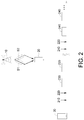
  • FIG. 2 it shows a schematic diagram according to the exemplary embodiment 2 of this disclosure.
  • the base station 10 has a plurality of beams, and herein two beams B 1 and B 2 are taken as an example for description, but not to limit this disclosure.
  • the base station 10 periodically transmits two downlink reference signals 210 and 220 , respectively, to the user equipment 20 through the beams B 1 and B 2 .
  • the base station 10 pre-configures the resources 230 and 240 to the user equipment 20 , wherein the resources 230 and 240 are related to beams B 1 and B 2 , respectively.
  • the user equipment 20 After the user equipment 20 receives the downlink reference signals 210 and 220 , the user equipment 20 can perform channel measurement to decide which channel currently has a better channel quality among the two channels corresponding to the downlink reference signals 210 and 220 , respectively. Herein, assuming that the channel corresponding to the downlink reference signal 210 has a better channel quality, the user equipment 20 can perform the grant-free uplink transmission through the resource 230 .
  • the user equipment 20 can perform the grant-free uplink transmission through the resource 240 .
  • FIG. 3 shows a flow chart of the grant-free uplink transmission according to the exemplary embodiment 2-1 of this disclosure.
  • the base station 10 transmits the grant-free configuration parameter to the user equipment 20 .
  • step 320 the base station 10 transmits the downlink reference signal 210 to the user equipment 20 through the beam B 1 .
  • the base station 10 transmits the downlink reference signal 220 to the user equipment 20 through the beam B 2 .
  • the beams B 1 and B 2 correspond to respective one of a plurality of uplink transmission resources assigned to the user equipment.
  • step 340 the user equipment 20 performs a channel measurement based on the received downlink reference signals 210 and 220 .
  • step 350 the user equipment 20 reports a channel measurement result to the base station 10 .
  • the base station 10 transmits a reference signal index control signaling to the user equipment 20 based on the channel measurement result reported by the user equipment 20 . That is, the base station 10 indicates the user equipment 20 about which channel has a better channel quality among the two channels corresponding to the downlink reference signals 210 and 220 , respectively.
  • the reference signal index control signaling comprises a reference signal index, and the reference signal index is related to the reference signal. It should be noted that the reference signal index control signaling may comprise one or more reference signal index, and the reference signal index can be an identifier of the downlink reference signal or an encoded code of the downlink reference signal.
  • the user equipment 20 receives the reference signal index control signaling responding to the reported channel measurement result, and the user equipment 20 decides an uplink beamforming weight or a precoder based on the downlink reference signal assigned by the reference signal index control signaling, and the user equipment 20 chooses one among the resources 230 or 240 based on the resource corresponding to the reference signal indicated by the reference signal index control signaling to use for the grant-free uplink transmission.
  • the user equipment 20 receives the reference signal index control signaling from the base station 10 after reporting the channel measurement result, and then decides the uplink beamforming weight or the precoder.
  • step 380 the user equipment 20 performs the grant-free uplink transmission through the resources 230 or 240 (assigned by the reference signal index control signaling).
  • FIG. 4 shows a flow chart of the grant-free uplink transmission according to the exemplary embodiment 2-2 of this disclosure.
  • the base station 10 transmits the grant-free configuration parameter to the user equipment 20 .
  • step 420 the base station 10 transmits the downlink reference signal 210 to the user equipment 20 through the beam B 1 .
  • step 430 the base station 10 transmits the downlink reference signal 220 to the user equipment 20 through the beam B 2 .
  • step 440 the user equipment 20 performs a channel measurement based on the received downlink reference signals 210 and 220 .
  • step 450 the user equipment 20 decides to choose one among the downlink reference signals 210 and 220 based on the channel measurement signal (i.e., the user equipment 20 decides which channel has a better channel quality based on the channel measurement result), that is, in this embodiment, the user equipment 20 do not have to report channel measurement result to the base station 10 .
  • step 460 the user equipment 20 decides an uplink beamforming weight or a precoder based on the chosen downlink reference signal.
  • step 470 the user equipment 20 performs the grant-free uplink transmission based on the chosen downlink reference signals 210 or 220 and through the resources 230 or 240 (related to the chosen downlink reference signal).
  • the exemplary embodiment 2-1 and the exemplary embodiment 2-2 are the sub-embodiments of the exemplary embodiment 2.
  • the exemplary embodiment 2, the exemplary embodiment 2-1, and the exemplary embodiment 2-2 of this disclosure can be implemented together with the exemplary embodiment 1 of this disclosure.
  • the exemplary embodiment 2-1, and the exemplary embodiment 2-2 of this disclosure because of choosing the better resource among the configured multiple resources based on the reference signal quality (i.e., channel quality) to perform the grant-free uplink transmission, the transmission reliability can be increased.
  • the reference signal quality i.e., channel quality
  • the base station 10 and/or the user equipment 20 can decide the code rate based on the number of transmission repetitions within a transmission period, the details will be described as following. Or to say, in exemplary embodiment 3 of this disclosure, deciding the number of transmission repetitions and/or a resource usage and/or a data quantity per transmission by the transmission occasion within the transmission period (for example but not limited to the uplink data ready time within the transmission period).
  • the data quantity per transmission is a constant value
  • the resource usage is a constant value.
  • FIG. 5 shows a flow chart of the grant-free uplink transmission according to the exemplary embodiment 3 of this disclosure.
  • the base station 10 transmits the grant-free configuration parameter to the user equipment 20 .
  • step 520 the base station 10 transmits a downlink reference signal to the user equipment 20 .
  • step 530 the user equipment 20 performs a channel measurement based on the downlink reference signal.
  • step 540 the user equipment 20 decides an uplink beamforming weight or a precoder based on the downlink reference signal.
  • the user equipment 20 decides the number of transmission repetitions and/or the resource usage and/or the data quantity per transmission based on the transmission occasion within the transmission period.
  • the data quantity per transmission is a constant value
  • the resource usage is a constant value.
  • step 560 the user equipment 20 performs the grant-free uplink transmission.
  • Exemplary embodiment 3-1A elastic physical resource block size (PRBS), fixed transport block size (TBS)
  • the user equipment 20 can decide PRBS based on the number of transmission repetitions within a transmission period (but TBS is fixed).
  • FIG. 6 it shows a schematic diagram according to the exemplary embodiment 3-1A of this disclosure.
  • RV redundancy version
  • the original data is 100 bits, and after the coding, the data is coded to 300 bits (for example but not limited to copying 3 or other copies of the original data).
  • the uplink data of the user equipment 20 is ready before the first transmission occasion (in FIG. 6 , the upward arrow represents that the uplink data is ready), then there can be 4 transmission repetitions within the transmission period.
  • the uplink data of the user equipment 20 is ready before the second transmission occasion, then there can be 3 transmission repetitions within the transmission period.
  • the uplink data of the user equipment 20 is ready before the third transmission occasion, then there can be 2 transmission repetitions within the transmission period.
  • the uplink data of the user equipment 20 is ready before the fourth (i.e., the last) transmission occasion, then there can be 1 transmission repetition within the transmission period.
  • TBS is fixed
  • exemplary embodiment 3-1A of this disclosure within a transmission period, if there are more transmission repetitions, then fewer resource is used for transmission per transmission repetition (i.e., PRBS is smaller, but TBS is fixed). In contrast, within a transmission period, if there are fewer transmission repetitions, then more resources are used to transmit per transmission repetition (i.e., PRBS is higher, but TBS is fixed). Therefore, the transmission efficiency can be effectively increased.
  • Exemplary embodiment 3-1B elastic physical resource block size (PRBS), fixed transport block size (TBS)
  • the uplink data of the user equipment 20 is ready before the first transmission occasion, then there can be 4 transmission repetitions within the transmission period.
  • the uplink data of the user equipment 20 is ready before the third transmission occasion, then there can be 2 transmission repetitions within the transmission period.
  • exemplary embodiment 3-1B of this disclosure within a transmission period, if there are more transmission repetitions, then fewer resource is used to transmit per transmission repetition (i.e., PRBS is smaller, but TBS is fixed). In contrast, within a transmission period, if there are fewer transmission repetitions, then more resources are used to transmit per transmission repetition (i.e., PRBS is higher, but TBS is fixed). Therefore, the transmission efficiency can be effectively increased.
  • Exemplary embodiment 3-1C elastic transport block size (TBS), fixed physical resource block size (PRBS)
  • the transmission data quantity TBS can be decided based on the transmission occasion within a transmission period (but the resource usage PRBS used each time is fixed).
  • the uplink data of the user equipment 20 is ready before the second transmission occasion, then there can be 3 transmission repetitions within the transmission period.
  • the uplink data of the user equipment 20 is ready before the third transmission occasion, then there can be 2 transmission repetitions within the transmission period.
  • the uplink data of the user equipment 20 is ready before the fourth (i.e., the last) transmission occasion, then there can be 1 transmission repetition within the transmission period.
  • PRBS PRBS is fixed, for example, using all of the resources.
  • Exemplary embodiment 3-1D elastic physical resource block size (PRBS) and/or fixed transport block size (TBS)
  • PRBS and/or TBS are decided based on the transmission occasion within a transmission period.
  • the uplink data of the user equipment 20 is ready before the second transmission occasion, then there can be 3 transmission repetitions within the transmission period.
  • the uplink data of the user equipment 20 is ready before the third transmission occasion, then there can be 2 transmission repetitions within the transmission period.
  • the uplink data of the user equipment 20 is ready before the fourth (i.e., the last) transmission occasion, then there can be 1 transmission repetition within the transmission period.
  • the data quantity transmitted each time and/or the resources used each time are decided based on the number of transmission repetitions. Therefore, the transmission efficiency can be effectively increased.
  • the base station 10 can further detect the start of the initial uplink transmission based on the energy detection result and/or the different start transmission with different demodulation reference signal (DMRS).
  • DMRS demodulation reference signal
  • the user equipment 20 can perform re-transmission based on the ACK/NACK signal returned by the base station 10 .
  • the number of transmission repetitions within a transmission period is decided based on the data quantity to be transmitted (herein refers to the data quantity before coding) which is ready by the user equipment.
  • the uplink data of the user equipment 20 is ready before the first transmission occasion. If the data quantity to be transmitted is bigger, then the transmission repetitions will be performed more times within the transmission period. If the data quantity to be transmitted is smaller, then the transmission repetitions will be performed fewer times within the transmission period.
  • the data to be transmitted of the user equipment 20 decreases from the maximum to the minimum, and within the transmission period, the number of transmission repetitions is 4, 3, 2, and 1, respectively.
  • the number of transmission repetitions within a transmission period is decided based on the data quantity to be transmitted (herein refers to the data quantity before coding) which is ready by the user equipment and/or the initial time of the first uplink transmission within a transmission period.
  • the transmission repetitions will be performed more times within the transmission period. If the data quantity to be transmitted is smaller, then the transmission repetitions will be performed fewer times within the transmission period.
  • the data to be transmitted of the user equipment 20 decreases from the maximum to the minimum, and within the transmission period, the number of transmission repetitions is 3, 2, and 1, respectively.
  • the user equipment 20 can decide the number of transmission repetitions within a transmission period based on the uplink transmission data quantity.
  • the user equipment can decide the data quantity of each transmission (i.e., dynamically decide TBS) based on the measurement result of the reference signal (or based on the (downlink) channel quality). Wherein deciding new TBS can be performed after the user equipment 20 decides the beamforming weight or the precoder, and after deciding new TBS, the user equipment 20 will starts to perform the grant-free uplink transmission.
  • n1 ⁇ n2 ⁇ n3 ⁇ n4, and n1-n4 is pre-configured by the base station 10 , and ⁇ 1- ⁇ 4 (i.e., refer to as difference value) is dynamically decided by the user equipment 20 based on the channel quality.
  • FIG. 13 shows a schematic diagram of the timeslot according to the exemplary embodiment 3-3 of this disclosure.
  • the timeslot may comprise a plurality of packet, wherein the sequence of the packets is: control information (for example but not limited to the demodulation reference signal (DMRS)), new TBS related information ((n1+ ⁇ 1) ⁇ (n4+ ⁇ 4) as described above), and the data to be transmitted.
  • control information for example but not limited to the demodulation reference signal (DMRS)
  • DMRS demodulation reference signal
  • new TBS related information ((n1+ ⁇ 1) ⁇ (n4+ ⁇ 4) as described above)
  • the user equipment 20 can report new TBS value to the base station 10 .
  • the resource (PRBS) used in each transmission can be varied.
  • the user equipment 20 can also report the periodicity of the uplink transmission period to the base station 10 .
  • at least one periodicity of the uplink transmission period is pre-configured by the base station 10 , and each periodicity of the uplink transmission period can be decided based on an index.
  • the exemplary embodiment 3-1A to the exemplary embodiment 3-1D, the exemplary embodiment 3-2A to the exemplary embodiment 3-2B, and the exemplary embodiment 3-3 are the sub-embodiments of the exemplary embodiment 3.
  • the exemplary embodiment 3 of this disclosure can be implemented together with the exemplary embodiment 1 of this disclosure, or the exemplary embodiment 3 of this disclosure can be implemented alone (does not have to be implemented together with the exemplary embodiment 1 of this disclosure).
  • the user equipment 20 decides 4 respective beamforming weights or 4 respective precoders.
  • the user equipment 20 transmits 4 uplink reference signals to the base station 10 through the 4 channels, respectively, based on the decided respective beamforming weight or precoder.
  • the base station 10 measures the uplink reference signal to estimate the 4 channels, and decides which one or more channel is better based on the channel estimation result. After that, the base station 10 transmits the reference signal index control signaling to the user equipment 20 , to indicate that which one or more channel is decided by the base station.
  • Each uplink reference signal is transmitted through the respective channel, and each uplink reference signal has a respective identifier. Therefore, the one or more channel decided by the base station 10 based on the channel estimation can be corresponded to the specific one or more uplink reference signal.
  • the reference signal index control signaling comprises the identifier of the uplink reference signal, and based on the corresponding relationship between the uplink reference signal and the channel, the user equipment is indicated by the identifier of the uplink reference signal.
  • the base station can encode the uplink reference signal, and in this case, the reference signal index control signaling comprises the encoded code of the uplink reference signal.
  • the user equipment 20 In response to the transmission of the uplink reference signal, the user equipment 20 receives the reference signal index control signaling, and chooses one or more from the 4 respective beamforming weights or the 4 respective precoders based on the reference signal index control signaling. In other words, after the user equipment 20 transmits the uplink reference signal, the user equipment 20 can receive the reference signal index control signaling from the base station 10 . After that, the user equipment 20 can perform the grant-free uplink transmission based on the chosen beamforming weight or precoder and through the channel indicated by the reference signal index control signaling.
  • the user equipment decides the beamforming weight or precoder based on the downlink reference signal transmitted by the base station 10 .
  • the user equipment also can decide the beamforming weight or precoder based on the uplink reference signal.
  • the user equipment also can decide the beamforming weight or precoder based on the uplink reference signal and the downlink reference signal. This is also within the spiritual range of this disclosure.
  • FIG. 14 discloses a functional block diagram of the user equipment according to the exemplary embodiment of this disclosure.
  • the user equipment 20 comprises: a controller 1410 and a wireless communication module 1420 .
  • the wireless communication module 1420 is coupled to the controller 1410 .
  • the wireless communication module 1420 can wirelessly communicate with the base station.
  • the controller 1410 controls the user equipment 20 to perform the grant-free uplink transmission of the above embodiments, and the details are not repeated herein.

Landscapes

  • Engineering & Computer Science (AREA)
  • Signal Processing (AREA)
  • Computer Networks & Wireless Communication (AREA)
  • Quality & Reliability (AREA)
  • Mobile Radio Communication Systems (AREA)

Abstract

Provided is a method of grant-free uplink transmission for a user equipment. The user equipment receives a grant-free configuration parameter. The user equipment receives at least one reference signal. The user equipment performs channel measurement based on the at least one reference signal. The user equipment decides at least one uplink beamforming weight or at least one precoder based on the at least one reference signal. The user equipment performs grant-free uplink transmission based on the decided at least one uplink beamforming weight or the at least one precoder and the grant-free configuration parameter.

Description

This application claims the benefit of U.S. provisional application Ser. No. 62/674,069, filed May 21, 2018. The disclosure of which is incorporated by reference herein in its entirety.
TECHNICAL FIELD
The technical field relates to a user equipment and a method of grant-free uplink transmission.
BACKGROUND
The fifth generation (referred to as 5G) mobile communication system is one of the current development directions of the wireless communication. The considerations of the 5G system comprises: low latency and high reliability.
The main challenge of the 5G system is how to improve the transmission rate. If the grant uplink transmission of the 4G system is continued to be used in the 5G system, then a large amount of control signaling is needed, and thus is unable to meet the low latency and high reliability required by the 5G system.
Therefore, how to meet the low latency and high reliability required by the 5G system is one of the directions of the industry.
SUMMARY
According to an exemplary embodiment of the disclosure, provided is a method of grant-free uplink transmission for a user equipment. The method includes: receiving a grant-free configuration parameter by the user equipment; receiving at least one reference signal by the user equipment; performing channel measurement based on the at least one reference signal by the user equipment; deciding at least one uplink beamforming weight or at least one precoder based on the at least one reference signal by the user equipment; and performing grant-free uplink transmission based on the decided at least one uplink beamforming weight or the at least one precoder and the grant-free configuration parameter by the user equipment.
According to another exemplary embodiment of the disclosure, provided is a method of grant-free uplink transmission for a user equipment. The method includes: deciding a number of transmission repetitions and/or a resource usage and/or a data quantity per transmission based on a transmission occasion within a transmission period by the user equipment; and performing grant-free uplink transmission based on the number of transmission repetitions and/or the resource usage and/or the data quantity per transmission by the user equipment.
According to another exemplary embodiment of the disclosure, provided is a user equipment. The user equipment comprises: a controller; and a wireless communication module coupled to the controller. The controller is configured to control: receiving a grant-free configuration parameter by the user equipment; receiving at least one reference signal by the user equipment; performing channel measurement based on the at least one reference signal by the user equipment; deciding at least one uplink beamforming weight or at least one precoder based on the at least one reference signal by the user equipment; and performing grant-free uplink transmission based on the decided at least one uplink beamforming weight or the at least one precoder and the grant-free configuration parameter by the user equipment.
According to another exemplary embodiment of the disclosure, provided is a user equipment. The user equipment comprises: a controller; and a wireless communication module coupled to the controller. The controller is configured to control: deciding a number of transmission repetitions and/or a resource usage and/or data quantity per transmission based on a transmission occasion within a transmission period by the user equipment; and performing grant-free uplink transmission based on the number of transmission repetitions and/or the resource usage and/or the data quantity per transmission by the user equipment.
In order to better understand the above and other aspects of the present invention, the accompanying drawings relate to the embodiments are described in the following:
BRIEF DESCRIPTION OF THE DRAWINGS
FIG. 1 shows a flow chart of the grant-free uplink transmission according to the exemplary embodiment 1 of this disclosure.
FIG. 2 shows a schematic diagram according to the exemplary embodiment 2 of this disclosure.
FIG. 3 shows a flow chart of the grant-free uplink transmission according to the exemplary embodiment 2-1 of this disclosure.
FIG. 4 shows a flow chart of the grant-free uplink transmission according to the exemplary embodiment 2-2 of this disclosure.
FIG. 5 shows a flow chart of the grant-free uplink transmission according to the exemplary embodiment 3 of this disclosure.
FIG. 6 shows a schematic diagram according to the exemplary embodiment 3-1A of this disclosure.
FIG. 7 shows a schematic diagram according to the exemplary embodiment 3-1B of this disclosure.
FIG. 8 shows a schematic diagram according to the exemplary embodiment 3-1C of this disclosure.
FIG. 9 shows a schematic diagram according to the exemplary embodiment 3-1D of this disclosure.
FIG. 10 shows a schematic diagram according to the exemplary embodiment 3-2A of this disclosure.
FIG. 11 shows a schematic diagram according to the exemplary embodiment 3-2B of this disclosure.
FIG. 12 shows a schematic diagram according to the exemplary embodiment 3-3 of this disclosure.
FIG. 13 shows a schematic diagram of the timeslot according to the exemplary embodiment 3-3 of this disclosure.
FIG. 14 discloses a functional block diagram of the user equipment according to the exemplary embodiment of this disclosure.
DESCRIPTION OF THE EMBODIMENTS
Technical terms of the disclosure are based on general definition in the technical field of the disclosure. If the disclosure describes or explains one or some terms, definition of the terms is based on the description or explanation of the disclosure. Each of the disclosed embodiments has one or more technical features. In possible implementation, one skilled person in the art would selectively implement part or all technical features of any embodiment of the disclosure or selectively combine part or all technical features of the embodiments of the disclosure.
A grant-free uplink transmission means that: the base station is pre-configured with uplink related resources, and the user equipment (for example but no limited to smart phones) performs the uplink transmission based on the pre-configured resources of the base station. In this way, the base station does not need to send an additional downlink control signal to the user equipment, so the signaling cost can be reduced.
Exemplary Embodiment 1
FIG. 1 shows a flow chart of the grant-free uplink transmission according to the exemplary embodiment 1 of this disclosure. As shown in FIG. 1, in step 110, a base station (BS) 10 transmits a grant-free configuration parameter to a user equipment (UE) 20. Herein, the grant-free configuration parameter, for example but not limited to, comprises any combination of the following parameters: the code rate, the modulation order, the transport block size (TBS), the physical resource block size (PRBS), the configured resources, the downlink reference signal (DL RS) related configuration, the uplink reference signal (UL RS) related configuration, the number of rank, etc.
In addition, in exemplary embodiment 1, deciding the code rate, the modulation order, the transport block size, and the physical resource block size can based on any combination of the followings: the first uplink transmission occasion within a transmission period, a number of transmission repetitions within a transmission period, the redundancy version sequence, the repetition pattern and the configured uplink transmission resource.
In step 120, the base station 10 transmits an at least one downlink reference signal to the user equipment 20.
In step 130, the user equipment 20 performs a channel measurement based on the at least one downlink reference signal.
In step 140, the user equipment 20 decides at least one uplink beamforming weight or at least one precoder based on the downlink reference signal. It is possible to use more than two uplink beamforming weights or more than two precoders for each grant-free uplink transmission. The detailed decision of the user equipment 20 on the uplink beamforming weight or the precoder may not be specifically described herein. In addition, in exemplary embodiment 1 of this disclosure, transmission and receiption between the base station 10 and the user equipment 20 are in time division duplex (TDD) mode. In TDD mode, the uplink channel and the downlink channel are separated by the time domain. In TDD mode, the uplink channel and the downlink channel uses the same frequency, but the base station transmits signal to the user equipment in a certain time period, and the user equipment transmits signal to the base station in another time period. Therefore, TDD mode has a channel reciprocity (it means that the uplink channel and the downlink channel have a corresponding relationship, that is, the downlink channel state can reflect the uplink channel state). Thus, the user equipment 20 can decide the uplink beamforming weight or the precoder.
In step 150, the user equipment 20 performs the grant-free uplink transmission based on the decided at least one uplink beamforming weight or the at least one precoder, and the grant-free configuration parameter.
As above, in exemplary embodiment 1 of this disclosure, the uplink beamforming weight or the precoder are decided by the user equipment rather than by the base station. Therefore, in exemplary embodiment 1 of this disclosure, the signaling cost and latency can be further reduced, and thus the efficiency can be increased.
Exemplary Embodiment 2
Now referring to FIG. 2, it shows a schematic diagram according to the exemplary embodiment 2 of this disclosure. As shown in FIG. 2, the base station 10 has a plurality of beams, and herein two beams B1 and B2 are taken as an example for description, but not to limit this disclosure.
The base station 10 periodically transmits two downlink reference signals 210 and 220, respectively, to the user equipment 20 through the beams B1 and B2. In addition, the base station 10 pre-configures the resources 230 and 240 to the user equipment 20, wherein the resources 230 and 240 are related to beams B1 and B2, respectively.
After the user equipment 20 receives the downlink reference signals 210 and 220, the user equipment 20 can perform channel measurement to decide which channel currently has a better channel quality among the two channels corresponding to the downlink reference signals 210 and 220, respectively. Herein, assuming that the channel corresponding to the downlink reference signal 210 has a better channel quality, the user equipment 20 can perform the grant-free uplink transmission through the resource 230.
Assuming that after this, due to the change of the channel state, the channel corresponding to the downlink reference signal 220 has a better channel quality, the user equipment 20 can perform the grant-free uplink transmission through the resource 240.
Exemplary Embodiment 2-1
FIG. 3 shows a flow chart of the grant-free uplink transmission according to the exemplary embodiment 2-1 of this disclosure. As shown in FIG. 3, in step 310, the base station 10 transmits the grant-free configuration parameter to the user equipment 20.
In step 320, the base station 10 transmits the downlink reference signal 210 to the user equipment 20 through the beam B1.
In step 330, the base station 10 transmits the downlink reference signal 220 to the user equipment 20 through the beam B2. The beams B1 and B2 correspond to respective one of a plurality of uplink transmission resources assigned to the user equipment.
In step 340, the user equipment 20 performs a channel measurement based on the received downlink reference signals 210 and 220.
In step 350, the user equipment 20 reports a channel measurement result to the base station 10.
In step 360, the base station 10 transmits a reference signal index control signaling to the user equipment 20 based on the channel measurement result reported by the user equipment 20. That is, the base station 10 indicates the user equipment 20 about which channel has a better channel quality among the two channels corresponding to the downlink reference signals 210 and 220, respectively. The reference signal index control signaling comprises a reference signal index, and the reference signal index is related to the reference signal. It should be noted that the reference signal index control signaling may comprise one or more reference signal index, and the reference signal index can be an identifier of the downlink reference signal or an encoded code of the downlink reference signal.
In step 370, the user equipment 20 receives the reference signal index control signaling responding to the reported channel measurement result, and the user equipment 20 decides an uplink beamforming weight or a precoder based on the downlink reference signal assigned by the reference signal index control signaling, and the user equipment 20 chooses one among the resources 230 or 240 based on the resource corresponding to the reference signal indicated by the reference signal index control signaling to use for the grant-free uplink transmission. In other words, the user equipment 20 receives the reference signal index control signaling from the base station 10 after reporting the channel measurement result, and then decides the uplink beamforming weight or the precoder.
In step 380, the user equipment 20 performs the grant-free uplink transmission through the resources 230 or 240 (assigned by the reference signal index control signaling).
Exemplary Embodiment 2-2
FIG. 4 shows a flow chart of the grant-free uplink transmission according to the exemplary embodiment 2-2 of this disclosure. As shown in FIG. 4, in step 410, the base station 10 transmits the grant-free configuration parameter to the user equipment 20.
In step 420, the base station 10 transmits the downlink reference signal 210 to the user equipment 20 through the beam B1.
In step 430, the base station 10 transmits the downlink reference signal 220 to the user equipment 20 through the beam B2.
In step 440, the user equipment 20 performs a channel measurement based on the received downlink reference signals 210 and 220.
In step 450, the user equipment 20 decides to choose one among the downlink reference signals 210 and 220 based on the channel measurement signal (i.e., the user equipment 20 decides which channel has a better channel quality based on the channel measurement result), that is, in this embodiment, the user equipment 20 do not have to report channel measurement result to the base station 10.
In step 460, the user equipment 20 decides an uplink beamforming weight or a precoder based on the chosen downlink reference signal.
In step 470, the user equipment 20 performs the grant-free uplink transmission based on the chosen downlink reference signals 210 or 220 and through the resources 230 or 240 (related to the chosen downlink reference signal).
The exemplary embodiment 2-1 and the exemplary embodiment 2-2 are the sub-embodiments of the exemplary embodiment 2. The exemplary embodiment 2, the exemplary embodiment 2-1, and the exemplary embodiment 2-2 of this disclosure can be implemented together with the exemplary embodiment 1 of this disclosure.
As stated above, in exemplary embodiment 2, the exemplary embodiment 2-1, and the exemplary embodiment 2-2 of this disclosure, because of choosing the better resource among the configured multiple resources based on the reference signal quality (i.e., channel quality) to perform the grant-free uplink transmission, the transmission reliability can be increased.
Exemplary Embodiment 3
In exemplary embodiment 3 of this disclosure, to increase the transmission efficiency, when performing the grant-free uplink transmission, the base station 10 and/or the user equipment 20 can decide the code rate based on the number of transmission repetitions within a transmission period, the details will be described as following. Or to say, in exemplary embodiment 3 of this disclosure, deciding the number of transmission repetitions and/or a resource usage and/or a data quantity per transmission by the transmission occasion within the transmission period (for example but not limited to the uplink data ready time within the transmission period). In one embodiment the data quantity per transmission is a constant value, and in one embodiment the resource usage is a constant value. The details will be described as following.
FIG. 5 shows a flow chart of the grant-free uplink transmission according to the exemplary embodiment 3 of this disclosure. As shown in FIG. 5, in step 510, the base station 10 transmits the grant-free configuration parameter to the user equipment 20.
In step 520, the base station 10 transmits a downlink reference signal to the user equipment 20.
In step 530, the user equipment 20 performs a channel measurement based on the downlink reference signal.
In step 540, the user equipment 20 decides an uplink beamforming weight or a precoder based on the downlink reference signal.
In step 550, the user equipment 20 decides the number of transmission repetitions and/or the resource usage and/or the data quantity per transmission based on the transmission occasion within the transmission period. In one embodiment the data quantity per transmission is a constant value, and in one embodiment the resource usage is a constant value.
In step 560, the user equipment 20 performs the grant-free uplink transmission.
Exemplary embodiment 3-1A: elastic physical resource block size (PRBS), fixed transport block size (TBS)
In exemplary embodiment 3-1A of this disclosure, the user equipment 20 can decide PRBS based on the number of transmission repetitions within a transmission period (but TBS is fixed). Now referring to FIG. 6, it shows a schematic diagram according to the exemplary embodiment 3-1A of this disclosure. As shown in FIG. 6, assume that within the transmission period, the upper limit of the number of transmission repetitions is 4, and the redundancy version (RV) sequence={0,0,0,0}. Assume that the original data is 100 bits, and after the coding, the data is coded to 300 bits (for example but not limited to copying 3 or other copies of the original data). RV=0 represents that the 1st bit to the 200th bit are transmitted; RV=1 represents that the 26th bit to the 225th bit are transmitted; RV=2 represents that the 51th bit to the 250th bit are transmitted; RV=3 represents that the 76th bit to the 275th bit are transmitted; and RV=4 represents that the 101th bit to the 300th bit are transmitted.
If the uplink data of the user equipment 20 is ready before the first transmission occasion (in FIG. 6, the upward arrow represents that the uplink data is ready), then there can be 4 transmission repetitions within the transmission period. In each transmission repetition, the user equipment 20 performs transmission with an uplink transmission of PRBS=m1 (m1 for example is 3), and the same amount of data is transmitted each time (i.e., TBS is fixed).
Similarly, if the uplink data of the user equipment 20 is ready before the second transmission occasion, then there can be 3 transmission repetitions within the transmission period. In each transmission repetition, the user equipment 20 performs transmission with an uplink transmission of PRBS=m2 (m2 for example is 4), and the same amount of data is transmitted each time (i.e., TBS is fixed).
Similarly, if the uplink data of the user equipment 20 is ready before the third transmission occasion, then there can be 2 transmission repetitions within the transmission period. In each transmission repetition, the user equipment 20 performs transmission with an uplink transmission of PRBS=m3 (m3 for example is 6), and the same amount of data is transmitted each time (i.e., TBS is fixed).
Similarly, if the uplink data of the user equipment 20 is ready before the fourth (i.e., the last) transmission occasion, then there can be 1 transmission repetition within the transmission period. In each transmission repetition, the user equipment 20 performs transmission with an uplink transmission of PRBS=m4 (m4 for example is 12), and the same amount of data is transmitted each time (i.e., TBS is fixed). In the above description, m1≤m2≤m3≤m4.
That is, in exemplary embodiment 3-1A of this disclosure, within a transmission period, if there are more transmission repetitions, then fewer resource is used for transmission per transmission repetition (i.e., PRBS is smaller, but TBS is fixed). In contrast, within a transmission period, if there are fewer transmission repetitions, then more resources are used to transmit per transmission repetition (i.e., PRBS is higher, but TBS is fixed). Therefore, the transmission efficiency can be effectively increased.
Exemplary embodiment 3-1B: elastic physical resource block size (PRBS), fixed transport block size (TBS)
In exemplary embodiment 3-1 B of this disclosure, PRBS is decided based on the transmission occasion within a transmission period (but TBS is fixed). FIG. 7 shows a schematic diagram according to the exemplary embodiment 3-1 B of this disclosure. The situation in FIG. 7 is similar to FIG. 6, and the difference is that in FIG. 7, the redundancy version sequence={0,3,0,3}.
If the uplink data of the user equipment 20 is ready before the first transmission occasion, then there can be 4 transmission repetitions within the transmission period. In each transmission repetition, the user equipment 20 performs transmission with an uplink transmission of PRBS=m1 (m1 for example is 3), and the same amount of data is transmitted each time (i.e., TBS is fixed).
Similarly, if the uplink data of the user equipment 20 is ready before the third transmission occasion, then there can be 2 transmission repetitions within the transmission period. In each transmission repetition, the user equipment 20 performs transmission with an uplink transmission of PRBS=m3 (m3 for example is 6), and the same amount of data is transmitted each time (i.e., TBS is fixed).
That is, in exemplary embodiment 3-1B of this disclosure, within a transmission period, if there are more transmission repetitions, then fewer resource is used to transmit per transmission repetition (i.e., PRBS is smaller, but TBS is fixed). In contrast, within a transmission period, if there are fewer transmission repetitions, then more resources are used to transmit per transmission repetition (i.e., PRBS is higher, but TBS is fixed). Therefore, the transmission efficiency can be effectively increased.
Exemplary embodiment 3-1C: elastic transport block size (TBS), fixed physical resource block size (PRBS)
In exemplary embodiment 3-1C of this disclosure, the transmission data quantity TBS can be decided based on the transmission occasion within a transmission period (but the resource usage PRBS used each time is fixed). Now referring to FIG. 8, it shows a schematic diagram according to the exemplary embodiment 3-1C of this disclosure. As shown in FIG. 8, assuming that the redundancy version sequence={0,0,0,0}. If the uplink data of the user equipment 20 is ready before the first transmission occasion, then there can be 4 transmission repetitions within the transmission period. In each transmission repetition, the user equipment 20 performs transmission with transmission data quantity TBS=n1 (n1 for example is 120 bits), and the same amount of resource is used for transmission each time (i.e., PRBS is fixed, for example, using all of the resources).
Similarly, if the uplink data of the user equipment 20 is ready before the second transmission occasion, then there can be 3 transmission repetitions within the transmission period. In each transmission repetition, the user equipment 20 performs transmission with transmission data quantity TBS=n2 (n2 for example is 90 bits), and the same amount of resource is used for transmission each time (i.e., PRBS is fixed, for example, using all of the resources).
Similarly, if the uplink data of the user equipment 20 is ready before the third transmission occasion, then there can be 2 transmission repetitions within the transmission period. In each transmission repetition, the user equipment 20 performs transmission with transmission data quantity TBS=n3 (n3 for example is 60 bits), and the same amount of resource is used for transmission each time (i.e., PRBS is fixed, for example, using all of the resources).
Similarly, if the uplink data of the user equipment 20 is ready before the fourth (i.e., the last) transmission occasion, then there can be 1 transmission repetition within the transmission period. In each transmission repetition, the user equipment 20 performs transmission with transmission data quantity TBS=n4 (n4 for example is 30 bits), and the same amount of resource is used for transmission each time (i.e., PRBS is fixed, for example, using all of the resources). In the above description, n1≥n2≥n3≥n4.
That is, in exemplary embodiment 3-1C of this disclosure, within a transmission period, if there are more transmission repetitions, then the data quantity transmitted each time is more, but the same amount of resource is used for transmission per transmission repetition (i.e., TBS is bigger, but PRBS is fixed). In contrast, within a transmission period, if there are fewer transmission repetitions, then the data quantity transmitted each time is fewer, but the same amount of resource is used for transmission per transmission repetition (i.e., TBS is smaller, but PRBS is fixed). Therefore, the transmission efficiency can be effectively increased
Exemplary embodiment 3-1D: elastic physical resource block size (PRBS) and/or fixed transport block size (TBS)
In exemplary embodiment 3-1D of this disclosure, PRBS and/or TBS are decided based on the transmission occasion within a transmission period. Now referring to FIG. 9, it shows a schematic diagram according to the exemplary embodiment 3-1D of this disclosure. As shown in FIG. 9, assuming that the redundancy version sequence={0,0,0,0}. If the uplink data of the user equipment 20 is ready before the first transmission occasion, then there can be 4 transmission repetitions within the transmission period. In each transmission repetition, the user equipment 20 performs transmission with {TBS, PRBS}={n1, m1}.
Similarly, if the uplink data of the user equipment 20 is ready before the second transmission occasion, then there can be 3 transmission repetitions within the transmission period. In each transmission repetition, the user equipment 20 performs transmission with {TBS, PRBS}={n2, m2}.
Similarly, if the uplink data of the user equipment 20 is ready before the third transmission occasion, then there can be 2 transmission repetitions within the transmission period. In each transmission repetition, the user equipment 20 performs transmission with {TBS, PRBS}={n3, m3}.
Similarly, if the uplink data of the user equipment 20 is ready before the fourth (i.e., the last) transmission occasion, then there can be 1 transmission repetition within the transmission period. In each transmission repetition, the user equipment 20 performs transmission with {TBS, PRBS}={n4, m4}. In the above description, n1≥n2≥n3≥n4 and m1≤m2≤m3≤m4.
That is, in exemplary embodiment 3-1D of this disclosure, within a transmission period, the data quantity transmitted each time and/or the resources used each time are decided based on the number of transmission repetitions. Therefore, the transmission efficiency can be effectively increased.
In exemplary embodiment 3-1A to exemplary embodiment 3-1D, the base station 10 can further detect the start of the initial uplink transmission based on the energy detection result and/or the different start transmission with different demodulation reference signal (DMRS). In addition, if the initial uplink transmission failed, the user equipment 20 can perform re-transmission based on the ACK/NACK signal returned by the base station 10.
Exemplary Embodiment 3-2A
In exemplary embodiment 3-2A of this disclosure, the number of transmission repetitions within a transmission period is decided based on the data quantity to be transmitted (herein refers to the data quantity before coding) which is ready by the user equipment. Now referring to FIG. 10, it shows a schematic diagram according to the exemplary embodiment 3-2A of this disclosure. As shown in FIG. 10, assuming that the redundancy version sequence={0,0,0,0}. At below, as an example for description, the uplink data of the user equipment 20 is ready before the first transmission occasion. If the data quantity to be transmitted is bigger, then the transmission repetitions will be performed more times within the transmission period. If the data quantity to be transmitted is smaller, then the transmission repetitions will be performed fewer times within the transmission period.
In FIG. 10, from top to bottom, the data to be transmitted of the user equipment 20 decreases from the maximum to the minimum, and within the transmission period, the number of transmission repetitions is 4, 3, 2, and 1, respectively. In each transmission occasion repetition, the user equipment 20 performs transmission with TBS=n1, TBS=n2, TBS=n3, and TBS=n4, and n1≥n2≥n3≥n4. Therefore, the transmission efficiency can be effectively increased.
Exemplary Embodiment 3-2B
In exemplary embodiment 3-2B of this disclosure, the number of transmission repetitions within a transmission period is decided based on the data quantity to be transmitted (herein refers to the data quantity before coding) which is ready by the user equipment and/or the initial time of the first uplink transmission within a transmission period. Now referring to FIG. 11, it shows a schematic diagram according to the exemplary embodiment 3-2B of this disclosure. As shown in FIG. 11, assuming that the redundancy version sequence={0,0,0,0}. At below, as an example for description, the uplink data of the user equipment 20 is ready before the second transmission occasion.
If the data quantity to be transmitted is bigger, then the transmission repetitions will be performed more times within the transmission period. If the data quantity to be transmitted is smaller, then the transmission repetitions will be performed fewer times within the transmission period.
In FIG. 11, from top to bottom, the data to be transmitted of the user equipment 20 decreases from the maximum to the minimum, and within the transmission period, the number of transmission repetitions is 3, 2, and 1, respectively. In each transmission occasion repetition, the user equipment 20 performs transmission with TBS=n2, TBS=n3, and TBS=n4, and n2≥n3≥n4. Therefore, the transmission efficiency can be effectively increased.
In exemplary embodiment 3-2A and exemplary embodiment 3-2B, the user equipment 20 can decide the number of transmission repetitions within a transmission period based on the uplink transmission data quantity.
Exemplary Embodiment 3-3
In exemplary embodiment 3-3 of this disclosure, the user equipment can decide the data quantity of each transmission (i.e., dynamically decide TBS) based on the measurement result of the reference signal (or based on the (downlink) channel quality). Wherein deciding new TBS can be performed after the user equipment 20 decides the beamforming weight or the precoder, and after deciding new TBS, the user equipment 20 will starts to perform the grant-free uplink transmission. Now referring to FIG. 12, it shows a schematic diagram according to the exemplary embodiment 3-3 of this disclosure. As shown in FIG. 12, assuming that the redundancy version sequence={0,0,0,0}.
If the uplink data of the user equipment 20 is ready before the first transmission occasion, then there can be 4 transmission repetitions within the transmission period. In each transmission occasion repetition, the user equipment 20 decides the transmission data quantity TBS=n1+Δ1 (n1 for example is 120 bits, and Δ1 for example is 20 bits) based on the measurement result of the reference signal (or based on the (downlink) channel quality) to perform transmission, and the resources used in each transmission may be fixed or elastic (i.e., PRBS is fixed or elastic).
If the uplink data of the user equipment 20 is ready before the second transmission occasion, then there can be 3 transmission repetitions within the transmission period. In each transmission occasion repetition, the user equipment 20 decides the transmission data quantity TBS=n2+Δ2 (n2 for example is 90 bits, and Δ2 for example is 15 bits) based on the measurement result of the reference signal (or based on the (downlink) channel quality) to perform transmission, and the resources used in each transmission may be fixed or elastic (i.e., PRBS is fixed or elastic).
If the uplink data of the user equipment 20 is ready before the third transmission occasion, then there can be 2 transmission repetitions within the transmission period. In each transmission occasion repetition, the user equipment 20 decides the transmission data quantity TBS=n3+Δ3 (n3 for example is 60 bits, and Δ3 for example is 10 bits) based on the measurement result of the reference signal (or based on the (downlink) channel quality) to perform transmission, and the resources used in each transmission may be fixed or elastic (i.e., PRBS is fixed or elastic).
If the uplink data of the user equipment 20 is ready before the fourth transmission occasion, then there can be 1 transmission repetition within the transmission period. In each transmission occasion repetition, the user equipment 20 decides the transmission data quantity TBS=n4+Δ4 (n4 for example is 30 bits, and Δ4 for example is 5 bits) based on the measurement result of the reference signal (or based on the (downlink) channel quality) to perform transmission, and the resources used in each transmission may be fixed or elastic (i.e., PRBS is fixed or elastic).
In the above description, n1≥n2≥n3≥n4, and n1-n4 is pre-configured by the base station 10, and Δ1-Δ4 (i.e., refer to as difference value) is dynamically decided by the user equipment 20 based on the channel quality.
That is, in exemplary embodiment 3-3 of this disclosure, if the channel quality is better, then the data quantity transmitted by the user equipment each time can be more. Therefore, the transmission efficiency can be effectively increased.
FIG. 13 shows a schematic diagram of the timeslot according to the exemplary embodiment 3-3 of this disclosure. As shown in FIG. 13, the timeslot may comprise a plurality of packet, wherein the sequence of the packets is: control information (for example but not limited to the demodulation reference signal (DMRS)), new TBS related information ((n1+Δ1)−(n4+Δ4) as described above), and the data to be transmitted.
That is, in exemplary embodiment 3-3 of this disclosure, the user equipment 20 can report new TBS value to the base station 10. In addition, the resource (PRBS) used in each transmission can be varied. In addition, the user equipment 20 can also report the periodicity of the uplink transmission period to the base station 10. For example, at least one periodicity of the uplink transmission period is pre-configured by the base station 10, and each periodicity of the uplink transmission period can be decided based on an index.
The exemplary embodiment 3-1A to the exemplary embodiment 3-1D, the exemplary embodiment 3-2A to the exemplary embodiment 3-2B, and the exemplary embodiment 3-3 are the sub-embodiments of the exemplary embodiment 3. The exemplary embodiment 3 of this disclosure can be implemented together with the exemplary embodiment 1 of this disclosure, or the exemplary embodiment 3 of this disclosure can be implemented alone (does not have to be implemented together with the exemplary embodiment 1 of this disclosure).
In addition, in other possible embodiments of this disclosure, for example, there are a plurality of channels (for example but not limited to 4) between the base station 10 and the user equipment 20. After the user equipment 20 measures each channel, the user equipment 20 decides 4 respective beamforming weights or 4 respective precoders. The user equipment 20 transmits 4 uplink reference signals to the base station 10 through the 4 channels, respectively, based on the decided respective beamforming weight or precoder. The base station 10 measures the uplink reference signal to estimate the 4 channels, and decides which one or more channel is better based on the channel estimation result. After that, the base station 10 transmits the reference signal index control signaling to the user equipment 20, to indicate that which one or more channel is decided by the base station. Each uplink reference signal is transmitted through the respective channel, and each uplink reference signal has a respective identifier. Therefore, the one or more channel decided by the base station 10 based on the channel estimation can be corresponded to the specific one or more uplink reference signal. The reference signal index control signaling comprises the identifier of the uplink reference signal, and based on the corresponding relationship between the uplink reference signal and the channel, the user equipment is indicated by the identifier of the uplink reference signal. In other implementation, the base station can encode the uplink reference signal, and in this case, the reference signal index control signaling comprises the encoded code of the uplink reference signal.
In response to the transmission of the uplink reference signal, the user equipment 20 receives the reference signal index control signaling, and chooses one or more from the 4 respective beamforming weights or the 4 respective precoders based on the reference signal index control signaling. In other words, after the user equipment 20 transmits the uplink reference signal, the user equipment 20 can receive the reference signal index control signaling from the base station 10. After that, the user equipment 20 can perform the grant-free uplink transmission based on the chosen beamforming weight or precoder and through the channel indicated by the reference signal index control signaling.
In addition, in the above embodiments, the user equipment decides the beamforming weight or precoder based on the downlink reference signal transmitted by the base station 10. In other possible embodiments of this disclosure, the user equipment also can decide the beamforming weight or precoder based on the uplink reference signal. Or, in other possible embodiments of this disclosure, the user equipment also can decide the beamforming weight or precoder based on the uplink reference signal and the downlink reference signal. This is also within the spiritual range of this disclosure.
FIG. 14 discloses a functional block diagram of the user equipment according to the exemplary embodiment of this disclosure. As shown in FIG. 14, the user equipment 20 comprises: a controller 1410 and a wireless communication module 1420. The wireless communication module 1420 is coupled to the controller 1410. The wireless communication module 1420 can wirelessly communicate with the base station. The controller 1410 controls the user equipment 20 to perform the grant-free uplink transmission of the above embodiments, and the details are not repeated herein.
It will be apparent to those skilled in the art that various modifications and variations can be made to the disclosed embodiments. It is intended that the specification and examples be considered as exemplary only, with a true scope of the disclosure being indicated by the following claims and their equivalents.

Claims (42)

What is claimed is:
1. A method of grant-free uplink transmission for a user equipment, comprising:
receiving a grant-free configuration parameter by the user equipment;
receiving at least one reference signal by the user equipment;
performing channel measurement based on the at least one reference signal by the user equipment;
deciding at least one uplink beamforming weight or at least one precoder based on the at least one reference signal by the user equipment; and
performing grant-free uplink transmission based on the decided at least one uplink beamforming weight or the at least one precoder and the grant-free configuration parameter by the user equipment.
2. The method of claim 1, wherein the grant-free configuration parameter comprises any combination of the following parameters: a code rate, a modulation order, a transport block size, a physical resource block size, a configured resource, a downlink reference signal related configuration, an uplink reference signal related configuration, a number of rank.
3. The method of claim 2, wherein deciding the code rate, the modulation order, the transport block size, and the physical resource block size is based on any combination of the followings: a transmission occasion within a transmission period, a number of transmission repetitions within the transmission period, a redundancy version sequence, a repetition pattern and a configured uplink transmission resource.
4. The method of claim 1, wherein each of the at least one reference signal comprises any combination of the followings: an uplink reference signal and a downlink reference signal.
5. The method of claim 1, wherein,
the at least one reference signal corresponds to at least one uplink transmission resource;
the step of deciding the at least one uplink beamforming weight or the at least one precoder by the user equipment based on the at least one reference signal comprises:
receiving a reference signal index control signaling by the user equipment; and
deciding, by the user equipment, the at least one uplink beamforming weight or the at least one precoder based on the reference signal indicated by the reference signal index control signaling; and
the method further comprises:
choosing, by the user equipment, one among the at least one uplink transmission resource based on the reference signal indicated by the reference signal index control signaling, wherein the user equipment further performs grant-free uplink transmission based on the chosen at least one uplink transmission resource.
6. The method of claim 5, wherein,
the user equipment receives a plurality of reference signals, and the step of the user equipment performing channel measurement based on the plurality of reference signals comprises reporting a channel measurement result, and the step of deciding the at least one uplink beamforming weight or the at least one precoder by the user equipment based on the plurality of reference signals further comprises: in response to the reported channel measurement result, receiving the reference signal index control signaling by the user equipment.
7. The method of claim 6, wherein the user equipment wirelessly communicates with a base station, and the method further comprises:
transmitting the reference signal index control signaling by the base station to the user equipment based on the channel measurement result received from the user equipment.
8. The method of claim 1, wherein,
the at least one reference signal corresponds to at least one uplink transmission resource, and the method further comprises:
choosing one among the at least one reference signal by the user equipment based on a channel measurement result; and
choosing one among the at least one uplink transmission resource by the user equipment based on the chosen at least one reference signal to perform grant-free uplink transmission.
9. The method of claim 8, wherein the step of deciding the at least one uplink beamforming weight or the at least one precoder by the user equipment based on the at least one reference signal further comprises:
deciding the at least one uplink beamforming weight or the at least one precoder by the user equipment based on the chosen at least one reference signal.
10. The method of claim 8, wherein the user equipment wirelessly communicates with a base station, and the method further comprises:
transmitting a reference signal index control signaling by the base station to the user equipment based on the channel measurement result received from the user equipment.
11. The method of claim 1, wherein,
the user equipment receives a plurality of reference signals, and a plurality of channels are measured based on the plurality of reference signals, and the step of deciding the at least one uplink beamforming weight or the at least one precoder by the user equipment based on the at least one reference signal comprises:
deciding a plurality of uplink beamforming weights or a plurality of precoders by the user equipment based on a channel measurement result;
receiving a reference signal index control signaling by the user equipment; and
choosing one among the plurality of uplink beamforming weights or the plurality of precoders by the user equipment based on the reference signal index control signaling,
wherein the user equipment performs grant-free uplink transmission based on the chosen uplink beamforming weight or the chosen precoder.
12. The method of claim 11, wherein the step of deciding the at least one uplink beamforming weight or the at least one precoder by the user equipment based on the at least one reference signal further comprises:
transmitting, by the user equipment, a plurality of uplink reference signals through the plurality of channels, respectively, based on the decided at least one uplink beamforming weight or the at least one precoder, wherein in response to transmission of the plurality of uplink reference signals, the user equipment receives the reference signal index control signaling.
13. The method of claim 1, wherein,
the user equipment decides a number of transmission repetitions and/or a resource usage and/or a data quantity per transmission based on a transmission occasion within a transmission period to perform grant-free uplink transmission.
14. The method of claim 1, wherein the user equipment wirelessly communicates with a base station, and the method further comprises:
transmitting the grant-free configuration parameter and the at least one reference signal by the base station.
15. A method of grant-free uplink transmission for a user equipment, comprising:
deciding a number of transmission repetitions and/or a resource usage and/or a data quantity per transmission based on a transmission occasion within a transmission period by the user equipment; and
performing grant-free uplink transmission based on the number of transmission repetitions and/or the resource usage and/or the data quantity per transmission by the user equipment.
16. The method of claim 15, further comprising:
receiving a grant-free configuration parameter by the user equipment;
receiving at least one reference signal by the user equipment;
performing channel measurement based on the at least one reference signal by the user equipment; and
deciding at least one uplink beamforming weight or at least one precoder based on a channel measurement result by the user equipment,
wherein the user equipment performs grant-free uplink transmission based on the number of transmission repetitions and/or the resource usage and/or the data quantity per transmission and the at least one uplink beamforming weight or the at least one precoder.
17. The method of claim 15, wherein the data quantity per transmission is a constant value, and the user equipment decides the number of transmission repetitions and the resource usage based on the transmission occasion within the transmission period.
18. The method of claim 15, wherein the resource usage is a constant value, and the user equipment decides the number of transmission repetitions and the data quantity per transmission based on the transmission occasion within the transmission period.
19. The method of claim 15, wherein the user equipment decides the number of transmission repetitions, the resource usage, and the data quantity per transmission based on the transmission occasion within the transmission period.
20. The method of claim 15, wherein the user equipment further decides the number of transmission repetitions and the data quantity per transmission based on a data quantity to be transmitted.
21. The method of claim 15, wherein the user equipment further decides the data quantity per transmission based on a channel quality, and the user equipment reports the decided data quantity per transmission.
22. A user equipment, comprising:
a controller; and
a wireless communication module coupled to the controller, and the controller is configured to control:
receiving a grant-free configuration parameter by the user equipment;
receiving at least one reference signal by the user equipment;
performing channel measurement based on the at least one reference signal by the user equipment;
deciding at least one uplink beamforming weight or at least one precoder based on the at least one reference signal by the user equipment; and
performing grant-free uplink transmission based on the decided at least one uplink beamforming weight or the at least one precoder and the grant-free configuration parameter by the user equipment.
23. The user equipment of claim 22, wherein the grant-free configuration parameter comprises any combination of the following parameters: a code rate, a modulation order, a transport block size, a physical resource block size, a configured resource, a downlink reference signal related configuration, an uplink reference signal related configuration, a number of rank.
24. The user equipment of claim 22, wherein deciding the code rate, the modulation order, the transport block size, and the physical resource block size is based on any combination of the followings: a transmission occasion within a transmission period, a number of transmission repetitions within the transmission period, a redundancy version sequence, a repetition pattern and a configured uplink transmission resource.
25. The user equipment of claim 22, wherein each of the at least one reference signal comprises any combination of the followings: an uplink reference signal and a downlink reference signal.
26. The user equipment of claim 22, wherein,
the controller is configured to control:
corresponding the at least one reference signal to at least one uplink transmission resource;
when the user equipment decides the at least one uplink beamforming weight or the at least one precoder based on the at least one reference signal,
the user equipment receives a reference signal index control signaling; and
the user equipment decides the at least one uplink beamforming weight or the at least one precoder based on the at least one reference signal indicated by the reference signal index control signaling; and
the user equipment chooses one among the at least one uplink transmission resource based on the at least one reference signal indicated by the reference signal index control signaling, wherein the user equipment further performs grant-free uplink transmission based on the chosen at least one uplink transmission resource.
27. The user equipment of claim 26, wherein,
the controller is configured to control:
receiving the at least one reference signal by the user equipment, and performing channel measurement by the user equipment based on the at least one reference signal, and reporting a channel measurement result; and
when the user equipment decides the at least one uplink beamforming weight or the at least one precoder based on the at least one reference signal, in response to the reported channel measurement result, the user equipment receives the reference signal index control signaling.
28. The user equipment of claim 27, wherein the user equipment wirelessly communicates with a base station, the base station transmits the reference signal index control signaling to the user equipment based on the channel measurement result received from the user equipment.
29. The user equipment of claim 22, wherein,
the controller is configured to control:
corresponding the at least one reference signal to at least one uplink transmission resource;
choosing one among the at least one reference signal by the user equipment based on a channel measurement result; and
choosing one among the at least one uplink transmission resource by the user equipment based on the chosen at least one reference signal to perform grant-free uplink transmission.
30. The user equipment of claim 29, wherein when the user equipment decides the at least one uplink beamforming weight or the at least one precoder based on the at least one reference signal, the user equipment decides the at least one uplink beamforming weight or the at least one precoder based on the chosen at least one reference signal.
31. The user equipment of claim 29, wherein the user equipment wirelessly communicates with a base station, the base station transmits a reference signal index control signaling to the user equipment based on the channel measurement result received from the user equipment.
32. The user equipment of claim 22, wherein the controller is configured to control:
receiving the at least one reference signal by the user equipment, and measuring a plurality of channels based on the at least one reference signal by the user equipment,
when the user equipment decides the at least one uplink beamforming weight or the at least one precoder based on the at least one reference signal,
the user equipment decides the at least one uplink beamforming weight or the at least one precoder based on a channel measurement result;
the user equipment receives a reference signal index control signaling; and
the user equipment chooses one among the at least one uplink beamforming weight or the at least one precoder based on the reference signal index control signaling;
wherein the user equipment performs grant-free uplink transmission based on the chosen at least one uplink beamforming weight or the at least one precoder.
33. The user equipment of claim 32, wherein,
the controller is configured to control:
when the user equipment decides the at least one uplink beamforming weight or the at least one precoder based on the at least one reference signal, the user equipment transmits a plurality of uplink reference signals through the plurality of channels, respectively, based on the decided at least one uplink beamforming weight or the at least one precoder, wherein in response to transmission of the plurality of uplink reference signals, the user equipment receives the reference signal index control signaling.
34. The user equipment of claim 22, wherein,
the user equipment decides a number of transmission repetitions and/or a resource usage and/or a data quantity per transmission based on a transmission occasion within a transmission period.
35. The user equipment of claim 22, wherein the user equipment wirelessly communicates with a base station, and the base station transmits the grant-free configuration parameter and the at least one reference signal.
36. A user equipment, comprising:
a controller; and
a wireless communication module coupled to the controller, and the controller is configured to control:
deciding a number of transmission repetitions and/or a resource usage and/or a data quantity per transmission based on a transmission occasion within a transmission period by the user equipment; and
performing grant-free uplink transmission based on the number of transmission repetitions and/or the resource usage and/or the data quantity per transmission by the user equipment.
37. The user equipment of claim 36, wherein the controller controls:
receiving a grant-free configuration parameter by the user equipment;
receiving at least one reference signal by the user equipment;
performing channel measurement by the user equipment based on the at least one reference signal; and
deciding at least one uplink beamforming weight or at least one precoder by the user equipment based on a channel measurement result,
wherein the user equipment performs grant-free uplink transmission based on the number of transmission repetitions and/or the resource usage and/or the data quantity per transmission and the at least one uplink beamforming weight or the at least one precoder.
38. The user equipment of claim 36, wherein the data quantity per transmission is a constant value, and the controller controls the user equipment to decide the number of transmission repetitions and the resource usage based on the transmission occasion within the transmission period.
39. The user equipment of claim 36, wherein the resource usage is a constant value, and the controller controls the user equipment to decide the number of transmission repetitions and the data quantity per transmission based on the transmission occasion within the transmission period.
40. The user equipment of claim 36, wherein the controller controls the user equipment to decide the number of transmission repetitions, the resource usage, and the data quantity per transmission based on the transmission occasion within the transmission period.
41. The user equipment of claim 36, wherein the controller controls the user equipment to further decide the number of transmission repetitions and the data quantity per transmission based on a data quantity to be transmitted.
42. The user equipment of claim 36, wherein the controller controls the user equipment to further decide the data quantity per transmission based on a channel quality, and the user equipment reports the decided data quantity per transmission.
US16/418,288 2018-05-21 2019-05-21 User equipment and method for grant-free uplink transmission Active 2039-10-14 US10931349B2 (en)

Priority Applications (1)

Application Number Priority Date Filing Date Title
US16/418,288 US10931349B2 (en) 2018-05-21 2019-05-21 User equipment and method for grant-free uplink transmission

Applications Claiming Priority (2)

Application Number Priority Date Filing Date Title
US201862674069P 2018-05-21 2018-05-21
US16/418,288 US10931349B2 (en) 2018-05-21 2019-05-21 User equipment and method for grant-free uplink transmission

Publications (2)

Publication Number Publication Date
US20190372639A1 US20190372639A1 (en) 2019-12-05
US10931349B2 true US10931349B2 (en) 2021-02-23

Family

ID=68623466

Family Applications (1)

Application Number Title Priority Date Filing Date
US16/418,288 Active 2039-10-14 US10931349B2 (en) 2018-05-21 2019-05-21 User equipment and method for grant-free uplink transmission

Country Status (3)

Country Link
US (1) US10931349B2 (en)
CN (1) CN110519846B (en)
TW (1) TWI736893B (en)

Families Citing this family (5)

* Cited by examiner, † Cited by third party
Publication number Priority date Publication date Assignee Title
WO2021228394A1 (en) 2020-05-14 2021-11-18 Nokia Technologies Oy Coupled downlink and uplink reference signals for efficient multi-rtt positioning
US11838920B2 (en) * 2020-07-30 2023-12-05 Qualcomm Incorporated Beam-based configured grant—small data transfer occasions
KR20240015619A (en) 2021-05-31 2024-02-05 삼성전자주식회사 Method performed by user equipment and user equipment
US20240372669A1 (en) * 2021-08-23 2024-11-07 Telefonaktiebolaget Lm Ericsson (Publ) Uplink transmission with extended uplink reference signal resources
CN116321481B (en) * 2022-09-06 2025-10-17 中信科移动通信技术股份有限公司 Uplink scheduling-free transmission method, device and storage medium

Citations (18)

* Cited by examiner, † Cited by third party
Publication number Priority date Publication date Assignee Title
US8320341B2 (en) 2007-10-23 2012-11-27 Nokia Corporation Re-transmission capability in semi-persistent transmission
US20130003788A1 (en) 2011-01-07 2013-01-03 Interdigital Patent Holdings, Inc. Communicating channel state information (csi) of multiple transmission points
US8634364B2 (en) 2010-04-20 2014-01-21 Qualcomm Incorporated Semi-persistent scheduling grants in heterogeneous networks
US8879454B2 (en) 2008-12-15 2014-11-04 Blackberry Limited Semi-persistent scheduling and discontinuous reception alignment
US20160219627A1 (en) 2015-01-27 2016-07-28 Kelvin Kar Kin Au System and method for transmission in a grant-free uplink transmission scheme
US9681430B2 (en) 2012-10-29 2017-06-13 Telefonaktiebolaget Lm Ericsson (Publ) Methods and arrangements for semi-persistent scheduling
TW201729572A (en) 2016-02-05 2017-08-16 廣東歐珀移動通信有限公司 Communication method, terminal device and network device
WO2018059173A1 (en) 2016-09-30 2018-04-05 华为技术有限公司 Unlicensed uplink information transmission method, network device, and terminal device
TWI621369B (en) 2015-08-06 2018-04-11 電信科學技術研究院 Method and equipment for data transmission
WO2018076956A1 (en) 2016-10-26 2018-05-03 华为技术有限公司 Grant-free transmission method, terminal device and network device
WO2018082414A1 (en) 2016-11-04 2018-05-11 华为技术有限公司 Unlicensed transmission method, terminal and network equipment
WO2018086541A1 (en) 2016-11-11 2018-05-17 Huawei Technologies Co., Ltd. Systems and methods for grant-free uplink transmission
US20180139774A1 (en) 2016-11-15 2018-05-17 Huawei Technologies Co., Ltd. Systems and methods for grant-free uplink transmissions
TW201836391A (en) 2017-03-20 2018-10-01 大陸商廣東歐珀移動通信有限公司 Method for data transmission, terminal equipment, and network equipment
US10141988B1 (en) * 2017-06-28 2018-11-27 Telefonaktiebolaget Lm Ericsson (Publ) Method and first radio node for communicating data using precoders
US10462796B2 (en) * 2017-02-06 2019-10-29 Telefonaktiebolaget Lm Ericsson (Publ) Systems and methods of reducing interference in a wireless communications system
US20200059960A1 (en) * 2017-05-01 2020-02-20 Sony Corporation Communication apparatus, base station apparatus, method, and recording medium
US20200146032A1 (en) * 2017-05-18 2020-05-07 Lg Electronics Inc. Method and apparatus for performing uplink transmission in a wireless communication system

Family Cites Families (6)

* Cited by examiner, † Cited by third party
Publication number Priority date Publication date Assignee Title
KR101839812B1 (en) * 2011-08-11 2018-03-19 삼성전자주식회사 Method and apparatus for mixed analog and digital beam forming
CN105743626B (en) * 2014-12-30 2020-09-15 北京三星通信技术研究有限公司 Method and equipment for receiving downlink channel and/or downlink reference signal
US10021573B2 (en) * 2015-04-13 2018-07-10 Industrial Technology Research Institute Method and device for uplink transmission by using unlicensed spectrum
CN109479322B (en) * 2016-07-13 2021-02-12 华为技术有限公司 Network node, user equipment and method for license-free data transmission
CN108024366A (en) * 2016-11-04 2018-05-11 北京三星通信技术研究有限公司 It is a kind of based on exempt from scheduling data transmission method and equipment
WO2018084559A1 (en) * 2016-11-04 2018-05-11 Samsung Electronics Co., Ltd. Method and apparatus for grant-free data transmission in wireless communication system

Patent Citations (21)

* Cited by examiner, † Cited by third party
Publication number Priority date Publication date Assignee Title
US8320341B2 (en) 2007-10-23 2012-11-27 Nokia Corporation Re-transmission capability in semi-persistent transmission
US8879454B2 (en) 2008-12-15 2014-11-04 Blackberry Limited Semi-persistent scheduling and discontinuous reception alignment
US8634364B2 (en) 2010-04-20 2014-01-21 Qualcomm Incorporated Semi-persistent scheduling grants in heterogeneous networks
US20130003788A1 (en) 2011-01-07 2013-01-03 Interdigital Patent Holdings, Inc. Communicating channel state information (csi) of multiple transmission points
US9681430B2 (en) 2012-10-29 2017-06-13 Telefonaktiebolaget Lm Ericsson (Publ) Methods and arrangements for semi-persistent scheduling
US20160219627A1 (en) 2015-01-27 2016-07-28 Kelvin Kar Kin Au System and method for transmission in a grant-free uplink transmission scheme
TWI621369B (en) 2015-08-06 2018-04-11 電信科學技術研究院 Method and equipment for data transmission
TW201729572A (en) 2016-02-05 2017-08-16 廣東歐珀移動通信有限公司 Communication method, terminal device and network device
WO2018059173A1 (en) 2016-09-30 2018-04-05 华为技术有限公司 Unlicensed uplink information transmission method, network device, and terminal device
CN107889231A (en) 2016-09-30 2018-04-06 华为技术有限公司 Exempt from method, the network equipment and the terminal device of transmission uplink information authorized
WO2018076956A1 (en) 2016-10-26 2018-05-03 华为技术有限公司 Grant-free transmission method, terminal device and network device
CN107995636A (en) 2016-10-26 2018-05-04 华为技术有限公司 Method, terminal device and network device for authorization-free transmission
WO2018082414A1 (en) 2016-11-04 2018-05-11 华为技术有限公司 Unlicensed transmission method, terminal and network equipment
CN108024360A (en) 2016-11-04 2018-05-11 华为技术有限公司 Exempt from the method, terminal and the network equipment of authorized transmissions
WO2018086541A1 (en) 2016-11-11 2018-05-17 Huawei Technologies Co., Ltd. Systems and methods for grant-free uplink transmission
US20180139774A1 (en) 2016-11-15 2018-05-17 Huawei Technologies Co., Ltd. Systems and methods for grant-free uplink transmissions
US10462796B2 (en) * 2017-02-06 2019-10-29 Telefonaktiebolaget Lm Ericsson (Publ) Systems and methods of reducing interference in a wireless communications system
TW201836391A (en) 2017-03-20 2018-10-01 大陸商廣東歐珀移動通信有限公司 Method for data transmission, terminal equipment, and network equipment
US20200059960A1 (en) * 2017-05-01 2020-02-20 Sony Corporation Communication apparatus, base station apparatus, method, and recording medium
US20200146032A1 (en) * 2017-05-18 2020-05-07 Lg Electronics Inc. Method and apparatus for performing uplink transmission in a wireless communication system
US10141988B1 (en) * 2017-06-28 2018-11-27 Telefonaktiebolaget Lm Ericsson (Publ) Method and first radio node for communicating data using precoders

Non-Patent Citations (8)

* Cited by examiner, † Cited by third party
Title
3GPP, "Generation Partnership Project; Technical Specification Group Radio Access Network; NR; Services provided by the physical layer (Release 15)," 3GPP TS 38.202, V15.1.0, Mar. 2018; pp. 1-13.
Fujitsu, "Discussions on UL data transmission without grant," 3GPP TSG RAN WG1 Meeting #91, R1-1719618, Reno, USA, Nov. 27-Dec. 1, 2017, pp. 1-3.
Huawei et al., "UL data transmission procedure without UL grant," 3GPP TSG RAN WG1 Meeting #91, R1-1719411, Reno, USA, Nov. 27-Dec. 1, 2017, 14 pages.
Nec, "Remaining issues on UL transmission without grant," 3GPP TSG RAN WG1 Meeting #91, R1-1720382, Reno, Nevada, US, Nov. 27-Dec. 1, 2017, pp. 1-5.
NTT Docomo, "Proposal for 7.3.3.4," 3GPP TSG RAN WG1 Meeting #91, R1-1721718, Reno, USA, Nov. 27-Dec. 1, 2017, 5 pages.
Samsung, "Procedure for UL Transmissions," 3GPP TSG RAN WG1 Meeting 91, R1-1720342, Reno, USA, Nov. 27-Dec. 1, 2017, pp. 1-5.
Taiwanese Office Action and Search Report for Taiwanese Application No. 108117414, dated Apr. 9, 2020.
Zte et al. "Remaining details of UL transmission without grant," 3GPP TSG RAN WG1 Meeting 91, R1-1719516, Reno, USA, Nov. 27-Dec. 1, 2017, pp. 1-7.

Also Published As

Publication number Publication date
CN110519846B (en) 2024-01-12
TWI736893B (en) 2021-08-21
US20190372639A1 (en) 2019-12-05
CN110519846A (en) 2019-11-29
TW202005450A (en) 2020-01-16

Similar Documents

Publication Publication Date Title
US10931349B2 (en) User equipment and method for grant-free uplink transmission
US12114335B2 (en) Methods and apparatuses for physical uplink shared channel for multi transmit-receive-point communications in a wireless communications network
JP7246396B2 (en) DATA TRANSMISSION METHOD AND DEVICE, COMPUTER STORAGE MEDIUM
KR102615386B1 (en) Method and terminal for processing uplink control information
RU2629008C1 (en) Method of distribution of resources, method of transmitting information about state of channel, base station and user equipment
JP6144787B2 (en) Method and apparatus for controlling retransmission in uplink in wireless communication system supporting MIMO
KR101999094B1 (en) Method of device-to-device communication in wireless mobile communication system
KR101292889B1 (en) Apparatus and method for transmitting/receiving controll channel in mobile communication system
KR101688546B1 (en) Method of transmitting and receiving for uplink mimo retransmission according to phich in lte system and apparatus thereof
KR101717869B1 (en) Data transmission method, base station, and user equipment
US8315221B2 (en) Reducing feedback overhead for multiple component carriers
KR20190028336A (en) Method for transmitting and receiving uplink data channel, and apparatus therefor
US20120002568A1 (en) Configuring the Transmission of Periodic Feedback Information on a Physical Uplink Shared Channel (PUSCH)
CN112292894A (en) CSI reporting for multiple TRP transmissions/panels
KR20190116927A (en) Method for uplink transmission in communication system and apparatus for the same
JP2013534737A (en) Selection of codeword and determination of symbol length of uplink control information
US11240786B2 (en) Communication method, network device and terminal
KR20140121319A (en) Method and apparatus for transmitting channel state information in wireless communication system
JP6512643B2 (en) Quasi-orthogonal transmission based communication method and device
CN108023717B (en) Method and device for measuring reference signal
KR102019892B1 (en) Method and apparatus for transmitting/receiving periodic channel information in wireless communication system
JP2024169404A (en) Method performed by a user equipment and a base station in a wireless communication system and user equipment - Patents.com
WO2015148961A1 (en) Enhancing group communication services
CN112398515B (en) Method, terminal device and network device for downlink data transmission
US11290155B2 (en) Method and apparatus for transmitting and receiving feedback information

Legal Events

Date Code Title Description
FEPP Fee payment procedure

Free format text: ENTITY STATUS SET TO UNDISCOUNTED (ORIGINAL EVENT CODE: BIG.); ENTITY STATUS OF PATENT OWNER: LARGE ENTITY

AS Assignment

Owner name: INDUSTRIAL TECHNOLOGY RESEARCH INSTITUTE, TAIWAN

Free format text: ASSIGNMENT OF ASSIGNORS INTEREST;ASSIGNORS:LO, LI-CHUNG;LEE, CHIEN-MIN;TSAI, TSUNG-HUA;REEL/FRAME:050194/0922

Effective date: 20190820

STPP Information on status: patent application and granting procedure in general

Free format text: DOCKETED NEW CASE - READY FOR EXAMINATION

STPP Information on status: patent application and granting procedure in general

Free format text: NOTICE OF ALLOWANCE MAILED -- APPLICATION RECEIVED IN OFFICE OF PUBLICATIONS

STCF Information on status: patent grant

Free format text: PATENTED CASE

AS Assignment

Owner name: TAIWAN SEMICONDUCTOR MANUFACTURING COMPANY, LTD., TAIWAN

Free format text: ASSIGNMENT OF ASSIGNORS INTEREST;ASSIGNOR:INDUSTRIAL TECHNOLOGY RESEARCH INSTITUTE;REEL/FRAME:061294/0387

Effective date: 20220901

AS Assignment

Owner name: TAIWAN SEMICONDUCTOR MANUFACTURING COMPANY, LTD., TAIWAN

Free format text: CORRECTIVE ASSIGNMENT TO CORRECT THE OMISSION FIRST RECEIVING PARTY DATA PREVIOUSLY RECORDED AT REEL: 061294 FRAME: 0387. ASSIGNOR(S) HEREBY CONFIRMS THE ASSIGNMENT;ASSIGNOR:INDUSTRIAL TECHNOLOGY RESEARCH INSTITUTE;REEL/FRAME:062305/0436

Effective date: 20220901

Owner name: INDUSTRIAL TECHNOLOGY RESEARCH INSTITUTE, TAIWAN

Free format text: CORRECTIVE ASSIGNMENT TO CORRECT THE OMISSION FIRST RECEIVING PARTY DATA PREVIOUSLY RECORDED AT REEL: 061294 FRAME: 0387. ASSIGNOR(S) HEREBY CONFIRMS THE ASSIGNMENT;ASSIGNOR:INDUSTRIAL TECHNOLOGY RESEARCH INSTITUTE;REEL/FRAME:062305/0436

Effective date: 20220901

MAFP Maintenance fee payment

Free format text: PAYMENT OF MAINTENANCE FEE, 4TH YEAR, LARGE ENTITY (ORIGINAL EVENT CODE: M1551); ENTITY STATUS OF PATENT OWNER: LARGE ENTITY

Year of fee payment: 4