US10929253B2 - Systems and methods for safety analysis including consideration of dependent failures - Google Patents
Systems and methods for safety analysis including consideration of dependent failures Download PDFInfo
- Publication number
- US10929253B2 US10929253B2 US16/145,347 US201816145347A US10929253B2 US 10929253 B2 US10929253 B2 US 10929253B2 US 201816145347 A US201816145347 A US 201816145347A US 10929253 B2 US10929253 B2 US 10929253B2
- Authority
- US
- United States
- Prior art keywords
- comp
- core
- data
- computing devices
- dfis
- Prior art date
- Legal status (The legal status is an assumption and is not a legal conclusion. Google has not performed a legal analysis and makes no representation as to the accuracy of the status listed.)
- Expired - Fee Related, expires
Links
Images


Classifications
-
- G—PHYSICS
- G06—COMPUTING OR CALCULATING; COUNTING
- G06F—ELECTRIC DIGITAL DATA PROCESSING
- G06F11/00—Error detection; Error correction; Monitoring
- G06F11/07—Responding to the occurrence of a fault, e.g. fault tolerance
- G06F11/16—Error detection or correction of the data by redundancy in hardware
- G06F11/1629—Error detection by comparing the output of redundant processing systems
-
- G—PHYSICS
- G06—COMPUTING OR CALCULATING; COUNTING
- G06F—ELECTRIC DIGITAL DATA PROCESSING
- G06F11/00—Error detection; Error correction; Monitoring
- G06F11/07—Responding to the occurrence of a fault, e.g. fault tolerance
- G06F11/0796—Safety measures, i.e. ensuring safe condition in the event of error, e.g. for controlling element
-
- G—PHYSICS
- G06—COMPUTING OR CALCULATING; COUNTING
- G06F—ELECTRIC DIGITAL DATA PROCESSING
- G06F11/00—Error detection; Error correction; Monitoring
- G06F11/004—Error avoidance
-
- G—PHYSICS
- G06—COMPUTING OR CALCULATING; COUNTING
- G06F—ELECTRIC DIGITAL DATA PROCESSING
- G06F11/00—Error detection; Error correction; Monitoring
- G06F11/07—Responding to the occurrence of a fault, e.g. fault tolerance
- G06F11/16—Error detection or correction of the data by redundancy in hardware
- G06F11/1629—Error detection by comparing the output of redundant processing systems
- G06F11/1641—Error detection by comparing the output of redundant processing systems where the comparison is not performed by the redundant processing components
-
- G—PHYSICS
- G06—COMPUTING OR CALCULATING; COUNTING
- G06F—ELECTRIC DIGITAL DATA PROCESSING
- G06F17/00—Digital computing or data processing equipment or methods, specially adapted for specific functions
- G06F17/10—Complex mathematical operations
- G06F17/11—Complex mathematical operations for solving equations, e.g. nonlinear equations, general mathematical optimization problems
-
- G—PHYSICS
- G06—COMPUTING OR CALCULATING; COUNTING
- G06F—ELECTRIC DIGITAL DATA PROCESSING
- G06F11/00—Error detection; Error correction; Monitoring
- G06F11/07—Responding to the occurrence of a fault, e.g. fault tolerance
- G06F11/0703—Error or fault processing not based on redundancy, i.e. by taking additional measures to deal with the error or fault not making use of redundancy in operation, in hardware, or in data representation
- G06F11/079—Root cause analysis, i.e. error or fault diagnosis
Definitions
- the present disclosure relates to techniques for executing functional safety analysis.
- safety standards e.g., ISO26262, IEC61508
- ISO26262 IEC61508
- the aforesaid standards present various possible techniques for predicting failure rates and obtaining the diagnostic values of coverage for electrical components.
- dependent failures In failure analysis, evaluating dependent failures is of significance. In the analysis of dependent failures, including common cause failures and cascading failures, it can be important in order to evaluate the effect on the system when considering sources or scenarios leading to different failures, in particular, concerning FMEDA (Failure Modes, Effects, and Diagnostics Analysis).
- FMEDA Feilure Modes, Effects, and Diagnostics Analysis
- Dependent failure analysis focuses on failures that affect both hardware (HW) and software (SW) and are associated with specific failure modes and the related safety mechanisms aimed to detect those failure modes faults.
- the dependent failure analysis as proposed by the standards is a qualitative analysis, so it is not possible, in this way, to quantify the impact of dependent failures on the diagnostic coverages of safety mechanisms present in the FMEDA.
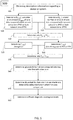
- FIG. 1 shows an exemplary processing system with multiple processing units according to some aspects of the present disclosure
- FIG. 2 shows an an exemplary method for functional safety analysis according to some aspects of the present disclosure
- FIGS. 3-4 show an an exemplary executed Dependent Failure Analysis (DFA) and associated results according to some aspects of the present disclosure
- FIG. 5 shows an exemplary method for improved or enhanced determination or estimation of software diagnostic coverage of a device/system
- FIGS. 6-7 show exemplary diagnostic coverage results.
- a method for performing functional safety analysis on a system with multiple processing units may include obtaining or accessing, by one or more computing devices, description information regarding the system; determining, by the one or more computing devices, one or more failure modes (FMs) of the system from the description information; determining, by the one or more computing devices, one or more dependent failure initiators (DFIs) from the FMs; determining, by the one or more computing devices, a portion ( ⁇ SM>_ideal_DC) of the one or more DFIs covered by core comparison without consideration of dependent failures; determining, by the one or more computing devices, a portion (p) of the one or more DFIs that can potentially lead to dependent failure; determining, by the one or more computing devices, a portion (NDF) of the one or more DFIs that cannot lead to dependent failure; determining, by the one or more computing devices, from the
- a method for performing functional safety analysis on a system with multiple processing units may include obtaining or accessing, by one or more computing devices, description information regarding the system; determining, by the one or more computing devices, an amount of core data (D comp ) compared within a process safety time (PST) or a fault tolerant time (FTTI); determining, by the one or more computing devices, a total amount of core data (D out ) compared within the process safety time (PST) or the fault tolerant time (FTTI); determining, by the one or more computing devices, a ratio of D comp to D out ; determining, by the one or more computing devices, a throughput (T comp ) of the system; determining, by the one or more computing devices, an amount of data (T out ) produced in the PST or the FTTI; determining, by the one or more computing devices, a
- Various embodiments of the present disclosure can be implemented in digital electronic circuitry, in tangibly-embodied computer software or firmware, in computer hardware, including the structures disclosed in this specification and their structural equivalents, or in combinations of one or more of them. That is, various embodiments of the present disclosure may be implemented as one or more computer programs, i.e., one or more modules of computer program instructions encoded on a tangible-non transitory computer readable medium for execution by, or to control the operation of, data processing apparatus.
- a computer program (which may also be referred to or described as a program, software, a software application, a module, a software module, a script, or code) can be written in any form of programming language, including compiled or interpreted languages, or declarative or procedural languages, and it can be deployed in any way, including as a stand-alone program or as a module, component, subroutine, or another unit suitable for use in a computing environment.
- a computer program may, but need not, correspond to a file in a file system.
- a program can be stored in a portion of a file that holds other programs or data, e.g., one or more scripts stored in a markup language document, in a single file dedicated to the program in question, or in multiple coordinated files, e.g., files that store one or more modules, subprograms, or portions of code.
- a computer program can be deployed to be executed on one computer or on multiple computers that are located at one site or distributed across various locations and interconnected by a communication network.
- the processes and logic flows described in this specification can be performed by one or more programmable computers executing one or more computer programs to perform functions by operating on input data and generating output.
- the processes and logic flows can also be performed by, and apparatus can also be implemented as, special purpose logic circuitry, e.g., an FPGA (field programmable gate array) or an ASIC (application specific integrated circuit).
- special purpose logic circuitry e.g., an FPGA (field programmable gate array) or an ASIC (application specific integrated circuit).
- Computers suitable for the execution of a computer program include, by way of example, can be based on general or special purpose microprocessors or both, or any other kind of central processing unit.
- a central processing unit will receive instructions and data from a read-only memory or a random access memory or both.
- the essential elements of a computer are a central processing unit for performing or executing instructions and one or more memory devices for storing instructions and data.
- a computer may also be operatively configured coupled to receive data from or transfer data to, or both, one or more mass storage devices for storing data, e.g., magnetic, magneto-optical disks, or optical disks.
- mass storage devices for storing data, e.g., magnetic, magneto-optical disks, or optical disks.
- a computer need not have such devices.
- a computer can be embedded in another suitable device, e.g., a smartphone, a tablet device, a Global Positioning System (GPS) receiver, or a portable storage device, e.g., a universal serial bus (USB) flash drive, to name just a few.
- a smartphone e.g., a smartphone, a tablet device, a Global Positioning System (GPS) receiver, or a portable storage device, e.g., a universal serial bus (USB) flash drive, to name just a few.
- GPS Global Positioning System
- USB universal serial bus
- Computer readable media suitable for storing computer program instructions and data include all forms of non-volatile memory, media and memory devices, including by way of example semiconductor memory devices, e.g., EPROM, EEPROM, and flash memory devices; magnetic disks, e.g., internal hard disks or removable disks; magneto-optical disks; and CD ROM and DVD-ROM disks.
- semiconductor memory devices e.g., EPROM, EEPROM, and flash memory devices
- magnetic disks e.g., internal hard disks or removable disks
- magneto-optical disks e.g., CD ROM and DVD-ROM disks.
- the processor and the memory can be supplemented by, or incorporated in, special purpose logic circuitry.
- Embodiments of the subject matter described in this specification can be implemented in a computing system that includes a back-end component, e.g., as a data server, or that includes a middleware component, e.g., an application server, or that includes a front-end component, e.g., a client computer having a graphical user interface or a Web browser through which a user can interact with an implementation of the subject matter described in this specification, or any combination of one or more such back-end, middleware, or front-end components.
- the components of the system can be interconnected by any form or medium of digital data communication, e.g., a communication network. Examples of communication networks include a local area network (“LAN”) and a wide area network (“WAN”), e.g., the Internet.
- LAN local area network
- WAN wide area network
- the computing system can include clients and servers.
- a client and server are generally remote from each other and typically interact through a communication network.
- the relationship of client and server arises by computer programs running on the respective computers and having a client-server relationship to each other.
- any computer instructions, program, or software may be stored on any suitable non-transitory computer-readable storage media.
- a device or system implementing redundancy is a system with multi-processing elements, where the software (SW) is implemented in a redundant way, so implementing a Loosely Coupled Lock Step (LCLS).
- SW software
- LCLS Loosely Coupled Lock Step
- many different parameters contribute to the definition or determination of the diagnostic coverage for a system implementing LCLS.
- FIG. 1 shows an exemplary processing system 100 including a pair of processing modules 110 , 120 .
- the system includes multiple processing units or processing modules which may be independent CPUs, or “cores.”
- the system 100 may run or execute one or more applications or programs.
- the example of FIG. 1 is an embodiment that includes two cores, but this not necessarily so as other amount or number of cores may be implemented in a processing system.
- the system 100 may include a comparator 130 operatively connected to each of the cores, 110 and 120 .
- the comparator may be implemented as another processing unit that is configured to, among other things, to compare that data, information, or messages associated with or coming from each of the cores 110 , 120 .
- the cores 110 and 120 may execute, or be configured to implement the same application.
- a particular fault or failure mode may be known or associated with the application being executed on one of the cores. This FM or fault may be known to appear or occur at with a specific failure rate, ⁇ SR .
- a particular failure mode e.g., FM 1
- FM 1 may produce a wrong core output.
- the system 100 includes the comparator 130 to run a comparison between the two core.
- the comparator unit 130 may then, as a safety mechanism (SM) detect the failure, and initiate an action or countermeasure to remedy or correct or handle such error.
- SM safety mechanism
- a fault 140 may occur on core 110 .
- the comparator 130 may determine a fault, failure, or error with a comparison of core output from core 110 with core output from core 120 , and then initiate an appropriate or suitable countermeasure, for example starting the sequence for leading the system into a safe state.
- the diagnostic coverage or a measure of a system's ability to detect failures may be calculated to be 99% based on FMEDA.
- DC determined by FMEDA does not consider dependent faults or errors. That is, there is no quantification of the diagnosis of dependent errors in FMEDA. That is while a particular fault or defect associated with a failure mode may be known or detectable and considered in FMEDA, but a dependent fault or cascading or arising the initial fault may not be part of the analysis.
- error 150 could be a failure in the HW or SW logic handling data to be stored in the memory which could affect in the same way the data generated by two CPUs. This can lead to wrong data without fault detection (both data are wrong but equal).
- the method includes determining the failure modes which are dependent failure initiators (DFIs).
- the one or more processing devices may extract, determine or selectively identify the failure modes (FMs) that are DFIs from the description information of the system/device.
- FMs failure modes
- safety mechanisms such as in the case of a multi-core or multi-processing unit electrical component/system/device, may include comparisons, e.g., a core comparison as shown in the example of FIG. 1 .
- the one or more processing devices may determine this value from the description information. For example, the one or more processing devices may analyze the description information to determine this percentage.
- the method includes determining coverage of the portion of DFIs that can lead to dependent failure and can be covered by safety mechanisms other than a comparison safety mechanism or redundancy safety mechanism (K).
- K is the estimated coverage of the safety mechanism mitigating the dependent failure.
- the total K 1 ⁇ (1 ⁇ K_ 1 )*(1 ⁇ K_ 2 )* . . . *(1 ⁇ K_n).
- this determination may be accomplished by one or more processing devices.
- core comparison by comparator 130 may be one safety mechanism assigned to mitigate or cover one or more failure modes.
- the device of FIG. 1 may include more or additional safety mechanisms. That is, for the system 100 , a DFI (e.g., fault 150 ) that cannot be covered by a core comparison or redundancy safety mechanism may be covered another safety mechanism built in the device 100 .
- a DFI e.g., fault 150
- the method includes determining an improved FMEDA diagnostic coverage including coverage of DFIs provided by core comparison and other safety mechanisms.
- This diagnostic coverage is based on the determined percentage of DFIs that are covered by existing safety mechanism ( ⁇ SM 1 >_ideal_DC), the determined percentage of DFIs that can lead to a potential dependent failure (p), the determined percentage of DFIs that cannot lead dependent failure(s) (NDF), and the determined coverage of the portion of DFIs that can lead to dependent failure and can be covered by safety mechanisms other than a comparison safety mechanism or redundancy safety mechanism (K).
- FIG. 3 shows an exemplary executed Dependent Failure Analysis (DFA) at least with respect to one failure mode.
- DFA Dependent Failure Analysis
- FIG. 3 includes exemplary data that define parameters used in the DFA as well as output or values determined in or for the DFA process.
- entry item 302 indicates or identifies the core (e.g., Intel Atom®) which is the subject of the DFA.
- Entry item 304 indicates a DFI which has been identified from description data, which in this case is an Incorrect Instruction Execution.
- Entry item 306 indicates whether core includes a Loosely Coupled Lock Step (LCLS).
- LCLS Loosely Coupled Lock Step
- Entry item 308 specifies details of the identified dependent failure initiator of 304 .
- entry item 310 indicates whether the LCLS feature of the core was active for the identified DFI of 304 .
- DFA analysis determines a transient undetected dependent failure rate associated with the failure, shown in 312 and a permanent undetected dependent failure rate associated with the failure mode, shown in 314 .
- items 316 and 318 show respectively the determined permanent and transient (p)—the percentage of DFIs that can potentially lead to dependent failure.
- computation of failure rate may be different if considering the same failure mode but a different fault model (permanent or transient).
- the calculation, from here, of LambdaDF can also be different. Such data may be based on the description and analysis described before.
- the effectiveness of a safety mechanisms can be different in terms of diagnostic coverage. For example a periodic check is typically not effective for transient failures.
- the method may include indicating, at 320 , the effect(s) or possible effect(s) of the dependent failure of 304 .
- an exemplary DFA may also indicate at entry 322 the type of DFI specified in 304 .
- the DFI is specified as “CAS.”
- FIG. 3 shows or indicates the safety mechanisms already accounted for in the FMEDA.
- the permanent and the transient determined FMEDA diagnostic coverage is respectively shown or indicated.
- the DFA diagnostic coverage e.g., the determined DFA diagnostic coverage, (e.g., determined in the method of FIG. 2 ) is shown for the permanent and transient case.
- Priority percentage can be informative data, e.g., a ranking provided which is useful to understand where to concentrate the analysis in order to achieve a possible diagnostic coverage target.
- FIG. 4 further, like FIG. 3 , shows an exemplary executed Dependent Failure Analysis (DFA).
- DFA Dependent Failure Analysis
- FIG. 4 is an example of the total results of a DFA analysis, for a single failure mode.
- Entry 404 indicates the specific IP core FMEDA entry
- Entry under 406 indicates whether the core has or implements LCLS, entry 408 indicates a determined permanent FMEDA diagnostic coverage while entry under 410 indicates a determined transient FMEDA diagnostic coverage.
- entries under 412 and 414 respectively show the determined residual failure rate, Lambda_Rf, contribution.
- Entry under 416 identifies the LCLS safety mechanism for the core, and entries under 418 and 420 respectively determine the permanent and transient diagnostic coverage. Entry 416 indicates the LCLS entry in the safety mechanisms table and it is based on this analysis (NEW), with respect the one previously considered in a “classic” FMEDA analysis
- the diagnostic coverage of SW comparison is defined as “high” but always linked with disclaimers.
- the “quality of comparison” is related to the observability of the data, e.g., the amount of data compared both in number and in time.
- diagnostic coverage is related to the capability of a safety mechanism to detect faults within the fault handling time interval (in ISO 26262, related to fault tolerant time interval (FTTI), or process safety time in IEC 61508).
- FTTI fault tolerant time interval
- a fault being not observed within the period of observation may cause either a failure during the period in which the fault is not compared or may accumulate with other similar faults and cause the same failure in both channels.
- a fault in Core 0 , 110 being not observed during the period of comparison may cause cascading failures affecting the data of core 1 , 120 .
- a fault may affect the configuration of the memory controller or the communication channel, so affecting the transmission of core 1 data to the comparator. Further, such a fault may affect shared resources (e.g., change the configuration of power or clock settings), so affecting the generation of Core 1 data.
- a fault in Core 0 , 110 may remain silent for a particular time and then become observable only when another fault has already occurred in the same function in Core 1 , 120 . As a result, this causes the comparator not to detect the failure. In various implementations, this is not so unlikely because aging effects or voltage/temperature effects (single fault scenario) may cause similar failures in both cores.
- FIG. 5 shows, according to an exemplary embodiment, an electronic method for improved or enhanced determination or estimation of software diagnostic coverage of a device/system with a loosely coupled lock step (LCLS).
- LCLS loosely coupled lock step
- the method can be implemented by one or more processing devices.
- the one or more processing devices may execute program instructions, stored on non-transitory media, to perform the method.
- the method includes obtaining description information for a device/system.
- the device/system in accordance with exemplary embodiments, may implement a software lock step.
- the electrical component e.g., the device or system may resemble or be similar to device 100 in the example of FIG. 1 .
- various parameter mays be determined, identified or calculated.
- the method includes determining, a number or an amount of core data D comp compared within process safety time (PST) or fault tolerant time (FTTI).
- PST process safety time
- FTTI fault tolerant time
- the method includes determining, a total number or amount of core data D out compared within process safety time (PST) or fault tolerant time (FTTI).
- PST process safety time
- FTTI fault tolerant time
- the method includes determining a ratio of D comp to D out .
- D out can be the total number of output variables for each SW module and D comp can be the total number of variables exposed for comparison.
- the method includes determining T comp , a throughput of a core or system, e.g., the frequency at which data is sent out for comparison. This is a value indicating how much data is compared in a PST or FTTI.
- the method includes determining T out , which is a value indicating how much data is produced in a PST or FTTI.
- the method includes determining a ratio of T out to T comp .
- this ratio can indicate how often the output variables are generated with respect to how often the variables are compared.
- the method includes determining the probability p, that non-compared data (e.g., data not sent or provided for core comparisoni) may interfere with the other core.
- the method includes determining the probability k, that output data (e.g., core output data) that can interfere is detected by other safety mechanisms.
- the method includes determining the software (SW) diagnostic coverage DC comp .
- the DC comp may be calculated as follows:
- DC comp D comp D out ⁇ T out T comp + ( 1 - D comp D out ⁇ T out T ⁇ comp ) ⁇ ( 1 - p ) + ( 1 - D comp D out ⁇ T out T ⁇ comp ) ⁇ p ⁇ k
- DC comp D comp D out ⁇ T out T comp + ( 1 - D comp D out ⁇ T out T ⁇ comp ) ⁇ ( 1 - p ) + ( 1 - D comp D out ⁇ T out T ⁇ comp ) ⁇ p ⁇ k
- another exemplary device may include SW lock step that generates 1000 data each FTTI with a throughput of 1 data each 0.001 ms and comparing 1 data each 0.1 ms.
- the determined p or probability that non-compared data of the device can generate interference can be exemplary 50%, and k or the probability of that those data are detected by the existing safety mechanisms may be 60%.
- IP FMEDAs that impact LCLS are considered.
- IP FMEDAs may include or be a source of: List of failure modes (FMs) that LCLS is supposed to cover (potential DFIs), failure rates.
- FMs List of failure modes
- DFIs potential DFIs
- electronic methods to implement DFA for LCLS described herein include:
- the method may also consider or rely on:
- FIG. 6 shows the diagnostic coverage under existing FMEDA approach. The corresponding portions of the overall failure rate are
- LambdaNS is the failure rate portion of the failure mode for which any fault could potentially leads error/failure/safety goal violation.
- FIG. 7 shows the diagnostic coverage under existing FMEDA approach. The corresponding portions of the overall failure rate are
- the DC is evaluated, at first, in the case of a comparison done only on the final algorithm results or any way each diagnostic test interval (DTI).
- DTI diagnostic test interval
- the application SW may executing computations, which based on this, results are provided. It can be represented by an algorithm.
- Sensitivity analysis considering of the parameters may be done at the end. Sensitivity analysis may be the evaluation of the impact on the analysis when considering different values of Dcomp/Dout, Tcomp/Tout.
- DC comp D comp /D out ⁇ T out /T comp +(1 ⁇ D comp /D out ⁇ T out /T comp ) ⁇ (1 ⁇ p int )+(1 ⁇ D comp /D out ⁇ T out /T comp ) ⁇ p int ⁇ k int May be reduced to: DC comp ⁇ 1 ⁇ p int ⁇ (1 ⁇ k int )
- DC LCLS_ideal_DC ⁇ sum_ j ((1 ⁇ sum_ i _ j ( p _ i _ j ⁇ (1- k _ i _ j ) ⁇ (1- NDF _ i _ j )) ⁇ Scenario_ j )
- IP and scenarios to be considered are based on a specific application model (e.g., IP: Atom®, System Agent®, Dunit®.
- IP Atom®, System Agent®, Dunit®.
- various scenarios may be High ASIL (automo 1 tive safety integrity level), Low ASIL tasks, OS, MW (middleware), etc.
- 1 ASILB is a value of the Automotive Safety Integrity Level
- Example 1 is a method for performing functional safety analysis on a system with multiple processing units, wherein the system includes a comparator to compare data from a first core with data from a second core, the method including obtaining or accessing, by one or more computing devices, description information regarding the system; determining, by the one or more computing devices, one or more failure modes (FMs) of the system from the description information; determining, by the one or more computing devices, one or more dependent failure initiators (DFIs) from the FMs; determining, by the one or more computing devices, a portion ( ⁇ SM>_ideal_DC) of the one or more DFIs covered by core comparison without consideration of dependent failures; determining, by the one or more computing devices, a portion (p) of the one or more DFIs that can potentially lead to dependent failure; determining, by the one or more computing devices, a portion (NDF) of the one or more DFIs that cannot lead to dependent failure; determining, by the one or more computing devices, from the portion of the one or more DFIs
- K_n is the coverage associated with SM_n.
- Example 5 is a method for performing functional safety analysis on a system with multiple processing units, wherein the system includes a comparator to compare data from a first core with data from a second core, the method can include obtaining or accessing, by one or more computing devices, description information regarding the system; determining, by the one or more computing devices, an amount of core data (D comp ) compared within a process safety time (PST) or a fault tolerant time (FTTI); determining, by the one or more computing devices, a total amount of core data (D out ) compared within the process safety time (PST) or the fault tolerant time (FTTI); determining, by the one or more computing devices, a ratio of D comp to D out ; determining, by the one or more computing devices, a throughput (T comp ) of the device; determining, by the one or more computing devices, an amount of data (T out ) produced in the PST or the FTTI; determining, by the one or more computing devices, a ratio of T out to T comp
- Example 6 the subject matter of Example 5, wherein the estimate of the DC comp is calculated by the one or more computers according to the formula:
- DC comp D comp D out ⁇ T out T comp + ( 1 - D comp D out ⁇ T out T ⁇ comp ) ⁇ ( 1 - p ) + ( 1 - D comp D out ⁇ T out T ⁇ comp ) ⁇ p ⁇ k
- Example 7 the subject matter of Example 5, wherein the obtained information indicates the system includes a plurality of software modules, and wherein D out is a total number of output variables for each SW module and D comp is a total number of variables exposed for comparison.
- Example 8 the subject matter of Example 5, wherein the ratio of T out to T comp indicates a rate at which output variables are generated with respect to how often the variables are compared.
- Example 9 is a computer program product including a non-transitory computer-readable storage medium having program instructions stored thereon that when executed by at least processor, cause the at least one processor to perform a method of functional safety analysis of a system with multiple processing units, the system including a comparator to compare data from a first core with data from a second core, wherein instructions can cause the at least one processor to obtain or access description information regarding the system; determine one or more failure modes (FMs) of the system from the description information; determine one or more dependent failure initiators (DFIs) from the FMs; determine a portion ( ⁇ SM>_ideal_DC) of the one or more DFIs covered by core comparison without consideration of dependent failures; determine a portion (p) of the one or more DFIs that can potentially lead to dependent failure; determine a portion (NDF) of the one or more DFIs that cannot lead to dependent failure; determine from the portion of the one or more DFIs that can lead to dependent failure, the coverage (K) provided by safety mechanisms other than core comparison; and determine a
- Example 13 is a computer program product including a non-transitory computer-readable storage medium having program instructions stored thereon that when executed by at least processor, cause the at least one processor to perform a method of functional safety analysis of a system with multiple processing units, the system including a comparator to compare data from a first core with data from a second core, wherein instructions can cause the at least one processor to obtain or access description information regarding the system; determine an amount of core data (D comp ) compared within a process safety time (PST) or a fault tolerant time (FTTI); determine a total amount of core data (D out ) compared within the process safety time (PST) or the fault tolerant time (FTTI); determine a ratio of D comp to D out ; determine a throughput (T comp ) of the system; determine an amount of data (T out ) produced in the PST or the FTTI; determine a ratio of T out to T comp ; determine a probability (p), that non compared data may interfere with another core; determine a probability (k),
- Example 14 the subject matter of Example 13, wherein the estimate of the DC comp can be calculated according to the formula:
- DC comp D comp D out ⁇ T out T comp + ( 1 - D comp D out ⁇ T out T ⁇ comp ) ⁇ ( 1 - p ) + ( 1 - D comp D out ⁇ T out T ⁇ comp ) ⁇ p ⁇ k
- Example 15 the subject matter of Example 13, wherein the obtained information can optionally indicate the system includes a plurality of software modules, and wherein D out is a total number of output variables for each SW module and D comp is a total number of variables exposed for comparison.
- Example 16 the subject matter of Example 13, wherein the ratio of T out to T comp can optionally indicate a rate at which output variables are generated with respect to how often the variables are compared.
Landscapes
- Engineering & Computer Science (AREA)
- Theoretical Computer Science (AREA)
- Physics & Mathematics (AREA)
- General Physics & Mathematics (AREA)
- General Engineering & Computer Science (AREA)
- Quality & Reliability (AREA)
- Mathematical Physics (AREA)
- Data Mining & Analysis (AREA)
- Computational Mathematics (AREA)
- Mathematical Analysis (AREA)
- Mathematical Optimization (AREA)
- Pure & Applied Mathematics (AREA)
- Operations Research (AREA)
- Algebra (AREA)
- Databases & Information Systems (AREA)
- Software Systems (AREA)
- Hardware Redundancy (AREA)
- Health & Medical Sciences (AREA)
- Biomedical Technology (AREA)
- Test And Diagnosis Of Digital Computers (AREA)
Abstract
Description
DC=<SM>_ideal_DC*(1−p*(1−NDF)*(1−*K)).
For a plurality of DFIs the diagnostic coverage is:
DC=<SM>_ideal_DC×sumj((1−sumij(p ij×(1−k ij)×(1−NDF ij))×Scenarioj)
-
- where sum_j is the summation from 1 to j of content enclosed in the parentheses
- i is an index that ranges across all the DFIs (e.g., index for each respective DFI, DFI_i);
- j is an index that ranges across all the scenarios (e.g., index for each respective scenario, Scenario_j);
- pij is the fraction of the i-th DFI that may lead to a failure in the j-th scenario;
- kij is the fraction of the i-th DFI that in the j-th scenario may be covered by other safety mechanisms;
- NDFij is the fraction of the i-th DFI that in the j-th scenario may not lead to a dependent failure;
- Scenarioj is the j-th scenario, considering failure mode distribution of different use cases (e.g., OS running, middleware running, etc., but it can be extended to any use case)—that is, Scenarios is the percentage of the overall device failure rate associated with the specific Use Case/Scenario
D comp /D out=1; T out /T comp=1
DCcomp=100%
D comp /D tot=1/1000=0.001, T out /T comp=0.001/0.1=0.01, p=0.5, k=0.6
DCcomp=80%.
D comp /D tot=1/1000=0.001, T out /T comp=0.001/0.1=0.01, p=0.5, k=0
DCcomp=90%
D comp /D tot=1/1000=0.001, T out /T comp=0.001/0.1=0.01, p=0.5, k=0
DCcomp=90%
-
- Identifying portion(s) of the potential dependent failure initiators (DFIs) that will not lead to dependent failure (DF)
- Identifying DFIs leading to an impact on the LCLS comparisons. (This is done considering different scenarios)
- Evaluating additional safety mechanisms (SMs) to decrease the impact of DF
- Computing the LCLS coverage per IP core or per Hardware portion
-
- (1) The coverage provided by safety mechanisms already covering the specific FMEDA line or item. (Further, it may be assumed that the portion of hardware (HW) of a device/system covered by these SMs does not lead to DF(s) affecting LCLS.)
- (2) The coverage provided by safety mechanisms not yet covering the specific FMEDA line but already present in the overall FMEDA
-
- LambdaSafe
- LambdaNS by SM other than LCLS=
- LambdaNS covered by LCLS
- LambdaRF
-
- LamdaRF=residual failure rate
-
- LambdaSafe
- LambdaNS by SM other than LCLS
- LambdaNS covered by LCLS
- LambdaRF
D comp /D out=0; and T out /T comp→0):
DCcomp =D comp /D out ×T out /T comp+(1−D comp /D out ×T out /T comp)×(1−p int)+(1−D comp /D out ×T out /T comp)×p int ×k int
May be reduced to:
DCcomp×1−p int×(1−k int)
DC=LCLS_ideal_DC×sum_j((1−sum_i_j(p_i_j×(1-k_i_j)×(1-NDF_i_j))×Scenario_j)
DC=<SM>_ideal_DC*(1−p*(1−NDF)*(1−*K)).
K=1−(1−K_1)*(1−K_2)* . . . *(1−K_n)
DC=<SM>_ideal_DC×sum_j((1−sum_i_j(p_i_j×(1-k_i_j)×NDF_i_j))×Scenario_j)
where
-
- i is an index that ranges across all the DFIs;
- j is an index that ranges across all the scenarios;
- pij is the fraction of the i-th DFI that may lead to a failure in the j-th scenario;
- kij is the fraction of the i-th DFI that in the j-th scenario may be covered by other safety mechanisms;
- NDFij is the fraction of the i-th DFI that in the j-th scenario may not lead to a dependent failure;
- Scenario_j is the j-th scenario, considering failure mode distribution of different use cases.
DC=<SM>_ideal_DC*(1−p*(1−NDF)*(1−*K)).
K=1−(1−K_1)*(1−K_2)* . . . *(1−K_n)
-
- wherein K_n is the coverage associated with SM_n.
DC=<SM>_ideal_DC×sum_j((1−sum_i_j(p_i_j×(1−k_i_j)×(1−NDF_j))×Scenario_j)
-
- i is an index that ranges across all the DFIs;
- j is an index that ranges across all the scenarios;
- pij is the fraction of the i-th DFI that may lead to a failure in the j-th scenario;
- kij is the fraction of the i-th DFI that in the j-th scenario may be covered by other safety mechanisms;
- NDFij is the fraction of the i-th DFI that in the j-th scenario may not lead to a dependent failure;
- Scenario_j is the j-th scenario, considering failure mode distribution of different use cases.
Claims (14)
DC=<SM>_ideal_DC*(1−p*(1−NDF)*(1−*K)).
K=1−(1−K_1)*(1−K_2)* . . . *(1−K_n)
DC=<SM>_ideal_DC×sum_j((1−sum_i_j(p_i_j×(1−k_i_j)×(1−NDF_j))×Scenario_j)
DC=<SM>_ideal_DC*(1−p*(1−NDF)*(1−*K)).
K=1−(1−K_1)*(1−K_2)* . . . *(1−K_n)
DC=<SM>_ideal_DC×sum_j((1−sum_i_j(p_i_j×(1−k_i_j)×(1−NDF_j))×Scenario_j)
Priority Applications (1)
| Application Number | Priority Date | Filing Date | Title |
|---|---|---|---|
| US16/145,347 US10929253B2 (en) | 2018-09-28 | 2018-09-28 | Systems and methods for safety analysis including consideration of dependent failures |
Applications Claiming Priority (1)
| Application Number | Priority Date | Filing Date | Title |
|---|---|---|---|
| US16/145,347 US10929253B2 (en) | 2018-09-28 | 2018-09-28 | Systems and methods for safety analysis including consideration of dependent failures |
Publications (2)
| Publication Number | Publication Date |
|---|---|
| US20190050300A1 US20190050300A1 (en) | 2019-02-14 |
| US10929253B2 true US10929253B2 (en) | 2021-02-23 |
Family
ID=65274150
Family Applications (1)
| Application Number | Title | Priority Date | Filing Date |
|---|---|---|---|
| US16/145,347 Expired - Fee Related US10929253B2 (en) | 2018-09-28 | 2018-09-28 | Systems and methods for safety analysis including consideration of dependent failures |
Country Status (1)
| Country | Link |
|---|---|
| US (1) | US10929253B2 (en) |
Families Citing this family (2)
| Publication number | Priority date | Publication date | Assignee | Title |
|---|---|---|---|---|
| WO2022064532A1 (en) * | 2020-09-24 | 2022-03-31 | Intel Corporation | Quantitative analysis and diagnostic coverage (dc) calculation of application-oriented safety measures in complex systems |
| DE102020128026A1 (en) * | 2020-10-23 | 2022-04-28 | Pilz Gmbh & Co. Kg | Control device with protection module |
Citations (9)
| Publication number | Priority date | Publication date | Assignee | Title |
|---|---|---|---|---|
| US20050210331A1 (en) * | 2004-03-19 | 2005-09-22 | Connelly Jon C | Method and apparatus for automating the root cause analysis of system failures |
| US20060156215A1 (en) * | 2005-01-11 | 2006-07-13 | International Business Machines Corporation | Error type identification circuit for identifying different types of errors in communications devices |
| US20070220381A1 (en) * | 2006-02-17 | 2007-09-20 | Yu Huang | Enhanced diagnosis with limited failure cycles |
| US20120066657A1 (en) * | 2010-09-13 | 2012-03-15 | International Business Machines Corporation | Method of designing an integrated circuit based on a combination of manufacturability, test coverage and, optionally, diagnostic coverage |
| US20140223233A1 (en) * | 2013-02-07 | 2014-08-07 | International Business Machines Corporation | Multi-core re-initialization failure control system |
| US20180329371A1 (en) * | 2017-05-09 | 2018-11-15 | Mediatek Inc. | Data processing system with logic functional self-checking and associated data processing method |
| US20180336067A1 (en) * | 2017-05-17 | 2018-11-22 | Samsung Electronics Co., Ltd. | Method and apparatus for data processing based on multicore |
| US20190278677A1 (en) * | 2018-03-07 | 2019-09-12 | Nxp B.V. | Runtime Software-Based Self-Test with Mutual Inter-Core Checking |
| US20190303260A1 (en) * | 2018-03-29 | 2019-10-03 | Arm Ltd. | Device, system and process for redundant processor error detection |
-
2018
- 2018-09-28 US US16/145,347 patent/US10929253B2/en not_active Expired - Fee Related
Patent Citations (9)
| Publication number | Priority date | Publication date | Assignee | Title |
|---|---|---|---|---|
| US20050210331A1 (en) * | 2004-03-19 | 2005-09-22 | Connelly Jon C | Method and apparatus for automating the root cause analysis of system failures |
| US20060156215A1 (en) * | 2005-01-11 | 2006-07-13 | International Business Machines Corporation | Error type identification circuit for identifying different types of errors in communications devices |
| US20070220381A1 (en) * | 2006-02-17 | 2007-09-20 | Yu Huang | Enhanced diagnosis with limited failure cycles |
| US20120066657A1 (en) * | 2010-09-13 | 2012-03-15 | International Business Machines Corporation | Method of designing an integrated circuit based on a combination of manufacturability, test coverage and, optionally, diagnostic coverage |
| US20140223233A1 (en) * | 2013-02-07 | 2014-08-07 | International Business Machines Corporation | Multi-core re-initialization failure control system |
| US20180329371A1 (en) * | 2017-05-09 | 2018-11-15 | Mediatek Inc. | Data processing system with logic functional self-checking and associated data processing method |
| US20180336067A1 (en) * | 2017-05-17 | 2018-11-22 | Samsung Electronics Co., Ltd. | Method and apparatus for data processing based on multicore |
| US20190278677A1 (en) * | 2018-03-07 | 2019-09-12 | Nxp B.V. | Runtime Software-Based Self-Test with Mutual Inter-Core Checking |
| US20190303260A1 (en) * | 2018-03-29 | 2019-10-03 | Arm Ltd. | Device, system and process for redundant processor error detection |
Also Published As
| Publication number | Publication date |
|---|---|
| US20190050300A1 (en) | 2019-02-14 |
Similar Documents
| Publication | Publication Date | Title |
|---|---|---|
| US10621362B2 (en) | Method for automatically detecting security vulnerability based on hybrid fuzzing, and apparatus thereof | |
| Li et al. | Software vulnerability detection using backward trace analysis and symbolic execution | |
| US10185612B2 (en) | Analyzing the availability of a system | |
| US20100275062A1 (en) | Functional Coverage Using Combinatorial Test Design | |
| US20110258602A1 (en) | Method for estimating testing efforts for software unit testing | |
| CN111104319A (en) | Code coverage rate testing method and device, electronic equipment and storage medium | |
| CN108388751A (en) | Void-solid ratio based on dummy experiment system and real system is to analysis method | |
| Reghenzani et al. | Probabilistic-WCET reliability: On the experimental validation of EVT hypotheses | |
| US10929253B2 (en) | Systems and methods for safety analysis including consideration of dependent failures | |
| Hamlet | Predicting dependability by testing | |
| He et al. | A bounded statistical approach for model checking of unbounded until properties | |
| WO2022196219A1 (en) | Program analysis device, program analysis method, and tracing process addition device | |
| WO2019142266A1 (en) | Test case generation device, test case generation method, and test case generation program | |
| GB2504496A (en) | Removing code instrumentation based on the comparison between collected performance data and a threshold | |
| Santos et al. | An empirical study on the influence of context in computing thresholds for Chidamber and Kemerer metrics. | |
| CN114091644A (en) | A technology risk assessment method and system for artificial intelligence products | |
| Amara et al. | An empirical assessment and validation of redundancy metrics using defect density as reliability indicator | |
| CN118860406A (en) | Vulnerability detection method, device, computer equipment and readable storage medium | |
| Pomorova et al. | Assessment of the source code static analysis effectiveness for security requirements implementation into software developing process | |
| CN112182572B (en) | Urban rail interlocking software code static measurement method and system | |
| Schilling et al. | Modeling the reliability of existing software using static analysis | |
| Maul et al. | Fault management algorithm risk assessment for the NASA space launch system | |
| Sawadpong | Toward a defect prediction model of exception handling method call structures | |
| Bishop | SILs and software | |
| Liu et al. | Development of Reliability Measurement Method and Tool for Nuclear Power Plant Safety Software |
Legal Events
| Date | Code | Title | Description |
|---|---|---|---|
| FEPP | Fee payment procedure |
Free format text: ENTITY STATUS SET TO UNDISCOUNTED (ORIGINAL EVENT CODE: BIG.); ENTITY STATUS OF PATENT OWNER: LARGE ENTITY |
|
| STPP | Information on status: patent application and granting procedure in general |
Free format text: DOCKETED NEW CASE - READY FOR EXAMINATION |
|
| AS | Assignment |
Owner name: INTEL CORPORATION, CALIFORNIA Free format text: ASSIGNMENT OF ASSIGNORS INTEREST;ASSIGNORS:CAGNACCI, RICCARDO;MARIANI, RICCARDO;REEL/FRAME:048403/0988 Effective date: 20190213 |
|
| STPP | Information on status: patent application and granting procedure in general |
Free format text: NON FINAL ACTION MAILED |
|
| STPP | Information on status: patent application and granting procedure in general |
Free format text: RESPONSE TO NON-FINAL OFFICE ACTION ENTERED AND FORWARDED TO EXAMINER |
|
| STPP | Information on status: patent application and granting procedure in general |
Free format text: NOTICE OF ALLOWANCE MAILED -- APPLICATION RECEIVED IN OFFICE OF PUBLICATIONS |
|
| STCF | Information on status: patent grant |
Free format text: PATENTED CASE |
|
| FEPP | Fee payment procedure |
Free format text: MAINTENANCE FEE REMINDER MAILED (ORIGINAL EVENT CODE: REM.); ENTITY STATUS OF PATENT OWNER: LARGE ENTITY |
|
| LAPS | Lapse for failure to pay maintenance fees |
Free format text: PATENT EXPIRED FOR FAILURE TO PAY MAINTENANCE FEES (ORIGINAL EVENT CODE: EXP.); ENTITY STATUS OF PATENT OWNER: LARGE ENTITY |
|
| STCH | Information on status: patent discontinuation |
Free format text: PATENT EXPIRED DUE TO NONPAYMENT OF MAINTENANCE FEES UNDER 37 CFR 1.362 |
|
| FP | Lapsed due to failure to pay maintenance fee |
Effective date: 20250223 |