US10922502B2 - Structural unit for a linear actuator - Google Patents
Structural unit for a linear actuator Download PDFInfo
- Publication number
- US10922502B2 US10922502B2 US16/442,738 US201916442738A US10922502B2 US 10922502 B2 US10922502 B2 US 10922502B2 US 201916442738 A US201916442738 A US 201916442738A US 10922502 B2 US10922502 B2 US 10922502B2
- Authority
- US
- United States
- Prior art keywords
- linear actuator
- unit
- structural unit
- sensor
- outer tube
- Prior art date
- Legal status (The legal status is an assumption and is not a legal conclusion. Google has not performed a legal analysis and makes no representation as to the accuracy of the status listed.)
- Expired - Fee Related
Links
Images


Classifications
-
- G—PHYSICS
- G06—COMPUTING OR CALCULATING; COUNTING
- G06K—GRAPHICAL DATA READING; PRESENTATION OF DATA; RECORD CARRIERS; HANDLING RECORD CARRIERS
- G06K7/00—Methods or arrangements for sensing record carriers, e.g. for reading patterns
- G06K7/10—Methods or arrangements for sensing record carriers, e.g. for reading patterns by electromagnetic radiation, e.g. optical sensing; by corpuscular radiation
- G06K7/10009—Methods or arrangements for sensing record carriers, e.g. for reading patterns by electromagnetic radiation, e.g. optical sensing; by corpuscular radiation sensing by radiation using wavelengths larger than 0.1 mm, e.g. radio-waves or microwaves
- G06K7/10297—Methods or arrangements for sensing record carriers, e.g. for reading patterns by electromagnetic radiation, e.g. optical sensing; by corpuscular radiation sensing by radiation using wavelengths larger than 0.1 mm, e.g. radio-waves or microwaves arrangements for handling protocols designed for non-contact record carriers such as RFIDs NFCs, e.g. ISO/IEC 14443 and 18092
-
- F—MECHANICAL ENGINEERING; LIGHTING; HEATING; WEAPONS; BLASTING
- F16—ENGINEERING ELEMENTS AND UNITS; GENERAL MEASURES FOR PRODUCING AND MAINTAINING EFFECTIVE FUNCTIONING OF MACHINES OR INSTALLATIONS; THERMAL INSULATION IN GENERAL
- F16H—GEARING
- F16H25/00—Gearings comprising primarily only cams, cam-followers and screw-and-nut mechanisms
- F16H25/18—Gearings comprising primarily only cams, cam-followers and screw-and-nut mechanisms for conveying or interconverting oscillating or reciprocating motions
- F16H25/20—Screw mechanisms
-
- G—PHYSICS
- G01—MEASURING; TESTING
- G01L—MEASURING FORCE, STRESS, TORQUE, WORK, MECHANICAL POWER, MECHANICAL EFFICIENCY, OR FLUID PRESSURE
- G01L5/00—Apparatus for, or methods of, measuring force, work, mechanical power, or torque, specially adapted for specific purposes
- G01L5/0028—Force sensors associated with force applying means
- G01L5/0033—Force sensors associated with force applying means applying a pulling force
-
- G—PHYSICS
- G01—MEASURING; TESTING
- G01L—MEASURING FORCE, STRESS, TORQUE, WORK, MECHANICAL POWER, MECHANICAL EFFICIENCY, OR FLUID PRESSURE
- G01L5/00—Apparatus for, or methods of, measuring force, work, mechanical power, or torque, specially adapted for specific purposes
- G01L5/0028—Force sensors associated with force applying means
- G01L5/0038—Force sensors associated with force applying means applying a pushing force
-
- G—PHYSICS
- G01—MEASURING; TESTING
- G01L—MEASURING FORCE, STRESS, TORQUE, WORK, MECHANICAL POWER, MECHANICAL EFFICIENCY, OR FLUID PRESSURE
- G01L5/00—Apparatus for, or methods of, measuring force, work, mechanical power, or torque, specially adapted for specific purposes
- G01L5/0061—Force sensors associated with industrial machines or actuators
-
- G—PHYSICS
- G01—MEASURING; TESTING
- G01M—TESTING STATIC OR DYNAMIC BALANCE OF MACHINES OR STRUCTURES; TESTING OF STRUCTURES OR APPARATUS, NOT OTHERWISE PROVIDED FOR
- G01M13/00—Testing of machine parts
- G01M13/02—Gearings; Transmission mechanisms
-
- H—ELECTRICITY
- H02—GENERATION; CONVERSION OR DISTRIBUTION OF ELECTRIC POWER
- H02J—ELECTRIC POWER NETWORKS; CIRCUIT ARRANGEMENTS OR SYSTEMS FOR SUPPLYING OR DISTRIBUTING ELECTRIC POWER; SYSTEMS FOR STORING ELECTRIC ENERGY
- H02J50/00—Circuit arrangements or systems for wireless supply or distribution of electric power
- H02J50/20—Circuit arrangements or systems for wireless supply or distribution of electric power using microwaves or radio frequency waves
-
- H—ELECTRICITY
- H04—ELECTRIC COMMUNICATION TECHNIQUE
- H04L—TRANSMISSION OF DIGITAL INFORMATION, e.g. TELEGRAPHIC COMMUNICATION
- H04L67/00—Network arrangements or protocols for supporting network services or applications
- H04L67/01—Protocols
- H04L67/10—Protocols in which an application is distributed across nodes in the network
- H04L67/1097—Protocols in which an application is distributed across nodes in the network for distributed storage of data in networks, e.g. transport arrangements for network file system [NFS], storage area networks [SAN] or network attached storage [NAS]
-
- H—ELECTRICITY
- H04—ELECTRIC COMMUNICATION TECHNIQUE
- H04L—TRANSMISSION OF DIGITAL INFORMATION, e.g. TELEGRAPHIC COMMUNICATION
- H04L67/00—Network arrangements or protocols for supporting network services or applications
- H04L67/01—Protocols
- H04L67/12—Protocols specially adapted for proprietary or special-purpose networking environments, e.g. medical networks, sensor networks, networks in vehicles or remote metering networks
-
- H—ELECTRICITY
- H04—ELECTRIC COMMUNICATION TECHNIQUE
- H04W—WIRELESS COMMUNICATION NETWORKS
- H04W4/00—Services specially adapted for wireless communication networks; Facilities therefor
- H04W4/30—Services specially adapted for particular environments, situations or purposes
- H04W4/38—Services specially adapted for particular environments, situations or purposes for collecting sensor information
-
- H—ELECTRICITY
- H04—ELECTRIC COMMUNICATION TECHNIQUE
- H04W—WIRELESS COMMUNICATION NETWORKS
- H04W4/00—Services specially adapted for wireless communication networks; Facilities therefor
- H04W4/80—Services using short range communication, e.g. near-field communication [NFC], radio-frequency identification [RFID] or low energy communication
Definitions
- United States patent application publication US 2019/0048988 A1 and its counterpart international patent application WO2017/048788A1 disclose a linear actuator having a tube and a structural unit that is able to be extended from the tube.
- the linear actuator has a sensor.
- Further prior art is disclosed by documents German published patent application DE 102010050837 A1, Japanese patent application JP 2005201390 A, U.S. patent application US 2005/0255186 A1 and its counterpart European patent application EP 1595681 A1, and U.S. patent application publications US 2006/0113940 A1 and US 2008/0065354 A1.
- a structural unit for a linear actuator in particular a spindle drive unit, the structural unit comprising:
- a configuration configured to transmit data by way of electromagnetic radiation and/or configured to wirelessly absorb energy and to then electrically supply at least one electrical load with wirelessly absorbed energy.
- a structural unit in particular a spindle unit, for a linear actuator, which unit is designed to transmit data by way of electromagnetic radiation and/or is designed to wirelessly absorb energy and then electrically supply at least one electrical load with wirelessly absorbed energy.
- “Wireless” energy absorption should be understood to mean energy absorption that differs from energy absorption that takes place exclusively through electric current that flows from a unit that outputs energy to a unit that absorbs energy through a conductor consisting of a solid body. According to the invention, a long service life is achieved. Wear to cables is in particular able to be avoided.
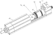
- FIG. 1 shows a perspective and partly broken-away view of a linear actuator according to the invention
- FIG. 2 shows a cross section of the linear actuator
- FIG. 3 shows a structural unit and a threaded spindle of the linear actuator
- FIG. 4 shows a perspective view of a cross section of the structural unit together with the threaded spindle
- FIG. 5 shows a longitudinal section through the linear actuator.
- the linear actuator has an outer tube 10 and a structural unit 12 that is able to be partly moved out of the tube and back into the tube 10 in a straight line relative to the tube.
- the movement is brought about by a non-illustrated motor that is able to turn a threaded spindle 40 (see, FIGS.
- the linear actuator furthermore has a sensor unit 14 that is designed to measure deformation characteristic variables of the structural unit 12 .
- the sensor unit 14 is arranged at a radial outer region 16 of the structural unit.
- a tube 42 of the structural unit 12 comprises a wall 18 of the structural unit.
- the wall 18 has a recess 26 that is designed as a through-hole of the tube.
- the sensor unit 14 is arranged in the recess 26 and bears on a boundary of the recess 26 along a circumference of the recess 26 .
- the sensor unit 14 has the shape of a circular cylinder, but may in principle also have another shape.
- both the recess 26 and the sensor unit 14 have a circular shape, as a result of which easy and inexpensive manufacturability for both the recess 26 and the sensor unit 14 is ensured.
- the sensor unit 14 has a first strain gauge 20 whose longitudinal direction is parallel to a longitudinal direction of the tube 42 and parallel to a longitudinal direction 24 of the structural unit 12 . If the structural unit 12 is extended out of the tube 10 , then a force is exerted in the longitudinal direction 24 of the structural unit 12 by an attachment 44 that is part of the structural unit 12 and is attached to an end of the tube 42 . The tube 42 is deformed by this force, and so the recess 26 is likewise compressed in the longitudinal direction 24 , and the sensor unit 14 and the strain gauge 20 are thereby also compressed in the longitudinal direction 24 .
- the measurement results of the sensor unit 14 are forwarded to an evaluation unit 22 of the linear actuator that is arranged outside the tube 10 .
- the evaluation unit calculates the magnitude of the force from the measurement results. In one alternative exemplary embodiment, the evaluation unit is arranged inside the tube 10 .
- the strain gauge 20 thus measures the magnitude of the extension of the recess 26 along the longitudinal direction 24 when force is acting, which constitutes a deformation characteristic variable of
- the sensor unit is a module having a plate girder to which three further strain gauges are attached, in addition to the strain gauge 20 .
- the four strain gauges are arranged in a full bridge.
- the sensor unit 14 has only a single strain gauge.
- the structural unit 12 furthermore has three acceleration sensors that measure accelerations of the structural unit 12 that are in each case aligned perpendicular to one another. In alternative exemplary embodiments, the structural unit 12 has two acceleration sensors or else just one acceleration sensor.
- the structural unit 12 furthermore comprises a temperature sensor that is arranged adjacent to the nut of the structural unit 12 .
- the linear actuator furthermore comprises a structural unit 32 that is designed to transmit data through electromagnetic radiation and that is designed to wirelessly absorb energy and then electrically supply an electrical load 34 with the wirelessly absorbed energy.
- the electrical load 34 is the sensor unit 14 .
- the structural unit 32 also supplies itself with electrical energy.
- the other sensor units or sensors mentioned are likewise supplied with energy by the structural unit 32 .
- the structural unit 32 is designed as an NFC tag. Energy that is obtained by the structural unit 32 is buffer-stored by a capacitor for forwarding to the load 34 . Because the structural unit 32 is part of the structural unit 12 , it is at least at times arranged inside the tube 10 due to the ability of the structural unit 12 to move relative to the tube 10 .
- the linear actuator furthermore has an electronic unit 36 that is designed to emit electromagnetic radiation in order to transfer information and in order to transfer energy into an interior of the tube 10 .
- the radiation takes place by way of an antenna 38 , arranged on and attached to an inside of the tube 10 , of the electronic unit (see, FIGS. 1 and 5 ).
- the antenna 38 is part of an NFC reader of the electronic unit.
- the NFC tag and the NFC reader are each designed to interact with one another. To obtain energy, the NFC tag receives electromagnetic waves that have been emitted from the NFC reader and converts them into energy.
- NFC readers and NFC tags are replaced with other radio technology structural units having a similar functional scope.
- the NFC standard is thus not decisive for the functioning of the invention and of the exemplary embodiment.
- the electronic unit furthermore has a non-illustrated transmission unit that is designed to transmit information to a receiver remote from the linear actuator by way of electromagnetic radiation.
- a transmission unit data that originate from the sensor units or the sensors of the structural unit 12 , after they have been transmitted by the structural unit 32 to the electronic unit through electromagnetic waves that are received by the antenna, may be transmitted to the remote receiver.
- this receiver may have an evaluation unit that evaluates the data.
- the electronic unit may furthermore have a reception unit that is designed to receive information from a transmitter remote from the linear actuator by way of electromagnetic radiation.
- the remote receiver and the remote transmitter may be implemented in a single device.
- the electronic unit By way of the remote receiver or transmitter, it is made possible for the electronic unit to transmit data to the cloud, and the linear actuator is thereby part of the Internet of Things.
- the cloud may store the transmitted data.
- the linear actuator may furthermore create a connection to a smart device, such as in particular a smartphone, through the remote receiver or transmitter.
- the evaluation unit 22 is designed as a computing unit that is designed, through its software, on the basis of data that the computing unit has transmitted to it directly or indirectly in at least one operating mode by a sensor of the linear actuator, to determine a recommendation for an exchange time for a mechanical component of the linear actuator.
- the evaluation unit which is remote from the linear actuator, takes over this determination of a recommendation of an exchange time.
- the load range able to be measured by the sensor unit 14 depends on the size of the tube 42 . If the design of the tube 42 is selected appropriately, the desired load range is thus able to be sensed by way of the sensor unit 14 and the strain gauge 20 . Of course, the resolution of the strain gauge 20 in relation to force determinations depends greatly on the size of the tube 42 . With a suitable design of the respective tube 42 , the same sensor unit 14 and the same strain gauge 20 may therefore be used for linear actuators according to the invention of different sizes.
- the strain gauge 20 may be vapor-deposited directly onto a substrate of the sensor unit 14 . In one alternative embodiment, the strain gauge 20 may also be vapor-deposited directly onto the structural unit 12 or the tube 42 . It is also conceivable in principle for the strain gauge to be manufactured through thick film technology.
- the data may be transmitted to the receiver, remote from the linear actuator, in particular using radio standards, such as for example using the GSM standard or the Bluetooth standard.
- the electronic unit 36 is arranged inside the tube 10 .
- the sensor unit 14 is attached to a radial outer surface of the tube 42 by two pins. The sensor unit 14 then measures the change in the distance between the two pins.
Landscapes
- Engineering & Computer Science (AREA)
- Physics & Mathematics (AREA)
- General Physics & Mathematics (AREA)
- Computer Networks & Wireless Communication (AREA)
- General Engineering & Computer Science (AREA)
- Health & Medical Sciences (AREA)
- Analytical Chemistry (AREA)
- Chemical & Material Sciences (AREA)
- Toxicology (AREA)
- General Health & Medical Sciences (AREA)
- Signal Processing (AREA)
- Mechanical Engineering (AREA)
- Computer Security & Cryptography (AREA)
- Computing Systems (AREA)
- Electromagnetism (AREA)
- Artificial Intelligence (AREA)
- Computer Vision & Pattern Recognition (AREA)
- Theoretical Computer Science (AREA)
- Medical Informatics (AREA)
- Power Engineering (AREA)
- Arrangements For Transmission Of Measured Signals (AREA)
Abstract
Description
Claims (12)
Applications Claiming Priority (2)
| Application Number | Priority Date | Filing Date | Title |
|---|---|---|---|
| DE102018209703.8A DE102018209703A1 (en) | 2018-06-15 | 2018-06-15 | Unit for a linear actuator |
| DE102018209703.8 | 2018-06-15 |
Publications (2)
| Publication Number | Publication Date |
|---|---|
| US20190384950A1 US20190384950A1 (en) | 2019-12-19 |
| US10922502B2 true US10922502B2 (en) | 2021-02-16 |
Family
ID=68724655
Family Applications (1)
| Application Number | Title | Priority Date | Filing Date |
|---|---|---|---|
| US16/442,738 Expired - Fee Related US10922502B2 (en) | 2018-06-15 | 2019-06-17 | Structural unit for a linear actuator |
Country Status (3)
| Country | Link |
|---|---|
| US (1) | US10922502B2 (en) |
| CN (1) | CN110611376B (en) |
| DE (1) | DE102018209703A1 (en) |
Citations (8)
| Publication number | Priority date | Publication date | Assignee | Title |
|---|---|---|---|---|
| JP2005201390A (en) | 2004-01-16 | 2005-07-28 | Sumitomo Heavy Ind Ltd | Forming machine and ball screw abrasion detecting method thereof |
| EP1595681A1 (en) | 2003-01-27 | 2005-11-16 | Sumitomo Heavy Industries, Ltd. | Molding machine with lubrication mechanism and method for lubricating molding machine |
| US20060113940A1 (en) | 2004-11-29 | 2006-06-01 | Smc Kabushiki Kaisha | Control system for electric actuator |
| US20080064354A1 (en) | 2006-03-29 | 2008-03-13 | Rf Window Co., Ltd. | Forward and Reverse Link Automatic Power Controlled Repeater and Method |
| DE102010050837A1 (en) | 2010-11-09 | 2012-05-10 | Robert Bosch Gmbh | Method for monitoring functional state of screw, involves stopping failure occurred in motor function, when slope of detected drive torque is lower than predetermined threshold value |
| CN106120666A (en) * | 2016-08-11 | 2016-11-16 | 安徽省农业科学院农业工程研究所 | One automatically controls sluice |
| WO2017048788A1 (en) | 2015-09-14 | 2017-03-23 | Tolomatic, Inc. | Actuator diagnostics and prognostics |
| US20190017626A1 (en) * | 2017-07-14 | 2019-01-17 | Dresser, Llc | Using short-range wireless connectivity to transmit data from a valve assembly |
Family Cites Families (8)
| Publication number | Priority date | Publication date | Assignee | Title |
|---|---|---|---|---|
| CN101010578B (en) | 2004-08-31 | 2010-09-08 | Thk株式会社 | State detection device, state detection method, state display device and state display method |
| JP2009171706A (en) * | 2008-01-15 | 2009-07-30 | Yamatake Corp | Actuator |
| FR2971358B1 (en) * | 2011-02-08 | 2013-07-26 | Schneider Electric Ind Sas | WIRELESS SWITCHING DEVICE |
| US9504842B2 (en) * | 2013-07-23 | 2016-11-29 | Ado Holding Sa | Electronic medical system with implantable medical device, having wireless power supply transfer |
| GB201505225D0 (en) * | 2015-03-26 | 2015-05-13 | Melexis Technologies Sa | Wireless power transfer for sensing and actuating |
| EP3163715B1 (en) * | 2015-10-29 | 2019-05-22 | CSEM Centre Suisse d'Electronique et de Microtechnique SA - Recherche et Développement | System and method for remote powering at least one sensor or actuator from a rf power source |
| WO2018024506A1 (en) * | 2016-08-01 | 2018-02-08 | Philips Lighting Holding B.V. | Adjustable luminaire and method using harvested nfc signals |
| CN107086676B (en) * | 2017-05-26 | 2024-01-26 | 青岛软控机电工程有限公司 | A wireless power supply and communication device |
-
2018
- 2018-06-15 DE DE102018209703.8A patent/DE102018209703A1/en not_active Withdrawn
-
2019
- 2019-06-14 CN CN201910515310.XA patent/CN110611376B/en active Active
- 2019-06-17 US US16/442,738 patent/US10922502B2/en not_active Expired - Fee Related
Patent Citations (10)
| Publication number | Priority date | Publication date | Assignee | Title |
|---|---|---|---|---|
| EP1595681A1 (en) | 2003-01-27 | 2005-11-16 | Sumitomo Heavy Industries, Ltd. | Molding machine with lubrication mechanism and method for lubricating molding machine |
| US20050255186A1 (en) | 2003-01-27 | 2005-11-17 | Sumitomo Heavy Industries, Ltd. | Injection machine having a lubrication mechanism and a lubrication method of an injection machine |
| JP2005201390A (en) | 2004-01-16 | 2005-07-28 | Sumitomo Heavy Ind Ltd | Forming machine and ball screw abrasion detecting method thereof |
| US20060113940A1 (en) | 2004-11-29 | 2006-06-01 | Smc Kabushiki Kaisha | Control system for electric actuator |
| US20080064354A1 (en) | 2006-03-29 | 2008-03-13 | Rf Window Co., Ltd. | Forward and Reverse Link Automatic Power Controlled Repeater and Method |
| DE102010050837A1 (en) | 2010-11-09 | 2012-05-10 | Robert Bosch Gmbh | Method for monitoring functional state of screw, involves stopping failure occurred in motor function, when slope of detected drive torque is lower than predetermined threshold value |
| WO2017048788A1 (en) | 2015-09-14 | 2017-03-23 | Tolomatic, Inc. | Actuator diagnostics and prognostics |
| US20190048988A1 (en) * | 2015-09-14 | 2019-02-14 | Tolomatic, Inc. | Actuator diagnostics and prognostics |
| CN106120666A (en) * | 2016-08-11 | 2016-11-16 | 安徽省农业科学院农业工程研究所 | One automatically controls sluice |
| US20190017626A1 (en) * | 2017-07-14 | 2019-01-17 | Dresser, Llc | Using short-range wireless connectivity to transmit data from a valve assembly |
Also Published As
| Publication number | Publication date |
|---|---|
| US20190384950A1 (en) | 2019-12-19 |
| DE102018209703A1 (en) | 2019-12-19 |
| CN110611376B (en) | 2023-12-15 |
| CN110611376A (en) | 2019-12-24 |
Similar Documents
| Publication | Publication Date | Title |
|---|---|---|
| EP2735760B1 (en) | Air spring with a height sensor | |
| EP2841781B1 (en) | Module for determining an operating characteristic of a bearing | |
| KR101876407B1 (en) | Non-intrusive temperature measuring device | |
| EP3072763B1 (en) | Brake disc stack wear measurement | |
| EP1784614B1 (en) | Structural deflection and load measuring device | |
| US8635916B1 (en) | Internal structural monitoring system | |
| US20210277954A1 (en) | Rolling element for use in a rolling-element bearing | |
| CN102470496B (en) | Electromechanical interface module with force sensor | |
| CN113039419A (en) | Rolling element with sensor for rolling bearing | |
| US10922502B2 (en) | Structural unit for a linear actuator | |
| US11243064B2 (en) | Structural unit | |
| CN110763128A (en) | Actuator with displacement self-detection function | |
| CN110111983A (en) | A kind of surface has the transformer of wireless and passive temperature sensing device | |
| US11616285B2 (en) | Measuring device with near field antenna | |
| US12276568B2 (en) | Sensing device and bearing component | |
| US20150135859A1 (en) | Device for measuring deformations of a rotor blade of a wind turbine generator system, and corresponding rotor blade | |
| US20150300811A1 (en) | Apparatus for measuring inner diameter | |
| US20220282748A1 (en) | Anchoring Device | |
| US20230402761A1 (en) | Antenna arrangement for radiating a high-frequency measurement signal of a measuring sensor | |
| CN210922497U (en) | Actuator with displacement self-detection function | |
| US20240230430A1 (en) | Monitored spring assembly, and methods for manufacturing and operating same | |
| JP2007218731A (en) | Impact detector | |
| CN118695952A (en) | Vibration Control Components | |
| CN113945300A (en) | Wireless passive sensor and bearing assembly | |
| CN116635698A (en) | Axle load detection system, axle system and commercial vehicle with axle load detection system |
Legal Events
| Date | Code | Title | Description |
|---|---|---|---|
| FEPP | Fee payment procedure |
Free format text: ENTITY STATUS SET TO UNDISCOUNTED (ORIGINAL EVENT CODE: BIG.); ENTITY STATUS OF PATENT OWNER: LARGE ENTITY |
|
| AS | Assignment |
Owner name: SKF MOTION TECHNOLOGIES AB, SWEDEN Free format text: ASSIGNMENT OF ASSIGNORS INTEREST;ASSIGNORS:EGGIMANN, BENJAMIN;KAMBER, RUDOLF;REEL/FRAME:049542/0232 Effective date: 20190613 |
|
| STPP | Information on status: patent application and granting procedure in general |
Free format text: DOCKETED NEW CASE - READY FOR EXAMINATION |
|
| STPP | Information on status: patent application and granting procedure in general |
Free format text: NON FINAL ACTION MAILED |
|
| STPP | Information on status: patent application and granting procedure in general |
Free format text: RESPONSE TO NON-FINAL OFFICE ACTION ENTERED AND FORWARDED TO EXAMINER |
|
| STPP | Information on status: patent application and granting procedure in general |
Free format text: NOTICE OF ALLOWANCE MAILED -- APPLICATION RECEIVED IN OFFICE OF PUBLICATIONS |
|
| STCF | Information on status: patent grant |
Free format text: PATENTED CASE |
|
| AS | Assignment |
Owner name: EWELLIX AB, SWEDEN Free format text: CHANGE OF NAME;ASSIGNOR:SKF MOTION TECHNOLOGIES AB;REEL/FRAME:059264/0624 Effective date: 20200102 |
|
| FEPP | Fee payment procedure |
Free format text: MAINTENANCE FEE REMINDER MAILED (ORIGINAL EVENT CODE: REM.); ENTITY STATUS OF PATENT OWNER: LARGE ENTITY |
|
| LAPS | Lapse for failure to pay maintenance fees |
Free format text: PATENT EXPIRED FOR FAILURE TO PAY MAINTENANCE FEES (ORIGINAL EVENT CODE: EXP.); ENTITY STATUS OF PATENT OWNER: LARGE ENTITY |
|
| STCH | Information on status: patent discontinuation |
Free format text: PATENT EXPIRED DUE TO NONPAYMENT OF MAINTENANCE FEES UNDER 37 CFR 1.362 |
|
| FP | Lapsed due to failure to pay maintenance fee |
Effective date: 20250216 |