US10921555B2 - Optical imaging lens - Google Patents
Optical imaging lens Download PDFInfo
- Publication number
- US10921555B2 US10921555B2 US16/015,191 US201816015191A US10921555B2 US 10921555 B2 US10921555 B2 US 10921555B2 US 201816015191 A US201816015191 A US 201816015191A US 10921555 B2 US10921555 B2 US 10921555B2
- Authority
- US
- United States
- Prior art keywords
- lens element
- lens
- optical axis
- optical
- optical imaging
- Prior art date
- Legal status (The legal status is an assumption and is not a legal conclusion. Google has not performed a legal analysis and makes no representation as to the accuracy of the status listed.)
- Active, expires
Links
- 238000012634 optical imaging Methods 0.000 title claims abstract description 180
- 230000003287 optical effect Effects 0.000 claims abstract description 243
- 238000003384 imaging method Methods 0.000 claims description 54
- 230000004075 alteration Effects 0.000 description 117
- 238000010586 diagram Methods 0.000 description 41
- 230000007704 transition Effects 0.000 description 35
- 210000001747 pupil Anatomy 0.000 description 9
- 238000004519 manufacturing process Methods 0.000 description 7
- 238000013461 design Methods 0.000 description 5
- 230000014509 gene expression Effects 0.000 description 3
- 239000000463 material Substances 0.000 description 3
- 239000006185 dispersion Substances 0.000 description 2
- 238000005516 engineering process Methods 0.000 description 2
- 238000000034 method Methods 0.000 description 2
- 238000012986 modification Methods 0.000 description 2
- 230000004048 modification Effects 0.000 description 2
- 238000013459 approach Methods 0.000 description 1
- 230000009286 beneficial effect Effects 0.000 description 1
- 230000008901 benefit Effects 0.000 description 1
- 239000012141 concentrate Substances 0.000 description 1
- 239000013256 coordination polymer Substances 0.000 description 1
- 238000012937 correction Methods 0.000 description 1
- 230000001627 detrimental effect Effects 0.000 description 1
- 239000013585 weight reducing agent Substances 0.000 description 1
Images


Classifications
-
- G—PHYSICS
- G02—OPTICS
- G02B—OPTICAL ELEMENTS, SYSTEMS OR APPARATUS
- G02B13/00—Optical objectives specially designed for the purposes specified below
- G02B13/001—Miniaturised objectives for electronic devices, e.g. portable telephones, webcams, PDAs, small digital cameras
- G02B13/0015—Miniaturised objectives for electronic devices, e.g. portable telephones, webcams, PDAs, small digital cameras characterised by the lens design
-
- G—PHYSICS
- G02—OPTICS
- G02B—OPTICAL ELEMENTS, SYSTEMS OR APPARATUS
- G02B9/00—Optical objectives characterised both by the number of the components and their arrangements according to their sign, i.e. + or -
- G02B9/62—Optical objectives characterised both by the number of the components and their arrangements according to their sign, i.e. + or - having six components only
-
- G—PHYSICS
- G02—OPTICS
- G02B—OPTICAL ELEMENTS, SYSTEMS OR APPARATUS
- G02B13/00—Optical objectives specially designed for the purposes specified below
- G02B13/001—Miniaturised objectives for electronic devices, e.g. portable telephones, webcams, PDAs, small digital cameras
- G02B13/0015—Miniaturised objectives for electronic devices, e.g. portable telephones, webcams, PDAs, small digital cameras characterised by the lens design
- G02B13/002—Miniaturised objectives for electronic devices, e.g. portable telephones, webcams, PDAs, small digital cameras characterised by the lens design having at least one aspherical surface
- G02B13/0045—Miniaturised objectives for electronic devices, e.g. portable telephones, webcams, PDAs, small digital cameras characterised by the lens design having at least one aspherical surface having five or more lenses
Definitions
- the invention relates to an optical imaging lens.
- optical imaging lenses and etc. The most important features of the optical imaging lenses include imaging quality and volume. In addition, it is increasingly important to enhance field of view as well as maintain a certain aperture size. When it comes to imaging quality, as image sensing technologies advance, the consumer's demands on imaging quality also become higher. Accordingly, in the field of optical lens design, apart from pursing slimness of lenses, the imaging quality and performance of lenses are required to be taken into consideration as well.
- an optical lens having both a miniaturized size and a desirable imaging quality cannot be manufactured by simply scaling down a lens with a desirable imaging quality.
- the design not only involves material properties but also needs to take practical production issues, such as manufacturing and assembling yield rates, into consideration.
- the invention provides an optical imaging lens capable of maintaining a preferable optical performance under a condition that a system length of the optical imaging lens is reduced.
- An embodiment of the invention provides an optical imaging lens including a first lens element, a second lens element, a third lens element, a fourth lens element, a fifth lens element, and a sixth lens element sequentially arranged along an optical axis from an object side to an image side.
- Each of the first to sixth lens elements includes an object-side surface facing the object side and allowing imaging rays to pass through and an image-side surface facing the image side and allowing the imaging rays to pass through.
- the six lens elements are the only lens elements having refracting power in the optical imaging lens.
- An optical axis region of the image-side surface of the second lens element is convex.
- An optical axis region of an object-side surface of the third lens element is concave.
- An optical axis region of an object-side surface of the fourth lens element is convex.
- the fifth lens element has positive refracting power, and an optical axis region of the object-side surface of the fifth lens element is concave.
- the optical imaging lens satisfies: V3 ⁇ V6 ⁇ 20,000.
- V3 is an Abbe number of the third lens element.
- V6 is an Abbe number of the sixth lens element.
- An embodiment of the invention provides an optical imaging lens including a first lens element, a second lens element, a third lens element, a fourth lens element, a fifth lens element, and a sixth lens element sequentially arranged along an optical axis from an object side to an image side.
- Each of the first to sixth lens elements includes an object-side surface facing the object side and allowing imaging rays to pass through and an image-side surface facing the image side and allowing the imaging rays to pass through.
- the six lens elements are the only lens elements having refracting power in the optical imaging lens.
- An optical axis region of the image-side surface of the second lens element is convex.
- An optical axis region of an object-side surface of the third lens element is concave.
- the fifth lens element has positive refracting power, and an optical axis region of the object-side surface of the fifth lens element is concave.
- the optical imaging lens satisfies: V3 ⁇ V6 ⁇ 20,000 and AAG/T4 ⁇ 5,000.
- V3 is an Abbe number of the third lens element.
- V6 is an Abbe number of the sixth lens element.
- AAG is a sum of five air gaps from the first lens element to the sixth lens element along the optical axis.
- T4 is a thickness of the fourth lens element along the optical axis.
- An embodiment of the invention provides an optical imaging lens including a first lens element, a second lens element, a third lens element, a fourth lens element, a fifth lens element, and a sixth lens element sequentially arranged along an optical axis from an object side to an image side.
- Each of the first to sixth lens elements includes an object-side surface facing the object side and allowing imaging rays to pass through and an image-side surface facing the image side and allowing the imaging rays to pass through.
- the six lens elements are the only lens elements having refracting power in the optical imaging lens.
- An optical axis region of the image-side surface of the second lens element is convex.
- An optical axis region of an object-side surface of the third lens element is concave.
- An optical axis region of an object-side surface of the fifth lens element is concave.
- the optical imaging lens satisfies: V3 ⁇ V6 ⁇ 20,000 and AAG/T5 ⁇ 1,800.
- V3 is an Abbe number of the third lens element.
- V6 is an Abbe number of the sixth lens element.
- AAG is a sum of five air gaps from the first lens element to the sixth lens element along the optical axis.
- T5 is a thickness of the fifth lens element along the optical axis.
- the optical imaging lens according to the embodiments of the invention is effective in terms of the following.
- the optical imaging lens is still provided with an optical performance capable of overcoming aberrations and renders a greater field of view under the condition that the system length of the optical imaging lens is reduced.
- FIG. 1 is a schematic diagram illustrating a surface shape structure of a lens element.
- FIG. 2 is a schematic diagram illustrating surface shape concave and convex structures and a light focal point of a lens element.
- FIG. 3 is a schematic diagram illustrating a surface shape structure of a lens element according to Example 1.
- FIG. 4 is a schematic diagram illustrating a surface shape structure of a lens element according to Example 2.
- FIG. 5 is a schematic diagram illustrating a surface shape structure of a lens element according to Example 3.
- FIG. 6 is a schematic diagram illustrating an optical imaging lens according to a first embodiment of the invention.
- FIGS. 7A to 7D are diagrams illustrating a longitudinal spherical aberration and various aberrations of the optical imaging lens according to the first embodiment.
- FIG. 8 shows detailed optical data of the optical imaging lens according to the first embodiment of the invention.
- FIG. 9 shows aspheric parameters pertaining to the optical imaging lens according to the first embodiment of the invention.
- FIG. 10 is a schematic diagram illustrating an optical imaging lens according to a second embodiment of the invention.
- FIGS. 11A to 11D are diagrams illustrating a longitudinal spherical aberration and various aberrations of the optical imaging lens according to the second embodiment.
- FIG. 12 shows detailed optical data of the optical imaging lens according to the second embodiment of the invention.
- FIG. 13 shows aspheric parameters pertaining to the optical imaging lens according to the second embodiment of the invention.
- FIG. 14 is a schematic diagram illustrating an optical imaging lens according to a third embodiment of the invention.
- FIGS. 15A to 15D are diagrams illustrating a longitudinal spherical aberration and various aberrations of the optical imaging lens according to the third embodiment.
- FIG. 16 shows detailed optical data of the optical imaging lens according to the third embodiment of the invention.
- FIG. 17 shows aspheric parameters pertaining to the optical imaging lens according to the third embodiment of the invention.
- FIG. 18 is a schematic diagram illustrating an optical imaging lens according to a fourth embodiment of the invention.
- FIGS. 19A to 19D are diagrams illustrating a longitudinal spherical aberration and various aberrations of the optical imaging lens according to the fourth embodiment.
- FIG. 20 shows detailed optical data of the optical imaging lens according to the fourth embodiment of the invention.
- FIG. 21 shows aspheric parameters pertaining to the optical imaging lens according to the fourth embodiment of the invention.
- FIG. 22 is a schematic diagram illustrating an optical imaging lens according to a fifth embodiment of the invention.
- FIGS. 23A to 23D are diagrams illustrating a longitudinal spherical aberration and various aberrations of the optical imaging lens according to the fifth embodiment.
- FIG. 24 shows detailed optical data of the optical imaging lens according to the fifth embodiment of the invention.
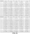
- FIG. 25 shows aspheric parameters pertaining to the optical imaging lens according to the fifth embodiment of the invention.
- FIG. 26 is a schematic diagram illustrating an optical imaging lens according to a sixth embodiment of the invention.
- FIGS. 27A to 27D are diagrams illustrating a longitudinal spherical aberration and various aberrations of the optical imaging lens according to the sixth embodiment.
- FIG. 28 shows detailed optical data of the optical imaging lens according to the sixth embodiment of the invention.
- FIG. 29 shows aspheric parameters pertaining to the optical imaging lens according to the sixth embodiment of the invention.
- FIG. 30 is a schematic diagram illustrating an optical imaging lens according to a seventh embodiment of the invention.
- FIGS. 31A to 31D are diagrams illustrating a longitudinal spherical aberration and various aberrations of the optical imaging lens according to the seventh embodiment.
- FIG. 32 shows detailed optical data of the optical imaging lens according to the seventh embodiment of the invention.
- FIG. 33 shows aspheric parameters pertaining to the optical imaging lens according to the seventh embodiment of the invention.
- FIG. 34 is a schematic diagram illustrating an optical imaging lens according to an eighth embodiment of the invention.
- FIGS. 35A to 35D are diagrams illustrating a longitudinal spherical aberration and various aberrations of the optical imaging lens according to the eighth embodiment.
- FIG. 36 shows detailed optical data of the optical imaging lens according to the eighth embodiment of the invention.
- FIG. 37 shows aspheric parameters pertaining to the optical imaging lens according to the eighth embodiment of the invention.
- FIG. 38 is a schematic diagram illustrating an optical imaging lens according to a ninth embodiment of the invention.
- FIGS. 39A to 39D are diagrams illustrating a longitudinal spherical aberration and various aberrations of the optical imaging lens according to the ninth embodiment.
- FIG. 40 shows detailed optical data of the optical imaging lens according to the ninth embodiment of the invention.
- FIG. 41 shows aspheric parameters pertaining to the optical imaging lens according to the ninth embodiment of the invention.
- FIGS. 42 to 45 show values of respective important parameters and relations thereof of the optical imaging lenses according to the first to ninth embodiments of the invention.
- the optical system may comprise at least one lens element to receive imaging rays that are incident on the optical system over a set of angles ranging from parallel to an optical axis to a half field of view (HFOV) angle with respect to the optical axis.
- the imaging rays pass through the optical system to produce an image on an image plane.
- a lens element having positive refracting power (or negative refracting power) means that the paraxial refracting power of the lens element in Gaussian optics is positive (or negative).
- an object-side (or image-side) surface of a lens element refers to a specific region of that surface of the lens element at which imaging rays can pass through that specific region.
- Imaging rays include at least two types of rays: a chief ray Lc and a marginal ray Lm (as shown in FIG. 1 ).
- An object-side (or image-side) surface of a lens element can be characterized as having several regions, including an optical axis region, a periphery region, and, in some cases, one or more intermediate regions, as discussed more fully below.
- FIG. 1 is a radial cross-sectional view of a lens element 100 .
- Two referential points for the surfaces of the lens element 100 can be defined: a central point, and a transition point.
- the central point of a surface of a lens element is a point of intersection of that surface and the optical axis I.
- a first central point CP 1 may be present on the object-side surface 110 of lens element 100 and a second central point CP 2 may be present on the image-side surface 120 of the lens element 100 .
- the transition point is a point on a surface of a lens element, at which the line tangent to that point is perpendicular to the optical axis I.
- the optical boundary OB of a surface of the lens element is defined as a point at which the radially outermost marginal ray Lm passing through the surface of the lens element intersects the surface of the lens element. All transition points lie between the optical axis I and the optical boundary OB of the surface of the lens element. If multiple transition points are present on a single surface, then these transition points are sequentially named along the radial direction of the surface with reference numerals starting from the first transition point. For example, the first transition point, e.g., TP 1 , (closest to the optical axis I), the second transition point, e.g., TP 2 , (as shown in FIG. 4 ), and the Nth transition point (farthest from the optical axis I).
- the region of a surface of the lens element from the central point to the first transition point TP 1 is defined as the optical axis region, which includes the central point.
- the region located radially outside of the farthest Nth transition point from the optical axis I to the optical boundary OB of the surface of the lens element is defined as the periphery region.
- the shape of a region is convex if a collimated ray being parallel to the optical axis I and passing through the region is bent toward the optical axis I such that the ray intersects the optical axis I on the image side A 2 of the lens element.
- the shape of a region is concave if the extension line of a collimated ray being parallel to the optical axis I and passing through the region intersects the optical axis I on the object side A 1 of the lens element.
- the lens element 100 may also have a mounting portion 130 extending radially outward from the optical boundary OB.
- the mounting portion 130 is typically used to physically secure the lens element to a corresponding element of the optical system (not shown). Imaging rays do not reach the mounting portion 130 .
- the structure and shape of the mounting portion 130 are only examples to explain the technologies, and should not be taken as limiting the scope of the present disclosure.
- the mounting portion 130 of the lens elements discussed below may be partially or completely omitted in the following drawings.
- optical axis region Z 1 is defined between central point CP and first transition point TP 1 .
- Periphery region Z 2 is defined between TP 1 and the optical boundary OB of the surface of the lens element.
- Collimated ray 211 intersects the optical axis I on the image side A 2 of lens element 200 after passing through optical axis region Z 1 , i.e., the focal point of collimated ray 211 after passing through optical axis region Z 1 is on the image side A 2 of the lens element 200 at point R in FIG. 2 . Accordingly, since the ray itself intersects the optical axis I on the image side A 2 of the lens element 200 , optical axis region Z 1 is convex.
- collimated ray 212 diverges after passing through periphery region Z 2 .
- the extension line EL of collimated ray 212 after passing through periphery region Z 2 intersects the optical axis I on the object side A 1 of lens element 200 , i.e., the focal point of collimated ray 212 after passing through periphery region Z 2 is on the object side A 1 at point M in FIG. 2 .
- periphery region Z 2 is concave.
- the first transition point TP 1 is the border of the optical axis region and the periphery region, i.e., TP 1 is the point at which the shape changes from convex to concave.
- R the paraxial radius of shape of a lens surface in the optical axis region.
- the R value is commonly used in conventional optical design software such as Zemax and CodeV.
- the R value usually appears in the lens data sheet in the software.
- a positive R value defines that the optical axis region of the object-side surface is convex
- a negative R value defines that the optical axis region of the object-side surface is concave.
- a positive R value defines that the optical axis region of the image-side surface is concave
- a negative R value defines that the optical axis region of the image-side surface is convex
- FIG. 3 , FIG. 4 and FIG. 5 illustrate examples of determining the shape of lens element regions and the boundaries of regions under various circumstances, including the optical axis region, the periphery region, and intermediate regions as set forth in the present specification.
- FIG. 3 is a radial cross-sectional view of a lens element 300 .
- TP 1 appears within the optical boundary OB of the image-side surface 320 of the lens element 300 .
- Optical axis region Z 1 and periphery region Z 2 of the image-side surface 320 of lens element 300 are illustrated.
- the R value of the image-side surface 320 is positive (i.e., R>0). Accordingly, the optical axis region Z 1 is concave.
- each region demarcated by the transition point will have an opposite shape to the shape of the adjacent region(s). Accordingly, the transition point will define a transition in shape, changing from concave to convex at the transition point or changing from convex to concave.
- the shape of the optical axis region Z 1 is concave
- the shape of the periphery region Z 2 will be convex as the shape changes at the transition point TP 1 .
- FIG. 4 is a radial cross-sectional view of a lens element 400 .
- a first transition point TP 1 and a second transition point TP 2 are present on the object-side surface 410 of lens element 400 .
- the optical axis region Z 1 of the object-side surface 410 is defined between the optical axis I and the first transition point TP 1 .
- the R value of the object-side surface 410 is positive (i.e., R>0). Accordingly, the optical axis region Z 1 is convex.
- the periphery region Z 2 of the object-side surface 410 which is also convex, is defined between the second transition point TP 2 and the optical boundary OB of the object-side surface 410 of the lens element 400 . Further, intermediate region Z 3 of the object-side surface 410 , which is concave, is defined between the first transition point TP 1 and the second transition point TP 2 .
- the object-side surface 410 includes an optical axis region Z 1 located between the optical axis I and the first transition point TP 1 , an intermediate region Z 3 located between the first transition point TP 1 and the second transition point TP 2 , and a periphery region Z 2 located between the second transition point TP 2 and the optical boundary OB of the object-side surface 410 . Since the shape of the optical axis region Z 1 is designed to be convex, the shape of the intermediate region Z 3 is concave as the shape of the intermediate region Z 3 changes at the first transition point TP 1 , and the shape of the periphery region Z 2 is convex as the shape of the periphery region Z 2 changes at the second transition point TP 2 .
- FIG. 5 is a radial cross-sectional view of a lens element 500 .
- Lens element 500 has no transition point on the object-side surface 510 of the lens element 500 .
- the optical axis region Z 1 is defined as the region between 0-50% of the distance between the optical axis I and the optical boundary OB of the surface of the lens element and the periphery region is defined as the region between 50%-100% of the distance between the optical axis I and the optical boundary OB of the surface of the lens element.
- the optical axis region Z 1 of the object-side surface 510 is defined between the optical axis I and 50% of the distance between the optical axis I and the optical boundary OB.
- the R value of the object-side surface 510 is positive (i.e., R>0). Accordingly, the optical axis region Z 1 is convex.
- the periphery region Z 2 of the object-side surface 510 is also convex.
- lens element 500 may have a mounting portion (not shown) extending radially outward from the periphery region Z 2 .
- FIG. 6 is a schematic diagram illustrating an optical imaging lens according to a first embodiment of the invention.
- FIGS. 7A to 7D are diagrams illustrating a longitudinal spherical aberration and various aberrations of the optical imaging lens according to the first embodiment.
- an optical imaging lens 10 includes a first lens element 1 , an aperture 0 , a second lens element 2 , a third lens element 3 , a fourth lens element 4 , a fifth lens element 5 , a sixth lens element 6 , and a filter 9 sequentially arranged from an object side to an image side along an optical axis I.
- an image may be formed on an image plane 99 after the ray passes through the first lens element 1 , the aperture 0 , the second lens element 2 , the third lens element 3 , the fourth lens element 4 , the fifth lens element 5 , the sixth lens element 6 , and the filter 9 .
- the filter 9 may be an infrared cut-off filter, for example, and is adapted to prevent a portion of infrared light in the ray from being transmitted to the image plane 99 and affecting the imaging quality. It is noted that, the object side is a side facing the object to be shot, whereas the image side is a side facing the image plane 99 .
- the first lens element 1 , the second lens element 2 , the third lens element 3 , the fourth lens element 4 , the fifth lens element 5 , the sixth lens element 6 , and the filter 9 respectively have object-side surfaces 15 , 25 , 35 , 45 , 55 , 65 , and 95 facing the object side and allowing imaging rays to pass through and image-side surfaces 16 , 26 , 36 , 46 , 56 , 66 , and 96 facing the image side and allowing the imaging rays to pass through.
- materials of the first lens element 1 to the sixth lens element 6 may be plastic.
- the materials of the first lens element 1 to the sixth lens element 6 are not limited thereto.
- the first lens element 1 has negative refracting power.
- an optical axis region 152 is concave, and a periphery region 153 is convex.
- an optical axis region 162 and a periphery region 164 are both concave.
- the second lens element 2 has positive refracting power.
- an optical axis region 251 and a periphery region 253 are both convex.
- an optical axis region 261 and a periphery region 263 are both convex.
- the third lens element 3 has positive refracting power.
- an optical axis region 352 and a periphery region 354 are both concave.
- an optical axis region 361 and a periphery region 363 are both convex.
- the fourth lens element 4 has negative refracting power.
- an optical axis region 451 is convex, and a periphery region 454 is concave.
- an optical axis region 462 is concave, and a periphery region 463 is convex.
- the fifth lens element 5 has positive refracting power.
- an optical axis region 552 and a periphery region 554 are both concave.
- an optical axis region 561 and a periphery region 563 are both convex.
- the sixth lens element 6 has negative refracting power.
- an optical axis region 651 is convex, and a periphery region 654 is concave.
- an optical axis region 662 is concave, and a periphery region 663 is convex.
- the optical imaging lens 10 only the above lens elements have refracting power, and the number of lens elements having refracting power in the optical imaging lens 10 is six.
- the system length (TTL) of the whole optical imaging lens 10 of the first embodiment is 5,411 mm
- the effective focal length (EFL) thereof is 2,115 mm
- the half field of view (HFOV) thereof is 58,533°
- the image height thereof is 2,880 mm
- the f-number (Fno) thereof is 2,250.
- the system length refers to a distance from the object-side surface 15 of the first lens element 1 to the image plane 99 along the optical axis I.
- the object-side surfaces and the image-side surfaces of the six lens elements, totaling 12 surfaces are all aspheric surfaces.
- the aspheric surfaces are defined based on the following equation:
- Y represents a vertical distance from a point on an aspheric curve to the optical axis I;
- Z represents a depth of an aspheric surface (a vertical distance between the point on the aspheric surface that is spaced by the distance Y from the optical axis I and a tangent plane tangent to a vertex of the aspheric surface on the optical axis I);
- R represents a radius of curvature of the surface of the lens element proximate the optical axis I;
- K represents a conic constant
- a 2i represents a 2i th aspheric coefficient.
- Respective aspheric coefficients of the object-side surfaces 15 , 25 , 35 , 45 , 55 , and 65 and the image-side surfaces 16 , 26 , 36 , 46 , 56 , and 66 in Equation (1) are as shown in FIG. 9 .
- the row number 15 in FIG. 9 indicates the aspheric coefficients of the object-side surface 15 of the first lens element 1 .
- Other rows are arranged based on the same principle.
- V1 is an Abbe number of the first lens element 1 , wherein the Abbe number may also be referred to as a dispersion coefficient;
- V2 is an Abbe number of the second lens element 2 ;
- V3 is an Abbe number of the third lens element 3 ;
- V4 is an Abbe number of the fourth lens element 4 ;
- V5 is an Abbe number of the fifth lens element 5 ;
- V6 is an Abbe number of the sixth lens element 6 ;
- T1 is a thickness of the first lens element 1 along the optical axis I;
- T2 is a thickness of the second lens element 2 along the optical axis I;
- T3 is a thickness of the third lens element 3 along the optical axis I;
- T4 is a thickness of the fourth lens element 4 along the optical axis I;
- T5 is a thickness of the fifth lens element 5 along the optical axis I;
- T6 is a thickness of the sixth lens element 6 along the optical axis I;
- TF is a thickness of the filter 9 along the optical axis I;
- G12 is an air gap from the first lens element 1 to the second lens element 2 along the optical axis I;
- G23 is an air gap from the second lens element 2 to the third lens element 3 along the optical axis I;
- G34 is an air gap from the third lens element 3 to the fourth lens element 4 along the optical axis I;
- G45 is an air gap from the fourth lens element 4 to the fifth lens element 5 along the optical axis I;
- G56 is an air gap from the fifth lens element 5 to the sixth lens element 6 along the optical axis I;
- G6F is an air gap from the sixth lens element 6 to the filter 9 along the optical axis I;
- GFP is an air gap from the filter 9 to the image plane 99 along the optical axis I;
- AAG is a sum of the five air gaps from the first lens element 1 to the sixth lens element 6 along the optical axis I, i.e. the sum of the G12, G23, G34, G45, and G56;
- ALT is a sum of the thicknesses of the first lens element 1 , the second lens element 2 , the third lens element 3 , the fourth lens element 4 , the fifth lens element 5 , and the sixth lens element 6 along the optical axis I, i.e. the sum of the T1, T2, T3, T4, T5, and T6;
- EFL is an effective focal length of the optical imaging lens 10 ;
- BFL is a distance from the image-side surface 66 of the sixth lens element 6 to the image plane 99 along the optical axis I;
- TTL is a distance from the object-side surface 15 of the first lens element 1 to the image plane 99 along the optical axis I;
- TL is a distance from the object-side surface 15 of the first lens element 1 to the image-side surface 66 of the sixth lens element 6 along the optical axis I;
- HFOV is a half field of view of the optical imaging lens 10 .
- FIG. 7A illustrates the longitudinal spherical aberration of optical imaging lens 10 of the first embodiment when the pupil radius is 0.4701 mm.
- the curves representing the respective wavelengths are close to each other and approach the center, indicating that off-axis rays in different heights at the respective wavelengths are concentrated in a vicinity of the imaging point.
- imaging point deviations of the off-axis rays in different heights are controlled within a range from ⁇ 0.04 mm to 0.01 mm. Therefore, the spherical aberration of the same wavelength is reduced in the optical imaging lens of the first embodiment.
- the distances among the three representing wavelengths are close, indicating that imaging positions of rays of different wavelengths are concentrated. Hence, chromatic aberration is also suppressed.
- FIGS. 7B and 7C respectively illustrate the field curvature aberration in the sagittal direction and the field curvature aberration in the tangential direction on the image plane 99 when the wavelength is 650 mm, 555 mm, and 470 mm.
- the field curvature aberrations of the three representing wavelengths in the whole field range fall within a range from ⁇ 0.04 mm to 0.14 mm, indicating that the optical imaging lens of the first embodiment is able to effectively reduce aberration.
- FIG. 7D illustrates the distortion aberration on the image plane 99 when the wavelength is 650 mm, 555 mm, and 470 mm.
- FIG. 7D illustrating the distortion aberration indicates that the distortion aberration is maintained within a range from ⁇ 18% to 3%, indicating that the distortion aberration of the optical imaging lens of the first embodiment already satisfies the imaging quality requirement of an optical system.
- the optical imaging lens of the first embodiment is able to render a desirable imaging quality under a condition that the system length is reduced to about 5,411 mm. Besides, in the optical imaging lens of the first embodiment, the system length is reduced and the shooting angle is expanded under a condition of maintaining a desirable optical performance. Thus, a product design capable of miniaturization and expanding the field of view is achieved.
- FIG. 10 is a schematic diagram illustrating an optical imaging lens according to a second embodiment of the invention.
- FIGS. 11A to 11D are diagrams illustrating a longitudinal spherical aberration and various aberrations of the optical imaging lens according to the second embodiment.
- the second embodiment of the optical imaging lens 10 is similar to the first embodiment, and the differences therebetween mainly include the following: respective optical data, aspheric coefficients and parameters among the lens elements are different to a more or lesser extent.
- a periphery region 564 of the image-side surface 56 of the fifth lens element 5 is concave.
- some reference numerals indicating surface shapes same as those of the first embodiment are omitted in FIG. 10 .
- the system length (TTL) of the optical imaging lens 10 of the second embodiment is 4,865 mm
- the effective focal length (EFL) thereof is 2,497 mm
- the half field of view (HFOV) thereof is 58.439°
- the image height thereof is 2,880 mm
- the f-number (Fno) thereof is 2.250.
- relations of important parameters in the optical imaging lens 10 according to the second embodiment are as shown in FIGS. 42 and 43 .
- FIGS. 11A to 11D in FIG. 11A illustrating the longitudinal spherical aberration, imaging point deviations of the off-axis rays in different heights are controlled within ⁇ 0.02 mm to 0.14 mm when the pupil radius is 0.5548 mm.
- FIGS. 11B and 11C illustrating the field curvature aberrations the field curvature aberrations of the three representing wavelengths in the whole field range fall within a range from ⁇ 0.60 mm to 0.14 mm.
- FIG. 11D illustrating the distortion aberration the distortion aberration is maintained within a range from ⁇ 25% to 0%.
- the optical imaging lens 10 of the second embodiment is able to render a desirable imaging quality under a condition that the system length is reduced to about 4,865 mm.
- the second embodiment is more desirable over the first embodiment in that the system length of the second embodiment is less than that of the first embodiment. Besides, because a thickness difference between the optical axis regions and the periphery regions of the lens elements in the second embodiment is less than that of the first embodiment, the lens elements in the second embodiment are easier to be manufactured and thus have higher yield.
- FIG. 14 is a schematic diagram illustrating an optical imaging lens according to a third embodiment of the invention.
- FIGS. 15A to 15D are diagrams illustrating a longitudinal spherical aberration and various aberrations of the optical imaging lens according to the third embodiment.
- the third embodiment of the optical imaging lens 10 is similar to the first embodiment, and the differences therebetween mainly include the following: respective optical data, aspheric coefficients and parameters among the lens elements are different to a more or lesser extent.
- a periphery region 564 of the image-side surface 56 of the fifth lens element 5 is concave. To clearly illustrate the drawing, some reference numerals indicating surface shapes same as those of the first embodiment are omitted in FIG. 14 .
- the system length (TTL) of the optical imaging lens 10 of the third embodiment is 5,600 mm
- the effective focal length (EFL) thereof is 2,173 mm
- the half field of view (HFOV) thereof is 58.459°
- the image height thereof is 2,880 mm
- the f-number (Fno) thereof is 2.250.
- relations of important parameters in the optical imaging lens 10 according to the third embodiment are as shown in FIGS. 42 and 43 .
- FIGS. 15A to 15D in FIG. 15A illustrating the longitudinal spherical aberration, imaging point deviations of the off-axis rays in different heights are controlled within ⁇ 0.045 mm to 0.025 mm when the pupil radius is 0.4828 mm.
- FIGS. 15B and 15C illustrating the field curvature aberrations the field curvature aberrations of the three representing wavelengths in the whole field range fall within a range from ⁇ 0.08 mm to 0.06 mm.
- FIG. 15D illustrating the distortion aberration the distortion aberration is maintained within a range from ⁇ 20% to 4%.
- the optical imaging lens 10 of the third embodiment is able to render a desirable imaging quality under a condition that the system length is reduced to about 5,600 mm.
- the third embodiment is more desirable over the first embodiment in that the field curvature aberration of the third embodiment is less than that of the first embodiment. Besides, because a thickness difference between the optical axis regions and the periphery regions of the lens elements in the third embodiment is less than that of the first embodiment, the lens elements in the third embodiment are easier to be manufactured and thus have higher yield.
- FIG. 18 is a schematic diagram illustrating an optical imaging lens according to a fourth embodiment of the invention.
- FIGS. 19A to 19D are diagrams illustrating a longitudinal spherical aberration and various aberrations of the optical imaging lens according to the fourth embodiment.
- the fourth embodiment of the optical imaging lens 10 is similar to the first embodiment, and the differences therebetween mainly include the following: respective optical data, aspheric coefficients and parameters among the lens elements are different to a more or lesser extent.
- a periphery region 464 of the image-side surface 46 of the fourth lens element 4 is concave
- a periphery region 553 of the object-side surface 55 of the fifth lens element 5 is convex.
- some reference numerals indicating surface shapes same as those of the first embodiment are omitted in FIG. 18 .
- the system length (TTL) of the optical imaging lens 10 of the fourth embodiment is 5,014 mm
- the effective focal length (EFL) thereof is 2,157 mm
- the half field of view (HFOV) thereof is 58.520°
- the image height thereof is 2,880 mm
- the f-number (Fno) thereof is 2.250.
- relations of important parameters in the optical imaging lens 10 according to the fourth embodiment are as shown in FIGS. 42 and 43 .
- FIGS. 19A to 19D in FIG. 19A illustrating the longitudinal spherical aberration, imaging point deviations of the off-axis rays in different heights are controlled within ⁇ 0.035 mm to 0.015 mm when the pupil radius is 0.4793 mm.
- FIGS. 19B and 19C illustrating the field curvature aberrations the field curvature aberrations of the three representing wavelengths in the whole field range fall within a range from ⁇ 0.07 mm to 0.06 mm.
- FIG. 19D illustrating the distortion aberration the distortion aberration is maintained within a range from ⁇ 20% to 1%. Based on the above, compared with known optical lenses, the optical imaging lens 10 of the fourth embodiment is able to render a desirable imaging quality under a condition that the system length is reduced to about 5,014 mm.
- the fourth embodiment is more desirable over the first embodiment in that the system length of the fourth embodiment is less than that of the first embodiment.
- the longitudinal spherical aberration, the field curvature aberration, and the distortion aberration of the fourth embodiment are respectively less than the longitudinal spherical aberration, the field curvature aberration, and the distortion aberration of the first embodiment.
- the lens elements in the fourth embodiment are easier to be manufactured and thus have higher yield.
- FIG. 22 is a schematic diagram illustrating an optical imaging lens according to a fifth embodiment of the invention.
- FIGS. 23A to 23D are diagrams illustrating a longitudinal spherical aberration and various aberrations of the optical imaging lens according to the fifth embodiment.
- the fifth embodiment of the optical imaging lens 10 is similar to the first embodiment, and the differences therebetween mainly include the following: respective optical data, aspheric coefficients and parameters among the lens elements are different to a more or lesser extent.
- the third lens element 3 has negative refracting power.
- the periphery region 464 of the image-side surface 46 of the fourth lens element 4 is concave.
- the periphery region 553 of the object-side surface 55 of the fifth lens element 5 is convex.
- some reference numerals indicating surface shapes same as those of the first embodiment are omitted in FIG. 22 .
- the system length (TTL) of the optical imaging lens 10 of the fifth embodiment is 4,790 mm
- the effective focal length (EFL) thereof is 2,117 mm
- the half field of view (HFOV) thereof is 58.438°
- the image height thereof is 2,880 mm
- the f-number (Fno) thereof is 2.250.
- relations of important parameters in the optical imaging lens 10 according to the fifth embodiment are as shown in FIGS. 42 and 43 .
- FIGS. 23A to 23D in FIG. 23A illustrating the longitudinal spherical aberration, imaging point deviations of the off-axis rays in different heights are controlled within ⁇ 0.03 mm to 0.015 mm when the pupil radius is 0.4704 mm.
- FIGS. 23B and 23C illustrating the field curvature aberrations
- the field curvature aberrations of the three representing wavelengths in the whole field range fall within a range from ⁇ 0.12 mm to 0.04 mm.
- FIG. 23D illustrating the distortion aberration the distortion aberration is maintained within a range from ⁇ 18% to 0%.
- the optical imaging lens 10 of the fifth embodiment is able to render a desirable imaging quality under a condition that the system length is reduced to about 4,790 mm.
- the fifth embodiment is more desirable over the first embodiment in that the system length of the fifth embodiment is less than that of the first embodiment.
- the longitudinal spherical aberration, the field curvature aberration, and the distortion aberration of the fifth embodiment are respectively less than the longitudinal spherical aberration, the field curvature aberration, and the distortion aberration of the first embodiment.
- the lens elements in the fifth embodiment are easier to be manufactured and thus have higher yield.
- FIG. 26 is a schematic diagram illustrating an optical imaging lens according to a sixth embodiment of the invention.
- FIGS. 27A to 27D are diagrams illustrating a longitudinal spherical aberration and various aberrations of the optical imaging lens according to the sixth embodiment.
- the sixth embodiment of the optical imaging lens 10 is similar to the first embodiment, and the differences therebetween mainly include the following: respective optical data, aspheric coefficients and parameters among the lens elements are different to a more or lesser extent.
- some reference numerals indicating surface shapes same as those of the first embodiment are omitted in FIG. 26 .
- the system length (TTL) of the optical imaging lens 10 of the sixth embodiment is 5,035 mm
- the effective focal length (EFL) thereof is 2,086 mm
- the half field of view (HFOV) thereof is 58.519°
- the image height thereof is 2,880 mm
- the f-number (Fno) thereof is 2.250.
- relations of important parameters in the optical imaging lens 10 according to the sixth embodiment are as shown in FIGS. 44 and 45 .
- FIGS. 27A to 27D in FIG. 27A illustrating the longitudinal spherical aberration, imaging point deviations of the off-axis rays in different heights are controlled within ⁇ 0.07 mm to 0.02 mm when the pupil radius is 0.4634 mm.
- FIGS. 27B and 27C illustrating the field curvature aberrations the field curvature aberrations of the three representing wavelengths in the whole field range fall within a range from ⁇ 0.13 mm to 0.05 mm.
- FIG. 27D illustrating the distortion aberration the distortion aberration is maintained within a range from ⁇ 18% to 2%.
- the optical imaging lens 10 of the sixth embodiment is able to render a desirable imaging quality under a condition that the system length is reduced to about 5,035 mm.
- the sixth embodiment is more desirable over the first embodiment in that the system length of the sixth embodiment is less than that of the first embodiment.
- the field curvature aberration and the distortion aberration of the sixth embodiment are respectively less than the field curvature aberration and the distortion aberration of the first embodiment.
- the lens elements in the sixth embodiment are easier to be manufactured and thus have higher yield.
- FIG. 30 is a schematic diagram illustrating an optical imaging lens according to a seventh embodiment of the invention.
- FIGS. 31A to 31D are diagrams illustrating a longitudinal spherical aberration and various aberrations of the optical imaging lens according to the seventh embodiment.
- the seventh embodiment of the optical imaging lens 10 is similar to the first embodiment, and the differences therebetween mainly include the following: respective optical data, aspheric coefficients and parameters among the lens elements are different to a more or lesser extent.
- an optical axis region 151 of the object-side surface 15 of the first lens element 1 is convex.
- a periphery region 353 of the object-side surface 35 of the third lens element 3 is convex.
- the periphery region 464 of the image-side surface 46 of the fourth lens element 4 is concave.
- some reference numerals indicating surface shapes same as those of the first embodiment are omitted in FIG. 30 .
- the system length (TTL) of the optical imaging lens 10 of the seventh embodiment is 4,673 mm
- the effective focal length (EFL) thereof is 2,285 mm
- the half field of view (HFOV) thereof is 58.520°
- the image height thereof is 2,880 mm
- the f-number (Fno) thereof is 2.250.
- relations of important parameters in the optical imaging lens 10 according to the seventh embodiment are as shown in FIGS. 44 and 45 .
- FIGS. 31A to 31D in FIG. 31A illustrating the longitudinal spherical aberration, imaging point deviations of the off-axis rays in different heights are controlled within ⁇ 0.02 mm to 0.012 mm when the pupil radius is 0.5078 mm.
- FIGS. 31B and 31C illustrating the field curvature aberrations
- the field curvature aberrations of the three representing wavelengths in the whole field range fall within a range from ⁇ 0.30 mm to 0.10 mm.
- FIG. 31D illustrating the distortion aberration
- the distortion aberration is maintained within a range from ⁇ 25% to 0%.
- the optical imaging lens 10 of the seventh embodiment is able to render a desirable imaging quality under a condition that the system length is reduced to about 4,673 mm.
- the seventh embodiment is more desirable over the first embodiment in that the system length of the seventh embodiment is less than that of the first embodiment.
- the longitudinal spherical aberration of the seventh embodiment is less than the longitudinal spherical aberration of the first embodiment.
- the lens elements in the seventh embodiment are easier to be manufactured and thus have higher yield.
- FIG. 34 is a schematic diagram illustrating an optical imaging lens according to an eighth embodiment of the invention.
- FIGS. 35A to 35D are diagrams illustrating a longitudinal spherical aberration and various aberrations of the optical imaging lens according to the eighth embodiment.
- the eighth embodiment of the optical imaging lens 10 is similar to the first embodiment, and the differences therebetween mainly include the following: respective optical data, aspheric coefficients and parameters among the lens elements are different to a more or lesser extent.
- a periphery region 464 of the image-side surface 46 of the fourth lens element 4 is concave
- a periphery region 553 of the object-side surface 55 of the fifth lens element 5 is convex.
- some reference numerals indicating surface shapes same as those of the first embodiment are omitted in FIG. 34 .
- the system length (TTL) of the optical imaging lens 10 of the eighth embodiment is 5,052 mm
- the effective focal length (EFL) thereof is 2,202 mm
- the half field of view (HFOV) thereof is 58.521°
- the image height thereof is 2,880 mm
- the f-number (Fno) thereof is 2.250.
- FIGS. 35A to 35D in FIG. 35A illustrating the longitudinal spherical aberration, imaging point deviations of the off-axis rays in different heights are controlled within ⁇ 0.025 mm to 0.015 mm when the pupil radius is 0.4892 mm.
- FIGS. 35B and 35C illustrating the field curvature aberrations the field curvature aberrations of the three representing wavelengths in the whole field range fall within a range from ⁇ 0.08 mm to 0.10 mm.
- FIG. 35D illustrating the distortion aberration the distortion aberration is maintained within a range from ⁇ 21% to 0%. Based on the above, compared with known optical lenses, the optical imaging lens 10 of the eighth embodiment is able to render a desirable imaging quality under a condition that the system length is reduced to about 5,052 mm.
- the eighth embodiment is more desirable over the first embodiment in that the system length of the eighth embodiment is less than that of the first embodiment. Besides, because a thickness difference between the optical axis regions and the periphery regions of the lens elements in the eighth embodiment is less than that of the first embodiment, the lens elements in the eighth embodiment are easier to be manufactured and thus have higher yield.
- FIG. 38 is a schematic diagram illustrating an optical imaging lens according to a ninth embodiment of the invention.
- FIGS. 39A to 39D are diagrams illustrating a longitudinal spherical aberration and various aberrations of the optical imaging lens according to the ninth embodiment.
- the ninth embodiment of the optical imaging lens 10 is similar to the first embodiment, and the differences therebetween mainly include the following: respective optical data, aspheric coefficients and parameters among the lens elements are different to a more or lesser extent.
- a periphery region 464 of the image-side surface 46 of the fourth lens element 4 is concave
- a periphery region 553 of the object-side surface 55 of the fifth lens element 5 is convex.
- some reference numerals indicating surface shapes same as those of the first embodiment are omitted in FIG. 38 .
- the system length (TTL) of the optical imaging lens 10 of the ninth embodiment is 4,913 mm
- the effective focal length (EFL) thereof is 2,247 mm
- the half field of view (HFOV) thereof is 58.522°
- the image height thereof is 2,880 mm
- the f-number (Fno) thereof is 2.250.
- FIGS. 39A to 39D in FIG. 39A illustrating the longitudinal spherical aberration, imaging point deviations of the off-axis rays in different heights are controlled within ⁇ 0.05 mm to 0.02 mm when the pupil radius is 0.4993 mm.
- FIGS. 39B and 39C illustrating the field curvature aberrations
- the field curvature aberrations of the three representing wavelengths in the whole field range fall within a range from ⁇ 0.06 mm to 0.08 mm.
- FIG. 39D illustrating the distortion aberration
- the distortion aberration is maintained within a range from ⁇ 25% to 0%.
- the optical imaging lens 10 of the ninth embodiment is able to render a desirable imaging quality under a condition that the system length is reduced to about 4,913 mm.
- the ninth embodiment is more desirable over the first embodiment in that the system length of the ninth embodiment is less than that of the first embodiment.
- the field curvature aberration of the ninth embodiment is less than the field curvature aberration of the first embodiment.
- the lens elements in the ninth embodiment are easier to be manufactured and thus have higher yield.
- light can be effectively converged as the optical axis region of the image-side surface of the second lens element is convex, and in coordination with that the optical axis region of the object-side surface of the third lens element is concave.
- the optical axis region of the object-side surface of the fifth lens element is concave, the fifth lens element has positive refracting power, and in coordination with that the optical axis region of the object side surface of the fourth lens element is convex or AAG/T4 ⁇ 5.0 or AAG/T5 ⁇ 1.8, it is beneficial for the correction of the aberrations under a premise that a greater field of view is provided.
- a preferable range of AAG/T4 is 3,000 to 5,000, and a preferable range of AAG/T5 is 0.900 to 1,800.
- V3 ⁇ V6 ⁇ 20,000 is satisfied, the system length can be reduced and the imaging quality can be ensured, wherein a preferable range of V3-V6 is 20,000 to 40,000.
- the air gap between lens elements or the thickness of the lens element may be suitably reduced. Nevertheless, considering the manufacturing complexity, a configuration is desirable if at least one of the following condition expressions is satisfied. 3,600 ⁇ ( T 1+ G 12)/( G 23+ G 34+ G 56), preferably 3,600 ⁇ ( T 1+ G 12)/( G 23+ G 34+ G 56) ⁇ 5,700; 4,600 ⁇ EFL/( T 3+ G 56), preferably 4,600 ⁇ EFL/( T 3+ G 56) ⁇ 6,800; AAG/ T 2 ⁇ 4,000, preferably 1,600 ⁇ AAG/ T 2 ⁇ 4,000; 3,700 ⁇ ALT/( T 4+ G 56), preferably 3,700 ⁇ ALT/( T 4+ G 56) ⁇ 10,000; 10,200 ⁇ ALT/( G 23+ G 34+ G 56), preferably 10,200 ⁇ ALT/( G 23+ G 34+ G 56) ⁇ 18,200; AAG/ G 45 ⁇ 6,000, preferably 2,900 ⁇ AAG/ G 45 ⁇ 6,000; EFL/ T 5 ⁇ 4,200
- the ratio of the optical element parameters to the system length is maintained to be within an appropriate range, so as to prevent the optical element parameters from becoming too small, which is detrimental to the production of the optical imaging lens, or to prevent the optical element parameters from becoming too large, which may lead to excessive system length TTL/( T 1+ T 5) ⁇ 4,800, preferably 3,900 ⁇ TTL/( T 1+ T 5) ⁇ 4,800; TTL /T 5 ⁇ 7,800, preferably 5,300 ⁇ TTL /T 5 ⁇ 7,800; TTL/( T 5+ T 6) ⁇ 6,000, preferably 3,200 ⁇ TTL/( T 5+ T 6) ⁇ 6,000; 13,800 ⁇ TTL/( T 4+ G 56), preferably 13,800 ⁇ TTL/( T 4+ G 56) ⁇ 17,000; TL/( T 1+ T 5) ⁇ 4,100, preferably 2,900 ⁇ TL/( T 1+ T 5) ⁇ 4,100; TTL/( T 2+ T 6) ⁇ 5,100, preferably 4,400 ⁇ TTL/(
- the embodiments of the invention may have shorter system length, greater aperture availability, desirable imaging quality, or a facilitated assembling yield rate if the above condition expressions are satisfied so as to improve the shortcoming of prior art.
- the optical imaging lens is able to render one or some of the following:
- the longitudinal spherical aberrations, field curvature aberrations, and distortion aberrations of the respective embodiments of the invention meet the protocol of use.
- the off-axis rays of the three representing wavelengths, i.e., 650 nm, 555 nm, and 470 nm, in different heights are all concentrated at a vicinity of the imaging point.
- the extents of deviation of the respective curves show that the imaging point deviations of the off-axis rays in different heights are controlled, so a desirable suppressing ability against spherical aberration, image aberration, and distortion aberration is rendered.
- the imaging quality data further suggest that the distances among the three representing wavelengths, i.e., 650 nm, 555 nm, and 470 nm, are close to each other, indicating that the embodiments of the invention are able to desirably concentrate rays of different wavelengths in various states and exhibit an excellent dispersion suppressing ability. Therefore, the embodiments of the invention render a desirable optical performance.
Landscapes
- Physics & Mathematics (AREA)
- General Physics & Mathematics (AREA)
- Optics & Photonics (AREA)
- Lenses (AREA)
Abstract
Description
3,600≤(T1+G12)/(G23+G34+G56), preferably
3,600≤(T1+G12)/(G23+G34+G56)≤5,700;
4,600≤EFL/(T3+G56), preferably 4,600≤EFL/(T3+G56)≤6,800;
AAG/T2≤4,000, preferably 1,600≤AAG/T2≤4,000;
3,700≤ALT/(T4+G56), preferably 3,700≤ALT/(T4+G56)≤10,000;
10,200≤ALT/(G23+G34+G56), preferably 10,200≤ALT/(G23+G34+G56)≤18,200;
AAG/G45≤6,000, preferably 2,900≤AAG/G45≤6,000;
EFL/T5≤4,200, preferably 2,200≤EFL/T5≤4,200;
3,100≤BFL/T3, preferably 3,100≤BFL/T3≤6,000;
4,500≤(G12+T5)/(G23+G34+G56), preferably
4,500≤(G12+T5)/(G23+G34+G56)≤9,000; and
6,200≤ALT/(T3+G56), preferably 6,200≤ALT/(T3+G56)≤9,300.
TTL/(T1+T5)≤4,800, preferably 3,900≤TTL/(T1+T5)≤4,800;
TTL/T5≤7,800, preferably 5,300≤TTL/T5≤7,800;
TTL/(T5+T6)≤6,000, preferably 3,200≤TTL/(T5+T6)≤6,000;
13,800≤TTL/(T4+G56), preferably 13,800≤TTL/(T4+G56)≤17,000;
TL/(T1+T5)≤4,100, preferably 2,900≤TL/(T1+T5)≤4,100;
TTL/(T2+T6)≤5,100, preferably 4,400≤TTL/(T2+T6)≤5,100; and
TL/(T3+T5)≤4,000, preferably 3,000≤TL/(T3+T5)≤4,000.
Claims (19)
Priority Applications (1)
| Application Number | Priority Date | Filing Date | Title |
|---|---|---|---|
| US17/143,156 US11586010B2 (en) | 2018-03-30 | 2021-01-07 | Optical imaging lens |
Applications Claiming Priority (3)
| Application Number | Priority Date | Filing Date | Title |
|---|---|---|---|
| CN201810294461.2 | 2018-03-30 | ||
| CN201810294461.2A CN108508578B (en) | 2018-03-30 | 2018-03-30 | Optical imaging lens |
| CN201810294461 | 2018-03-30 |
Related Child Applications (1)
| Application Number | Title | Priority Date | Filing Date |
|---|---|---|---|
| US17/143,156 Continuation US11586010B2 (en) | 2018-03-30 | 2021-01-07 | Optical imaging lens |
Publications (2)
| Publication Number | Publication Date |
|---|---|
| US20190302410A1 US20190302410A1 (en) | 2019-10-03 |
| US10921555B2 true US10921555B2 (en) | 2021-02-16 |
Family
ID=63380084
Family Applications (2)
| Application Number | Title | Priority Date | Filing Date |
|---|---|---|---|
| US16/015,191 Active 2039-03-02 US10921555B2 (en) | 2018-03-30 | 2018-06-22 | Optical imaging lens |
| US17/143,156 Active 2039-02-17 US11586010B2 (en) | 2018-03-30 | 2021-01-07 | Optical imaging lens |
Family Applications After (1)
| Application Number | Title | Priority Date | Filing Date |
|---|---|---|---|
| US17/143,156 Active 2039-02-17 US11586010B2 (en) | 2018-03-30 | 2021-01-07 | Optical imaging lens |
Country Status (3)
| Country | Link |
|---|---|
| US (2) | US10921555B2 (en) |
| CN (3) | CN118330846A (en) |
| TW (1) | TWI664464B (en) |
Families Citing this family (16)
| Publication number | Priority date | Publication date | Assignee | Title |
|---|---|---|---|---|
| JP2021086075A (en) * | 2019-11-29 | 2021-06-03 | コニカミノルタ株式会社 | Image capturing optical system, image capturing device, and portable terminal |
| CN111142218B (en) * | 2019-12-16 | 2021-09-24 | 诚瑞光学(常州)股份有限公司 | Camera optics |
| CN111077648B (en) * | 2019-12-23 | 2021-12-14 | 诚瑞光学(常州)股份有限公司 | Camera optics |
| CN111007647B (en) * | 2019-12-27 | 2021-12-14 | 诚瑞光学(常州)股份有限公司 | Camera optics |
| CN111025579B (en) * | 2019-12-27 | 2021-12-14 | 诚瑞光学(常州)股份有限公司 | Camera optics |
| CN110908086B (en) * | 2019-12-27 | 2022-02-08 | 诚瑞光学(常州)股份有限公司 | Image pickup optical lens |
| CN111007648B (en) * | 2019-12-27 | 2021-10-29 | 诚瑞光学(常州)股份有限公司 | Camera optics |
| CN111007649B (en) * | 2019-12-27 | 2021-09-24 | 诚瑞光学(常州)股份有限公司 | Camera optics |
| TWI724919B (en) * | 2020-06-11 | 2021-04-11 | 新鉅科技股份有限公司 | Six-piece optical lens system with a wide field of view |
| JP7519849B2 (en) | 2020-09-09 | 2024-07-22 | 東京晨美光学電子株式会社 | Imaging lens |
| CN116360069B (en) * | 2020-09-24 | 2026-03-10 | 玉晶光电(厦门)有限公司 | Optical lens group |
| KR20220063682A (en) * | 2020-11-10 | 2022-05-17 | (주)코아시아옵틱스 | Optical imaging system comprising composite lens surface and imaging device comprising the same, and method of designing composite lens surface |
| CN113866945B (en) * | 2021-09-30 | 2024-07-19 | 玉晶光电(厦门)有限公司 | Optical imaging lens |
| CN115963620B (en) * | 2021-10-12 | 2025-09-26 | 宁波舜宇车载光学技术有限公司 | Optical lenses and electronic devices |
| CN119087628A (en) * | 2022-01-12 | 2024-12-06 | 玉晶光电(厦门)有限公司 | Optical imaging lens |
| TWI792901B (en) * | 2022-01-28 | 2023-02-11 | 新鉅科技股份有限公司 | Optical lens assembly and photographing module |
Citations (4)
| Publication number | Priority date | Publication date | Assignee | Title |
|---|---|---|---|---|
| US20140092491A1 (en) * | 2012-10-02 | 2014-04-03 | Largan Precision Co., Ltd. | Imaging lens assembly |
| US20150131169A1 (en) * | 2012-07-23 | 2015-05-14 | Fujifilm Corporation | Imaging lens and imaging apparatus |
| US20170269342A1 (en) * | 2016-03-18 | 2017-09-21 | Ace Solutech Co., Ltd. | Super wide-angle lens and imaging device including the same |
| US20180136443A1 (en) * | 2016-04-01 | 2018-05-17 | Zhejiang Sunny Optics Co., Ltd. | Camera lens |
Family Cites Families (15)
| Publication number | Priority date | Publication date | Assignee | Title |
|---|---|---|---|---|
| TWI437258B (en) * | 2011-08-05 | 2014-05-11 | Largan Precision Co Ltd | Optical lens assembly for image taking |
| TWI452332B (en) * | 2012-08-08 | 2014-09-11 | Largan Precision Co Ltd | Optical photographing lens system |
| TWI451121B (en) * | 2013-02-08 | 2014-09-01 | Newmax Technology Co Ltd | Six-piece optical lens system |
| JP2014240918A (en) * | 2013-06-12 | 2014-12-25 | 富士フイルム株式会社 | Imaging lens and imaging apparatus including imaging lens |
| CN103777329B (en) * | 2013-10-31 | 2016-05-11 | 玉晶光电(厦门)有限公司 | Optical imaging lens and apply the electronic installation of this optical imaging lens |
| JP2015125150A (en) * | 2013-12-25 | 2015-07-06 | 富士フイルム株式会社 | Image-capturing lens and image-capturing device |
| TWI479190B (en) * | 2014-03-24 | 2015-04-01 | Largan Precision Co Ltd | Imaging lens assembly, imaging device and vehicle photographing device |
| TWI484214B (en) * | 2014-06-17 | 2015-05-11 | 玉晶光電股份有限公司 | Portable electronic device and optical imaging lens thereof |
| CN105717609B (en) * | 2014-12-05 | 2018-05-25 | 大立光电股份有限公司 | Optical image-taking lens group, image-taking device and electronic device |
| KR101820952B1 (en) * | 2015-03-11 | 2018-03-09 | 에이에이씨 어쿠스틱 테크놀로지스(심천)컴퍼니 리미티드 | Imaging Lens System |
| KR101823203B1 (en) * | 2015-08-10 | 2018-01-29 | 삼성전기주식회사 | Imaging Lens System |
| TWI580999B (en) * | 2016-05-20 | 2017-05-01 | 大立光電股份有限公司 | Image capturing lens assembly, imaging apparatus and electronic device |
| TWI610090B (en) * | 2016-06-16 | 2018-01-01 | 大立光電股份有限公司 | Optical image lens assembly, image capturing device and electronic device |
| CN106019535B (en) * | 2016-07-12 | 2017-11-14 | 浙江舜宇光学有限公司 | Pick-up lens |
| JP6178944B1 (en) * | 2017-05-12 | 2017-08-09 | エーエーシーアコースティックテクノロジーズ(シンセン)カンパニーリミテッドAAC Acoustic Technologies(Shenzhen)Co., Ltd | Imaging lens |
-
2018
- 2018-03-30 CN CN202410397517.2A patent/CN118330846A/en active Pending
- 2018-03-30 CN CN202010086126.0A patent/CN111273425B/en active Active
- 2018-03-30 CN CN201810294461.2A patent/CN108508578B/en active Active
- 2018-04-18 TW TW107113162A patent/TWI664464B/en active
- 2018-06-22 US US16/015,191 patent/US10921555B2/en active Active
-
2021
- 2021-01-07 US US17/143,156 patent/US11586010B2/en active Active
Patent Citations (4)
| Publication number | Priority date | Publication date | Assignee | Title |
|---|---|---|---|---|
| US20150131169A1 (en) * | 2012-07-23 | 2015-05-14 | Fujifilm Corporation | Imaging lens and imaging apparatus |
| US20140092491A1 (en) * | 2012-10-02 | 2014-04-03 | Largan Precision Co., Ltd. | Imaging lens assembly |
| US20170269342A1 (en) * | 2016-03-18 | 2017-09-21 | Ace Solutech Co., Ltd. | Super wide-angle lens and imaging device including the same |
| US20180136443A1 (en) * | 2016-04-01 | 2018-05-17 | Zhejiang Sunny Optics Co., Ltd. | Camera lens |
Also Published As
| Publication number | Publication date |
|---|---|
| US20210191078A1 (en) | 2021-06-24 |
| TW201839444A (en) | 2018-11-01 |
| TWI664464B (en) | 2019-07-01 |
| US20190302410A1 (en) | 2019-10-03 |
| CN108508578A (en) | 2018-09-07 |
| US11586010B2 (en) | 2023-02-21 |
| CN108508578B (en) | 2020-03-17 |
| CN111273425B (en) | 2024-06-18 |
| CN111273425A (en) | 2020-06-12 |
| CN118330846A (en) | 2024-07-12 |
Similar Documents
| Publication | Publication Date | Title |
|---|---|---|
| US11586010B2 (en) | Optical imaging lens | |
| US11586021B2 (en) | Optical imaging lens | |
| US12147018B2 (en) | Optical imaging lens | |
| US11054616B2 (en) | Optical imaging lens | |
| US10732387B2 (en) | Optical imaging lens | |
| US10175457B2 (en) | Optical imaging lens | |
| US10459204B2 (en) | Optical imaging lens | |
| US10962744B2 (en) | Optical lens assembly | |
| US10606043B2 (en) | Optical imaging lens | |
| US20180067283A1 (en) | Optical imaging lens | |
| US10466443B2 (en) | Optical imaging lens | |
| US10884220B2 (en) | Optical imaging lens | |
| US11385443B2 (en) | Optical imaging lens | |
| US11002942B2 (en) | Optical imaging lens | |
| US11435553B2 (en) | Optical imaging lens | |
| US11835684B2 (en) | Optical imaging lens | |
| US11125982B2 (en) | Optical imaging lens | |
| US11867974B2 (en) | Optical imaging lens |
Legal Events
| Date | Code | Title | Description |
|---|---|---|---|
| AS | Assignment |
Owner name: GENIUS ELECTRONIC OPTICAL (XIAMEN) CO., LTD., CHIN Free format text: ASSIGNMENT OF ASSIGNORS INTEREST;ASSIGNORS:CHEN, FENG;YIN, YANXUAN;FAN, TA-CHENG;REEL/FRAME:046171/0476 Effective date: 20180425 Owner name: GENIUS ELECTRONIC OPTICAL (XIAMEN) CO., LTD., CHINA Free format text: ASSIGNMENT OF ASSIGNORS INTEREST;ASSIGNORS:CHEN, FENG;YIN, YANXUAN;FAN, TA-CHENG;REEL/FRAME:046171/0476 Effective date: 20180425 |
|
| FEPP | Fee payment procedure |
Free format text: ENTITY STATUS SET TO UNDISCOUNTED (ORIGINAL EVENT CODE: BIG.); ENTITY STATUS OF PATENT OWNER: LARGE ENTITY |
|
| STCF | Information on status: patent grant |
Free format text: PATENTED CASE |
|
| MAFP | Maintenance fee payment |
Free format text: PAYMENT OF MAINTENANCE FEE, 4TH YEAR, LARGE ENTITY (ORIGINAL EVENT CODE: M1551); ENTITY STATUS OF PATENT OWNER: LARGE ENTITY Year of fee payment: 4 |