US10914357B2 - Multi-axis reaction system and method for vibration control of mechanical systems - Google Patents
Multi-axis reaction system and method for vibration control of mechanical systems Download PDFInfo
- Publication number
- US10914357B2 US10914357B2 US15/433,325 US201715433325A US10914357B2 US 10914357 B2 US10914357 B2 US 10914357B2 US 201715433325 A US201715433325 A US 201715433325A US 10914357 B2 US10914357 B2 US 10914357B2
- Authority
- US
- United States
- Prior art keywords
- eccentric masses
- motors
- rotation
- platform
- axis
- Prior art date
- Legal status (The legal status is an assumption and is not a legal conclusion. Google has not performed a legal analysis and makes no representation as to the accuracy of the status listed.)
- Active, expires
Links
Images


Classifications
-
- F—MECHANICAL ENGINEERING; LIGHTING; HEATING; WEAPONS; BLASTING
- F16—ENGINEERING ELEMENTS AND UNITS; GENERAL MEASURES FOR PRODUCING AND MAINTAINING EFFECTIVE FUNCTIONING OF MACHINES OR INSTALLATIONS; THERMAL INSULATION IN GENERAL
- F16F—SPRINGS; SHOCK-ABSORBERS; MEANS FOR DAMPING VIBRATION
- F16F15/00—Suppression of vibrations in systems; Means or arrangements for avoiding or reducing out-of-balance forces, e.g. due to motion
- F16F15/22—Compensation of inertia forces
- F16F15/223—Use of systems involving rotary unbalanced masses where the phase-angle of masses mounted on counter-rotating shafts can be varied
-
- B—PERFORMING OPERATIONS; TRANSPORTING
- B25—HAND TOOLS; PORTABLE POWER-DRIVEN TOOLS; MANIPULATORS
- B25J—MANIPULATORS; CHAMBERS PROVIDED WITH MANIPULATION DEVICES
- B25J9/00—Programme-controlled manipulators
- B25J9/003—Programme-controlled manipulators having parallel kinematics
- B25J9/0078—Programme-controlled manipulators having parallel kinematics actuated by cables
-
- B—PERFORMING OPERATIONS; TRANSPORTING
- B25—HAND TOOLS; PORTABLE POWER-DRIVEN TOOLS; MANIPULATORS
- B25J—MANIPULATORS; CHAMBERS PROVIDED WITH MANIPULATION DEVICES
- B25J19/00—Accessories fitted to manipulators, e.g. for monitoring, for viewing; Safety devices combined with or specially adapted for use in connection with manipulators
- B25J19/0008—Balancing devices
- B25J19/002—Balancing devices using counterweights
-
- F—MECHANICAL ENGINEERING; LIGHTING; HEATING; WEAPONS; BLASTING
- F16—ENGINEERING ELEMENTS AND UNITS; GENERAL MEASURES FOR PRODUCING AND MAINTAINING EFFECTIVE FUNCTIONING OF MACHINES OR INSTALLATIONS; THERMAL INSULATION IN GENERAL
- F16F—SPRINGS; SHOCK-ABSORBERS; MEANS FOR DAMPING VIBRATION
- F16F15/00—Suppression of vibrations in systems; Means or arrangements for avoiding or reducing out-of-balance forces, e.g. due to motion
- F16F15/02—Suppression of vibrations of non-rotating, e.g. reciprocating systems; Suppression of vibrations of rotating systems by use of members not moving with the rotating systems
-
- F—MECHANICAL ENGINEERING; LIGHTING; HEATING; WEAPONS; BLASTING
- F16—ENGINEERING ELEMENTS AND UNITS; GENERAL MEASURES FOR PRODUCING AND MAINTAINING EFFECTIVE FUNCTIONING OF MACHINES OR INSTALLATIONS; THERMAL INSULATION IN GENERAL
- F16F—SPRINGS; SHOCK-ABSORBERS; MEANS FOR DAMPING VIBRATION
- F16F7/00—Vibration-dampers; Shock-absorbers
- F16F7/10—Vibration-dampers; Shock-absorbers using inertia effect
- F16F7/1005—Vibration-dampers; Shock-absorbers using inertia effect characterised by active control of the mass
-
- G—PHYSICS
- G05—CONTROLLING; REGULATING
- G05B—CONTROL OR REGULATING SYSTEMS IN GENERAL; FUNCTIONAL ELEMENTS OF SUCH SYSTEMS; MONITORING OR TESTING ARRANGEMENTS FOR SUCH SYSTEMS OR ELEMENTS
- G05B19/00—Programme-control systems
- G05B19/02—Programme-control systems electric
- G05B19/18—Numerical control [NC], i.e. automatically operating machines, in particular machine tools, e.g. in a manufacturing environment, so as to execute positioning, movement or co-ordinated operations by means of programme data in numerical form
- G05B19/402—Numerical control [NC], i.e. automatically operating machines, in particular machine tools, e.g. in a manufacturing environment, so as to execute positioning, movement or co-ordinated operations by means of programme data in numerical form characterised by control arrangements for positioning, e.g. centring a tool relative to a hole in the workpiece, additional detection means to correct position
-
- G—PHYSICS
- G05—CONTROLLING; REGULATING
- G05B—CONTROL OR REGULATING SYSTEMS IN GENERAL; FUNCTIONAL ELEMENTS OF SUCH SYSTEMS; MONITORING OR TESTING ARRANGEMENTS FOR SUCH SYSTEMS OR ELEMENTS
- G05B2219/00—Program-control systems
- G05B2219/30—Nc systems
- G05B2219/41—Servomotor, servo controller till figures
- G05B2219/41191—Cancel vibration by positioning two slides, opposite acceleration
Definitions
- the disclosure is generally directed at vibration control and, more specifically, is directed at a multi-axis reaction system and method for vibration control in a mechanical system.
- Mechanical systems are used in many different engineering applications. In some cases, these mechanical systems experience undesired vibrations which typically affect operation and effectiveness of the mechanical systems. Different solutions have been implemented, however, in some cases, they are unable to control all of the undesired vibrations. For instance, in the field of cable robots.
- the disclosure is directed at a method and system that is capable of attenuating undesired vibrations in all six spatial degrees of freedom for a fully-constrained planar cable driven parallel robot.
- apparatus for vibration control of a mechanical system including a mounting structure to connect the apparatus for vibration control to a portion of the mechanical system; a set of at least two motors connected to the mounting structure, the set of motors including at least two motors co-linear with each other along a motor axis of rotation, the motor axis of rotation parallel to the portion of the mechanical system to which the mounting structure is connected; and a set of eccentric masses, the set of eccentric masses in a one-to-one relationship with the set of at least two motors.
- each of the set of eccentric masses is connected to its associated motor at the motor axis of rotation.
- an eccentric mass axis of rotation is different than the motor axis of rotation.
- the set of eccentric masses may include at least two pendulum-shaped eccentric masses, wherein both of the pair of pendulum-shaped eccentric masses are connected to its associated motor at the motor axis of rotation.
- the set of eccentric masses further includes a rotational disc eccentric mass connected to a motor within the set of at least two motors.
- the set of eccentric masses include three pairs of pendulum-shaped eccentric masses, each of the three pair of pendulum-shaped eccentric masses connected to individual motors within the set of at least two motors along an axis of rotation of the mechanical system; and three rotational disc eccentric masses, each of the rotational disc eccentric masses connected to individual motors within the set of at least two motors along one of the axes of rotation of the mechanical system.
- the mechanical system is a cable robot including a platform.
- the mounting structure is connected to the platform.
- the mounting structure is connected to a bottom of the platform.
- a method of vibration control for a mechanical system including obtaining measurements associated with undesired vibrations; calculating a set of torque and force measurements to counteract the undesired vibrations; converting the set of torque and force measurements to a set of eccentric masses movement instructions values; and actuating motors according to the set of eccentric masses movement instructions values to actuate the set of eccentric motors.
- the set of eccentric masses movement instructions values are speed and phase values.
- obtaining measurements includes retrieving the measurements associated with undesired vibrations from a set of sensors associated with the mechanical system.
- the set of eccentric masses include pendulum-shaped eccentric masses.
- the set of eccentric masses includes rotational disc eccentric masses.
- a system for vibration control for a mechanical system including a set of at least two motors, the set of motors co-linear with each other along a motor axis of rotation; a set of at least two eccentric masses, the set of at least two eccentric masses connected to each of the set of at least two motors at the motor axis of rotation; wherein actuation of each of the set of at least two motors causes the set of at least two eccentric masses to rotate about the motor axis of rotation.
- the set of at least two eccentric masses is in a one-to-one relationship with the set of at least two motors.
- a centre of gravity of each of the set of at least two eccentric masses is displaced from the motor axis of rotation.
- FIG. 1 is a perspective view of a cable robot
- FIG. 2 is a schematic diagram of a multiaxis reaction system for vibration control mounted to a platform of a cable robot;
- FIG. 3 is a schematic diagram of an eccentric mass for use with the system for vibration control
- FIG. 4 is a flowchart outlining a method of vibration control of a moving platform of a cable robot using the multiaxis reaction system
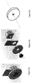
- FIGS. 5 a to 5 c are schematic diagrams of an eccentric mass attached to an actuator
- FIGS. 6 a to 6 c are schematic diagrams of a concentric mass or inertial disc mounted to an actuator
- FIGS. 7 a to 7 c are a model of applied and reaction forces and moments for the eccentric mass of FIG. 5 a;
- FIGS. 8 a and 8 b are a model of the applied and reaction forces and moments for the concentric load (inertial disc) of FIG. 6 a;
- FIGS. 9 a to 9 c are a model for the applied and reaction forces and moments for a pair of pendulum shaped eccentric masses contained within the same plane of rotation and with different oscillation phases, frequencies, or amplitudes about a common rotational axis;
- FIGS. 10 a to 10 c are a model for the applied and reaction forces and moments for a pair of pendulum shaped eccentric masses contained within the same plane of rotation and with the same oscillation phase, frequency, and amplitude in reverse directions about a common rotational axis;
- FIG. 11 a to 11 c are a model for the applied and reaction forces and moments for a pair of pendulum shaped eccentric masses contained in parallel planes of rotation with an offset of d and with arbitrary oscillation phases, frequencies and amplitudes about a common rotational axis;
- FIGS. 12 a to 12 c are a model for the applied and reaction forces and moments for a pair of pendulum shaped eccentric masses contained in parallel planes of rotation with an offset of d and with the same oscillation phase, frequency, and amplitude in reverse directions about a common rotational axis;
- FIGS. 13 a to 13 d are a model for the applied and reaction forces and moments for an inertial disk along with a pair of pendulum shaped eccentric masses contained in parallel planes of rotation with an offset of d and with the same oscillation phase, frequency, and amplitude in reverse directions about a common rotational axis;
- FIGS. 14 a to 14 d are a model for the applied and reaction forces and moments for a rotational disc along with a pair of pendulum shaped eccentric masses contained in parallel planes of rotation with an offset of d and with the same oscillation phase, frequency, and amplitude in reverse directions about a common rotational axis with 180 degrees initial phase offset;
- FIG. 15 is a model of a general multi-axis reaction system
- FIG. 16 is a schematic diagram of forces and moments generated by the general multi-axis reaction system
- FIG. 17 is schematic diagram of a planar cable robot
- FIG. 18 are schematics of a cable robot used for experimentation.
- FIG. 19 is a set of graphs outlining experimental data.
- the disclosure is directed at a method and system for vibration control in a mechanical system.
- a mechanical system include, but are not limited to, a cable robot, a flexible structure, such as a bridge or airplane wings and other similar systems.
- the system of the disclosure may be seen as a multi-axis reaction apparatus or system.
- the multi-axis reaction apparatus includes at least two motors which are co-linear with each other.
- the apparatus further includes a concentric or eccentric inertial load with each of the at least two motors whereby the inertial loads may be rotated by its associated motor to produce a predetermined reaction force and torque which may be applied to the mechanical system in order to control vibration or to counteract any undesired vibrations that are being experienced by the mechanical system.
- FIGS. 5 a to 5 c diagrams of an eccentric mass mounted to an end effector in one embodiment of a system for vibration control is shown.
- FIG. 5 a is a perspective view
- FIG. 5 b is an exploded view
- FIG. 5 c is a schematic model.
- the eccentric mass or eccentric inertial load (seen as pendulum 210 ) is fixed to the shaft of the rotational actuator, where the actuator is fixed to the connector plate.
- the connector plate is attached to the mechanical system.
- the general theory behind the development of the system for vibration control is provided. As will be understood, this theory may then be implemented into an actual system for vibration control such as disclosed with respect to FIG. 2 .
- I o , m, r denote the pendulum's mass moment of inertia, mass, and distance from its mass center to axis of rotation respectively while ⁇ umlaut over ( ⁇ ) ⁇ , ⁇ dot over ( ⁇ ) ⁇ , and ⁇ are the pendulum angular acceleration, angular velocity, and rotational angle, respectively.
- F x F t1 cos( ⁇ 1 ) ⁇ F t2 cos( ⁇ 2 )+ F r2 sin( ⁇ 2 ) ⁇ F r1 sin( ⁇ 1 )
- F y F t1 sin( ⁇ 1 )+ F t2 sin( ⁇ 2 )+ F r2 cos( ⁇ 2 )+ F r1 cos( ⁇ 1 )
- M z M 2 ⁇ M 1 ,respectively.
- FIGS. 11 a to 11 c schematic views of the same system with an offset distance of d between the planes of pendulums are shown.
- F x F t1 cos( ⁇ 1 ) ⁇ F t2 cos( ⁇ 2 )+ F r2 sin( ⁇ 2 ) ⁇ F r1 sin( ⁇ 1 )
- F y F t1 sin( ⁇ 1 )+ F t2 sin( ⁇ 2 )+ F r2 cos( ⁇ 2 )+ F r1 cos( ⁇ 1 ) are the reaction forces and
- M z M 1 - M 2
- ⁇ M y F t ⁇ ⁇ 1 ⁇ d 2 ⁇ cos ⁇ ( ⁇ 1 ) + F t ⁇ ⁇ 2 ⁇ d 2 ⁇ cos ⁇ ( ⁇ 2 ) - F r ⁇ ⁇ 2 ⁇ d 2 ⁇ sin ⁇ ( ⁇ 2 ) + F r ⁇ ⁇ 1 ⁇ d 2 ⁇ sin ⁇ ( ⁇ 1 )
- ⁇ M x - F t ⁇ ⁇ 1 ⁇ d 2 ⁇ sin ⁇ ( ⁇ 1 ) + F t ⁇ ⁇ 2 ⁇ d 2 ⁇ sin ⁇ ( ⁇ 2 ) + F r ⁇ ⁇ 2 ⁇ d 2 ⁇ cos ⁇ ( ⁇ 2 ) - F r ⁇ ⁇ 1 ⁇ d 2 ⁇ cos ⁇ ( ⁇ 1 ) are the reaction moments which are calculated in the midpoint of connection line, as shown in FIG. 12 c
- FIG. 12 a a schematic view of the same system with an offset distance of d between the planes of the pendulums is shown.
- the eccentric masses may be an oscillatory reaction disc as schematically shown in FIGS. 6 a to 6 c .
- Use of a reaction disc allows a pure oscillatory moment to be generated to cancel, or counteract, the unnecessary moments of the multi-axis reaction system or to add a moment in a desired direction.
- the oscillatory disc can provide only an axial reaction moment.
- the oscillatory reaction disc may be used as the only inertial load or may be combined with the pendulum-shaped eccentric masses as discussed above.
- FIG. 13 a the schematic embodiment of the multi-axis reaction system of FIGS. 12 a to 12 c are shown wherein the set of masses include a reaction disc is preferably mounted at a center point between the connection points of the pendulum eccentric masses and the disc's axis of rotation is perpendicular to the pendulums rotational axes.
- the system can generate a pure oscillatory force by using the reaction disc to cancel the resultant moment of the pendulum loads or to provide a desired moment in that direction.
- FIG. 14 a a schematic view of a second embodiment of an eccentric mass starting orientation is shown.
- the starting positions, or orientations, of the eccentric masses have an impact on the generated forces/moments.
- the necessary forces may be generated by the system of the disclosure to counteract the undesired vibrations of the mechanical system.
- the undesired vibrations may be measured or sensed by sensors located on or around the mechanical system.
- FIGS. 15 and 16 schematically show a general embodiment of a system for vibration control and a resultant force map, respectively.
- a combination of two reaction pendulums and a disc as shown in Figure FIGS. 13 a to 13 d can generate a pure force while a reaction disc can generate a pure moment, hence, a general multi-axis reaction system with six pendulum-shaped eccentric masses and three discs, as shown in FIG. 15 , can generate all three forces and three moments necessary for controlling any rotational and translational undesired vibrations in mechanical systems.
- FIG. 16 shows the force map for the three forces and three moments of a general multi-axis reaction system.
- FIG. 1 a perspective view of an embodiment of a mechanical system which may benefit from the system for vibration control is shown.
- the mechanical system is a cable robot.
- the warehousing cable robot 100 includes a platform 102 from which a set of cables 104 extend. At one end, or a first end, of each cable 104 , the cable 104 is connected to the platform 102 and at the opposite, or second end, the cable 104 is connected to a motor or a winch (not shown) that is actuated by a motor for controlling a length or tension in the cable 104 .
- the warehousing robot 100 may further include a cable controlling apparatus or mechanism for receiving and/or collecting the cable that is controlled by the, preferably, rotary motor.
- the apparatus 100 may further include a frame 110 which supports the platform 102 and the cables 104 .
- the cable controlling mechanism and the motor may be mounted within or to the frame 110 .
- Control of the cable robot is via a central processing unit (CPU) 111 .
- CPU central processing unit
- the warehousing robot 100 may include other components necessary for operation or for other functionality, however, these are not shown as the disclosure is directed at the apparatus for controlling undesired vibrations of the platform to reduce or prevent unwanted motion of the platform when the warehousing robot is in use.
- a user can control the cable robot 100 to obtain items from the slots 112 of a shelving unit 114 located within a warehouse.
- the cable robot 100 may further include a robot arm or the like, which may be mounted or connected to the platform 102 , to reach into the slots 112 to retrieve the requested item.
- the platform 102 is controlled to deliver the item to the user or to a specified location. The delivery of the item will be understood by one skilled in the art.
- a signal is transmitted via the CPU 111 to the cable robot 100 identifying the location of the requested item.
- the CPU may transmit signals to the motor and cable controlling mechanism to move the platform.
- the platform 102 is then moved to the item location whereby the item is then retrieved and placed on the platform 102 .
- the warehousing robot 100 is associated with a wall or shelf of objects and therefore, once the warehousing robot 102 receives the signal, the platform is controlled to move parallel to the shelf to locate the object in the XY plane and then controlled to move perpendicular to the wall (in the Z-plane) to retrieve the object.
- the vibration of the platform can be controlled however, depending on the configuration and design of cable robot, controllability conditions of the moving platform in some directions may not be possible. In such cable robots, the vibrations of the platform in all directions cannot be controlled simply by controlling the tension of the cables. Accordingly, a multi-axis reaction system (as schematically disclosed above) attached to the platform can be used to provide the required forces/moments to effectively reduce or eliminate undesired vibrations of the platform.
- any desired forces in x, y directions denoted F x and F y as well as any desired moment in the z-direction, denoted by M z , can be provided by the cables.
- F x , F y and M z the platform's planar vibrations (in x, y and ⁇ z directions) can be controlled.
- FIG. 2 a schematic diagram of one embodiment of a multi-axis reaction system for vibration control of the cable robot is shown.
- the system of FIG. 2 is used to control undesired vibrations in the translation about the planar normal axis and rotation about the two planar axes.
- adding the multi-axis reaction system can provide a number of actuation inputs (forces and/or moments) to provide controllability conditions for the control of the platform.
- An explanation of controllability conditions and the conditions of the planar cable robots with and without the multi-axis reaction system are discussed below.
- the system 200 is shown mounted to the bottom of a platform 102 of the warehousing robot 100 with cables 104 extending from the platform 102 .
- the system 200 is preferably mounted to the platform 102 .
- the system 200 includes a pair of connector plates, or walls, 202 which are fixed to the platform via fasteners, such as bolts and nuts and a set of at least two motors 204 which are mounted to the walls 202 .
- the set of motors includes two motors that are located adjacent each other and share a single axis of rotation 206 . In this manner, the motors 204 may be seen as being co-linear with respect to each other.
- the axis of rotation is parallel to the platform 102 .
- the system 200 further includes a set of loads, seen as eccentric masses 210 , preferably in a one-to-one relationship with each of the set of motors 204 .
- the individual loads may be seen as being asymmetric eccentric masses.
- Each eccentric mass 210 is mounted to, or engaged with, the end effector 208 of its associated motor 204 about the axis of rotation 206 .
- An example of an eccentric mass is shown in FIG. 3 .
- the actual centre of gravity of each load 210 does not correspond with the axis of rotation 206 but is displaced a predetermined distance from the axis 206 .
- the predetermined distance and the weight of the pendulum is preferably stored in the memory of CPU 111 .
- an applied torque along the motor shaft (about the axis of rotation) generates a set of forces and moments such as disclosed above with respect to the force maps.
- the reaction force from the load also generates a secondary set of reaction moments, due the displacement of the force from the various rotational axes.
- the eccentric mass 210 is preferably pendulum shaped with a hole 212 at one end (to receive the end effector 208 ) and a pendulum portion 214 at an opposite end.
- the hole 212 mates with, or is attached to a shaft of the end effector 208 and is then mounted to, or attached to the end effector 208 in any number of known methods such that rotation of the end effector 208 causes the pendulum portion 214 of the load 210 to move or rotate.
- actuation of the motor preferably causes the pendulum portion 214 of the load 210 to rotate at a predetermined angle and/or speed about the axis of rotation 206 .
- Movement of each eccentric mass generates a force and/or torque that may be then applied to or experienced by the platform 102 .
- the force or forces and/or the torque or torques that are generated by the vibration control system 200 may be used to counteract or control the undesired vibrations being experienced by the platform 102 .
- FIG. 4 a flowchart outlining a method of vibration control is shown.
- measurements/estimations associated with undesired vibrations being experienced by the platform (or mechanical system) are obtained 500 .
- the position of the moving platform and/or its undesired vibrations can be measured directly via sensors such as cameras and accelerometers, or estimated using different estimation methods. These techniques will be understood by one skilled in the art.
- these undesired vibrations represent the vibrations which are not currently controlled by the cables.
- the required torques/forces to control the undesired vibrations are then calculated 502 . This may be performed by a controller of the system of the disclosure or by a processor. A mapping is then performed to convert the torques/forces into speed and phase values 504 for movement of the loads (which for a cable robot is preferably two pendulum loads). Controllers associated with the motors then actuate 506 the motors to generate the necessary speed and phase to move the pendulums whereby the torque/forces are then applied to the platform to counteract the undesired vibrations 508 . This is then continuously repeated to assist in controlling and counteracting the undesired vibrations being experienced by the mechanical system (or platform in the case of a cable robot).
- m p is the mass of the platform
- g is the gravitational acceleration vector
- w is the vector of angular velocities
- F c and M c are the force and moment vectors provided by the cables which are a function of p, q and u.
- R r [ cos ⁇ ⁇ ( ⁇ ) ⁇ cos ⁇ ( ⁇ ) sin ⁇ ( ⁇ ) 0 - cos ⁇ ( ⁇ ) ⁇ cos ⁇ ( ⁇ ) cos ⁇ ( ⁇ ) 0 sin ⁇ ( ⁇ ) 0 1 ]
- X . [ p . M p - 1 ⁇ ( F c + m p ⁇ g ) q . R r - 1 ⁇ [ I p - 1 ⁇ ( M c - ( R r ⁇ q . ) ⁇ ( I b ⁇ R r ⁇ q . ) ) - R . r ⁇ q . ] ]
- the resulting non-linear state space model can be linearized using Taylor series expansion about an equilibrium point. Any location within the plane of the platform can be used as a potential equilibrium point so long as the elements of u are chosen such that the cable tensions hold the platform in a state of static equilibrium.
- a and B are two matrices that depend on the cable properties, their attachment points, and moving platform inertia properties.
- controllability matrix Q [ B AB A 2 B . . . A 11 B ]
- FIG. 2 In order to address the controllability problem, the system of FIG. 2 may be implemented.
- the Lagrangian method can be used. This can be done by calculating the Lagrangian (L) which can be formed as:
- T p and V p are the total kinetic and potential energy of the whole system.
- V c,i is the potential energy of ith cable
- T p and V p denote the kinetic and potential energy of the platform
- T a,i and V a,i denote those of ith pendulum.
- V c,i 1 ⁇ 2 k i ( l i ⁇ l i ) 2
- the motion of the pendulum center of mass depends on the actuator's rotational motion and the platform motion.
- R b g , r a,i , and l a,i denote the rotational matrix to transform the vectors from the platform coordinate system to the ground coordinate system, the pendulum center of mass position vector with respect to its axis, and the vector of pendulum connection point with respect to the platform center of mass.
- V a,i m a,i ( g ⁇ p a,i )
- ⁇ a,1 and ⁇ a,2 are the applied torques for the two pendulums.
- X [ p p . q q . ⁇ a , 1 ⁇ . a , 1 ⁇ a , 2 ⁇ . a , 2 ]
- u [ ⁇ ⁇ ⁇ l 1 ⁇ ⁇ ⁇ l 2 ⁇ ⁇ ⁇ l 3 ⁇ ⁇ ⁇ l 4 ⁇ a , 1 ⁇ a , 2 ]
- ⁇ a,1 and ⁇ a,2 are the angles of the pendulums and ⁇ a,1 and ⁇ a,s denote corresponding actuators' torque.
- the size of matrices A and B are 16 ⁇ 16 and 16 ⁇ 6, respectively.
- a 1 : 16 ⁇ 1 : 9 [ 0 0 0 1.0 0 0 0 0 0 0 0 0 0 0 0 0 1.0 0 0 0 0 0 0 - 102.0 0 0 0 0 0 0 0 0 0 5.11 0 - 69.5 0 0 0 0 0 0 0 0 0 - 70.0 0 0 0 - 0.982 0 0 0 0 0 0 0 0 0 0 0 0 0 0 0 0 0 0 0 0 0 0 0 0 0 0 0 0 0 0 0 0 0 0 0 0 0 0 0 0 0 0 0 0 0 0 0 0 0 0 0 0 0 0 0 0 0 0 0 0 0 0 0 0 0 0
- Constructing the controllability matrix Q for the new linearized system reveals that its rank is 16 (full-rank) for any point of the robot workspace. Having the controllability condition satisfied, different control technique can be used for using the multi-axis reaction system for eliminating the moving platform vibration.
- FIG. 19 graphs reflecting the vibration of the moving platform in the out-of-the-plane (Z direction) and rotational vibration about X axis with and without the multi-axis reaction system are shown.
- a sliding mode control was used to damp out the platform vibration in the two directions. As can be seen, these two vibration directions are not controllable without the multi-axis reaction system.
- Other control methods could also be adapted and used for the application of multi-axis reaction system in this warehousing robot.
- the sliding mode control is just an example to show the effect of the multi-axis reaction system in vibration control of mechanical systems.
- the movement of the motors is controlled by a processor or a controller.
- the controller receives instructions from the processor to actuate the motors in accordance to eccentric masses movement instructions values.
- the controller for controlling the system for vibration control may be the same or may be different from the controller for controlling the mechanical system.
Landscapes
- Engineering & Computer Science (AREA)
- Mechanical Engineering (AREA)
- General Engineering & Computer Science (AREA)
- Robotics (AREA)
- Physics & Mathematics (AREA)
- Acoustics & Sound (AREA)
- Aviation & Aerospace Engineering (AREA)
- Human Computer Interaction (AREA)
- Manufacturing & Machinery (AREA)
- General Physics & Mathematics (AREA)
- Automation & Control Theory (AREA)
- Manipulator (AREA)
Abstract
Description
F x =F t1 cos(θ1)−F t2 cos(θ2)+F r2 sin(θ2)−F r1 sin(θ1),F y =F t1 sin(θ1)+F t2 sin(θ2)+F r2 cos(θ2)+F r1 cos(θ1),M z =M 2 −M 1,respectively.
F x =F t1 cos(θ1)−F t2 cos(θ2)+F r2 sin(θ2)−F r1 sin(θ1),F y =F t1 sin(θ1)+F t2 sin(θ2)+F r2 cos(θ2)+F r1 cos(θ1)
are the reaction forces and
are the reaction moments which are calculated in the midpoint of connection line, as shown in
| TABLE 1 | ||
| Cable | rc, i [m] | bi [m] |
| Index | x | y | z | x | | z | |
| 1 | 0.152 | 0.048 | 0.065 | 1.50 | 0.500 | 0.000 |
| 2 | 0.232 | −0.048 | 0.000 | 1.58 | 0.404 | 0.065 |
| 3 | 0.222 | −0.017 | 0.087 | 1.50 | −0.500 | 0.000 |
| 4 | −0.222 | −0.017 | 0.087 | −1.50 | −0.500 | 0.000 |
| 5 | −0.232 | −0.048 | 0.000 | −1.58 | 0.404 | 0.065 |
| 6 | −0.152 | 0.048 | 0.065 | −1.50 | 0.500 | 0.000 |
| 7 | 0.152 | 0.048 | −0.065 | 1.50 | 0.500 | 0.000 |
| 8 | 0.232 | −0.048 | 0.000 | 1.58 | 0.404 | −0.065 |
| 9 | 0.222 | −0.017 | −0.087 | 1.50 | −0.500 | 0.000 |
| 10 | −0.222 | −0.017 | −0.087 | −1.50 | −0.500 | 0.000 |
| 11 | −0.232 | −0.048 | 0.000 | −1.58 | 0.404 | −0.065 |
| 12 | −0.152 | 0.048 | −0.065 | −1.50 | 0.500 | 0.000 |
M p {umlaut over (p)}=F c +m p g
I p {dot over (ω)}=M c−ω×(I pω)
where mp is the mass of the platform, g is the gravitational acceleration vector, Mp=mp I3×3 and Ip are the mass and inertia matrices associated with the mobile box, w is the vector of angular velocities, and Fc and Mc are the force and moment vectors provided by the cables which are a function of p, q and u.
{umlaut over (p)}=M p −1(F c +m p g)
{umlaut over (q)}=R r −1[I p −1(M c−(R r {dot over (q)})×(I b R r {dot over (q)}))−{dot over (R)} r {dot over (q)}]
{dot over (X)}=A 12×12 X+B 12×4 u
Q=[B AB A 2 B . . . A 11 B]
T p=½m p({dot over (p)}·{dot over (p)})+½ωT I pω
V p =m p {right arrow over (g)}(p·ĵ)
V c,i=½k i(l i −δl i)2
p a,i =p+R b g(r a,i +l a,i)
{dot over (p)} a,i ={dot over (p)}+R b g[(ωp ×r a,i)+(ωa,i ×l a,i)]
ωa,i=ω+{dot over (θ)}a,i
T a,i=½m a,i({dot over (p)} a,i ·{dot over (p)} a,i)+½ωa,i T I a,iωa,i
V a,i =m a,i(g·p a,i)
{dot over (X)}=A 16×16 X+B 16×6 u
| Para- | |||
| meter | Value | ||
| ma,i | 0.6 kg | ||
| Ia,i |
|
||
| ra,i | [0.2325, −0.0480, 0]T m | ||
| ra,i | [−0.2325, −0.0480, 0]T m | ||
| la,i | [0, −0.05, 0]T m | ||
Claims (15)
Priority Applications (3)
| Application Number | Priority Date | Filing Date | Title |
|---|---|---|---|
| US15/433,325 US10914357B2 (en) | 2017-02-15 | 2017-02-15 | Multi-axis reaction system and method for vibration control of mechanical systems |
| PCT/CA2018/050156 WO2018148825A1 (en) | 2017-02-15 | 2018-02-12 | Multi-axis reaction system and method for vibration control of mechanical systems |
| CA3053666A CA3053666A1 (en) | 2017-02-15 | 2018-02-12 | Multi-axis reaction system and method for vibration control of mechanical systems |
Applications Claiming Priority (1)
| Application Number | Priority Date | Filing Date | Title |
|---|---|---|---|
| US15/433,325 US10914357B2 (en) | 2017-02-15 | 2017-02-15 | Multi-axis reaction system and method for vibration control of mechanical systems |
Publications (2)
| Publication Number | Publication Date |
|---|---|
| US20180231100A1 US20180231100A1 (en) | 2018-08-16 |
| US10914357B2 true US10914357B2 (en) | 2021-02-09 |
Family
ID=63105812
Family Applications (1)
| Application Number | Title | Priority Date | Filing Date |
|---|---|---|---|
| US15/433,325 Active 2038-12-09 US10914357B2 (en) | 2017-02-15 | 2017-02-15 | Multi-axis reaction system and method for vibration control of mechanical systems |
Country Status (3)
| Country | Link |
|---|---|
| US (1) | US10914357B2 (en) |
| CA (1) | CA3053666A1 (en) |
| WO (1) | WO2018148825A1 (en) |
Families Citing this family (10)
| Publication number | Priority date | Publication date | Assignee | Title |
|---|---|---|---|---|
| WO2019123318A1 (en) * | 2017-12-22 | 2019-06-27 | Marchesini Group S.P.A. | A cable-driven robot |
| DE102019101623A1 (en) * | 2019-01-23 | 2020-07-23 | Liebherr-Werk Biberach Gmbh | Rope robot |
| CN109610673B (en) * | 2019-02-01 | 2023-11-24 | 青岛理工大学 | Active inertia drive control system |
| WO2020206532A1 (en) * | 2019-04-08 | 2020-10-15 | 10087530 Canada Inc. D/B/A Rbot9 Automation | Cable robot |
| JP7226070B2 (en) * | 2019-04-26 | 2023-02-21 | ブラザー工業株式会社 | Numerical controller |
| US11597077B2 (en) * | 2020-07-22 | 2023-03-07 | Saudi Arabian Oil Company | Cable suspended robot for industrial plants |
| EP4248186A1 (en) * | 2020-11-19 | 2023-09-27 | Alpinestars Research S.p.A. | Method for testing electronic control units of airbag protection devices and testing machine designed to implement said method |
| AT525685B1 (en) * | 2021-12-06 | 2023-12-15 | Hans Kuenz Gmbh | Method for regulating a movement of a load in a working space of a load transport device |
| US12233545B2 (en) | 2022-03-30 | 2025-02-25 | Saudi Arabian Oil Company | Modular, propelled cable suspended robot for industrial plants and unmanned offshore platforms |
| CN116553055B (en) * | 2023-06-27 | 2024-01-26 | 南京线控机器人科技有限公司 | Intelligent logistics warehouse system and deployment method |
Citations (6)
| Publication number | Priority date | Publication date | Assignee | Title |
|---|---|---|---|---|
| US4741303A (en) | 1986-10-14 | 1988-05-03 | Tecumseh Products Company | Combination counterbalance and oil slinger for horizontal shaft engines |
| US20100034655A1 (en) | 2004-08-30 | 2010-02-11 | Jolly Mark R | Helicopter hub mounted vibration control and circular force generation systems for canceling vibrations |
| US20100107807A1 (en) * | 2006-12-15 | 2010-05-06 | Soletanche Freyssinet | Device for vibration control of a structure |
| US20120227485A1 (en) * | 2009-09-19 | 2012-09-13 | Bruce Gregory | Balanced and Eccentric Mass Compact Pendulum with Dynamic Tuning |
| DE202012001439U1 (en) * | 2012-01-10 | 2013-04-11 | Viktor Arestov | torque converter |
| GB2538591A (en) | 2016-02-18 | 2016-11-23 | Ford Global Tech Llc | A balance assembly |
-
2017
- 2017-02-15 US US15/433,325 patent/US10914357B2/en active Active
-
2018
- 2018-02-12 CA CA3053666A patent/CA3053666A1/en active Pending
- 2018-02-12 WO PCT/CA2018/050156 patent/WO2018148825A1/en not_active Ceased
Patent Citations (7)
| Publication number | Priority date | Publication date | Assignee | Title |
|---|---|---|---|---|
| US4741303A (en) | 1986-10-14 | 1988-05-03 | Tecumseh Products Company | Combination counterbalance and oil slinger for horizontal shaft engines |
| US20100034655A1 (en) | 2004-08-30 | 2010-02-11 | Jolly Mark R | Helicopter hub mounted vibration control and circular force generation systems for canceling vibrations |
| US20100107807A1 (en) * | 2006-12-15 | 2010-05-06 | Soletanche Freyssinet | Device for vibration control of a structure |
| US20120227485A1 (en) * | 2009-09-19 | 2012-09-13 | Bruce Gregory | Balanced and Eccentric Mass Compact Pendulum with Dynamic Tuning |
| DE202012001439U1 (en) * | 2012-01-10 | 2013-04-11 | Viktor Arestov | torque converter |
| GB2538591A (en) | 2016-02-18 | 2016-11-23 | Ford Global Tech Llc | A balance assembly |
| GB2538591B (en) * | 2016-02-18 | 2019-02-20 | Ford Global Tech Llc | An engine balance assembly using electric motors |
Non-Patent Citations (2)
| Title |
|---|
| Canadian Intellectual Property Office as International Searching Authority, International Preliminary Report on Patentability for PCT/CA2018/050156, dated Aug. 20, 2019. |
| Canadian Intellectual Property Office as International Searching Authority, International Search Report for PCT/CA2018/050156, dated Apr. 30, 2018. |
Also Published As
| Publication number | Publication date |
|---|---|
| US20180231100A1 (en) | 2018-08-16 |
| CA3053666A1 (en) | 2018-08-23 |
| WO2018148825A1 (en) | 2018-08-23 |
Similar Documents
| Publication | Publication Date | Title |
|---|---|---|
| US10914357B2 (en) | Multi-axis reaction system and method for vibration control of mechanical systems | |
| McInroy et al. | Design and control of flexure jointed hexapods | |
| Uyama et al. | Impedance-based contact control of a free-flying space robot with a compliant wrist for non-cooperative satellite capture | |
| de Rijk et al. | Out-of-plane vibration control of a planar cable-driven parallel robot | |
| Malgaca et al. | Residual vibration control of a single-link flexible curved manipulator | |
| Rushton et al. | Multiaxis reaction system (MARS) for vibration control of planar cable-driven parallel robots | |
| Jamshidifar et al. | A reaction-based stabilizer for nonmodel-based vibration control of cable-driven parallel robots | |
| George et al. | Inertial vibration damping control of a flexible base manipulator | |
| Ahmad et al. | Dynamic modelling of a two-link flexible manipulator system incorporating payload | |
| Yoshida et al. | Impact dynamics of space long reach manipulators | |
| Yoshida et al. | Experimental research on impact dynamics of spaceborne manipulator systems | |
| Yoshida et al. | Impact dynamics of space manipulators mounted on a flexible structure | |
| Mavroidis et al. | Inferred end-point control of long reach manipulators | |
| Jnifene et al. | A computed torque/time delay approach to the end-point control of a one-link flexible manipulator | |
| Nagaoka et al. | Bimodal mobility actuated by inertial forces with surface elastic bodies in microgravity | |
| Nohmi et al. | Microgravity experiment for attitude control of a tethered body by arm link motion | |
| Nohmi | Experimental analysis for attitude control of a tethered space robot under microgravity | |
| Dixit et al. | Cable stiffened flexible link manipulator | |
| Šika et al. | Active multidimensional vibration absorbers for light robots | |
| Kim et al. | Multi-axis vibration control of a slender structure by using Stewart platform manipulator | |
| CHALERMPONG et al. | Vibration reduction of the rotary crane with flexible boom | |
| Chen et al. | Impact dynamic modeling of space flexible manipulators based on continuous approach | |
| Ankaralı et al. | Response spectrum of a coupled flexible shaft-flexible beam system for cycloidal input motion | |
| Yoshida et al. | Dynamics and Control of a Space Robot Capturing a Floating Target: Impact Estimation Experiments | |
| Marghitu et al. | Control of a parametrically excited flexible beam undergoing rotation and impacts |
Legal Events
| Date | Code | Title | Description |
|---|---|---|---|
| AS | Assignment |
Owner name: KHAJEPOUR, AMIR, CANADA Free format text: ASSIGNMENT OF ASSIGNORS INTEREST;ASSIGNORS:RUSHTON, MITCHELL MACLEOD;JAMSHIDIFAR, HAMED;REEL/FRAME:041263/0695 Effective date: 20161205 |
|
| STPP | Information on status: patent application and granting procedure in general |
Free format text: DOCKETED NEW CASE - READY FOR EXAMINATION |
|
| STPP | Information on status: patent application and granting procedure in general |
Free format text: NON FINAL ACTION MAILED |
|
| STPP | Information on status: patent application and granting procedure in general |
Free format text: RESPONSE TO NON-FINAL OFFICE ACTION ENTERED AND FORWARDED TO EXAMINER |
|
| STPP | Information on status: patent application and granting procedure in general |
Free format text: FINAL REJECTION MAILED |
|
| STPP | Information on status: patent application and granting procedure in general |
Free format text: NOTICE OF ALLOWANCE MAILED -- APPLICATION RECEIVED IN OFFICE OF PUBLICATIONS |
|
| STPP | Information on status: patent application and granting procedure in general |
Free format text: PUBLICATIONS -- ISSUE FEE PAYMENT RECEIVED |
|
| STCF | Information on status: patent grant |
Free format text: PATENTED CASE |
|
| MAFP | Maintenance fee payment |
Free format text: PAYMENT OF MAINTENANCE FEE, 4TH YR, SMALL ENTITY (ORIGINAL EVENT CODE: M2551); ENTITY STATUS OF PATENT OWNER: SMALL ENTITY Year of fee payment: 4 |