US10911780B2 - Multi-viewpoint image coding apparatus, multi-viewpoint image coding method, and storage medium - Google Patents
Multi-viewpoint image coding apparatus, multi-viewpoint image coding method, and storage medium Download PDFInfo
- Publication number
- US10911780B2 US10911780B2 US15/264,074 US201615264074A US10911780B2 US 10911780 B2 US10911780 B2 US 10911780B2 US 201615264074 A US201615264074 A US 201615264074A US 10911780 B2 US10911780 B2 US 10911780B2
- Authority
- US
- United States
- Prior art keywords
- unit
- camera
- coding
- image data
- distance
- Prior art date
- Legal status (The legal status is an assumption and is not a legal conclusion. Google has not performed a legal analysis and makes no representation as to the accuracy of the status listed.)
- Active, expires
Links
- 238000000034 method Methods 0.000 title claims abstract description 75
- 230000006870 function Effects 0.000 claims description 8
- 230000007423 decrease Effects 0.000 claims description 4
- 230000008569 process Effects 0.000 abstract description 50
- 238000010586 diagram Methods 0.000 description 26
- 238000003384 imaging method Methods 0.000 description 26
- 238000005516 engineering process Methods 0.000 description 10
- 230000006835 compression Effects 0.000 description 6
- 238000007906 compression Methods 0.000 description 6
- 230000007704 transition Effects 0.000 description 6
- 230000002093 peripheral effect Effects 0.000 description 5
- 230000003287 optical effect Effects 0.000 description 4
- 230000008859 change Effects 0.000 description 3
- 238000004891 communication Methods 0.000 description 3
- 238000009432 framing Methods 0.000 description 3
- 239000002131 composite material Substances 0.000 description 2
- 239000000470 constituent Substances 0.000 description 2
- 230000003247 decreasing effect Effects 0.000 description 2
- 238000003825 pressing Methods 0.000 description 2
- 238000013139 quantization Methods 0.000 description 2
- 230000008901 benefit Effects 0.000 description 1
- 230000005540 biological transmission Effects 0.000 description 1
- 238000012986 modification Methods 0.000 description 1
- 230000004048 modification Effects 0.000 description 1
- 239000004065 semiconductor Substances 0.000 description 1
Images


Classifications
-
- H—ELECTRICITY
- H04—ELECTRIC COMMUNICATION TECHNIQUE
- H04N—PICTORIAL COMMUNICATION, e.g. TELEVISION
- H04N19/00—Methods or arrangements for coding, decoding, compressing or decompressing digital video signals
- H04N19/50—Methods or arrangements for coding, decoding, compressing or decompressing digital video signals using predictive coding
- H04N19/597—Methods or arrangements for coding, decoding, compressing or decompressing digital video signals using predictive coding specially adapted for multi-view video sequence encoding
-
- H—ELECTRICITY
- H04—ELECTRIC COMMUNICATION TECHNIQUE
- H04N—PICTORIAL COMMUNICATION, e.g. TELEVISION
- H04N13/00—Stereoscopic video systems; Multi-view video systems; Details thereof
- H04N13/20—Image signal generators
- H04N13/204—Image signal generators using stereoscopic image cameras
- H04N13/239—Image signal generators using stereoscopic image cameras using two 2D image sensors having a relative position equal to or related to the interocular distance
-
- H—ELECTRICITY
- H04—ELECTRIC COMMUNICATION TECHNIQUE
- H04N—PICTORIAL COMMUNICATION, e.g. TELEVISION
- H04N13/00—Stereoscopic video systems; Multi-view video systems; Details thereof
- H04N13/20—Image signal generators
- H04N13/204—Image signal generators using stereoscopic image cameras
- H04N13/243—Image signal generators using stereoscopic image cameras using three or more 2D image sensors
-
- H—ELECTRICITY
- H04—ELECTRIC COMMUNICATION TECHNIQUE
- H04N—PICTORIAL COMMUNICATION, e.g. TELEVISION
- H04N13/00—Stereoscopic video systems; Multi-view video systems; Details thereof
- H04N13/10—Processing, recording or transmission of stereoscopic or multi-view image signals
- H04N13/106—Processing image signals
- H04N13/161—Encoding, multiplexing or demultiplexing different image signal components
-
- H—ELECTRICITY
- H04—ELECTRIC COMMUNICATION TECHNIQUE
- H04N—PICTORIAL COMMUNICATION, e.g. TELEVISION
- H04N13/00—Stereoscopic video systems; Multi-view video systems; Details thereof
- H04N2013/0074—Stereoscopic image analysis
- H04N2013/0081—Depth or disparity estimation from stereoscopic image signals
Definitions
- the present invention relates to a multi-viewpoint image coding apparatus coding a multi-viewpoint image, a multi-viewpoint image coding method, and a storage medium.
- a technology for compressing and coding image information a technology for coding in compliance with a moving picture experts group (MPEG) standard is known, and, generally, MPEG2, MPEG4, MPEG4AVC, and the like are widely used.
- MPEG moving picture experts group
- a main feature of such compressing and coding technologies is to code a difference between a picture of a predictive coding target (hereinafter, referred to as a predictive coding target picture) and a picture that has already been coded and reconfigured (hereinafter, referred to as a reference picture). More specifically, a discrete cosine transform (DCT) and quantization are performed for a difference between a predictive coding target picture and a reference picture, and variable-length coding is performed for a result of the quantization.
- DCT discrete cosine transform
- image data coded according to the MPEG2 is configured by three types of pictures including an I picture, a P picture, and a B picture.
- An I picture is a picture that is coded without reference to any other picture.
- the I picture can be decoded as a single object.
- a P picture is coded, an I picture or a P picture of the past is referred to.
- the P picture is coded using a difference from a picture that has been referred to.
- an I picture or a P picture of the past is referred to. For this reason, it is necessary to decode the I picture or the P picture to be referred to in advance.
- a multi-viewpoint video coding technology for coding moving image data captured from a plurality of viewpoints (moving image data of a plurality of channels) in compliance with an H.264/MVC standard has been known.
- a plurality of pieces of moving image data is data acquired by imaging a subject from a plurality of viewpoints and thus have a feature that the moving image data is similar.
- the compression rate is improved using this feature (correlation).
- moving image data of one channel is coded by referring to moving image data of the other channels.
- the H.264/MVC standard for example, is used when a three-dimensional image that can be felt to be stereoscopic by a viewer is coded.
- Japanese Patent Laid-Open No. 2007-184741 a technique for coding a video sequence acquired from a plurality of video cameras has been proposed.
- a video sequence of a video camera (base video camera) arranged at a center position of all the video cameras is independently coded, and a video sequence of an adjacent video camera is coded by referring to the video sequence that has been coded in advance. Thereafter, a similar process is repeated for a video sequence of a video camera that is adjacent to the video camera of which the video sequence has been coded, and image data of video cameras disposed on the periphery of the base video camera is sequentially coded.
- an object of the present invention is to provide a multi-viewpoint coding apparatus increasing the processing speed in a process of coding a multi-viewpoint images while suppressing the amount of data, a multi-viewpoint image coding method, and a storage medium.
- a multi-viewpoint image coding apparatus coding image data, which has a different viewpoint, acquired from each of a plurality of camera units.
- the multi-viewpoint image coding apparatus includes: a distance estimating unit that estimates a distance from a camera array including the plurality of camera units up to a subject; a determination unit that determines the number of first camera units independently coding image data among the plurality of camera units and an arrangement of the first camera units in the camera array based on the distance estimated by the distance estimating unit; and a control unit that operates each of the camera units as the first camera unit or as a second camera unit coding image data of the own camera unit by referring to image data of the first camera unit based on the number and the arrangement of the first camera units determined by the determination unit.
- FIGS. 1A and 1B are explanatory diagrams that illustrate an overview of an imaging apparatus of a multi-eye type according to a first embodiment
- FIG. 2 is an explanatory diagram that illustrates an example of the configuration of an imaging apparatus of a multi-eye type according to the first embodiment
- FIG. 3 is an explanatory diagram that illustrates the internal configuration of a coding circuit and a coding circuit control unit
- FIGS. 4A to 4D are explanatory diagrams that illustrate examples of the arrangement of camera units
- FIG. 5 is a state transition diagram that illustrates state transitions of an imaging apparatus of a multi-eye type
- FIGS. 6A and 6B are explanatory diagrams that illustrate a correlation between a distance from a camera array to a subject and a reference camera unit;
- FIGS. 7A and 7B are diagrams that illustrate a reference camera unit determining method in a case where the number of the reference camera unit is determined to be one;
- FIG. 8 is an explanatory diagram that illustrates an appearance in which camera units having mutually-different viewing angles are alternately arranged
- FIG. 9 is a flowchart that illustrates a coding process performed by the coding circuit control unit
- FIG. 10 is a diagram that illustrates a predictive coding process of moving image data captured at a plurality of viewpoints
- FIG. 11 is a flowchart that illustrates a distance estimating process performed by a distance estimating unit
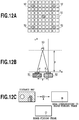
- FIGS. 12A to 12C are diagrams that illustrate a distance estimating process
- FIG. 13 is a diagram that illustrates a predictive coding process using difference processing.
- FIG. 14 is an explanatory diagram that illustrates a range of a referring camera unit corresponding to a reference camera unit.
- FIGS. 1A and 1B are explanatory diagrams that illustrate an overview of an imaging apparatus (hereinafter, referred to as a multi-eye camera) 100 of a multi-eye type according to a first embodiment.
- FIG. 1A illustrates an overview diagram acquired by seeing the multi-eye camera 100 from the front side.
- FIG. 1B illustrates an overview diagram acquired by seeing the multi-eye camera 100 from the back side.
- a camera array in which a plurality of camera units 101 are arranged is arranged on a front face (a face disposed on the front side in FIG. 1A ) of the multi-eye camera 100 , and a release button 106 directing start of photographing is arranged on an upper face (a face disposed on an upper side in FIG. 1A ).
- Each camera unit 101 includes: an imaging lens 102 ; an optical filter 103 ; an imaging device 104 ; and a peripheral circuit 105 .
- images of a plurality of viewpoints are acquired by performing simultaneous photographing using the camera array.
- a memory card slot 113 for mounting a recording medium such as a semiconductor memory card is arranged on a side face (a face disposed on the right side in FIG. 1B ) of the multi-eye camera 100 .
- a serial bus interface such as a USB may be arranged such that a storage device such as a hard disk drive is connected through a serial bus.
- a rear face a face disposed on the front side in FIG.
- a display unit 107 of the multi-eye camera 100 , a display unit 107 , a key group 108 arranged in a cross shape, a power button 109 , a menu button 110 , a determination button 111 , a cancel button 112 , and the like are arranged.
- the multi-eye camera 100 does not include an optical finder, and thus, a user performs a framing operation (focusing or layout checking) using an image displayed on the display unit 107 .
- a live view displaying a capture range in real time
- a camera setting menu displayed when the menu button 110 is pressed, and the like are displayed.
- the live view is displayed again on the display unit 107 .
- the user changes the state of a selected setting item by operating the key group 108 and determines the change by pressing the determination button 111 or cancels the change by pressing the cancel button 112 .
- setting items that can be changed on the camera setting menu there are switching among capture modes such as a moving image capture mode and a still image capture mode, a diaphragm value, a shutter speed, and the like.
- a diaphragm value, a shutter speed, and a zoom position will be described to be set to same values for the camera units 101 configuring the camera array, different values may be set to each camera unit 101 .
- a photographing distance (focusing) for example, a CPU 200 to be described later calculates a distance up to a subject corresponding to an automatic focus (AF) range-finding frame designated by an operation for a touch screen or the key group 108 of the display unit 107 and sets the calculated distance as a photographing distance for all the camera units.
- AF automatic focus
- FIG. 2 is an explanatory diagram that illustrates an example of the configuration of the multi-eye camera 100 according to the first embodiment.
- the multi-eye camera 100 includes: a microprocessor (CPU) 200 ; a plurality of camera units 101 ( 101 - 1 to 101 - n ); an image processing unit 211 ; a distance estimating unit 215 ; a switch (SW) 206 ; a coding circuit control unit 208 ; a buffer memory 210 ; a decoding circuit 216 ; a back light 212 ; and an LCD monitor 213 .
- a microprocessor (CPU) 200 a plurality of camera units 101 ( 101 - 1 to 101 - n ); an image processing unit 211 ; a distance estimating unit 215 ; a switch (SW) 206 ; a coding circuit control unit 208 ; a buffer memory 210 ; a decoding circuit 216 ; a back light 212 ; and an LCD monitor 213 .
- the CPU 200 by executing a control program stored in a ROM built therein or the like, performs image processing of image data output by each camera unit 101 and controls the overall operation of the multi-eye camera 100 by controlling each constituent element to be described later.
- the control targets for the CPU 200 include display control of the display unit 107 such as an LCD, control of the back light of the display unit 107 , power control of each camera unit 101 , and the like.
- Each camera unit 101 includes: the imaging lens 102 ; the optical filter 103 ; the imaging device 104 ; and the peripheral circuit 105 .
- the peripheral circuit 105 includes: an imaging apparatus control circuit 203 ; an image processing circuit 204 ; a power supply circuit 205 ; a coding circuit 207 ; and a frame memory 209 .
- the imaging apparatus control circuit 203 performs various kinds of control processes of the imaging lens 102 , shutter control, and the like. For example, the imaging apparatus control circuit 203 performs photographing distance control driving the imaging lens 102 in accordance with a photographing distance, diaphragm control driving a light quantity adjusting device of the imaging lens 102 in accordance with a diaphragm value, and shutter control driving the imaging device 104 in accordance with an exposure time.
- the image processing circuit 204 processes an image signal output by the imaging device 104 , converts the processed image signal into digital data, and transmits acquired image data (raw image data) to the coding circuit 207 .
- the power supply circuit 205 supplies power to each constituent element of the camera unit 101 .
- the coding circuit 207 codes image data received from the image processing circuit 204 and stores coded image data in the frame memory 209 .
- the frame memory 209 for example, is a RAM.
- the image data stored in the frame memory 209 is transmitted to the buffer memory 210 by the CPU 200 .
- the coding circuit control unit 208 controls the coding circuit 207 based on information output from the distance estimating unit 215 .
- the coding circuit control unit 208 will be described later in detail.
- the decoding circuit 216 decodes coded image data that is stored in the buffer memory 210 .
- the decoding circuit 216 transmits raw image data acquired through the decoding process to the image processing unit 211 .
- the image processing unit 211 performs image processing for image data received from the decoding circuit 216 .
- the image processing unit 211 composes image data of the camera units that is received from the decoding circuit 216 , thereby generating new image data.
- the image processing unit 211 may be configured to generate image data other than the panorama image data.
- the image processing unit 211 may be configured not to arrange the decoding circuit 216 but to directly input the image data stored in the buffer memory 210 to the image processing unit 211 .
- the image processing unit 211 converts the new image data into an image data format that is displayable on the display device such as the display unit 107 and stores the converted new image data into the recording medium 214 .
- the distance estimating unit 215 estimates a distance from the camera array to a closest subject based on the image data stored in the buffer memory 210 by using a distance estimating method to be described later.
- the closest subject is a subject having a shortest distance up to the camera unit.
- the distance estimating unit 215 transmits information representing a distance up to the closest subject (hereinafter, referred to as closest subject distance information) to the coding circuit control unit 208 .
- the back light 212 and the LCD monitor 213 configure the display unit 107 illustrated in FIG. 1B .
- FIG. 3 is an explanatory diagram that illustrates the internal configuration of the coding circuit 207 and the coding circuit control unit 208 .
- the coding circuit 207 includes: a captured image acquiring unit 224 ; a predictive coding unit 225 ; and an independent coding unit 226 .
- the captured image acquiring unit 224 receives a control signal to be described later.
- the predictive coding unit 225 performs predictive coding in accordance with the control signal.
- the independent coding unit 226 performs independent coding in accordance with the control signal.
- each camera unit includes a CPU and the like
- the CPU may be configured to perform the processes of the predictive coding unit 225 and the independent coding unit 226 .
- the coding circuit control unit 208 includes: a subject distance information acquiring unit 220 ; a reference camera unit number determining unit 221 ; a reference camera unit arrangement determining unit 222 ; and a coding control unit 223 .
- a camera unit that independently performs coding of image data will be referred to as a reference camera unit (or a first camera unit).
- a camera unit that performs coding by referring to the image data of the reference camera unit will be referred to as a referring camera unit (or a second camera unit).
- the subject distance information acquiring unit 220 receives the closest subject distance information described above.
- the reference camera unit number determining unit 221 determines the number of reference camera units.
- the reference camera unit arrangement determining unit 222 determines an arrangement in the camera array of reference camera units.
- the coding control unit 223 transmits the control signal to each camera unit 101 .
- FIGS. 4A to 4D are explanatory diagrams that illustrate examples of the arrangement of the camera units 101 .
- a square represents each camera unit 101
- a row of squares represents an example of the arrangement of the camera units 101 of a case where the multi-eye camera 100 is seen from the front side.
- arrangement patterns of the camera units 101 arrangement patterns as illustrated in FIGS. 4A to 4D are considered.
- the arrangement pattern of the camera units 101 is not limited to the arrangement patterns illustrated in FIGS. 4A to 4D .
- description will be presented based on an assumption that the camera units 101 of the multi-eye camera 100 are arranged in the arrangement pattern illustrated in FIG. 4C .
- FIG. 5 is a state transition diagram that illustrates state transitions of the multi-eye camera 100 .
- the operating state of the multi-eye camera 100 transitions between a standby state S 10 and a live view state S 11 in accordance with an On/Off operation of the power button 109 .
- the still image capture mode there are a framing (live view) state S 11 , a capture preparation (determine focusing and exposure) state S 12 , and a still image capturing state S 13 , and an image is acquired according to a sequence passing through these three states.
- a framing (live view) state S 11 a capture preparation (determine focusing and exposure) state S 12 , and a still image capturing state S 13 , and an image is acquired according to a sequence passing through these three states.
- the moving image capture mode when recording is started from the live view state S 11 , a moving image capturing state S 14 is formed, and thereafter, when the recording is stopped, the sequence is returned to the live view state S 11 , whereby moving image data is acquired.
- the multi-eye camera 100 in the live view state S 11 , when the release button 106 is in a state of being pressed up to the middle (half-pressed state), the multi-eye camera 100 is in the capture preparation state S 12 .
- the capture preparation state S 12 when the SW 206 is in the On state, the multi-eye camera 100 transits to the still image capturing state S 13 , and capturing of a still image is started.
- the SW 206 becomes a closed state (On state) in a state in which the release button 106 is pressed to the end (full-pressed state).
- the multi-eye camera 100 In the still image capturing state S 13 , when an exposure time determined in the capture preparation state S 12 elapses, the multi-eye camera 100 ends the capturing of the still image, and the state transits to the live view state S 11 .
- the multi-eye camera 100 stores the captured still image, for example, in the recording medium 214 mounted in the memory card slot 113 .
- the multi-eye camera 100 in the moving image capture mode, in the live view state S 11 , when the release button 106 is pressed to the end, and the SW 206 is in the On state, the multi-eye camera 100 transits to the moving image capturing state S 14 , and capturing (recording) of a moving image is started. After the capturing of a moving image is started, when the SW 206 once becomes an open state (Off state) and becomes the On state again, the multi-eye camera 100 stops the capturing of the moving image, and the state transits to the live view state S 11 . Then, the multi-eye camera 100 stores the moving image acquired through the capturing process, for example, in the recording medium 214 mounted in the memory card slot 113 . In addition, a user can change the viewing angle of the imaging lens 102 through a zooming operation.
- a reference camera unit determining process used when the multi-eye camera 100 performs coding of a captured image of each camera unit will be represented as below.
- FIGS. 6A and 6B are explanatory diagrams that illustrate a correlation between a distance from the camera array to a subject and the reference camera unit.
- FIG. 6A illustrates a relation between the distance from the camera array to the subject and the number of camera units of which viewing angles overlap each other.
- four camera units aligned in the horizontal direction are illustrated as an example.
- the number of camera units of which the viewing angles overlap each other decreases.
- the number of camera units of which the viewing angles overlap each other increases.
- FIG. 6B illustrates a relation between a shortest distance up to a subject and the arrangement of reference camera units in the camera array.
- a square and a row of the squares similar to FIG. 3 , represent each camera unit 101 and an arrangement thereof.
- Each black square represents a reference camera unit.
- each white square represents a referring camera unit.
- the distance estimating unit 215 estimates a distance up to a subject through a distance estimation.
- the distance estimating unit 215 transmits closest subject distance information generated based on a result of the estimation to the coding circuit control unit 208 .
- the reference camera unit number determining unit 221 of the coding circuit control unit 208 based on the closest subject distance information, in a case where a distance up to a closest subject is short, increases the ratio of reference camera units to all the camera units. On the other hand, in a case where a distance up to a closest subject is long, the reference camera unit number determining unit 221 decreases the ratio of reference camera units to all the camera units.
- a distance up to the closest subject is 0.1 m to 0.12 m
- 9 camera units out of 81 camera units are determined as reference camera units.
- 5 camera units out of 81 camera units are determined as reference camera units.
- 4 camera units out of 81 camera units are determined as reference camera units.
- 1 camera unit out of 81 camera units is determined as a reference camera unit.
- the reference camera unit arrangement determining unit 222 determines the arrangement of reference camera units in the camera array in accordance with the determined number of reference camera units. At that time, the reference camera unit arrangement determining unit 222 determines the arrangement of reference camera units in the camera array such that the reference camera units are arranged to be uniformly distributed in the camera array.
- FIGS. 7A and 7B are diagrams that illustrate the reference camera unit determining process in a case where the number of the reference camera unit is determined to be one.
- FIG. 7A an appearance of a multi-eye camera in which camera units are arranged in vertical three columns ⁇ horizontal three rows on a same plane at an equal space and subjects 1 , 2 , and 3 are overlooked from the upper side.
- FIG. 7A while only the camera units 501 to 503 are illustrated, on the lower side thereof, camera units 504 to 506 are arranged. On a further lower side thereof, camera units 507 to 509 are arranged.
- the camera units 501 to 503 form a camera unit group arranged on an upper stage of cameras.
- the camera units 504 to 506 form a camera unit group arranged on a middle stage of cameras.
- the camera units 507 to 509 form a camera unit group arranged on a lower stage of cameras.
- the camera units may be three-dimensionally arranged.
- images 601 to 609 are illustrated in which capture ranges of the camera units 501 to 509 are denoted using dotted lines for the whole frame of a panorama image generated by composing captured images captured by the camera units 501 to 509 .
- a line graph illustrated on the lower side in FIG. 7B represents a distance up to a closest subject calculated for camera units having a same position in the horizontal direction.
- a line graph illustrated on the right side in FIG. 7B illustrates a distance up to a closest subject that is calculated for camera units having a same position in the vertical direction.
- a subject 3 is the closest subject.
- a subject 1 is the closest subject.
- a subject 2 is the closest subject.
- a subject 1 is the closest subject.
- a column in which the closest subject distance in the horizontal direction is shortest is a center column.
- rows in which the closest subject distance in the vertical direction is shortest are a middle row and a lower stage row.
- the coding circuit control unit 208 (more specifically, the reference camera unit arrangement determining unit 222 of the coding circuit control unit 208 ) determines one of camera units (the camera unit 505 and the camera unit 508 ) arranged at a position at which the row having a smallest closest subject distance and the column having a smallest closest subject distance intersect each other as the reference camera unit.
- the determination of a camera unit as the reference camera unit that is made by the reference camera unit arrangement determining unit 222 is performed based on a method determined in advance such as selection of a camera unit that is located closer to a center camera unit (a camera unit arranged near the center of all the camera units).
- a center camera unit a camera unit arranged near the center of all the camera units.
- a camera unit arranged at a position at which a row having a smallest closest subject distance and a column having a smallest closest subject distance intersect each other is specified as below.
- the distance estimating unit 215 estimates a shortest distance up to a subject included in a capture range of each camera unit for each camera unit.
- the coding circuit control unit 208 specifies a camera unit having an estimated smallest shortest distance from among camera units and determines the specified camera unit as the reference camera unit.
- FIG. 8 is an explanatory diagram that illustrates an appearance in which camera units having mutually-different viewing angles (wide-angle camera units and telephotographic cameras) are alternately arranged.
- the coding circuit control unit 208 performs the reference camera unit determining process described above for the camera units having the same viewing angle. Accordingly, each reference camera unit is determined from among the wide-angle camera units and from among the telephotographic camera units.
- a coding process a coding process flow to be described later is performed for the cameras having the same viewing angle.
- FIG. 8 while two kinds of camera units are illustrated as an example, in the multi-eye camera, three or more kinds of camera units may be included as the cameras having mutually-different viewing angles.
- FIG. 9 is a flowchart that illustrates a coding process performed by the coding circuit control unit 208 .
- the subject distance information acquiring unit 220 of the coding circuit control unit 208 receives the closest subject distance information from the distance estimating unit 215 (Step S 901 ). Then, the reference camera unit number determining unit 221 determines the number of reference camera units based on the closest subject distance information (Step S 902 ). Next, the reference camera unit arrangement determining unit 222 determines the arrangement of the reference camera units in the camera array (Step S 903 ). Particularly, in a case where the number of the reference camera units is one, the reference camera unit arrangement determining unit 222 determines the arrangement of the reference camera unit in the camera array based on the method described above.
- the coding control unit 223 based on a result of the determination made by the reference camera unit arrangement determining unit 222 , transmits the control signal used for determining whether each camera unit is a reference camera unit or a referring camera unit to the captured image acquiring unit 224 of the coding circuit 207 .
- the captured image acquiring unit 224 transmits image data received from the image processing circuit 204 in accordance with the received control signal (Step S 904 ). More specifically, in a case where the control signal is a signal used for operating the own camera unit as the referring camera unit (No in Step S 904 ), the captured image acquiring unit 224 transmits the image data to the predictive coding unit 225 . On the other hand, in a case where the control signal is a signal used for operating the own camera unit as the reference camera unit (Yes in Step S 904 ), the captured image acquiring unit 224 transmits the image data to the independent coding unit 226 .
- the independent coding unit 226 performs independent coding of the image data received from the captured image acquiring unit 224 by using only the information of the own camera unit (Step S 905 ).
- the predictive coding unit 225 performs predictive coding by using information of a closest reference camera unit (Step S 906 ). The predictive coding process performed at this time will be described later.
- the predictive coding unit 225 selects a reference camera unit determined in advance and performs the predictive coding.
- FIG. 10 is a diagram that illustrates a predictive coding process of moving image data captured at a plurality of viewpoints.
- the configuration of camera units illustrated in FIG. 10 is the same as that illustrated in FIGS. 7A and 7B .
- the camera unit 505 is selected as the reference camera unit. Accordingly, the video sequence of the camera unit 505 is independently coded.
- predictive coding is performed by referring to a coded video sequence of the camera unit 505 . I 50 illustrated in FIG.
- P 10 is an I picture and represents a frame that is independently coded.
- P 10 , P 20 , P 30 , P 40 , P 60 , P 70 , P 80 , and P 90 illustrated in FIG. 10 are P pictures, are frames at the same timing as that of I 50 , and represent frames that are performed predictive coding using I 50 .
- I 50 is a reference frame of P 10 , P 20 , P 30 , P 40 , P 60 , P 70 , P 80 , and P 90 .
- next frames (B pictures) B 11 , B 21 , B 31 , B 41 , B 61 , B 71 , B 81 , and B 91 of the camera units 501 to 504 and 506 to 509 other than the reference camera unit is performed through an inter-frame prediction referring to different frames (for example, previous and next frames) for each camera unit.
- the coding of B 11 , B 21 , B 31 , B 41 , B 61 , B 71 , B 81 , and B 91 may be performed through predictive coding between camera units by using a frame B 51 of the same timing of the camera unit 505 .
- the distance estimating unit 215 generates a distance map (depth image) by estimating a distance up to a subject on a captured scene based on multi-viewpoint images captured by the multi-eye camera 100 .
- the subject on the captured scene is a subject within a frame of a panorama image generated by composing multi-viewpoint images.
- the distance estimating method any one of a stereo method, a multi baseline stereo method, and the like may be used.
- the distance estimating unit 215 performs distance estimation according to the stereo method.
- FIG. 11 is a flowchart that illustrates a distance estimating process performed by the distance estimating unit 215 .
- FIGS. 12A to 12C are diagrams that illustrate the distance estimating process.
- the distance estimating unit 215 receives two images selected from among the multi-viewpoint images by the CPU 200 as input (Step S 1101 ).
- a square and a row of squares similar to FIGS. 4A to 4D , represent each camera unit and the arrangement thereof.
- the CPU 200 selects an image captured by a center camera unit 51 (hereinafter, referred to as a reference image) and an image captured by one arbitrary camera unit among camera units 52 used for distance estimation (hereinafter, referred to as a corresponding image) as images used for distance estimation.
- the distance estimating unit 215 sets a focused pixel at an arbitrary point (for example, the origin) of the reference image (Step S 1102 ) and sets a focused area that includes the focused pixel and peripheral pixels thereof (Step S 1103 ). Then, the distance estimating unit 215 performs block matching between the focused area and the corresponding image and determines a pixel (corresponding pixel) of the corresponding image that corresponds to the focused pixel (Step S 1104 ).
- the distance estimating unit 215 calculates a distance p corresponding to the focused pixel based on the viewing angle of the camera unit 52 that has captured the corresponding image, imaging apparatus information representing a relative position from the center camera unit 51 and the like, and coordinates of the focused pixel and the corresponding pixel (Step S 1105 ).
- FIG. 12B an appearance of the center camera unit 51 , the camera unit 52 , and the subject 53 are overlooked from the upper side is illustrated.
- the x axis represents a direction parallel to a plane in which the camera units are arranged.
- the z axis represents the direction of a normal line of the plane on which the camera units are arranged.
- the angle ⁇ is calculated based on the horizontal viewing angle of the center camera unit 51 , the capture position of the reference image, and the coordinates of the focused pixel.
- the angle ⁇ is calculated based on the horizontal viewing angle of the camera unit 52 used for the distance estimation, the capture position of the corresponding image and the coordinates of the corresponding pixel.
- the distance s is a distance between the center camera unit 51 and the camera unit 52 and is calculated based on the capture positions of the reference image and the corresponding image.
- the distance estimating unit 215 determines whether or not the distances p corresponding to all the pixels of the reference image have been calculated (Step S 1106 ). In a case where there a pixel for which the distance has not been calculated (No in Step S 1106 ), the distance estimating unit 215 moves the focused pixel (Step S 1107 ), and the process is returned to the process of Step S 1103 . On the other hand, in a case where the distances p corresponding to all the pixels of the reference image have been calculated (Yes in Step S 1106 ), the distance estimating unit 215 generates a distance map in which the distance p corresponding to each pixel is associated with a pixel value of each pixel (Step S 1108 ).
- the distance estimating unit 215 estimates a distance from the camera array up to a closest subject based on the distance map generated through the process described above.
- a capture distance is determined based on the distance map generated through the process described above.
- the CPU 200 acquires an area on the distance map that corresponds to a range-finding frame that is separately designated through a user operation or the like and determines a capture distance by using the distance information within the area.
- FIG. 12C an appearance of acquiring an area on the distance map that corresponds to a range-finding frame is illustrated.
- the predictive coding unit 225 of the coding circuit 207 of the referring camera unit performs a position matching process between the image data of the reference camera unit and the image data of the own camera unit. Thereafter, the predictive coding unit 225 performs a predictive coding process by using the information of the reference camera unit.
- the predictive coding process any one of a simple differential method, a composite differential method, and the like may be used.
- the position matching process is a process for resolving deviations in an area in which the image data of the reference camera unit and the image data of the own camera unit overlap each other.
- the predictive coding unit 225 associates pixels corresponding to a same subject with each other in the area in which the image data of the reference camera unit and the image data of the own camera unit overlap each other and resolves deviations in the area.
- FIG. 13 is a diagram that illustrates the predictive coding process using differential processing.
- the predictive coding unit 225 uses the following equations.
- FIG. 14 is an explanatory diagram that illustrates a range of the referring camera unit corresponding to the reference camera unit.
- each portion enclosed by broken lines represents a range of referring camera units that performs coding using a same reference camera unit.
- the referring camera unit (more specifically, the predictive coding unit 225 of the referring camera unit) performs predictive coding by using the information of the reference camera unit located at a shortest distance.
- the predictive coding unit 225 of the referring camera unit performs coding using the information of a reference camera determined in advance.
- the coding circuit control unit 208 monitors a compression rate according to the predictive coding at the time of capturing a moving image or at the time of framing and, in a case where the compression rate is a threshold or less, determines the number and the arrangement of reference camera units again. Then, the coding circuit control unit 208 transmits the control signal to each camera unit based on the number and the arrangement of the reference cameras determined again.
- the number and the arrangement of reference camera units are determined in accordance with a distance up to a subject. Then, a referring camera unit performs coding by referring to the information of a reference camera unit located closest to the own camera unit. Accordingly, unlike the technique disclosed in Japanese Patent Laid-Open No. 2007-184741, it is not necessary to sequentially perform a coding process from a base video camera to peripheral video cameras, and therefore, the coding process can be performed at a high speed. In this way, real time processing required in communication between blocks, for example, data transmission from imaging systems (camera units 101 - 1 to 101 - n ) to a developing system (image processing unit 211 ) can be secured.
- the number and the arrangement of reference cameras are determined according to a distance up to a subject, and an area in which the viewing angle of the reference camera unit and the viewing angle of the referring camera unit overlap each other is adjusted.
- the compression rate at the time of coding between the reference camera unit and the referring camera unit can be raised, and the amount of data can be suppressed.
- the amount of data can be further suppressed.
- this embodiment can be applied also to a multi-eye camera system in which multi-viewpoint images acquired from existing video cameras are processed by a server disposed outside or the like.
- this embodiment can be applied to a multi-eye camera system that includes a plurality of video cameras, an apparatus coding image data output from each of the video cameras (multi-viewpoint image coding apparatus), and a server performing image processing for coded image data.
- the multi-viewpoint image coding apparatus at least, the coding circuit 207 , the coding circuit control unit 208 , and the distance estimating unit 215 may be mounted. Then, the multi-viewpoint image coding apparatus may transmit the coded image data to the server. At this time, it may be configured such that a plurality of coding circuits corresponding to the number of video cameras are mounted, and each coding circuit codes image data of a corresponding video camera. Alternatively, it may be configured such that only one coding circuit is mounted, and the coding circuit codes image data of each video camera.
- Embodiment(s) of the present invention can also be realized by a computer of a system or apparatus that reads out and executes computer executable instructions (e.g., one or more programs) recorded on a storage medium (which may also be referred to more fully as a ‘non-transitory computer-readable storage medium’) to perform the functions of one or more of the above-described embodiment(s) and/or that includes one or more circuits (e.g., application specific integrated circuit (ASIC)) for performing the functions of one or more of the above-described embodiment(s), and by a method performed by the computer of the system or apparatus by, for example, reading out and executing the computer executable instructions from the storage medium to perform the functions of one or more of the above-described embodiment(s) and/or controlling the one or more circuits to perform the functions of one or more of the above-described embodiment(s).
- computer executable instructions e.g., one or more programs
- a storage medium which may also be referred to more fully as a
- the computer may comprise one or more processors (e.g., central processing unit (CPU), micro processing unit (MPU)) and may include a network of separate computers or separate processors to read out and execute the computer executable instructions.
- the computer executable instructions may be provided to the computer, for example, from a network or the storage medium.
- the storage medium may include, for example, one or more of a hard disk, a random-access memory (RAM), a read only memory (ROM), a storage of distributed computing systems, an optical disk (such as a compact disc (CD), digital versatile disc (DVD), or Blu-ray Disc (BD)TM), a flash memory device, a memory card, and the like.
- the process in a process of coding multi-viewpoint images, the process can be performed at a high speed while the amount of data is suppressed.
Landscapes
- Engineering & Computer Science (AREA)
- Multimedia (AREA)
- Signal Processing (AREA)
- Compression Or Coding Systems Of Tv Signals (AREA)
- Testing, Inspecting, Measuring Of Stereoscopic Televisions And Televisions (AREA)
Abstract
Description
p={sin α·sin β/sin(π−α−β)}s
Δ=X−X′
Composite Differential Method
Δ=X−A−(X′−A′)
Claims (8)
Applications Claiming Priority (2)
| Application Number | Priority Date | Filing Date | Title |
|---|---|---|---|
| JP2015183346A JP2017060008A (en) | 2015-09-16 | 2015-09-16 | Multi-view image encoding apparatus, multi-view image encoding method, and program |
| JP2015-183346 | 2015-09-16 |
Publications (2)
| Publication Number | Publication Date |
|---|---|
| US20170078700A1 US20170078700A1 (en) | 2017-03-16 |
| US10911780B2 true US10911780B2 (en) | 2021-02-02 |
Family
ID=58237538
Family Applications (1)
| Application Number | Title | Priority Date | Filing Date |
|---|---|---|---|
| US15/264,074 Active 2038-12-21 US10911780B2 (en) | 2015-09-16 | 2016-09-13 | Multi-viewpoint image coding apparatus, multi-viewpoint image coding method, and storage medium |
Country Status (2)
| Country | Link |
|---|---|
| US (1) | US10911780B2 (en) |
| JP (1) | JP2017060008A (en) |
Families Citing this family (1)
| Publication number | Priority date | Publication date | Assignee | Title |
|---|---|---|---|---|
| KR102582420B1 (en) * | 2013-04-08 | 2023-09-26 | 스냅 아이엔씨 | Distance estimation using multi-camera device |
Citations (5)
| Publication number | Priority date | Publication date | Assignee | Title |
|---|---|---|---|---|
| US20070160135A1 (en) * | 2006-01-06 | 2007-07-12 | Kddi Corporation | Multi-view video coding method and apparatus |
| US20090129465A1 (en) * | 2007-11-09 | 2009-05-21 | Thomson Licensing | Methods and apparatus for adaptive reference filtering (arf) of bi-predictive pictures in multi-view coded video |
| US8311089B2 (en) * | 2006-06-14 | 2012-11-13 | Kddi Corporation | Multi-view video compression coding method and apparatus |
| US20130329080A1 (en) * | 2012-06-11 | 2013-12-12 | Canon Kabushiki Kaisha | Image processing apparatus and image processing method |
| US8810683B2 (en) * | 2011-06-03 | 2014-08-19 | Canon Kabushiki Kaisha | Method of controlling image capturing based on a distance to an object |
-
2015
- 2015-09-16 JP JP2015183346A patent/JP2017060008A/en active Pending
-
2016
- 2016-09-13 US US15/264,074 patent/US10911780B2/en active Active
Patent Citations (6)
| Publication number | Priority date | Publication date | Assignee | Title |
|---|---|---|---|---|
| US20070160135A1 (en) * | 2006-01-06 | 2007-07-12 | Kddi Corporation | Multi-view video coding method and apparatus |
| JP2007184741A (en) | 2006-01-06 | 2007-07-19 | Kddi Corp | Multi-view video encoding method, apparatus, and program |
| US8311089B2 (en) * | 2006-06-14 | 2012-11-13 | Kddi Corporation | Multi-view video compression coding method and apparatus |
| US20090129465A1 (en) * | 2007-11-09 | 2009-05-21 | Thomson Licensing | Methods and apparatus for adaptive reference filtering (arf) of bi-predictive pictures in multi-view coded video |
| US8810683B2 (en) * | 2011-06-03 | 2014-08-19 | Canon Kabushiki Kaisha | Method of controlling image capturing based on a distance to an object |
| US20130329080A1 (en) * | 2012-06-11 | 2013-12-12 | Canon Kabushiki Kaisha | Image processing apparatus and image processing method |
Also Published As
| Publication number | Publication date |
|---|---|
| US20170078700A1 (en) | 2017-03-16 |
| JP2017060008A (en) | 2017-03-23 |
Similar Documents
| Publication | Publication Date | Title |
|---|---|---|
| US9210405B2 (en) | System and method for real time 2D to 3D conversion of video in a digital camera | |
| CN102428707B (en) | Image aligning device for stereoscopic viewing and image aligning method for stereoscopic viewing | |
| US10410061B2 (en) | Image capturing apparatus and method of operating the same | |
| US9076267B2 (en) | Image coding device, integrated circuit thereof, and image coding method | |
| US9609192B2 (en) | Image processing apparatus, image processing method and program, and imaging apparatus | |
| US8823778B2 (en) | Imaging device and imaging method | |
| US9838667B2 (en) | Image pickup apparatus, image pickup method, and non-transitory computer-readable medium | |
| JPWO2013038863A1 (en) | Monocular stereoscopic photographing apparatus, photographing method and program | |
| US20140226039A1 (en) | Image capturing apparatus and control method thereof | |
| JP5874192B2 (en) | Image processing apparatus, image processing method, and program | |
| JP2011087128A (en) | Pantoscopic camera and method for discrimination of object | |
| US9106894B1 (en) | Detection of 3-D videos | |
| CN114422665A (en) | Shooting method based on multiple cameras and related device | |
| TWI515503B (en) | Automatic-focusing imaging capture device and imaging capture method | |
| JP2013150071A (en) | Encoder, encoding method, program and storage medium | |
| US20250193449A1 (en) | Image processing apparatus and image processing method | |
| US10911780B2 (en) | Multi-viewpoint image coding apparatus, multi-viewpoint image coding method, and storage medium | |
| JP5869839B2 (en) | Image processing apparatus and control method thereof | |
| WO2011074189A1 (en) | Image encoding method and image encoding device | |
| JP2019032370A (en) | Imaging apparatus and control method thereof | |
| WO2012046369A1 (en) | Image capturing device, disparity adjustment method, semiconductor integrated circuit, and digital camera | |
| JP5907016B2 (en) | Moving picture coding apparatus, moving picture coding method, moving picture coding program, and moving picture communication apparatus | |
| JP2016096556A (en) | Image processing apparatus, imaging apparatus, control method, and program | |
| CN102986221B (en) | Image encoding device, integrated circuit thereof, and image encoding method | |
| KR20120089603A (en) | Method and system for creating a 3d video from a monoscopic 2d video and corresponding depth information |
Legal Events
| Date | Code | Title | Description |
|---|---|---|---|
| AS | Assignment |
Owner name: CANON KABUSHIKI KAISHA, JAPAN Free format text: ASSIGNMENT OF ASSIGNORS INTEREST;ASSIGNOR:ISHIBASHI, KOJI;REEL/FRAME:040595/0455 Effective date: 20160901 |
|
| STPP | Information on status: patent application and granting procedure in general |
Free format text: DOCKETED NEW CASE - READY FOR EXAMINATION |
|
| STPP | Information on status: patent application and granting procedure in general |
Free format text: NON FINAL ACTION MAILED |
|
| STPP | Information on status: patent application and granting procedure in general |
Free format text: RESPONSE TO NON-FINAL OFFICE ACTION ENTERED AND FORWARDED TO EXAMINER |
|
| STPP | Information on status: patent application and granting procedure in general |
Free format text: FINAL REJECTION MAILED |
|
| STPP | Information on status: patent application and granting procedure in general |
Free format text: RESPONSE AFTER FINAL ACTION FORWARDED TO EXAMINER |
|
| STPP | Information on status: patent application and granting procedure in general |
Free format text: ADVISORY ACTION MAILED |
|
| STPP | Information on status: patent application and granting procedure in general |
Free format text: DOCKETED NEW CASE - READY FOR EXAMINATION |
|
| STPP | Information on status: patent application and granting procedure in general |
Free format text: NON FINAL ACTION MAILED |
|
| STPP | Information on status: patent application and granting procedure in general |
Free format text: RESPONSE TO NON-FINAL OFFICE ACTION ENTERED AND FORWARDED TO EXAMINER |
|
| STPP | Information on status: patent application and granting procedure in general |
Free format text: NOTICE OF ALLOWANCE MAILED -- APPLICATION RECEIVED IN OFFICE OF PUBLICATIONS |
|
| STCF | Information on status: patent grant |
Free format text: PATENTED CASE |
|
| MAFP | Maintenance fee payment |
Free format text: PAYMENT OF MAINTENANCE FEE, 4TH YEAR, LARGE ENTITY (ORIGINAL EVENT CODE: M1551); ENTITY STATUS OF PATENT OWNER: LARGE ENTITY Year of fee payment: 4 |