US10909988B2 - Systems and methods for displaying a user interface - Google Patents
Systems and methods for displaying a user interface Download PDFInfo
- Publication number
- US10909988B2 US10909988B2 US16/140,227 US201816140227A US10909988B2 US 10909988 B2 US10909988 B2 US 10909988B2 US 201816140227 A US201816140227 A US 201816140227A US 10909988 B2 US10909988 B2 US 10909988B2
- Authority
- US
- United States
- Prior art keywords
- electronic device
- sector
- microphone
- user interface
- display
- Prior art date
- Legal status (The legal status is an assumption and is not a legal conclusion. Google has not performed a legal analysis and makes no representation as to the accuracy of the status listed.)
- Active, expires
Links
Images


Classifications
-
- G—PHYSICS
- G10—MUSICAL INSTRUMENTS; ACOUSTICS
- G10L—SPEECH ANALYSIS OR SYNTHESIS; SPEECH RECOGNITION; SPEECH OR VOICE PROCESSING; SPEECH OR AUDIO CODING OR DECODING
- G10L17/00—Speaker identification or verification
-
- G—PHYSICS
- G01—MEASURING; TESTING
- G01S—RADIO DIRECTION-FINDING; RADIO NAVIGATION; DETERMINING DISTANCE OR VELOCITY BY USE OF RADIO WAVES; LOCATING OR PRESENCE-DETECTING BY USE OF THE REFLECTION OR RERADIATION OF RADIO WAVES; ANALOGOUS ARRANGEMENTS USING OTHER WAVES
- G01S15/00—Systems using the reflection or reradiation of acoustic waves, e.g. sonar systems
- G01S15/87—Combinations of sonar systems
- G01S15/876—Combination of several spaced transmitters or receivers of known location for determining the position of a transponder or a reflector
-
- G—PHYSICS
- G01—MEASURING; TESTING
- G01B—MEASURING LENGTH, THICKNESS OR SIMILAR LINEAR DIMENSIONS; MEASURING ANGLES; MEASURING AREAS; MEASURING IRREGULARITIES OF SURFACES OR CONTOURS
- G01B21/00—Measuring arrangements or details thereof, where the measuring technique is not covered by the other groups of this subclass, unspecified or not relevant
-
- G—PHYSICS
- G01—MEASURING; TESTING
- G01S—RADIO DIRECTION-FINDING; RADIO NAVIGATION; DETERMINING DISTANCE OR VELOCITY BY USE OF RADIO WAVES; LOCATING OR PRESENCE-DETECTING BY USE OF THE REFLECTION OR RERADIATION OF RADIO WAVES; ANALOGOUS ARRANGEMENTS USING OTHER WAVES
- G01S15/00—Systems using the reflection or reradiation of acoustic waves, e.g. sonar systems
- G01S15/87—Combinations of sonar systems
-
- G—PHYSICS
- G01—MEASURING; TESTING
- G01S—RADIO DIRECTION-FINDING; RADIO NAVIGATION; DETERMINING DISTANCE OR VELOCITY BY USE OF RADIO WAVES; LOCATING OR PRESENCE-DETECTING BY USE OF THE REFLECTION OR RERADIATION OF RADIO WAVES; ANALOGOUS ARRANGEMENTS USING OTHER WAVES
- G01S3/00—Direction-finders for determining the direction from which infrasonic, sonic, ultrasonic, or electromagnetic waves, or particle emission, not having a directional significance, are being received
- G01S3/80—Direction-finders for determining the direction from which infrasonic, sonic, ultrasonic, or electromagnetic waves, or particle emission, not having a directional significance, are being received using ultrasonic, sonic or infrasonic waves
- G01S3/8006—Multi-channel systems specially adapted for direction-finding, i.e. having a single aerial system capable of giving simultaneous indications of the directions of different signals
-
- G—PHYSICS
- G01—MEASURING; TESTING
- G01S—RADIO DIRECTION-FINDING; RADIO NAVIGATION; DETERMINING DISTANCE OR VELOCITY BY USE OF RADIO WAVES; LOCATING OR PRESENCE-DETECTING BY USE OF THE REFLECTION OR RERADIATION OF RADIO WAVES; ANALOGOUS ARRANGEMENTS USING OTHER WAVES
- G01S5/00—Position-fixing by co-ordinating two or more direction or position line determinations; Position-fixing by co-ordinating two or more distance determinations
- G01S5/18—Position-fixing by co-ordinating two or more direction or position line determinations; Position-fixing by co-ordinating two or more distance determinations using ultrasonic, sonic, or infrasonic waves
- G01S5/186—Determination of attitude
-
- G—PHYSICS
- G06—COMPUTING; CALCULATING OR COUNTING
- G06F—ELECTRIC DIGITAL DATA PROCESSING
- G06F16/00—Information retrieval; Database structures therefor; File system structures therefor
- G06F16/40—Information retrieval; Database structures therefor; File system structures therefor of multimedia data, e.g. slideshows comprising image and additional audio data
- G06F16/43—Querying
- G06F16/432—Query formulation
- G06F16/433—Query formulation using audio data
-
- G—PHYSICS
- G06—COMPUTING; CALCULATING OR COUNTING
- G06F—ELECTRIC DIGITAL DATA PROCESSING
- G06F3/00—Input arrangements for transferring data to be processed into a form capable of being handled by the computer; Output arrangements for transferring data from processing unit to output unit, e.g. interface arrangements
- G06F3/01—Input arrangements or combined input and output arrangements for interaction between user and computer
- G06F3/048—Interaction techniques based on graphical user interfaces [GUI]
- G06F3/0481—Interaction techniques based on graphical user interfaces [GUI] based on specific properties of the displayed interaction object or a metaphor-based environment, e.g. interaction with desktop elements like windows or icons, or assisted by a cursor's changing behaviour or appearance
- G06F3/04817—Interaction techniques based on graphical user interfaces [GUI] based on specific properties of the displayed interaction object or a metaphor-based environment, e.g. interaction with desktop elements like windows or icons, or assisted by a cursor's changing behaviour or appearance using icons
-
- G—PHYSICS
- G06—COMPUTING; CALCULATING OR COUNTING
- G06F—ELECTRIC DIGITAL DATA PROCESSING
- G06F3/00—Input arrangements for transferring data to be processed into a form capable of being handled by the computer; Output arrangements for transferring data from processing unit to output unit, e.g. interface arrangements
- G06F3/01—Input arrangements or combined input and output arrangements for interaction between user and computer
- G06F3/048—Interaction techniques based on graphical user interfaces [GUI]
- G06F3/0484—Interaction techniques based on graphical user interfaces [GUI] for the control of specific functions or operations, e.g. selecting or manipulating an object, an image or a displayed text element, setting a parameter value or selecting a range
-
- G—PHYSICS
- G06—COMPUTING; CALCULATING OR COUNTING
- G06F—ELECTRIC DIGITAL DATA PROCESSING
- G06F3/00—Input arrangements for transferring data to be processed into a form capable of being handled by the computer; Output arrangements for transferring data from processing unit to output unit, e.g. interface arrangements
- G06F3/01—Input arrangements or combined input and output arrangements for interaction between user and computer
- G06F3/048—Interaction techniques based on graphical user interfaces [GUI]
- G06F3/0487—Interaction techniques based on graphical user interfaces [GUI] using specific features provided by the input device, e.g. functions controlled by the rotation of a mouse with dual sensing arrangements, or of the nature of the input device, e.g. tap gestures based on pressure sensed by a digitiser
- G06F3/0488—Interaction techniques based on graphical user interfaces [GUI] using specific features provided by the input device, e.g. functions controlled by the rotation of a mouse with dual sensing arrangements, or of the nature of the input device, e.g. tap gestures based on pressure sensed by a digitiser using a touch-screen or digitiser, e.g. input of commands through traced gestures
- G06F3/04883—Interaction techniques based on graphical user interfaces [GUI] using specific features provided by the input device, e.g. functions controlled by the rotation of a mouse with dual sensing arrangements, or of the nature of the input device, e.g. tap gestures based on pressure sensed by a digitiser using a touch-screen or digitiser, e.g. input of commands through traced gestures for inputting data by handwriting, e.g. gesture or text
-
- G—PHYSICS
- G06—COMPUTING; CALCULATING OR COUNTING
- G06F—ELECTRIC DIGITAL DATA PROCESSING
- G06F3/00—Input arrangements for transferring data to be processed into a form capable of being handled by the computer; Output arrangements for transferring data from processing unit to output unit, e.g. interface arrangements
- G06F3/16—Sound input; Sound output
- G06F3/167—Audio in a user interface, e.g. using voice commands for navigating, audio feedback
-
- H—ELECTRICITY
- H04—ELECTRIC COMMUNICATION TECHNIQUE
- H04R—LOUDSPEAKERS, MICROPHONES, GRAMOPHONE PICK-UPS OR LIKE ACOUSTIC ELECTROMECHANICAL TRANSDUCERS; DEAF-AID SETS; PUBLIC ADDRESS SYSTEMS
- H04R1/00—Details of transducers, loudspeakers or microphones
- H04R1/08—Mouthpieces; Microphones; Attachments therefor
-
- H—ELECTRICITY
- H04—ELECTRIC COMMUNICATION TECHNIQUE
- H04R—LOUDSPEAKERS, MICROPHONES, GRAMOPHONE PICK-UPS OR LIKE ACOUSTIC ELECTROMECHANICAL TRANSDUCERS; DEAF-AID SETS; PUBLIC ADDRESS SYSTEMS
- H04R3/00—Circuits for transducers, loudspeakers or microphones
-
- H—ELECTRICITY
- H04—ELECTRIC COMMUNICATION TECHNIQUE
- H04R—LOUDSPEAKERS, MICROPHONES, GRAMOPHONE PICK-UPS OR LIKE ACOUSTIC ELECTROMECHANICAL TRANSDUCERS; DEAF-AID SETS; PUBLIC ADDRESS SYSTEMS
- H04R3/00—Circuits for transducers, loudspeakers or microphones
- H04R3/005—Circuits for transducers, loudspeakers or microphones for combining the signals of two or more microphones
-
- H—ELECTRICITY
- H04—ELECTRIC COMMUNICATION TECHNIQUE
- H04S—STEREOPHONIC SYSTEMS
- H04S7/00—Indicating arrangements; Control arrangements, e.g. balance control
- H04S7/40—Visual indication of stereophonic sound image
-
- G—PHYSICS
- G01—MEASURING; TESTING
- G01S—RADIO DIRECTION-FINDING; RADIO NAVIGATION; DETERMINING DISTANCE OR VELOCITY BY USE OF RADIO WAVES; LOCATING OR PRESENCE-DETECTING BY USE OF THE REFLECTION OR RERADIATION OF RADIO WAVES; ANALOGOUS ARRANGEMENTS USING OTHER WAVES
- G01S15/00—Systems using the reflection or reradiation of acoustic waves, e.g. sonar systems
- G01S15/86—Combinations of sonar systems with lidar systems; Combinations of sonar systems with systems not using wave reflection
-
- G—PHYSICS
- G01—MEASURING; TESTING
- G01S—RADIO DIRECTION-FINDING; RADIO NAVIGATION; DETERMINING DISTANCE OR VELOCITY BY USE OF RADIO WAVES; LOCATING OR PRESENCE-DETECTING BY USE OF THE REFLECTION OR RERADIATION OF RADIO WAVES; ANALOGOUS ARRANGEMENTS USING OTHER WAVES
- G01S3/00—Direction-finders for determining the direction from which infrasonic, sonic, ultrasonic, or electromagnetic waves, or particle emission, not having a directional significance, are being received
- G01S3/80—Direction-finders for determining the direction from which infrasonic, sonic, ultrasonic, or electromagnetic waves, or particle emission, not having a directional significance, are being received using ultrasonic, sonic or infrasonic waves
- G01S3/802—Systems for determining direction or deviation from predetermined direction
- G01S3/808—Systems for determining direction or deviation from predetermined direction using transducers spaced apart and measuring phase or time difference between signals therefrom, i.e. path-difference systems
- G01S3/8083—Systems for determining direction or deviation from predetermined direction using transducers spaced apart and measuring phase or time difference between signals therefrom, i.e. path-difference systems determining direction of source
-
- G—PHYSICS
- G06—COMPUTING; CALCULATING OR COUNTING
- G06F—ELECTRIC DIGITAL DATA PROCESSING
- G06F1/00—Details not covered by groups G06F3/00 - G06F13/00 and G06F21/00
- G06F1/16—Constructional details or arrangements
- G06F1/1613—Constructional details or arrangements for portable computers
- G06F1/1633—Constructional details or arrangements of portable computers not specific to the type of enclosures covered by groups G06F1/1615 - G06F1/1626
-
- G—PHYSICS
- G10—MUSICAL INSTRUMENTS; ACOUSTICS
- G10L—SPEECH ANALYSIS OR SYNTHESIS; SPEECH RECOGNITION; SPEECH OR VOICE PROCESSING; SPEECH OR AUDIO CODING OR DECODING
- G10L21/00—Processing of the speech or voice signal to produce another audible or non-audible signal, e.g. visual or tactile, in order to modify its quality or its intelligibility
- G10L21/02—Speech enhancement, e.g. noise reduction or echo cancellation
- G10L21/0208—Noise filtering
- G10L21/0216—Noise filtering characterised by the method used for estimating noise
- G10L2021/02161—Number of inputs available containing the signal or the noise to be suppressed
- G10L2021/02166—Microphone arrays; Beamforming
Definitions
- the present disclosure relates generally to electronic devices. More specifically, the present disclosure relates to systems and methods for displaying a user interface.
- Some electronic devices use audio or speech signals. These electronic devices may code speech signals for storage or transmission.
- a cellular phone captures a user's voice or speech using a microphone. The microphone converts an acoustic signal into an electronic signal. This electronic signal may then be formatted (e.g., coded) for transmission to another device (e.g., cellular phone, smart phone, computer, etc.), for playback or for storage.
- another device e.g., cellular phone, smart phone, computer, etc.
- noisy audio signals may pose particular challenges. For example, competing audio signals may reduce the quality of a desired audio signal. As can be observed from this discussion, systems and methods that improve audio signal quality in an electronic device may be beneficial.
- a method for displaying a user interface on an electronic device includes presenting a user interface.
- the user interface includes a coordinate system.
- the coordinate system corresponds to physical coordinates based on sensor data.
- the method also includes providing a sector selection feature that allows selection of at least one sector of the coordinate system.
- the method may include displaying a directionality of at least one audio signal captured by at least one microphone.
- the at least one audio signal may include a voice signal.
- the method may include displaying an icon corresponding to the at least one audio signal. Displaying an icon may include displaying at an icon for a target audio signal and/or an icon for an interference audio signal.
- the method may include passing audio signals indicated within the at least one sector.
- the method may include attenuating audio signals not indicated within the at least one sector.
- the method may include indicating image data from one or more image sensors.
- the method may include passing image data based on the one or more sectors.
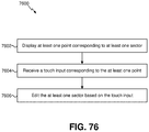
- the method may include displaying at least one touch point corresponding to the at least one sector.
- the method may also include receiving a touch input corresponding to the at least one touch point.
- the method may further include editing the at least one sector based on the touch input.
- the method may include aligning at least a part of the user interface with a reference plane.
- the reference plane may be horizontal.
- Aligning at least a part of the user interface may include mapping a two-dimensional polar plot into a three-dimensional display space.
- the physical coordinates may be earth coordinates.
- the physical coordinates may represent a physical space independent of earth coordinates.
- the coordinate system may maintain an orientation independent of electronic device orientation.
- the method may include recognizing an audio signature.
- the method may also include looking up the audio signature in a database.
- the method may further include obtaining identification information corresponding to the audio signature.
- the method may additionally include displaying the identification information on the user interface.
- the identification information may be an image of a person corresponding to the audio signature.
- the method may include providing a fixed mode and/or an editable mode.
- the method may include padding a selected sector.
- the sector selection feature may enable selection of multiple sectors at once.
- the sector editing feature may enable adjusting the sector based on single- or multi-touch input.
- the sector selection feature may be based on one or more swipe inputs.
- the one or more swipe inputs may indicate a circular region.
- the one or more swipe inputs may be a single swipe.
- the electronic device includes a display.
- the display presents a user interface.
- the user interface includes a coordinate system.
- the coordinate system corresponds to physical coordinates based on sensor data.
- the display provides a sector selection feature that allows selection of at least one sector of the coordinate system.
- a computer-program product for displaying a user interface includes a non-transitory tangible computer-readable medium with instructions.
- the instructions include code for causing an electronic device to present a user interface.
- the user interface includes a coordinate system.
- the coordinate system corresponds to physical coordinates based on sensor data.
- the instructions also include code for causing the electronic device to provide a sector selection feature that allows selection of at least one sector of the coordinate system.
- the apparatus includes means for presenting a user interface.
- the user interface includes a coordinate system.
- the coordinate system corresponds to physical coordinates based on sensor data.
- the apparatus also includes means for providing a sector selection feature that allows selection of at least one sector of the coordinate system.
- FIG. 1 shows multiple views of a multi-microphone handset
- FIG. 2A shows a far-field model of plane wave propagation relative to a microphone pair
- FIG. 2B shows multiple microphone pairs in a linear array
- FIG. 3A shows plots of unwrapped phase delay vs. frequency for four different directions of arrival (DOAs);
- FIG. 3B shows plots of wrapped phase delay vs. frequency for the same four different directions of arrival as depicted in FIG. 3A ;
- FIG. 4A shows an example of measured phase delay values and calculated values for two DOA candidates
- FIG. 4B shows a linear array of microphones arranged along the top margin of a television screen
- FIG. 5A shows an example of calculating DOA differences for a frame
- FIG. 5B shows an example of calculating a DOA estimate
- FIG. 5C shows an example of identifying a DOA estimate for each frequency
- FIG. 6A shows an example of using calculated likelihoods to identify a best microphone pair and best DOA candidate for a given frequency
- FIG. 6B shows an example of likelihood calculation
- FIG. 7 shows an example of bias removal
- FIG. 8 shows another example of bias removal
- FIG. 9 shows an example of an anglogram that plots source activity likelihood at the estimated DOA over frame and frequency
- FIG. 10A shows an example of a speakerphone application
- FIG. 10B shows a mapping of pair-wise DOA estimates to a 360° range in the plane of the microphone array
- FIGS. 11A-B show an ambiguity in the DOA estimate
- FIG. 11C shows a relation between signs of observed DOAs and quadrants of an x-y plane
- FIGS. 12A-12D show an example in which the source is located above the plane of the microphones
- FIG. 13A shows an example of microphone pairs along non-orthogonal axes
- FIG. 13B shows an example of use of the array of FIG. 13A to obtain a DOA estimate with respect to the orthogonal x and y axes;
- FIG. 13C illustrates a relation between arrival of parallel wavefronts at microphones of different arrays for examples of two different DOAs
- FIGS. 14A-14B show examples of pair-wise normalized beamformer/null beamformers (BFNFs) for a two-pair microphone array;
- BFNFs pair-wise normalized beamformer/null beamformers
- FIG. 15A shows a two-pair microphone array
- FIG. 15B shows an example of a pair-wise normalized minimum variance distortionless response (MVDR) BFNF
- FIG. 16A shows an example of a pair-wise BFNF for frequencies in which the matrix A H A is not ill-conditioned
- FIG. 16B shows examples of steering vectors
- FIG. 17 shows a flowchart of one example of an integrated method of source direction estimation as described herein;
- FIGS. 18-31 show examples of practical results of DOA estimation, source discrimination, and source tracking as described herein;
- FIG. 32A shows a telephone design
- FIGS. 32B-32D show use of such a design in various modes with corresponding visualization displays
- FIG. 33A shows a flowchart for a method M 10 according to a general configuration
- FIG. 33B shows an implementation T 12 of task T 10 ;
- FIG. 33C shows an implementation T 14 of task T 10 ;
- FIG. 33D shows a flowchart for an implementation M 20 of method M 10 ;
- FIG. 34A shows a flowchart for an implementation M 25 of method M 20 ;
- FIG. 34B shows a flowchart for an implementation M 30 of method M 10 ;
- FIG. 34C shows a flowchart for an implementation M 100 of method M 30 ;
- FIG. 35A shows a flowchart for an implementation M 110 of method M 100 ;
- FIG. 35B shows a block diagram of an apparatus A 5 according to a general configuration
- FIG. 35C shows a block diagram of an implementation A 10 of apparatus A 5 ;
- FIG. 35D shows a block diagram of an implementation A 15 of apparatus A 10 ;
- FIG. 36A shows a block diagram of an apparatus MF 5 according to a general configuration
- FIG. 36B shows a block diagram of an implementation MF 10 of apparatus MF 5 ;
- FIG. 36C shows a block diagram of an implementation MF 15 of apparatus MF 10 ;
- FIG. 37A illustrates a use of a device to represent a three-dimensional direction of arrival in a plane of the device
- FIG. 37B illustrates an intersection of the cones of confusion that represent respective responses of microphone arrays having non-orthogonal axes to a point source positioned outside the plane of the axes;
- FIG. 37C illustrates a line of intersection of the cones of FIG. 37B ;
- FIG. 38A shows a block diagram of an audio preprocessing stage
- FIG. 38B shows a block diagram of a three-channel implementation of an audio preprocessing stage
- FIG. 39A shows a block diagram of an implementation of an apparatus that includes means for indicating a direction of arrival
- FIG. 39B shows an example of an ambiguity that results from the one-dimensionality of a DOA estimate from a linear array
- FIG. 39C illustrates one example of a cone of confusion
- FIG. 40 shows an example of source confusion in a speakerphone application in which three sources are located in different respective directions relative to a device having a linear microphone array
- FIG. 41A shows a 2-D microphone array that includes two microphone pairs having orthogonal axes
- FIG. 41B shows a flowchart of a method according to a general configuration that includes tasks
- FIG. 41C shows an example of a DOA estimate shown on a display
- FIG. 42A shows one example of correspondences between the signs of 1-D estimates and corresponding quadrants of the plane defined by array axes
- FIG. 42B shows another example of correspondences between the signs of 1-D estimates and corresponding quadrants of the plane defined by array axes
- FIG. 42C shows a correspondence between the four values of the tuple (sign( ⁇ x ), sign( ⁇ y )) and the quadrants of the plane;
- FIG. 42D shows a 360-degree display according to an alternate mapping
- FIG. 43A shows an example that is similar to FIG. 41A but depicts a more general case in which the source is located above the x-y plane;
- FIG. 43B shows another example of a 2-D microphone array whose axes define an x-y plane and a source that is located above the x-y plane;
- FIG. 43C shows an example of such a general case in which a point source is elevated above the plane defined by the array axes
- FIGS. 44A-44D show a derivation of a conversion of ( ⁇ x , ⁇ y ) into an angle in the array plane;
- FIG. 44E illustrates one example of a projection p and an angle of elevation
- FIG. 45A shows a plot obtained by applying an alternate mapping
- FIG. 45B shows an example of intersecting cones of confusion associated with responses of linear microphone arrays having non-orthogonal axes x and r to a common point source
- FIG. 45C shows the lines of intersection of cones
- FIG. 46A shows an example of a microphone array
- FIG. 46B shows an example of obtaining a combined directional estimate in the x-y plane with respect to orthogonal axes x and y with observations ( ⁇ x , ⁇ r ) from an array as shown in FIG. 46A ;
- FIG. 46C illustrates one example of a projection
- FIG. 46D illustrates one example of determining a value from the dimensions of a projection vector
- FIG. 46E illustrates another example of determining a value from the dimensions of a projection vector
- FIG. 47A shows a flowchart of a method according to another general configuration that includes instances of tasks
- FIG. 47B shows a flowchart of an implementation of a task that includes subtasks
- FIG. 47C illustrates one example of an apparatus with components for performing functions corresponding to FIG. 47A ;
- FIG. 47D illustrates one example of an apparatus including means for performing functions corresponding to FIG. 47A ;
- FIG. 48A shows a flowchart of one implementation of a method that includes a task
- FIG. 48B shows a flowchart for an implementation of another method
- FIG. 49A shows a flowchart of another implementation of a method
- FIG. 49B illustrates one example of an indication of an estimated angle of elevation relative to a display plane
- FIG. 49C shows a flowchart of such an implementation of another method that includes a task
- FIGS. 50A and 50B show examples of a display before and after a rotation
- FIGS. 51A and 51B show other examples of a display before and after a rotation
- FIG. 52A shows an example in which a device coordinate system E is aligned with the world coordinate system
- FIG. 52B shows an example in which a device is rotated and the matrix F that corresponds to an orientation
- FIG. 52C shows a perspective mapping, onto a display plane of a device, of a projection of a DOA onto the world reference plane;
- FIG. 53A shows an example of a mapped display of the DOA as projected onto the world reference plane
- FIG. 53B shows a flowchart of such another implementation of a method
- FIG. 53C illustrates examples of interfaces including a linear slider potentiometer, a rocker switch and a wheel or knob;
- FIG. 54A illustrates one example of a user interface
- FIG. 54B illustrates another example of a user interface
- FIG. 54C illustrates another example of a user interface
- FIGS. 55A and 55B show a further example in which an orientation sensor is used to track an orientation of a device
- FIG. 56 is a block diagram illustrating one configuration of an electronic device in which systems and methods for mapping a source location may be implemented
- FIG. 57 is a flow diagram illustrating one configuration of a method for mapping a source location
- FIG. 58 is a block diagram illustrating a more specific configuration of an electronic device in which systems and methods for mapping a source location may be implemented;
- FIG. 59 is a flow diagram illustrating a more specific configuration of a method for mapping a source location
- FIG. 60 is a flow diagram illustrating one configuration of a method for performing an operation based on the mapping
- FIG. 61 is a flow diagram illustrating another configuration of a method for performing an operation based on the mapping
- FIG. 62 is a block diagram illustrating one configuration of a user interface in which systems and methods for displaying a user interface on an electronic device may be implemented;
- FIG. 63 is a flow diagram illustrating one configuration of a method for displaying a user interface on an electronic device
- FIG. 64 is a block diagram illustrating one configuration of a user interface in which systems and methods for displaying a user interface on an electronic device may be implemented;
- FIG. 65 is a flow diagram illustrating a more specific configuration of a method for displaying a user interface on an electronic device
- FIG. 66 illustrates examples of the user interface for displaying a directionality of at least one audio signal
- FIG. 67 illustrates another example of the user interface for displaying a directionality of at least one audio signal
- FIG. 68 illustrates another example of the user interface for displaying a directionality of at least one audio signal
- FIG. 69 illustrates another example of the user interface for displaying a directionality of at least one audio signal
- FIG. 70 illustrates another example of the user interface for displaying a directionality of at least one audio signal
- FIG. 71 illustrates an example of a sector selection feature of the user interface
- FIG. 72 illustrates another example of the sector selection feature of the user interface
- FIG. 73 illustrates another example of the sector selection feature of the user interface
- FIG. 74 illustrates more examples of the sector selection feature of the user interface
- FIG. 75 illustrates more examples of the sector selection feature of the user interface
- FIG. 76 is a flow diagram illustrating one configuration of a method for editing a sector
- FIG. 77 illustrates examples of a sector editing feature of the user interface
- FIG. 78 illustrates more examples of the sector editing feature of the user interface
- FIG. 79 illustrates more examples of the sector editing feature of the user interface
- FIG. 80 illustrates more examples of the sector editing feature of the user interface
- FIG. 81 illustrates more examples of the sector editing feature of the user interface
- FIG. 82 illustrates an example of the user interface with a coordinate system oriented independent of electronic device orientation
- FIG. 83 illustrates another example of the user interface with the coordinate system oriented independent of electronic device orientation
- FIG. 84 illustrates another example of the user interface with the coordinate system oriented independent of electronic device orientation
- FIG. 85 illustrates another example of the user interface with the coordinate system oriented independent of electronic device orientation
- FIG. 86 illustrates more examples of the user interface with the coordinate system oriented independent of electronic device orientation
- FIG. 87 illustrates another example of the user interface with the coordinate system oriented independent of electronic device orientation
- FIG. 88 is a block diagram illustrating another configuration of the user interface in which systems and methods for displaying a user interface on an electronic device may be implemented;
- FIG. 89 is a flow diagram illustrating another configuration of a method for displaying a user interface on an electronic device
- FIG. 90 illustrates an example of the user interface coupled to a database
- FIG. 91 is a flow diagram illustrating another configuration of a method for displaying a user interface on an electronic device
- FIG. 92 is a block diagram illustrating one configuration of a wireless communication device in which systems and methods for mapping a source location may be implemented;
- FIG. 93 illustrates various components that may be utilized in an electronic device.
- FIG. 94 illustrates another example of a user interface.
- the 3rd Generation Partnership Project (3GPP) is a collaboration between groups of telecommunications associations that aims to define a globally applicable 3rd generation (3G) mobile phone specification.
- 3GPP Long Term Evolution (LTE) is a 3GPP project aimed at improving the Universal Mobile Telecommunications System (UMTS) mobile phone standard.
- the 3GPP may define specifications for the next generation of mobile networks, mobile systems and mobile devices.
- the systems and methods disclosed herein may be described in terms of one or more specifications, such as the 3GPP Release-8 (Rel-8), 3GPP Release-9 (Rel-9), 3GPP Release-10 (Rel-10), LTE, LTE-Advanced (LTE-A), Global System for Mobile Communications (GSM), General Packet Radio Service (GPRS), Enhanced Data Rates for GSM Evolution (EDGE), Time Division Long-Term Evolution (TD-LTE), Time Division Synchronous Code Division Multiple Access (TD-SCDMA), Frequency-Division Duplexing Long-Term Evolution (FDD-LTE), UMTS, GSM EDGE Radio Access Network (GERAN), Global Positioning System (GPS), etc.
- 3GPP Release-8 (Rel-8), 3GPP Release-9 (Rel-9), 3GPP Release-10 (Rel-10)
- LTE LTE-Advanced (LTE-A)
- GSM Global System for Mobile Communications
- GPRS General Packet Radio Service
- EDGE Time Division Long-Term Evolution
- the term electronic device may be used to refer to a User Equipment (UE).
- the term base station may be used to refer to at least one of the terms Node B, Evolved Node B (eNB), Home Evolved Node B (HeNB), etc.
- the term “signal” is used herein to indicate any of its ordinary meanings, including a state of a memory location (or set of memory locations) as expressed on a wire, bus, or other transmission medium.
- the term “generating” is used herein to indicate any of its ordinary meanings, such as computing or otherwise producing.
- the term “calculating” is used herein to indicate any of its ordinary meanings, such as computing, evaluating, estimating and/or selecting from a plurality of values.
- the term “obtaining” is used to indicate any of its ordinary meanings, such as calculating, deriving, receiving (e.g., from an external device), and/or retrieving (e.g., from an array of storage elements).
- the term “selecting” is used to indicate any of its ordinary meanings, such as identifying, indicating, applying, and/or using at least one, and fewer than all, of a set of two or more.
- the term “determining” is used to indicate any of its ordinary meanings, such as deciding, establishing, concluding, calculating, selecting and/or evaluating.
- the term “in response to” is used to indicate any of its ordinary meanings, including “in response to at least.” Unless otherwise indicated, the terms “at least one of A, B, and C” and “one or more of A, B, and C” indicate “A and/or B and/or C.”
- references to a “location” of a microphone of a multi-microphone audio sensing device indicate the location of the center of an acoustically sensitive face of the microphone, unless otherwise indicated by the context.
- the term “channel” is used at times to indicate a signal path and at other times to indicate a signal carried by such a path, according to the particular context.
- the term “series” is used to indicate a sequence of two or more items.
- the term “logarithm” is used to indicate the base-ten logarithm, although extensions of such an operation to other bases are within the scope of this disclosure.
- frequency component is used to indicate one among a set of frequencies or frequency bands of a signal, such as a sample (or “bin”) of a frequency domain representation of the signal (e.g., as produced by a fast Fourier transform) or a subband of the signal (e.g., a Bark scale or mel scale subband).
- a sample or “bin”
- a subband of the signal e.g., a Bark scale or mel scale subband
- any disclosure of an operation of an apparatus having a particular feature is also expressly intended to disclose a method having an analogous feature (and vice versa), and any disclosure of an operation of an apparatus according to a particular configuration is also expressly intended to disclose a method according to an analogous configuration (and vice versa).
- configuration may be used in reference to a method, apparatus and/or system as indicated by its particular context.
- method method
- process processing
- procedure and “technique”
- a “task” having multiple subtasks is also a method.
- apparatus and “device” are also used generically and interchangeably unless otherwise indicated by the particular context.
- a method of processing a multichannel signal includes calculating, for each of a plurality of different frequency components of the multichannel signal, a difference between a phase of the frequency component in each of a first pair of channels of the multichannel signal, to obtain a plurality of phase differences.
- This method also includes estimating an error, for each of a plurality of candidate directions, between the candidate direction and a vector that is based on the plurality of phase differences.
- This method also includes selecting, from among the plurality of candidate directions, a candidate direction that corresponds to the minimum among the estimated errors.
- each of said first pair of channels is based on a signal produced by a corresponding one of a first pair of microphones, and at least one of the different frequency components has a wavelength that is less than twice the distance between the microphones of the first pair.
- the near-field may be defined as that region of space that is less than one wavelength away from a sound receiver (e.g., a microphone array).
- a sound receiver e.g., a microphone array.
- the distance to the boundary of the region varies inversely with frequency. At frequencies of two hundred, seven hundred, and two thousand hertz, for example, the distance to a one-wavelength boundary is about 170, forty-nine, and seventeen centimeters, respectively.
- the near-field/far-field boundary may be at a particular distance from the microphone array (e.g., fifty centimeters from a microphone of the array or from the centroid of the array, or one meter or 1.5 meters from a microphone of the array or from the centroid of the array).
- FIG. 1 shows an example of a multi-microphone handset H 100 (e.g., a multi-microphone device) that includes a first microphone pair MV 10 - 1 , MV 10 - 3 whose axis is in a left-right direction of a front face of the device, and a second microphone pair MV 10 - 1 , MV 10 - 2 whose axis is in a front-back direction (i.e., orthogonal to the front face).
- a front-back direction i.e., orthogonal to the front face.
- the front-back pair may be used to resolve an ambiguity between front and back directions that the left-right pair typically cannot resolve on its own.
- the handset H 100 may include one or more loudspeakers LS 10 , L 20 L, LS 20 R, a touchscreen TS 10 , a lens L 10 and/or one or more additional microphones ME 10 , MR 10 .
- audio sensing devices that may be implemented to include a multi-microphone array and to perform a method as described herein include portable computing devices (e.g., laptop computers, notebook computers, netbook computers, ultra-portable computers, tablet computers, mobile Internet devices, smartbooks, smartphones, etc.), audio- or video-conferencing devices, and display screens (e.g., computer monitors, television sets).
- portable computing devices e.g., laptop computers, notebook computers, netbook computers, ultra-portable computers, tablet computers, mobile Internet devices, smartbooks, smartphones, etc.
- audio- or video-conferencing devices e.g., computer monitors, television sets.
- a device as shown in FIG. 1 may be configured to determine the direction of arrival (DOA) of a source signal by measuring a difference (e.g., a phase difference) between the microphone channels for each frequency bin to obtain an indication of direction, and averaging the direction indications over all bins to determine whether the estimated direction is consistent over all bins.
- DOA direction of arrival
- the range of frequency bins that may be available for tracking is typically constrained by the spatial aliasing frequency for the microphone pair. This upper limit may be defined as the frequency at which the wavelength of the signal is twice the distance, d, between the microphones.
- Such an approach may not support accurate tracking of source DOA beyond one meter and typically may support only a low DOA resolution.
- dependence on a front-back pair to resolve ambiguity may be a significant constraint on the microphone placement geometry, as placing the device on a surface may effectively occlude the front or back microphone.
- Such an approach also typically uses only one fixed pair for tracking.
- the multi-microphone device may be placed arbitrarily (e.g., on a table for a conference call, on a car seat, etc.) and track and/or enhance the voices of individual speakers.
- Such an approach may be capable of dealing with an arbitrary target speaker position with respect to an arbitrary orientation of available microphones. It may also be desirable for such an approach to provide instantaneous multi-speaker tracking/separating capability.
- the current state of the art is a single-microphone approach.
- the multi-microphone device in such an application may include an array mounted on a television or set-top box, which may be used to support telephony. Examples include the array of a Kinect device (Microsoft Corp., Redmond, Wash.) and arrays from Skype (Microsoft Skype Division) and Samsung Electronics (Seoul, KR).
- Kinect device Microsoft Corp., Redmond, Wash.
- Skype Microsoft Skype Division
- Samsung Electronics Samsung Electronics
- the systems and methods disclosed herein may be implemented for such a generic speakerphone application or far-field application. Such an approach may be implemented to operate without a microphone placement constraint. Such an approach may also be implemented to track sources using available frequency bins up to Nyquist frequency and down to a lower frequency (e.g., by supporting use of a microphone pair having a larger inter-microphone distance). Rather than being limited to a single pair for tracking, such an approach may be implemented to select a best pair among all available pairs. Such an approach may be used to support source tracking even in a far-field scenario, up to a distance of three to five meters or more, and to provide a much higher DOA resolution. Other potential features include obtaining an exact 2-D representation of an active source. For best results, it may be desirable that each source is a sparse broadband audio source, and that each frequency bin is mostly dominated by no more than one source.
- FIG. 33A shows a flowchart for a method M 10 according to a general configuration that includes tasks T 10 , T 20 and T 30 .
- Task T 10 calculates a difference between a pair of channels of a multichannel signal (e.g., in which each channel is based on a signal produced by a corresponding microphone).
- task T 20 calculates a corresponding directional error that is based on the calculated difference.
- task T 30 selects a candidate direction.
- Method M 10 may be configured to process the multichannel signal as a series of segments. Typical segment lengths range from about five or ten milliseconds to about forty or fifty milliseconds, and the segments may be overlapping (e.g., with adjacent segments overlapping by 25% or 50%) or non-overlapping. In one particular example, the multichannel signal is divided into a series of non-overlapping segments or “frames,” each having a length of ten milliseconds. In another particular example, each frame has a length of twenty milliseconds. A segment as processed by method M 10 may also be a segment (i.e., a “subframe”) of a larger segment as processed by a different operation, or vice versa.
- a segment i.e., a “subframe”
- differences between the channels include a gain difference or ratio, a time difference of arrival, and a phase difference.
- task T 10 may be implemented to calculate the difference between the channels of a pair as a difference or ratio between corresponding gain values of the channels (e.g., a difference in magnitude or energy).
- FIG. 33B shows such an implementation T 12 of task T 10 .
- Task T 12 may be implemented to calculate measures of the gain of a segment of the multichannel signal in the time domain (e.g., for each of a plurality of subbands of the signal) or in a frequency domain (e.g., for each of a plurality of frequency components of the signal in a transform domain, such as a fast Fourier transform (FFT), discrete cosine transform (DCT), or modified DCT (MDCT) domain).
- FFT fast Fourier transform
- DCT discrete cosine transform
- MDCT modified DCT
- gain measures include, without limitation, the following: total magnitude (e.g., sum of absolute values of sample values), average magnitude (e.g., per sample), root mean square (RMS) amplitude, median magnitude, peak magnitude, peak energy, total energy (e.g., sum of squares of sample values), and average energy (e.g., per sample).
- total magnitude e.g., sum of absolute values of sample values
- average magnitude e.g., per sample
- RMS root mean square
- the responses of the two microphone channels may be calibrated relative to each other. It may be desirable to apply a low-pass filter to the multichannel signal such that calculation of the gain measure is limited to an audio-frequency component of the multichannel signal.
- Task T 12 may be implemented to calculate a difference between gains as a difference between corresponding gain measure values for each channel in a logarithmic domain (e.g., values in decibels) or, equivalently, as a ratio between the gain measure values in a linear domain.
- a logarithmic domain e.g., values in decibels
- a gain difference of zero may be taken to indicate that the source is equidistant from each microphone (i.e., located in a broadside direction of the pair), a gain difference with a large positive value may be taken to indicate that the source is closer to one microphone (i.e., located in one endfire direction of the pair), and a gain difference with a large negative value may be taken to indicate that the source is closer to the other microphone (i.e., located in the other endfire direction of the pair).
- task T 10 from FIG. 33A may be implemented to perform a cross-correlation on the channels to determine the difference (e.g., calculating a time-difference-of-arrival based on a lag between channels of the multichannel signal).
- task T 10 is implemented to calculate the difference between the channels of a pair as a difference between the phase of each channel (e.g., at a particular frequency component of the signal).
- FIG. 33C shows such an implementation T 14 of task T 10 . As discussed below, such calculation may be performed for each among a plurality of frequency components.
- phase delay For a signal received by a pair of microphones directly from a point source in a particular direction of arrival (DOA) relative to the axis of the microphone pair, the phase delay differs for each frequency component and also depends on the spacing between the microphones.
- the observed value of the phase delay at a particular frequency component may be calculated as the inverse tangent (also called the arctangent) of the ratio of the imaginary term of the complex FFT coefficient to the real term of the complex FFT coefficient.
- the phase delay value ⁇ f for a source S 01 for at least one microphone MC 10 , MC 20 at a particular frequency, f may be related to source DOA under a far-field (i.e., plane-wave) assumption as
- ⁇ f 2 ⁇ ⁇ ⁇ ⁇ f ⁇ ⁇ d ⁇ ⁇ sin ⁇ ⁇ ⁇ c , where d denotes the distance between the microphones MC 10 , MC 20 (in meters), ⁇ denotes the angle of arrival (in radians) relative to a direction that is orthogonal to the array axis, f denotes frequency (in Hz), and c denotes the speed of sound (in m/s).
- the DOA estimation principles described herein may be extended to multiple microphone pairs in a linear array (e.g., as shown in FIG. 2B ). For the ideal case of a single point source with no reverberation, the ratio of phase delay to frequency ⁇ f will have the same value
- the DOA, ⁇ , relative to a microphone pair is a one-dimensional measurement that defines the surface of a cone in space (e.g., such that the axis of the cone is the axis of the array).
- the spatial aliasing frequency for the microphone pair which may be defined as the frequency at which the wavelength of the signal is twice the distance d between the microphones.
- Spatial aliasing causes phase wrapping, which puts an upper limit on the range of frequencies that may be used to provide reliable phase delay measurements for a particular microphone pair.
- FIG. 3A shows plots of unwrapped phase delay vs. frequency for four different DOAs D 10 , D 20 , D 30 , D 40 .
- FIG. 3B shows plots of wrapped phase delay vs. frequency for the same DOAs D 10 , D 20 , D 30 , D 40 , where the initial portion of each plot (i.e., until the first wrapping occurs) are shown in bold. Attempts to extend the useful frequency range of phase delay measurement by unwrapping the measured phase are typically unreliable.
- Task T 20 may be implemented to calculate the directional error in terms of phase difference.
- FIG. 4A shows such an example that includes angle vs. frequency plots of the (noisy) measured phase delay values MPD 10 and the phase delay values PD 10 , PD 20 for two DOA candidates of the inventory (solid and dashed lines), where phase is wrapped to the range of pi to minus pi.
- the DOA candidate that is best matched to the signal as observed may then be determined by calculating a corresponding directional error for each DOA candidate, ⁇ i , and identifying the DOA candidate value that corresponds to the minimum among these directional errors.
- Such a directional error may be calculated, for example, as an error, e ph_k , between the phase delay values, ⁇ k_f , for the k-th DOA candidate and the observed phase delay values ⁇ ob_f .
- the error, e ph_k is expressed as ⁇ ob_f ⁇ k_f ⁇ f 2 over a desired range or other set F of frequency components, i.e. as the sum
- phase delay values, ⁇ k_f for each DOA candidate, ⁇ k , may be calculated before run-time (e.g., during design or manufacture), according to known values of c and d and the desired range of frequency components f, and retrieved from storage during use of the device.
- Such a pre-calculated inventory may be configured to support a desired angular range and resolution (e.g., a uniform resolution, such as one, two, five, six, ten, or twelve degrees; or a desired non-uniform resolution) and a desired frequency range and resolution (which may also be uniform or non-uniform).
- a desired angular range and resolution e.g., a uniform resolution, such as one, two, five, six, ten, or twelve degrees; or a desired non-uniform resolution
- a desired frequency range and resolution which may also be uniform or non-uniform
- the directional error (e.g., e ph_f ,e ph_k ) across as many frequency bins as possible to increase robustness against noise.
- the error calculation may include terms from frequency bins that are beyond the spatial aliasing frequency.
- the maximum frequency bin may be limited by other factors, which may include available memory, computational complexity, strong reflection by a rigid body (e.g., an object in the environment, a housing of the device) at high frequencies, etc.
- a speech signal is typically sparse in the time-frequency domain. If the sources are disjoint in the frequency domain, then two sources can be tracked at the same time. If the sources are disjoint in the time domain, then two sources can be tracked at the same frequency. It may be desirable for the array to include a number of microphones that is at least equal to the number of different source directions to be distinguished at any one time.
- the microphones may be omnidirectional (e.g., as may be typical for a cellular telephone or a dedicated conferencing device) or directional (e.g., as may be typical for a device such as a set-top box).
- Such multichannel processing is generally applicable, for example, to source tracking for speakerphone applications.
- Such a technique may be used to calculate a DOA estimate for a frame of the received multichannel signal.
- Such an approach may calculate, at each frequency bin, the error for each candidate angle with respect to the observed angle, which is indicated by the phase delay.
- the target angle at that frequency bin is the candidate having the minimum error.
- the error is then summed across the frequency bins to obtain a measure of likelihood for the candidate.
- one or more of the most frequently occurring target DOA candidates across all frequency bins is identified as the DOA estimate (or estimates) for a given frame.
- Such a method may be applied to obtain instantaneous tracking results (e.g., with a delay of less than one frame).
- the delay is dependent on the FFT size and the degree of overlap. For example, for a 512-point FFT with a 50% overlap and a sampling frequency of 16 kilohertz (kHz), the resulting 256-sample delay corresponds to sixteen milliseconds.
- Such a method may be used to support differentiation of source directions typically up to a source-array distance of two to three meters, or even up to five meters.
- the error may also be considered as a variance (i.e., the degree to which the individual errors deviate from an expected value). Conversion of the time-domain received signal into the frequency domain (e.g., by applying an FFT) has the effect of averaging the spectrum in each bin. This averaging is even more obvious if a subband representation is used (e.g., mel scale or Bark scale). Additionally, it may be desirable to perform time-domain smoothing on the DOA estimates (e.g., by applying a recursive smoother, such as a first-order infinite-impulse-response filter). It may be desirable to reduce the computational complexity of the error calculation operation (e.g., by using a search strategy, such as a binary tree, and/or applying known information, such as DOA candidate selections from one or more previous frames).
- a search strategy such as a binary tree
- An expression of directional error in terms of DOA may be derived by expressing wrapped phase delay at frequency f (e.g., the observed phase delay, ⁇ ob_f , as a function ⁇ f_wr of the DOA, ⁇ , of the signal, such as
- ⁇ f ⁇ ⁇ _ ⁇ ⁇ un ⁇ ( ⁇ ) - 2 ⁇ ⁇ ⁇ ⁇ ⁇ f ⁇ d ⁇ ⁇ sin ⁇ ⁇ ⁇ c , except near discontinuities that are due to phase wrapping.
- or e ph_f_k ( ⁇ f_wr ( ⁇ ob ) ⁇ f_wr ( ⁇ k )) 2 ⁇ ( ⁇ f_un ( ⁇ ob ) ⁇ f_un ( ⁇ k )) 2 , where the difference between the observed and candidate phase delay at frequency f is expressed in terms of observed DOA at frequency f, ⁇ ob_f , and candidate DOA, ⁇ k , as
- ⁇ f ⁇ ⁇ _ ⁇ ⁇ un ⁇ ( ⁇ ob ) - ⁇ f ⁇ ⁇ _ ⁇ ⁇ un ⁇ ( ⁇ k ) - 2 ⁇ ⁇ ⁇ ⁇ ⁇ fd c ⁇ ( sin ⁇ ⁇ ⁇ ob ⁇ ⁇ _ ⁇ ⁇ f - sin ⁇ ⁇ ⁇ k ) .
- This expression may be used (e.g., in task T 20 ), with the assumed equivalence of observed wrapped phase delay to unwrapped phase delay, to express the directional error in terms of DOA (e DOA_f_k ,e DOA_k ) rather than phase delay (e ph_f_k ,e ph_k ):
- task T 20 may be desirable to implement task T 20 to perform such an expansion using a second-order approximation instead, as in the following:
- FIGS. 5A-5C depict a plurality of frames 502 .
- a directional error based on a difference between observed and candidate DOA for a given frame of the received signal may be calculated in such manner (e.g., by task T 20 ) at each of a plurality of frequencies f of the received microphone signals (e.g., ⁇ f ⁇ F) and for each of a plurality of DOA candidates ⁇ k .
- e s (n) ⁇ e s (n+1)+(1 ⁇ )e(n) (also known as a first-order IIR or recursive filter), where e s (n ⁇ 1) denotes the smoothed directional error for the previous frame, e s (n) denotes the current unsmoothed value of the directional error, e s (n) denotes the current smoothed value of the directional error, and ⁇ is a smoothing factor whose value may be selected from the range from zero (no smoothing) to one (no updating).
- Typical values for smoothing factor ⁇ include 0.1, 0.2, 0.25, 0.3, 0.4 and 0.5. It is typical, but not necessary, for such an implementation of task T 20 to use the same value of ⁇ to smooth directional errors that correspond to different frequency components. Similarly, it is typical, but not necessary, for such an implementation of task T 20 to use the same value of ⁇ to smooth directional errors that correspond to different candidate directions.
- a DOA estimate for a given frame may be determined by summing the squared differences for each candidate across all frequency bins in the frame to obtain a directional error (e.g., e ph_k or e DOA_k ) and selecting the DOA candidate having the minimum error.
- a directional error e.g., e ph_k or e DOA_k
- FIG. 5C such differences may be used to identify the best-matched (i.e. minimum squared difference) DOA candidate at each frequency.
- a DOA estimate for the frame may then be determined as the most
- task T 30 selects a candidate direction for the frequency component. For example, task T 30 may be implemented to select the candidate direction associated with the lowest among the K directional errors produced by task T 20 . In another example, task T 30 is implemented to calculate a likelihood based on each directional error and to select the candidate direction associated with the highest likelihood.
- an error term 604 may be calculated for each candidate angle 606 , 1 , and each of a set F of frequencies for each frame 608 , k. It may be desirable to indicate a likelihood of source activity in terms of a calculated DOA difference or error term 604 .
- a likelihood L may be expressed, for a particular frame, frequency and angle, as
- Speech tends to be sparse in both time and frequency, such that a sum over a set of frequencies F may include results from bins that are dominated by noise. It may be desirable to include a bias term ⁇ , as in the following expression:
- the bias term which may vary over frequency and/or time, may be based on an assumed distribution of the noise (e.g., Gaussian). Additionally or alternatively, the bias term may be based on an initial estimate of the noise (e.g., from a noise-only initial frame). Additionally or alternatively, the bias term may be updated dynamically based on information from noise-only frames, as indicated, for example, by a voice activity detection module.
- FIGS. 7 and 8 show examples of plots of likelihood before and after bias removal, respectively. In FIG.
- the frame number 710 the frame number 710 , an angle of arrival 712 and an amplitude 714 of a signal are illustrated.
- the frame number 810 an angle of arrival 812 and an amplitude 814 of a signal are illustrated.
- the frequency-specific likelihood results may be projected onto a (frame, angle) plane (e.g., as shown in FIG. 8 ) to obtain a DOA estimation per frame
- ⁇ est ⁇ ⁇ _ ⁇ ⁇ k max i ⁇ ⁇ f ⁇ F ⁇ L ⁇ ( i , f , k ) that is robust to noise and reverberation because only target-dominant frequency bins contribute to the estimate.
- terms in which the error is large may have values that approach zero and thus become less significant to the estimate. If a directional source is dominant in some frequency bins, the error value at those frequency bins may be nearer to zero for that angle. Also, if another directional source is dominant in other frequency bins, the error value at the other frequency bins may be nearer to zero for the other angle.
- the likelihood results may also be projected onto a (frame, frequency) plane as shown in the bottom panel 918 of FIG. 9 to indicate likelihood information per frequency bin, based on directional membership (e.g., for voice activity detection).
- the bottom panel 918 shows, for each frequency and frame, the corresponding likelihood for the estimated DOA
- This likelihood may be used to indicate likelihood of speech activity. Additionally or alternatively, such information may be used, for example, to support time- and/or frequency-selective masking of the received signal by classifying frames and/or frequency components according to their directions of arrival.
- An anglogram representation is similar to a spectrogram representation. As shown in the top panel 916 of FIG. 9 , a spectrogram may be obtained by plotting, at each frame, the magnitude of each frequency component. An anglogram may be obtained by plotting, at each frame, a likelihood of the current DOA candidate at each frequency.
- FIG. 33D shows a flowchart for an implementation M 20 of method M 10 that includes tasks T 100 , T 200 and T 300 .
- Such a method may be used, for example, to select a candidate direction of arrival of a source signal, based on information from a pair of channels of a multichannel signal, for each of a plurality F of frequency components of the multichannel signal.
- task T 100 calculates a difference between the pair of channels.
- Task T 100 may be implemented, for example, to perform a corresponding instance of task T 10 (e.g., task T 12 or T 14 ) for each among the plurality F of frequency components.
- task T 200 calculates a plurality of directional errors.
- Task T 200 may be implemented to calculate K directional errors for each frequency component.
- task T 200 may be implemented to perform a corresponding instance of task T 20 for each among the plurality F of frequency components.
- task T 200 may be implemented to calculate K directional errors for each among one or more of the frequency components, and to calculate a different number (e.g., more or less than K) directional errors for each among a different one or more among the frequency components.
- task T 300 For each among the plurality F of frequency components, task T 300 selects a candidate direction. Task T 300 may be implemented to perform a corresponding instance of task T 30 for each among the plurality F of frequency components.
- the energy spectrum of voiced speech tends to have local peaks at harmonics of the pitch frequency.
- the energy spectrum of background noise tends to be relatively unstructured. Consequently, components of the input channels at harmonics of the pitch frequency may be expected to have a higher signal-to-noise ratio (SNR) than other components. It may be desirable to configure method M 20 to consider only frequency components that correspond to multiples of an estimated pitch frequency.
- Typical pitch frequencies range from about 70 to 100 Hz for a male speaker to about 150 to 200 Hz for a female speaker.
- the current pitch frequency may be estimated by calculating the pitch period as the distance between adjacent pitch peaks (e.g., in a primary microphone channel).
- a sample of an input channel may be identified as a pitch peak based on a measure of its energy (e.g., based on a ratio between sample energy and frame average energy) and/or a measure of how well a neighborhood of the sample is correlated with a similar neighborhood of a known pitch peak.
- a pitch estimation procedure is described, for example, in section 4.6.3 (pp. 4-44 to 4-49) of EVRC (Enhanced Variable Rate Codec) document C.S0014-C, available online at www.3gpp.org.
- a current estimate of the pitch frequency (e.g., in the form of an estimate of the pitch period or “pitch lag”) will typically already be available in applications that include speech encoding and/or decoding (e.g., voice communications using codecs that include pitch estimation, such as code-excited linear prediction (CELP) and prototype waveform interpolation (PWI)).
- CELP code-excited linear prediction
- PWI prototype waveform interpolation
- task T 100 may be desirable, for example, to configure task T 100 such that at least twenty-five, fifty or seventy-five percent of the calculated channel differences (e.g., phase differences) correspond to multiples of an estimated pitch frequency.
- the same principle may be applied to other desired harmonic signals as well.
- task T 100 is implemented to calculate phase differences for each of the frequency components of at least a subband of the channel pair, and task T 200 is implemented to calculate directional errors based on only those phase differences which correspond to multiples of an estimated pitch frequency.
- FIG. 34A shows a flowchart for an implementation M 25 of method M 20 that includes task T 400 .
- Such a method may be used, for example, to indicate a direction of arrival of a source signal, based on information from a pair of channels of a multichannel signal.
- task T 400 Based on the F candidate direction selections produced by task T 300 , task T 400 indicates a direction of arrival.
- task T 400 may be implemented to indicate the most frequently selected among the F candidate directions as the direction of arrival.
- task T 400 may be implemented to indicate more than one direction of arrival (e.g., to indicate a direction for each among more than one source).
- Method M 25 may be iterated over time to indicate one or more directions of arrival for each of a sequence of frames of the multichannel signal.
- a microphone pair having a large spacing is typically not suitable for high frequencies, because spatial aliasing begins at a low frequency for such a pair.
- a DOA estimation approach as described herein allows the use of phase delay measurements beyond the frequency at which phase wrapping begins, and even up to the Nyquist frequency (i.e., half of the sampling rate).
- By relaxing the spatial aliasing constraint such an approach enables the use of microphone pairs having larger inter-microphone spacing.
- use of a larger array typically extends the range of useful phase delay measurements into lower frequencies as well.
- the DOA estimation principles described herein may be extended to multiple microphone pairs MC 10 a , MC 10 b , MC 10 c in a linear array (e.g., as shown in FIG. 2B ).
- the multiple microphone pairs of a linear array will have essentially the same DOA. Accordingly, one option is to estimate the DOA as an average of the DOA estimates from two or more pairs in the array. However, an averaging scheme may be affected by mismatch of even a single one of the pairs, which may reduce DOA estimation accuracy. Alternatively, it may be desirable to select, from among two or more pairs of microphones of the array, the best microphone pair for each frequency (e.g., the pair that gives the minimum error e i at that frequency), such that different microphone pairs may be selected for different frequency bands. At the spatial aliasing frequency of a microphone pair, the error will be large.
- the best pair for each axis is selected by calculating, for each frequency f, P ⁇ I values, where P is the number of pairs, I is the size of the inventory, and each value e pi is the squared absolute difference between the observed angle ⁇ pf (for pair p and frequency f) and the candidate angle ⁇ if .
- the pair p that corresponds to the lowest error value e pi is selected. This error value also indicates the best DOA candidate ⁇ if at frequency f (as shown in FIG. 6A ).
- FIG. 34B shows a flowchart for an implementation M 30 of method M 10 that includes an implementation T 150 of task T 10 and an implementation T 250 of task T 20 .
- Method M 30 may be used, for example, to indicate a candidate direction for a frequency component of the multichannel signal (e.g., at a particular frame).
- task T 250 For each among a plurality P of pairs of channels of the multichannel signal, task T 250 calculates a plurality of directional errors.
- Task T 250 may be implemented to calculate K directional errors for each channel pair.
- task T 250 may be implemented to perform a corresponding instance of task T 20 for each among the plurality P of channel pairs.
- task T 250 may be implemented to calculate K directional errors for each among one or more of the channel pairs, and to calculate a different number (e.g., more or less than K) directional errors for each among a different one or more among the channel pairs.
- Method M 30 also includes a task T 35 that selects a candidate direction, based on the pluralities of directional errors.
- task T 35 may be implemented to select the candidate direction that corresponds to the lowest among the directional errors.
- FIG. 34C shows a flowchart for an implementation M 100 of method M 30 that includes an implementation T 170 of tasks T 100 and T 150 , an implementation T 270 of tasks T 200 and T 250 , and an implementation T 350 of task T 35 .
- Method M 100 may be used, for example, to select a candidate direction for each among a plurality F of frequency components of the multichannel signal (e.g., at a particular frame).
- task T 170 calculates a plurality P of differences, where each among the plurality P of differences corresponds to a different pair of channels of the multichannel signal and is a difference between the 21 channels (e.g., a gain-based or phase-based difference).
- task T 270 calculates a plurality of directional errors for each among the plurality P of pairs.
- task T 270 may be implemented to calculate, for each of the frequency components, K directional errors for each of the P pairs, or a total of P ⁇ K directional errors for each frequency component.
- task T 350 selects a corresponding candidate direction.
- FIG. 35A shows a flowchart for an implementation M 110 of method M 100 .
- the implementation M 110 may include tasks T 170 , T 270 , T 350 and T 400 that may be examples of corresponding elements described in connection with at least one of FIG. 34A and FIG. 34C .
- FIG. 35B shows a block diagram of an apparatus A 5 according to a general configuration that includes an error calculator 200 and a selector 300 .
- Error calculator 200 is configured to calculate, for a calculated difference between a pair of channels of a multichannel signal and for each among a plurality K of candidate directions, a corresponding directional error that is based on the calculated difference (e.g., as described herein with reference to implementations of task T 20 ).
- Selector 300 is configured to select a candidate direction, based on the corresponding directional error (e.g., as described herein with reference to implementations of task T 30 ).
- FIG. 35C shows a block diagram of an implementation A 10 of apparatus A 5 that includes a difference calculator 100 .
- Apparatus A 10 may be implemented, for example, to perform an instance of method M 10 , M 20 , M 30 , and/or M 100 as described herein.
- Calculator 100 is configured to calculate a difference (e.g., a gain-based or phase-based difference) between a pair of channels of a multichannel signal (e.g., as described herein with reference to implementations of task T 10 ).
- Calculator 100 may be implemented, for example, to calculate such a difference for each among a plurality F of frequency components of the multichannel signal.
- calculator 100 may also be implemented to apply a subband filter bank to the signal and/or to calculate a frequency transform of each channel (e.g., a fast Fourier transform (FFT) or modified discrete cosine transform (MDCT)) before calculating the difference.
- a frequency transform of each channel e.g., a fast Fourier transform (FFT) or modified discrete cosine transform (MDCT)
- FIG. 35D shows a block diagram of an implementation A 15 of apparatus A 10 that includes an indicator 400 .
- Indicator 400 is configured to indicate a direction of arrival, based on a plurality of candidate direction selections produced by selector 300 (e.g., as described herein with reference to implementations of task T 400 ).
- Apparatus A 15 may be implemented, for example, to perform an instance of method M 25 and/or M 110 as described herein.
- FIG. 36A shows a block diagram of an apparatus MF 5 according to a general configuration.
- Apparatus MF 5 includes means F 20 for calculating, for a calculated difference between a pair of channels of a multichannel signal and for each among a plurality K of candidate directions, a corresponding directional error or fitness measure that is based on the calculated difference (e.g., as described herein with reference to implementations of task T 20 ).
- Apparatus MF 5 also includes means F 30 for selecting a candidate direction, based on the corresponding directional error (e.g., as described herein with reference to implementations of task T 30 ).
- FIG. 36B shows a block diagram of an implementation MF 10 of apparatus MF 5 that includes means F 10 for calculating a difference (e.g., a gain-based or phase-based difference) between a pair of channels of a multichannel signal (e.g., as described herein with reference to implementations of task T 10 ).
- Means F 10 may be implemented, for example, to calculate such a difference for each among a plurality F of frequency components of the multichannel signal.
- means F 10 may also be implemented to include means for performing a subband analysis and/or calculating a frequency transform of each channel (e.g., a fast Fourier transform (FFT) or modified discrete cosine transform (MDCT)) before calculating the difference.
- Apparatus MF 10 may be implemented, for example, to perform an instance of method M 10 , M 20 , M 30 , and/or M 100 as described herein.
- FIG. 36C shows a block diagram of an implementation MF 15 of apparatus MF 10 that includes means F 40 for indicating a direction of arrival, based on a plurality of candidate direction selections produced by means F 30 (e.g., as described herein with reference to implementations of task T 400 ).
- Apparatus MF 15 may be implemented, for example, to perform an instance of method M 25 and/or M 110 as described herein.
- the signals received by a microphone pair may be processed as described herein to provide an estimated DOA, over a range of up to 180 degrees, with respect to the axis of the microphone pair.
- the desired angular span and resolution may be arbitrary within that range (e.g. uniform (linear) or non-uniform (nonlinear), limited to selected sectors of interest, etc.). Additionally or alternatively, the desired frequency span and resolution may be arbitrary (e.g. linear, logarithmic, mel-scale, Bark-scale, etc.).
- each DOA estimate between 0 and +/ ⁇ 90 degrees from a microphone pair indicates an angle relative to a plane that is orthogonal to the axis of the pair.
- Such an estimate describes a cone around the axis of the pair, and the actual direction of the source along the surface of this cone is indeterminate.
- a DOA estimate from a single microphone pair does not indicate whether the source is in front of or behind (or above or below) the microphone pair. Therefore, while more than two microphones may be used in a linear array to improve DOA estimation performance across a range of frequencies, the range of DOA estimation supported by a linear array is typically limited to 180 degrees.
- the DOA estimation principles described herein may also be extended to a two-dimensional (2-D) array of microphones.
- a 2-D array may be used to extend the range of source DOA estimation up to a full 360° (e.g., providing a similar range as in applications such as radar and biomedical scanning).
- Such an array may be used in a speakerphone application, for example, to support good performance even for arbitrary placement of the telephone relative to one or more sources.
- FIG. 10A shows an example of a speakerphone application in which the x-y plane as defined by the microphone axes is parallel to a surface (e.g., a tabletop) on which the telephone is placed.
- the source 1001 is a person speaking from a location that is along the x axis 1010 but is offset in the direction of the z axis 1014 (e.g., the speaker's mouth is above the tabletop).
- the direction of the source 1001 is along the x axis 1010 , as shown in FIG. 10A .
- the microphone pair along the y axis 1012 estimates a DOA of the source as zero degrees from the x-z plane. Due to the height of the speaker above the x-y plane, however, the microphone pair along the x axis estimates a DOA of the source as 30° from the x axis 1010 (i.e., 60 degrees from the y-z plane), rather than along the x axis 1010 .
- FIG. 37A shows another example of a point source 3720 (i.e., a speaker's mouth) that is elevated above a plane of the device H 100 (e.g., a display plane and/or a plane defined by microphone array axes).
- a point source 3720 i.e., a speaker's mouth
- a plane of the device H 100 e.g., a display plane and/or a plane defined by microphone array axes.
- ⁇ 1 and ⁇ 2 are the estimated DOA for pair 1 and 2, respectively, may be used to project all pairs of DOAs to a 360° range in the plane in which the three microphones are located. Such projection may be used to enable tracking directions of active speakers over a 360° range around the microphone array, regardless of height difference.
- FIGS. 12A-12D show such an example in which the source S 01 is located above the plane of the microphones MC 10 , MC 20 , MC 30 .
- FIG. 12A shows the x-y plane as viewed from the +z direction.
- FIGS. 12B and 12D show the x-z plane as viewed from the direction of microphone MC 30
- FIG. 12C shows the y-z plane as viewed from the direction of microphone MC 10 .
- FIG. 12A indicates the cone of confusion CY associated with the DOA ⁇ 1 as observed by the y-axis microphone pair MC 20 -MC 30
- the shaded area in FIG. 12B indicates the cone of confusion CX associated with the DOA S 01 , ⁇ 2 as observed by the x-axis microphone pair MC 10 -MC 20
- the shaded area indicates cone CY
- the dashed circle indicates the intersection of cone CX with a plane that passes through the source and is orthogonal to the x axis.
- the two dots on this circle that indicate its intersection with cone CY are the candidate locations of the source.
- FIG. 12C indicates the cone of confusion CY associated with the DOA ⁇ 1 as observed by the y-axis microphone pair MC 20 -MC 30
- the shaded area in FIG. 12B indicates the cone of confusion CX associated with the DOA S 01 , ⁇ 2 as observed by the x-axis microphone pair MC 10 -MC 20
- the shaded area indicates cone CY
- the shaded area indicates cone CX
- the dashed circle indicates the intersection of cone CY with a plane that passes through the source and is orthogonal to the y axis
- the two dots on this circle that indicate its intersection with cone CX are the candidate locations of the source. It may be seen that in this 2-D case, an ambiguity remains with respect to whether the source is above or below the x-y plane.
- the directions of arrival observed by microphone pairs MC 10 -MC 20 and MC 20 -MC 30 may also be used to estimate the magnitude of the angle of elevation of the source relative to the x-y plane.
- d denotes the vector from microphone MC 20 to the source
- the lengths of the projections of vector d onto the x-axis, the y-axis, and the x-y plane may be expressed as d sin( ⁇ 2 ), d sin( ⁇ 1 ) and d ⁇ square root over (sin 2 ( ⁇ 1 )+sin 2 ( ⁇ 2 )) ⁇ , respectively.
- FIG. 37B shows an example of the intersecting cones of confusion C 1 , C 2 associated with the responses of microphone arrays having non-orthogonal axes (as shown) to a common point source.
- FIG. 37C shows one of the lines of intersection L 1 of these cones C 1 , C 2 , which defines one of two possible directions of the point source with respect to the array axes in three dimensions.
- FIG. 13A shows an example of microphone array MC 10 , MC 20 , MC 30 in which the axis 1 of pair MC 20 , MC 30 lies in the x-y plane and is skewed relative to the y axis by a skew angle ⁇ 0 .
- FIG. 13B shows an example of obtaining a combined directional estimate in the x-y plane with respect to orthogonal axes x and y with observations ( ⁇ 1 , ⁇ 2 ) from an array of microphones MC 10 , MC 20 , MC 30 as shown in FIG. 13A .
- d denotes the vector from microphone MC 20 to the source
- the lengths of the projections of vector d onto the x-axis and axis 1 may be expressed as d sin( ⁇ 2 ), d sin( ⁇ 1 ), respectively.
- the vector (x, y) denotes the projection of vector d onto the x-y plane.
- the estimated value of x is known, and it remains to estimate the value of y.
- FIGS. 12A-12D and 13A, 13B illustrate use of observed DOA estimates from different microphone pairs in the x-y plane to obtain an estimate of the source direction as projected into the x-y plane.
- observed DOA estimates from an x-axis microphone pair and a z-axis microphone pair may be used to obtain an estimate of the source direction as projected into the x-z plane, and likewise for the y-z plane or any other plane that intersects three or more of the microphones.
- Estimates of DOA error from different dimensions may be used to obtain a combined likelihood estimate, for example, using an expression such as
- Use of the maximum among the different errors may be desirable to promote selection of an estimate that is close to the cones of confusion of both observations, in preference to an estimate that is close to only one of the cones of confusion and may thus indicate a false peak.
- Such a combined result may be used to obtain a (frame, angle) plane, as shown in FIG. 8 and described herein, and/or a (frame, frequency) plot, as shown at the bottom of FIG. 9 and described herein.
- the DOA estimation principles described herein may be used to support selection among multiple speakers. For example, location of multiple sources may be combined with a manual selection of a particular speaker (e.g., push a particular button to select a particular corresponding user) or automatic selection of a particular speaker (e.g., by speaker recognition).
- a telephone is configured to recognize the voice of its owner and to automatically select a direction corresponding to that voice in preference to the directions of other sources.
- a direction of arrival DOA 10 for a source may be easily defined in a range of, for example, ⁇ 90° to 90°.
- a closed-form solution for the direction of arrival DOA 10 across a range of angles e.g., as shown in cases 1 and 2 of FIG. 13C ) in terms of phase differences among the signals produced by the various microphones of the array.
- ⁇ 1 , ⁇ 2 in a two-pair case in two dimensions
- ⁇ 1 , ⁇ 2 , ⁇ 3 in a three-pair case in three dimensions, etc.
- a key problem is how to apply spatial filtering to such a combination of paired 1-D direction of arrival DOA 10 estimates. For example, it may be difficult or impractical to obtain a closed-form solution for the direction of arrival DOA 10 across a range of angles for a non-coaxial array (e.g., as shown in cases 3 and 4 of FIG. 13C ) in terms of phase differences among the signals produced by the various microphones of the array.
- FIG. 14A shows an example of a straightforward one-dimensional (1-D) pairwise beamforming-nullforming (BFNF) BF 10 configuration for spatially selective filtering that is based on robust 1-D DOA estimation.
- the notation d i,j k denotes microphone pair number i, microphone number j within the pair, and source number k, such that each pair [d i,1 k d i,2 k ] T represents a steering vector for the respective source and microphone pair (the ellipse indicates the steering vector for source 1 and microphone pair 1), and ⁇ denotes a regularization factor.
- the number of sources is not greater than the number of microphone pairs. Such a configuration avoids a need to use all of the microphones at once to define a DOA.
- a H denotes the conjugate transpose of A
- x denotes the microphone channels
- y denotes the spatially filtered channels.
- a + (A H A) ⁇ 1 A H as shown in FIG. 14A allows the use of a non-square matrix.
- the number of rows 2*2 4 instead of 3, such that the additional row makes the matrix non-square.
- FIG. 14B shows an example of the BFNF BF 10 as shown in FIG. 14A which also includes a normalization N 10 (i.e., by the denominator) to prevent an ill-conditioned inversion at the spatial aliasing frequency (i.e., the wavelength that is twice the distance between the microphones).
- N 10 i.e., by the denominator
- FIG. 15B shows an example of a pair-wise (PW) normalized MVDR (minimum variance distortionless response) BFNF BF 10 , in which the manner in which the steering vector (array manifold vector) is obtained differs from the conventional approach.
- a common channel is eliminated due to sharing of a microphone between the two pairs (e.g., the microphone labeled as x 1,2 and x 2,1 in FIG. 15A ).
- the noise coherence matrix ⁇ may be obtained either by measurement or by theoretical calculation using a sinc function.
- FIG. 16A shows another example of a BFNF BF 10 that may be used if the matrix A H A is not ill-conditioned, which may be determined using a condition number or determinant of the matrix.
- the notation is as in FIG. 14A , and the number of sources N is not greater than the number of microphone pairs M. If the matrix is ill-conditioned, it may be desirable to bypass one microphone signal for that frequency bin for use as the source channel, while continuing to apply the method to spatially filter other frequency bins in which the matrix A H A is not ill-conditioned. This option saves computation for calculating a denominator for normalization.
- the methods in FIGS. 14A-16A demonstrate BFNF BF 10 techniques that may be applied independently at each frequency bin.
- the steering vectors are constructed using the DOA estimates for each frequency and microphone pair as described herein. For example, each element of the steering vector for pair p and source n for DOA ⁇ i , frequency f, and microphone number m (1 or 2) may be calculated as
- FIG. 16B shows examples of steering vectors SV 10 a - b for an array as shown in FIG. 15A .
- a PWBFNF scheme may be used for suppressing direct path of interferers up to the available degrees of freedom (instantaneous suppression without smooth trajectory assumption, additional noise-suppression gain using directional masking, additional noise-suppression gain using bandwidth extension).
- Single-channel post-processing of quadrant framework may be used for stationary noise and noise-reference handling.
- FIG. 31 shows an example of DOA tracking for a target and a moving interferer for a scenario as shown in FIGS. 21B and 22 .
- a fixed source S 10 at D is indicated, and a moving source S 20 is also indicated.
- FIG. 17 shows a flowchart for one example of an integrated method 1700 as described herein.
- This method includes an inventory matching task T 10 for phase delay estimation, an error calculation task T 20 to obtain DOA error values, a dimension-matching and/or pair-selection task T 30 , and a task T 40 to map DOA error for the selected DOA candidate to a source activity likelihood estimate.
- the pair-wise DOA estimation results may also be used to track one or more active speakers, to perform a pair-wise spatial filtering operation, and/or to perform time- and/or frequency-selective masking.
- the activity likelihood estimation and/or spatial filtering operation may also be used to obtain a noise estimate to support a single-channel noise suppression operation.
- FIG. 18 and 19 show an example of observations obtained using a 2-D microphone arrangement to track movement of a source (e.g., a human speaker) among directions A-B-C-D as shown in FIG. 21A .
- a source e.g., a human speaker
- FIG. 21A three microphones MC 10 , MC 20 , MC 30 may be used to record an audio signal.
- FIG. 18 shows observations A-D by the y-axis pair MC 20 -MC 30 , where distance dx is 3.6 centimeters
- FIG. 19 shows observations A-D by the x-axis pair MC 10 -MC 20 , where distance dy is 7.3 centimeters
- the inventory of DOA estimates covers the range of ⁇ 90 degrees to +90 degrees at a resolution of five degrees.
- FIG. 20 shows an example in which +/ ⁇ 90-degree observations A-D from orthogonal axes, as shown in FIGS. 18 and 19 for a scenario as shown in FIG. 21A , are combined to produce DOA estimates in the microphone plane over a range of zero to 360 degrees.
- a one-degree resolution is used.
- FIG. 22 shows an example of combined observations A-D using a 2-D microphone arrangement, where distance dx is 3.6 centimeters and distance dy is 7.3 centimeters, to track movement, by microphones MC 10 , MC 20 , MC 30 of a source (e.g., a human speaker) among directions A-B-C as shown in FIG. 21B in the presence of another source (e.g., a stationary human speaker) at direction D.
- a source e.g., a human speaker
- a DOA estimate may be calculated based on a sum of likelihoods.
- a summation over frequency bins dominated by different sources is performed on the observations before they are combined, then this distinction may be lost, and the combined observations may indicate spurious peaks at directions which do not correspond to the location of any actual source. For example, summing observations from orthogonal microphone pairs of a first source at 45 degrees and a second source at 225 degrees, and then combining the summed observations, may produce spurious peaks at 135 and 315 degrees in addition to the desired peaks at 45 and 225 degrees.
- FIGS. 23 and 24 show an example of combined observations for a conference call scenario, as shown in FIG. 25 , in which the phone is stationary on a table top.
- a device may include three microphones MC 10 , MC 20 , MC 30 .
- the frame number 2310 , an angle of arrival 2312 and an amplitude 2314 of a signal are illustrated.
- speaker 1 stands up, and movement of speaker 1 is evident to about frame 9000 . Movement of speaker 3 near frame 9500 is also visible.
- the rectangle in FIG. 24 indicates a target sector selection TSS 10 , such that frequency components arriving from directions outside this sector may be rejected or otherwise attenuated, or otherwise processed differently from frequency components arriving from directions within the selected sector.
- the target sector is the quadrant of 180-270 degrees and is selected by the user from among the four quadrants of the microphone plane.
- This example also includes acoustic interference from an air conditioning system.
- FIGS. 26 and 27 show an example of combined observations for a dynamic scenario, as shown in FIG. 28A .
- a device may be positioned between a first speaker S 10 , a second speaker S 20 and a third speaker S 30 .
- the frame number 2610 an angle of arrival 2612 and an amplitude 2614 of a signal are illustrated.
- speaker 1 picks up the phone at about frame 800 and replaces it on the table top at about frame 2200 .
- the angle span is broader when the phone is in this browse-talk position, it may be seen that the spatial response is still centered in a designated DOA. Movement of speaker 2 after about frame 400 is also evident.
- the rectangle in FIG. 24 the rectangle in FIG.
- FIGS. 29 and 30 show an example of combined observations for a dynamic scenario with road noise, as shown in FIG. 28B .
- a phone may receive an audio signal from a speaker S 10 .
- the frame number 2910 the frame number 2910 , an angle of arrival 2912 and an amplitude 2914 of a signal are illustrated.
- the speaker picks up the phone between about frames 200 and 100 and again between about frames 1400 and 2100 .
- the rectangle in FIG. 30 indicates user selection of the quadrant of 270-360 degrees as an interference sector IS 10 .
- VAD voice activity detection
- Such a technique may be implemented as a sector-based approach, may include a “vadall” statistic based on a maximum likelihood (likelihood_max) of all sectors. For example, if the maximum is significantly larger than a noise-only threshold, then the value of the vadall statistic is one (otherwise zero). It may be desirable to update the noise-only threshold only during a noise-only period.
- Such a period may be indicated, for example, by a single-channel VAD (e.g., from a primary microphone channel) and/or a VAD based on detection of speech onsets and/or offsets (e.g., based on a time-derivative of energy for each of a set of frequency components).
- a single-channel VAD e.g., from a primary microphone channel
- VAD based on detection of speech onsets and/or offsets e.g., based on a time-derivative of energy for each of a set of frequency components.
- such a technique may include a per-sector “vad[sector]” statistic based on a maximum likelihood of each sector.
- a statistic may be implemented to have a value of one only when the single-channel VAD and the onset-offset VAD are one, vadall is one and the maximum for the sector is greater than some portion (e.g., 95%) of likelihood_max. This information can be used to select a sector with maximum likelihood.
- Applicable scenarios include a user-selected target sector with a moving interferer, and a user-selected interference sector with a moving target.
- the vad[sector] may be used to specify the interference sector and/or to trigger updating of a non-stationary noise reference. It may also be desirable to normalize the vadall statistic and/or a vad[sector] statistic using, for example, a minimum-statistics-based normalization technique (e.g., as described in U.S. Pat. Appl. Publ. No. 2012/0130713, published May 24, 2012).
- An anglogram-based technique as described herein may be used to support directional masking, which may be applied for noise suppression in various use cases (e.g., a speakerphone). Such a technique may be used to obtain additional noise-suppression gain by using the DOA estimates to control a directional masking technique (e.g., to pass a target quadrant and/or to block an interference quadrant). Such a method may be useful for handling reverberation and may produce an additional 6-12 dB of gain.
- An interface from the anglogram may be provided for quadrant masking (e.g., by assigning an angle with maximum likelihood per each frequency bin). It may be desirable to control the masking aggressiveness based on target dominancy, as indicated by the anglogram.
- Such a technique may be designed to obtain a natural masking response (e.g., a smooth natural seamless transition of aggressiveness).
- GUI multi-view graphical user interface
- Various examples are presented herein of three-microphone (two-pair) two-dimensional (e.g., 360°) source tracking and enhancement schemes which may be applied to a desktop hands-free speakerphone use case.
- a three-microphone scheme may be used for a handheld hands-free use case, it may be desirable to also use a fourth microphone (if already there) on the back of the device.
- a design as shown in FIG. 1 has this feature, as does the design shown in FIG. 32A , with three frontal microphones MC 10 , MC 20 , MC 30 and a back microphone MC 40 (shaded circle).
- the extension principles described herein may be applied to obtain a straightforward extension from 2D to 3D by using a front-back microphone pair.
- we can determine the user's holding pattern by utilizing any of a variety of position detection methods, such as an accelerometer, gyrometer, proximity sensor and/or a variance of likelihood given by 2D anglogram per each holding pattern.
- position detection methods such as an accelerometer, gyrometer, proximity sensor and/or a variance of likelihood given by 2D anglogram per each holding pattern.
- FIG. 32B shows an example of a desktop hands-free mode with three frontal microphones MC 10 , MC 20 , MC 30 and a corresponding visualization on a display screen of the device.
- FIG. 32D shows an example of a handheld hands-free (portrait) mode, with two frontal microphones MC 10 , MC 20 , and one back microphone MC 40 (shaded circle) being activated, and a corresponding display.
- 32C shows an example of a handheld hands-free (landscape) mode, with a different pair of frontal microphones MC 10 , MC 20 and one back microphone MC 40 (shaded circle) being activated, and a corresponding display.
- the back microphone MC 40 may be located on the back of the device, approximately behind one of the frontal microphones MC 10 .
- the extension principles described herein may be applied to obtain a straightforward extension from 2D to 3D by also using a front-back microphone pair. Instead of only two DOA estimates (01, 02), we obtain an additional estimate from another dimension for a total of three DOA estimates (01, 02, 03).
- the PWBFNF coefficient matrix as shown in FIGS. 14A and 14B expands from 4 by 2 to 6 by 2 (with the added microphone pair), and the masking gain function expands from f( ⁇ 1 ) f ( ⁇ 2 ) to f( ⁇ 1 ) f ( ⁇ 2 ) f ( ⁇ 3 ).
- a position-sensitive selection as described above, we can use all three microphone pairs optimally, regardless of the current holding pattern, to obtain a seamless transition among the modes in terms of the source enhancement performance. Of course, more than three pairs may be used at one time as well.
- Each of the microphones for direction estimation as discussed herein may have a response that is omnidirectional, bidirectional, or unidirectional (e.g., cardioid).
- the various types of microphones that may be used include (without limitation) piezoelectric microphones, dynamic microphones, and electret microphones. It is expressly noted that the microphones may be implemented more generally as transducers sensitive to radiations or emissions other than sound. In one such example, the microphone array is implemented to include one or more ultrasonic transducers (e.g., transducers sensitive to acoustic frequencies greater than fifteen, twenty, twenty-five, thirty, forty or fifty kilohertz or more).
- An apparatus as disclosed herein may be implemented as a combination of hardware (e.g., a processor) with software and/or with firmware.
- Such apparatus may also include an audio preprocessing stage AP 10 as shown in FIG. 38A that performs one or more preprocessing operations on signals produced by each of the microphones MC 10 and MC 20 (e.g., of an implementation of one or more microphone arrays) to produce preprocessed microphone signals (e.g., a corresponding one of a left microphone signal and a right microphone signal) for input to task T 10 or difference calculator 100 .
- Such preprocessing operations may include (without limitation) impedance matching, analog-to-digital conversion, gain control, and/or filtering in the analog and/or digital domains.
- FIG. 38B shows a block diagram of a three-channel implementation AP 20 of audio preprocessing stage AP 10 that includes analog preprocessing stages P 10 a , P 10 b and P 10 c .
- stages P 10 a , P 10 b , and P 10 c are each configured to perform a high-pass filtering operation (e.g., with a cutoff frequency of 50, 100, or 200 Hz) on the corresponding microphone signal.
- stages P 10 a , P 10 b and P 10 c will be configured to perform the same functions on each signal.
- Audio preprocessing stage AP 10 may be desirable for audio preprocessing stage AP 10 to produce each microphone signal as a digital signal, that is to say, as a sequence of samples.
- Audio preprocessing stage AP 20 includes analog-to-digital converters (ADCs) C 10 a , C 10 b and C 10 c that are each arranged to sample the corresponding analog signal.
- ADCs analog-to-digital converters
- Typical sampling rates for acoustic applications include 8 kHz, 12 kHz, 16 kHz, and other frequencies in the range of from about 8 to about 16 kHz, although sampling rates as high as about 44.1, 48 or 192 kHz may also be used.
- converters C 10 a , C 10 b and C 10 c will be configured to sample each signal at the same rate.
- audio preprocessing stage AP 20 also includes digital preprocessing stages P 20 a , P 20 b , and P 20 c that are each configured to perform one or more preprocessing operations (e.g., spectral shaping) on the corresponding digitized channel to produce a corresponding one of a left microphone signal AL 10 , a center microphone signal AC 10 , and a right microphone signal AR 10 for input to task T 10 or difference calculator 100 .
- preprocessing operations e.g., spectral shaping
- stages P 20 a , P 20 b and P 20 c will be configured to perform the same functions on each signal.
- preprocessing stage AP 10 may be configured to produce a different version of a signal from at least one of the microphones (e.g., at a different sampling rate and/or with different spectral shaping) for content use, such as to provide a near-end speech signal in a voice communication (e.g., a telephone call).
- a voice communication e.g., a telephone call.
- FIGS. 38A and 38B show two channel and three-channel implementations, respectively, it will be understood that the same principles may be extended to an arbitrary number of microphones.
- FIG. 39A shows a block diagram of an implementation MF 15 of apparatus MF 10 that includes means F 40 for indicating a direction of arrival, based on a plurality of candidate direction selections produced by means F 30 (e.g., as described herein with reference to implementations of task T 400 ).
- Apparatus MF 15 may be implemented, for example, to perform an instance of method M 25 and/or M 110 as described herein.
- the signals received by a microphone pair or other linear array of microphones may be processed as described herein to provide an estimated DOA that indicates an angle with reference to the axis of the array.
- more than two microphones may be used in a linear array to improve DOA estimation performance across a range of frequencies. Even in such cases, however, the range of DOA estimation supported by a linear (i.e., one-dimensional) array is typically limited to 180 degrees.
- FIG. 2B shows a measurement model in which a one-dimensional DOA estimate indicates an angle (in the 180-degree range of +90 degrees to ⁇ 90 degrees) relative to a plane that is orthogonal to the axis of the array.
- the desired angular span may be arbitrary within the 180-degree range.
- the DOA estimates may be limited to selected sectors of interest within that range.
- the desired angular resolution may also be arbitrary (e.g. uniformly distributed over the range, or nonuniformly distributed).
- the desired frequency span may be arbitrary (e.g., limited to a voice range) and/or the desired frequency resolution may be arbitrary (e.g. linear, logarithmic, mel-scale, Bark-scale, etc.).
- FIG. 39B shows an example of an ambiguity that results from the one-dimensionality of a DOA estimate from a linear array.
- a DOA estimate from microphone pair MC 10 , MC 20 (e.g., as a candidate direction as produced by selector 300 , or a DOA estimate as produced by indicator 400 ) indicates an angle ⁇ with reference to the array axis. Even if this estimate is very accurate, however, it does not indicate whether the source is located along line d 1 or along line d 2 .
- a DOA estimate from a linear microphone array actually describes a right circular conical surface around the array axis in space (assuming that the responses of the microphones are perfectly omnidirectional) rather than any particular direction in space.
- the actual location of the source on this conical surface (also called a “cone of confusion”) is indeterminate.
- FIG. 39C shows one example of such a surface.
- FIG. 40 shows an example of source confusion in a speakerphone application in which three sources (e.g., mouths of human speakers) are located in different respective directions relative to device D 100 (e.g., a smartphone) having a linear microphone array.
- the source directions d 1 , d 2 , and d 3 all happen to lie on a cone of confusion that is defined at microphone MC 20 by an angle ( ⁇ +90 degrees) relative to the array axis in the direction of microphone MC 10 . Because all three source directions have the same angle relative to the array axis, the microphone pair produces the same DOA estimate for each source and fails to distinguish among them.
- FIG. 41A shows a 2-D microphone array that includes two microphone pairs having orthogonal axes.
- the axis of the first pair MC 10 , MC 20 is the x axis and the axis of the second pair MC 20 , MC 30 is the y axis.
- An instance of an implementation of method M 10 may be performed for the first pair to produce a corresponding 1-D DOA estimate ⁇ x
- an instance of an implementation of method M 10 may be performed for the second pair to produce a corresponding 1-D DOA estimate ⁇ y .
- the cones of confusion described by ⁇ x and ⁇ y coincide at the direction of arrival d of the signal to indicate a unique direction in the plane.
- FIG. 41B shows a flowchart of a method M 200 according to a general configuration that includes tasks TB 100 a , TB 100 b , and TB 200 .
- Task TB 100 a calculates a first DOA estimate for a multichannel signal with respect to an axis of a first linear array of microphones
- task TB 100 a calculates a second DOA estimate for the multichannel signal with respect to an axis of a second linear array of microphones.
- Each of tasks TB 100 a and TB 100 b may be implemented, for example, as an instance of an implementation of method M 10 (e.g., method M 20 , M 30 , M 100 , or M 110 ) as described herein.
- task TB 200 calculates a combined DOA estimate.
- the range of the combined DOA estimate may be greater than the range of either of the first and second DOA estimates.
- task TB 200 may be implemented to combine 1-D DOA estimates, produced by tasks TB 100 a and TB 100 b and having individual ranges of up to 180 degrees, to produce a combined DOA estimate that indicates the DOA as an angle in a range of up to 360 degrees.
- Task TB 200 may be implemented to map 1-D DOA estimates ⁇ x , ⁇ y to a direction in a larger angular range by applying a mapping, such as
- ⁇ c ⁇ ⁇ y , ⁇ x > 0 180 ° - ⁇ y , otherwise , ( 1 ) to combine one angle with information (e.g., sign information) from the other angle.
- information e.g., sign information
- TB 200 may be implemented to apply such a mapping to obtain a combined estimate ⁇ c of 45 degrees relative to the x-axis.
- FIG. 41C shows an example of a DOA estimate shown on such a display.
- the direction of the line indicates the DOA estimate and the length of the line indicates the current strength of the component arriving from that direction.
- the polar plot may also include one or more concentric circles to indicate intensity of the directional component on a linear or logarithmic (e.g., decibel) scale.
- a corresponding line for each DOA estimate may be displayed.
- the DOA estimate may be displayed on a rectangular coordinate system (e.g., Cartesian coordinates).
- FIGS. 42A and 42B show correspondences between the signs of the 1-D estimates ⁇ x and ⁇ y , respectively, and corresponding quadrants of the plane defined by the array axes.
- FIG. 42C shows a correspondence between the four values of the tuple (sign( ⁇ x ),sign( ⁇ y )) and the quadrants of the plane.
- FIG. 42D shows a 360-degree display according to an alternate mapping (e.g., relative to the y-axis)
- ⁇ c ⁇ - ⁇ x , ⁇ y > 0 ⁇ x - 180 , otherwise . ( 2 )
- FIG. 41A illustrates a special case in which the source is located in the plane defined by the microphone axes, such that the cones of confusion described by ⁇ x and ⁇ y indicate a unique direction in this plane.
- the cones of confusion of nonlinear microphone pairs of a 2-D array typically will not coincide in a plane defined by the array, even for a far-field point source.
- source height relative to the plane of the array e.g., displacement of the source along the z-axis
- the combined DOA estimate produced by task TB 200 may indicate the DOA of a source signal in a plane that does not include the DOA (e.g., a plane defined by the microphone array or by a display surface of the device).
- Such indication may be used, for example, to support arbitrary placement of the audio sensing device relative to the source and/or arbitrary relative movement of the device and source (e.g., for speakerphone and/or source tracking applications).
- FIG. 43A shows an example that is similar to FIG. 41A but depicts a more general case in which the source is located above the x-y plane.
- the intersection of the cones of confusion of the arrays indicates two possible directions of arrival: a direction d 1 that extends above the x-y plane, and a direction d 2 that extends below the x-y plane.
- this ambiguity may be resolved by assuming that direction d 1 is correct and ignoring the second direction d 2 .
- the projections of directions d 1 and d 2 on the x-y plane are the same.
- mapping of 1-D estimates ⁇ x and ⁇ y to a range of 360 degrees may produce an appropriate DOA indication when the source is located in the microphone plane, it may produce an inaccurate result for the more general case of a source that is not located in that plane.
- FIG. 43B shows another example of a 2-D microphone array whose axes define an x-y plane and a source that is located above the x-y plane (e.g., a speakerphone application in which the speaker's mouth is above the tabletop).
- the source is located along the y axis (e.g., at an angle of 90 degrees relative to the x axis).
- the x-axis pair MC 10 , MC 20 indicates a DOA of zero degrees relative to the y-z plane (i.e., broadside to the pair axis), which agrees with the source direction as projected onto the x-y plane.
- the source is located directly above the y axis, it is also offset in the direction of the z axis by an elevation angle of 30 degrees.
- This elevation of the source from the x-y plane causes the y-axis pair MC 20 , MC 30 to indicate a DOA of sixty degrees (i.e., relative to the x-z plane) rather than ninety degrees.
- the source will be located in a direction that is neither within a plane defined by the array axes nor directly above an array axis.
- FIG. 43C shows an example of such a general case in which a point source (i.e., a speaker's mouth) is elevated above the plane defined by the array axes.
- a point source i.e., a speaker's mouth
- FIGS. 44A-44D show a derivation of such a conversion of ( ⁇ x , ⁇ y ) into an angle in the array plane.
- the source vector d is projected onto the x axis and onto the y axis, respectively.
- the lengths of these projections are the dimensions of the projection p of source vector d onto the x-y plane, as shown in FIG. 44C .
- ⁇ ⁇ x tan - 1 ⁇ ( sin ⁇ ⁇ ⁇ x ⁇ sin ⁇ ⁇ ⁇ y ⁇ + ⁇ )
- ⁇ ⁇ y tan - 1 ⁇ ( sin ⁇ ⁇ ⁇ y ⁇ sin ⁇ ⁇ ⁇ x ⁇ + ⁇ ) ( 3 )
- ⁇ is a small value as may be included to avoid a divide-by-zero error.
- a mapping e.g., as in expression (1) or (2)
- Task TB 200 may be implemented to apply a conversion and mapping as described above to project a DOA, as indicated by any such pair of DOA estimates from a 2-D orthogonal array, onto the plane in which the array is located. Such projection may be used to enable tracking directions of active speakers over a 360° range around the microphone array, regardless of height difference.
- FIG. 45A shows a plot obtained by applying an alternate mapping
- a combined directional estimate e.g., an azimuth
- Task TB 200 may also be implemented to include a validity check on the observed DOA estimates prior to calculation of the combined DOA estimate. It may be desirable, for example, to verify that the value (
- the information provided by such DOA estimates from a 2D microphone array is nearly complete in three dimensions, except for the up-down confusion.
- the directions of arrival observed by microphone pairs MC 10 -MC 20 and MC 20 -MC 30 may also be used to estimate the magnitude of the angle of elevation of the source relative to the x-y plane.
- d denotes the vector from microphone MC 20 to the source
- the lengths of the projections of vector d onto the x-axis, the y-axis, and the x-y plane may be expressed as d sin( ⁇ x ), d sin( ⁇ y ), and d ⁇ square root over (sin 2 ( ⁇ x )+sin 2 ( ⁇ y )) ⁇ , respectively (e.g., as shown in FIGS. 44A-44E ).
- FIG. 45B shows an example of the intersecting cones of confusion associated with the responses of linear microphone arrays having non-orthogonal axes x and r to a common point source.
- FIG. 45C shows the lines of intersection of these cones, which define the two possible directions d 1 and d 2 of the point source with respect to the array axes in three dimensions.
- FIG. 46A shows an example of a microphone array MC 10 -MC 20 -MC 30 in which the axis of pair MC 10 -MC 20 is the x axis, and the axis r of pair MC 20 -MC 30 lies in the x-y plane and is skewed relative to the y axis by a skew angle ⁇ .
- FIG. 46B shows an example of obtaining a combined directional estimate in the x-y plane with respect to orthogonal axes x and y with observations ( ⁇ x , ⁇ r ) from an array as shown in FIG. 46A .
- d denotes the vector from microphone MC 20 to the source
- the lengths of the projections of vector d onto the x-axis (d x ) and onto the axis r (d r ) may be expressed as d sin( ⁇ x ) and d sin( ⁇ r ), respectively, as shown in FIGS. 46B and 46C .
- the vector p (p x ,p y ) denotes the projection of vector d onto the x-y plane.
- the dimensions (p x ,p y ) of projection p may also be used to estimate the angle of elevation ⁇ h of the source relative to the x-y plane (e.g., in a similar manner as described above with reference to FIG. 44E ).
- FIG. 47A shows a flowchart of a method M 300 according to a general configuration that includes instances of tasks TB 100 a and TB 100 b .
- Method M 300 also includes an implementation TB 300 of task TB 200 that calculates a projection of the direction of arrival into a plane that does not include the direction of arrival (e.g., a plane defined by the array axes).
- a 2-D array may be used to extend the range of source DOA estimation from a linear, 180-degree estimate to a planar, 360-degree estimate.
- FIG. 1 shows a flowchart of a method M 300 according to a general configuration that includes instances of tasks TB 100 a and TB 100 b .
- Method M 300 also includes an implementation TB 300 of task TB 200 that calculates a projection of the direction of arrival into a plane that does not include the direction of arrival (e.g., a plane defined by the array axes).
- a 2-D array may be used to extend the range of source DOA estimation from
- FIG. 47C illustrates one example of an apparatus A 300 with components (e.g., a first DOA estimator B 100 a , a second DOA estimator B 100 b and a projection calculator B 300 ) for performing functions corresponding to FIG. 47A .
- FIG. 47D illustrates one example of an apparatus MF 300 including means (e.g., means FB 100 a for calculating a first DOA estimate with respect to an axis of a first array, means FB 100 b for calculating a second DOA estimate with respect to an axis of a second array and means FB 300 for calculating a projection of a DOA onto a plane that does not include the DOA) for performing functions corresponding to FIG. 47A .
- means FB 100 a for calculating a first DOA estimate with respect to an axis of a first array
- means FB 100 b for calculating a second DOA estimate with respect to an axis of a second array
- means FB 300 for calculating a
- FIG. 47B shows a flowchart of an implementation TB 302 of task TB 300 that includes subtasks TB 310 and TB 320 .
- Task TB 310 converts the first DOA estimate (e.g., ⁇ x ) to an angle in the projection plane (e.g., ⁇ circumflex over ( ⁇ ) ⁇ x ).
- task TB 310 may perform a conversion as shown in, e.g., expression (3) or (4).
- Task TB 320 combines the converted angle with information (e.g., sign information) from the second DOA estimate to obtain the projection of the direction of arrival.
- task TB 320 may perform a mapping according to, e.g., expression (1) or (2).
- extension of source DOA estimation to two dimensions may also include estimation of the angle of elevation of the DOA over a range of 90 degrees (e.g., to provide a measurement range that describes a hemisphere over the array plane).
- FIG. 48A shows a flowchart of such an implementation M 320 of method M 300 that includes a task TB 400 .
- Task TB 400 calculates an estimate of the angle of elevation of the DOA with reference to a plane that includes the array axes (e.g., as described herein with reference to FIG. 44E ).
- Method M 320 may also be implemented to combine the projected DOA estimate with the estimated angle of elevation to produce a three-dimensional vector.
- a portable audio sensing device that may be implemented to include such a 2-D array and may be used to perform such a method for audio recording and/or voice communications applications include a telephone handset (e.g., a cellular telephone handset); a wired or wireless headset (e.g., a Bluetooth headset); a handheld audio and/or video recorder; a personal media player configured to record audio and/or video content; a personal digital assistant (PDA) or other handheld computing device; and a notebook computer, laptop computer, netbook computer, tablet computer, or other portable computing device.
- a telephone handset e.g., a cellular telephone handset
- a wired or wireless headset e.g., a Bluetooth headset
- PDA personal digital assistant
- notebook computer laptop computer, netbook computer, tablet computer, or other portable computing device.
- the class of portable computing devices currently includes devices having names such as laptop computers, notebook computers, netbook computers, ultra-portable computers, tablet computers, mobile Internet devices, smartbooks, and smartphones.
- Such a device may have a top panel that includes a display screen and a bottom panel that may include a keyboard, wherein the two panels may be connected in a clamshell or other hinged relationship.
- Such a device may be similarly implemented as a tablet computer that includes a touchscreen display on a top surface.
- FIGS. 41A-46E illustrate use of observed DOA estimates from different microphone pairs in an x-y plane to obtain an estimate of a source direction as projected into the x-y plane.
- an instance of method M 200 or M 300 may be implemented to combine observed DOA estimates from an x-axis microphone pair and a z-axis microphone pair (or other pairs in the x-z plane) to obtain an estimate of the source direction as projected into the x-z plane, and likewise for the y-z plane or any other plane that intersects three or more of the microphones.
- the 2-D projected estimates may then be combined to obtain the estimated DOA in three dimensions. For example, a DOA estimate for a source as projected onto the x-y plane may be combined with a DOA estimate for the source as projected onto the x-z plane to obtain a combined DOA estimate as a vector in (x, y, z) space.
- Method M 200 or M 300 may be implemented to combine a 2-D result, obtained with a particular pair of such linear arrays, with a DOA estimate from each of one or more linear arrays in other planes to provide additional degrees of freedom.
- Estimates of DOA error from different dimensions may be used to obtain a combined likelihood estimate, for example, using an expression such as
- FIG. 48B shows a flowchart for an implementation M 325 of method M 320 that includes tasks TB 100 c and an implementation TB 410 of task T 400 .
- Task TB 100 c calculates a third estimate of the direction of arrival with respect to an axis of a third microphone array.
- Task TB 410 estimates the angle of elevation based on information from the DOA estimates from tasks TB 100 a , TB 100 b , and TB 100 c.
- methods M 200 and M 300 may be implemented such that task TB 100 a calculates its DOA estimate based on one type of difference between the corresponding microphone channels (e.g., a phase-based difference), and task TB 100 b (or TB 100 c ) calculates its DOA estimate based on another type of difference between the corresponding microphone channels (e.g., a gain-based difference).
- an array that defines an x-y plane is expanded to include a front-back pair (e.g., a fourth microphone located at an offset along the z axis with respect to microphone MC 10 , MC 20 , or MC 30 ).
- the DOA estimate produced by task TB 100 c for this pair is used in task TB 400 to resolve the front-back ambiguity in the angle of elevation, such that the method provides a full spherical measurement range (e.g., 360 degrees in any plane).
- method M 325 may be implemented such that the DOA estimates produced by tasks TB 100 a and TB 100 b are based on phase differences, and the DOA estimate produced by task TB 100 c is based on gain differences.
- the DOA estimate produced by task TB 100 c has two states: a first state indicating that the source is above the plane, and a second state indicating that the source is below the plane.
- FIG. 49A shows a flowchart of an implementation M 330 of method M 300 .
- Method M 330 includes a task TB 500 that displays the calculated projection to a user of the audio sensing device.
- Task TB 500 may be configured, for example, to display the calculated projection on a display screen of the device in the form of a polar plot (e.g., as shown in FIGS. 41C, 42D, and 45A ).
- Examples of such a display screen which may be a touchscreen as shown in FIG. 1 , include a liquid crystal display (LCD), an organic light-emitting diode (OLED) display, an electrowetting display, an electrophoretic display, and an interferometric modulator display.
- Such display may also include an indication of the estimated angle of elevation (e.g., as shown in FIG. 49B ).
- Task TB 500 may be implemented to display the projected DOA with respect to a reference direction of the device (e.g., a principal axis of the device). In such case, the direction as indicated will change as the device is rotated relative to a stationary source, even if the position of the source does not change.
- FIGS. 50A and 50B show examples of such a display before and after such rotation, respectively.
- FIGS. 51A and 51B show examples of such a display before and after such rotation, respectively.
- device D 100 may be configured to include an orientation sensor (not shown) that indicates a current spatial orientation of the device with reference to an external reference direction, such as a gravitational axis (e.g., an axis that is normal to the earth's surface) or a magnetic axis (e.g., the earth's magnetic axis).
- the orientation sensor may include one or more inertial sensors, such as gyroscopes and/or accelerometers.
- a gyroscope uses principles of angular momentum to detect changes in orientation about an axis or about each of two or three (typically orthogonal) axes (e.g., changes in pitch, roll and/or twist).
- Examples of gyroscopes which may be fabricated as micro-electromechanical systems (MEMS) devices, include vibratory gyroscopes.
- An accelerometer detects acceleration along an axis or along each of two or three (typically orthogonal) axes.
- An accelerometer may also be fabricated as a MEMS device. It is also possible to combine a gyroscope and an accelerometer into a single sensor.
- the orientation sensor may include one or more magnetic field sensors (e.g., magnetometers), which measure magnetic field strength along an axis or along each of two or three (typically orthogonal) axes.
- device D 100 includes a magnetic field sensor that indicates a current orientation of the device relative to a magnetic axis (e.g., of the earth).
- task TB 500 may be implemented to display the projected DOA on a grid that is rotated into alignment with that axis (e.g., as a compass).
- FIG. 49C shows a flowchart of such an implementation M 340 of method M 330 that includes a task TB 600 and an implementation TB 510 of task TB 500 .
- Task TB 600 determines an orientation of the audio sensing device with reference to an external reference axis (e.g., a gravitational or magnetic axis).
- Task TB 510 displays the calculated projection based on the determined orientation.
- Task TB 500 may be implemented to display the DOA as the angle projected onto the array plane.
- the microphones used for DOA estimation will be located at the same surface of the device as the display (e.g., microphones ME 10 , MV 10 - 1 , and MV 10 - 3 in FIG. 1 ) or much closer to that surface than to each other (e.g., microphones ME 10 , MR 10 , and MV 10 - 3 in FIG. 1 ).
- the thickness of a tablet computer or smartphone for example, is typically small relative to the dimensions of the display surface. In such cases, any error between the DOA as projected onto the array plane and the DOA as projected onto the display plane may be expected to be negligible, and it may be acceptable to configure task TB 500 to display the DOA as projected onto the array plane.
- task TB 500 may be implemented to project the estimated DOA from a plane defined by the axes of the microphone arrays into a plane of a display surface.
- task TB 500 may display a result of applying a projection matrix to the estimated DOA, where the projection matrix describes a projection from the array plane onto a surface plane of the display.
- task TB 300 may be implemented to include such a projection.
- the audio sensing device may include an orientation sensor that indicates a current spatial orientation of the device with reference to an external reference direction. It may be desirable to combine a DOA estimate as described herein with such orientation information to indicate the DOA estimate with reference to the external reference direction.
- FIG. 53B shows a flowchart of such an implementation M 350 of method M 300 that includes an instance of task TB 600 and an implementation TB 310 of task TB 300 . Method M 350 may also be implemented to include an instance of display task TB 500 as described herein.
- FIG. 52A shows an example in which the device coordinate system E is aligned with the world coordinate system.
- FIG. 52A also shows a device orientation matrix F that corresponds to this orientation (e.g., as indicated by the orientation sensor).
- FIG. 52B shows an example in which the device is rotated (e.g., for use in browse-talk mode) and the matrix F (e.g., as indicated by the orientation sensor) that corresponds to this new orientation.
- Task TB 310 may be implemented to use the device orientation matrix F to project the DOA estimate into any plane that is defined with reference to the world coordinate system.
- the DOA estimate is a vector g in the device coordinate system.
- vector g is converted into a vector h in the world coordinate system by an inner product with device orientation matrix F.
- the vector h is projected into a plane P that is defined with reference to the world coordinate system by the projection A(A T A) ⁇ 1 A T ⁇ right arrow over (h) ⁇ , where A is a basis matrix of the plane P in the world coordinate system.
- the plane P is parallel to the x-y plane of the world coordinate system (i.e., the “world reference plane”).
- FIG. 52C shows a perspective mapping, onto a display plane of the device, of a projection of a DOA onto the world reference plane as may be performed by task TB 500 , where the orientation of the display plane relative to the world reference plane is indicated by the device orientation matrix F.
- FIG. 53A shows an example of such a mapped display of the DOA as projected onto the world reference plane.
- task TB 310 is configured to project DOA estimate vector g into plane P using a less complex interpolation among component vectors of g that are projected into plane P.
- the plane corresponding to the minimum among ⁇ , ⁇ , and ⁇ is the plane that is closest to P, and an alternative implementation of task TB 310 identifies this minimum and produces the corresponding one of the projected component vectors as an approximation of P g .
- an audio sensing device may discriminate among source signals having different DOAs. For example, it may be desirable to configure the audio sensing device to perform a directionally selective filtering operation on the multichannel signal to pass directional components that arrive from directions within an angular pass range and/or to block or otherwise attenuate directional components that arrive from directions within an angular stop range.
- FIG. 54A shows an example of such a user interface, in which the unshaded portion of the circle indicates a range of directions to be passed and the shaded portion indicates a range of directions to be blocked.
- the circles indicate points on a touch screen that the user may slide around the periphery of the circle to change the selected range.
- the touch points may be linked such that moving one causes the other to move by an equal angle in the same angular direction or, alternatively, in the opposite angular direction.
- the touch points may be independently selectable (e.g., as shown in FIG. 54B ). It is also possible to provide one or more additional pairs of touch points to support selection of more than one angular range (e.g., as shown in FIG. 54C ).
- the user interface may include other physical or virtual selection interfaces (e.g., clickable or touchable icons on a screen) to obtain user input for selection of pass/stop band location and/or width.
- interfaces include a linear slider potentiometer, a rocker switch (for binary input to indicate, e.g., up-down, left-right, clockwise/counter-clockwise), and a wheel or knob as shown in FIG. 53C .
- FIGS. 55A and 55B show a further example in which an orientation sensor is used to track an orientation of the device.
- a directional displacement of the device e.g., as indicated by the orientation sensor
- the directional filtering configuration as selected by the user (and to update the corresponding display) such that the desired directional response may be maintained despite a change in orientation of the device.
- the array may include a number of microphones that is at least equal to the number of different source directions to be distinguished (e.g., the number of beams to be formed) at any one time.
- the microphones may be omnidirectional (e.g., as may be typical for a cellular telephone or a dedicated conferencing device) or directional (e.g., as may be typical for a device such as a set-top box).
- the DOA estimation principles described herein may be used to support selection among multiple speakers. For example, location of multiple sources may be combined with a manual selection of a particular speaker (e.g., push a particular button, or touch a particular screen area, to select a particular corresponding speaker or active source direction) or automatic selection of a particular speaker (e.g., by speaker recognition).
- an audio sensing device e.g., a telephone
- a direction corresponding to that voice in preference to the directions of other sources is configured to recognize the voice of its owner and to automatically select a direction corresponding to that voice in preference to the directions of other sources.
- the systems and methods described herein describe multi-modal sensor fusion for seamless audio processing.
- the systems and methods described herein enable projecting multiple DOA information from 3D sound sources captured by microphones into a physical 2D plane using sensor data and a set of microphones located on a 3D device, where the microphone signals may be selected based on the DOA information retrieved from the microphones that maximize the spatial resolution of sound sources in a 2D physical plane and where the sensor data provides a reference of the orientation of 3D device with respect to the physical 2D plane.
- use case 1 may include a robust handset intelligent switch (IS).
- use case 2 may include robust support for various speakerphone holding patterns.
- use case 3 may include seamless speakerphone-handset holding pattern support.
- use case 4 may include a multi-view visualization of active source and coordination passing.
- Some configurations of the systems and methods disclosed herein may include at least one statistical model for discriminating desired use cases with pre-obtainable sensor data, if necessary. Available sensor data may be tracked along with multi-microphone data, and may be utilized for at least one of the use cases. Some configurations of the systems and methods disclosed herein may additionally or alternatively track sensor data along with other sensor data (e.g., camera data) for at least one use case.
- Available sensor data may be tracked along with multi-microphone data, and may be utilized for at least one of the use cases.
- Some configurations of the systems and methods disclosed herein may additionally or alternatively track sensor data along with other sensor data (e.g., camera data) for at least one use case.
- FIG. 56 is a block diagram illustrating one configuration of an electronic device 5602 in which systems and methods for mapping a source location may be implemented.
- the systems and methods disclosed herein may be applied to a variety of electronic devices 5602 .
- Examples of electronic devices 5602 include cellular phones, smartphones, voice recorders, video cameras, audio players (e.g., Moving Picture Experts Group-1 (MPEG-1) or MPEG-2 Audio Layer 3 (MP3) players), video players, audio recorders, desktop computers, laptop computers, personal digital assistants (PDAs), gaming systems, etc.
- MPEG-1 Moving Picture Experts Group-1
- MP3 MPEG-2 Audio Layer 3
- One kind of electronic device 5602 is a communication device, which may communicate with another device. Examples of communication devices include telephones, laptop computers, desktop computers, cellular phones, smartphones, wireless or wired modems, e-readers, tablet devices, gaming systems, cellular telephone base stations or nodes, access points, wireless gateways and wireless routers, etc.
- An electronic device 5602 may operate in accordance with certain industry standards, such as International Telecommunication Union (ITU) standards and/or Institute of Electrical and Electronics Engineers (IEEE) standards (e.g., 802.11 Wireless Fidelity or “Wi-Fi” standards such as 802.11a, 802.11b, 802.11g, 802.11n, 802.11ac, etc.).
- ITU International Telecommunication Union
- IEEE Institute of Electrical and Electronics Engineers
- Wi-Fi 802.11 Wireless Fidelity or “Wi-Fi” standards such as 802.11a, 802.11b, 802.11g, 802.11n, 802.11ac, etc.
- a communication device may comply with IEEE 802.16 (e.g., Worldwide Interoperability for Microwave Access or “WiMAX”), 3GPP, 3GPP LTE, 3rd Generation Partnership Project 2 (3GPP2), GSM and others (where a communication device may be referred to as a User Equipment (UE), NodeB, evolved NodeB (eNB), mobile device, mobile station, subscriber station, remote station, access terminal, mobile terminal, terminal, user terminal and/or subscriber unit, etc., for example). While some of the systems and methods disclosed herein may be described in terms of at least one standard, this should not limit the scope of the disclosure, as the systems and methods may be applicable to many systems and/or standards.
- WiMAX Worldwide Interoperability for Microwave Access
- 3GPP2 3rd Generation Partnership Project 2
- 3GPP2 3rd Generation Partnership Project 2
- GSM Global System for Mobile communications
- UE User Equipment
- NodeB evolved NodeB
- mobile device mobile station, subscriber station, remote station, access terminal
- the electronic device 5602 may include at least one sensor 5604 , a mapper 5610 and/or an operation block/module 5614 .
- the phrase “block/module” indicates that a particular component may be implemented in hardware (e.g., circuitry), software or a combination of both.
- the operation block/module 5614 may be implemented with hardware components such as circuitry and/or software components such as instructions or code, etc.
- one or more of the components or elements of the electronic device 5602 may be implemented in hardware (e.g., circuitry), software, firmware or any combination thereof.
- the mapper 5610 may be implemented in circuitry (e.g., in an Application-Specific Integrated Circuit (ASIC), a Field-Programmable Gate Array (FPGA) and/or one or more processors, etc.).
- ASIC Application-Specific Integrated Circuit
- FPGA Field-Programmable Gate Array
- the at least one sensor 5604 may collect data relating to the electronic device 5602 .
- the at least one sensor 5604 may be included in and/or coupled to the electronic device 5602 .
- sensors 5604 include microphones, accelerometers, gyroscopes, compasses, infrared sensors, tilt sensors, global positioning system (GPS) receivers, proximity sensors, cameras, ultrasound sensors, etc.
- GPS global positioning system
- the at least one sensor 5604 may provide sensor data 5608 to the mapper 5610 .
- Examples of sensor data 5608 include audio signals, accelerometer readings, gyroscope readings, position information, orientation information, location information, proximity information (e.g., whether an object is detected close to the electronic device 5602 ), images, etc.
- the mapper 5610 may use the sensor data 5608 to improve audio processing.
- a user may hold the electronic device 5602 (e.g., a phone) in different orientations for speakerphone usage (e.g., portrait, landscape or even desktop hands-free).
- the electronic device 5602 may select appropriate microphone configurations (including a single microphone configuration) to improve spatial audio processing.
- the electronic device 5602 may make the switch seamlessly.
- the sensors 5604 may receive one or more audio signals (e.g., a multi-channel audio signal).
- microphones may be located at various locations of the electronic device 5602 , depending on the configuration. For example, microphones may be positioned on the front, sides and/or back of the electronic device 5602 as illustrated above in FIG. 1 . Additionally or alternatively, microphones may be positioned near the top and/or bottom of the electronic device 5602 . In some cases, the microphones may be configured to be disabled (e.g., not receive an audio signal).
- the electronic device 5602 may include circuitry that disables at least one microphone in some cases.
- one or more microphones may be disabled based on the electronic device 5602 orientation. For example, if the electronic device 5602 is in a horizontal face-up orientation on a surface (e.g., a tabletop mode), the electronic device 5602 may disable at least one microphone located on the back of the electronic device 5602 . Similarly, if the electronic device 5602 orientation changes (by a large amount for example), the electronic device 5602 may disable at least one microphone.
- the electronic device 5602 may be designed to use a dual-microphone configuration when possible. Unless the user holds the electronic device 5602 (e.g., phone) in such a way that a normal vector to the display is parallel, or nearly parallel with the ground (e.g., the electronic device 5602 appears to be vertically oriented (which can be determined based on sensor data 5608 )), the electronic device 5602 may use a dual-microphone configuration in a category A configuration.
- the electronic device 5602 e.g., phone
- the electronic device 5602 may use a dual-microphone configuration in a category A configuration.
- the electronic device 5602 may include a dual microphone configuration where one microphone may be located near the back-top of the electronic device 5602 , and the other microphone may be located near the front-bottom of the electronic device 5602 .
- the electronic device 5602 may be capable of discriminating audio signal sources (e.g., determining the direction of arrival of the audio signals) in a plane that contains a line formed by the locations of the microphones. Based on this configuration, the electronic device 5602 may be capable of discriminating audio signal sources in 180 degrees. Accordingly, the direction of arrival of the audio signals that arrive within the 180 degree span may be discriminated based on the two microphones in the category A configuration. For example, an audio signal received from the left, and an audio signal received from the right of the display of the electronic device 5602 may be discerned.
- the directionality of one or more audio signals may be determined as described in section A above in some configurations.
- the electronic device 5602 may use a dual-microphone configuration, with a category B configuration.
- the electronic device 5602 may include a dual microphone configuration where one microphone may be located near the back-bottom of the electronic device 5602 , and the other microphone may be located near the front-bottom of the electronic device 5602 .
- the category B configuration one microphone may be located near the back-top of the electronic device 5602 , and the other microphone may be located near the front top of the electronic device 5602 .
- audio signals may be discriminated (e.g., the direction of arrival of the audio signals may be determined) in a plane that contains a line formed by the locations of the microphones. Based on this configuration, there may be 180 degree audio source discrimination. Accordingly, the direction of arrival of the audio signals that arrive within the 180 degree span may be discriminated based on the two microphones in the category B configuration. For example, an audio signal received from the top, and an audio signal received from the bottom of the display of the electronic device 5602 may be discerned. However, two audio signals that are on the left or right of the display of the electronic device 5602 may not be discerned.
- the electronic device orientation 102 were changed, such that the electronic device 5602 were vertically oriented, instead of horizontally oriented, the audio signals from the left and right of the display of the electronic device may be discerned.
- the electronic device 5602 may use a front-back pair of microphones for the vertical orientations and may use a top-bottom pair of microphones for horizontal orientations.
- the electronic device 5602 may be capable of discriminating audio signal sources (e.g., discriminating the direction of arrival from different audio signals) in 360 degrees.
- the mapper 5610 may determine a mapping 5612 of a source location to electronic device 5602 coordinates and from the electronic device 5602 coordinates to physical coordinates (e.g., a two-dimensional plane corresponding to real-world or earth coordinates) based on the sensor data 5608 .
- the mapping 5612 may include data that indicates mappings (e.g., projections) of a source location to electronic device coordinates and/or to physical coordinates.
- the mapper 5610 may implement at least one algorithm to map the source location to physical coordinates.
- the physical coordinates may be two-dimensional physical coordinates.
- the mapper 5610 my use sensor data 5608 from the at least one sensor 5604 (e.g., integrated accelerometer, proximity and microphone data) to determine an electronic device 5602 orientation (e.g., holding pattern) and to direct the electronic device 5602 to perform an operation (e.g., display a source location, switch microphone configurations and/or configure noise suppression settings).
- sensor data 5608 from the at least one sensor 5604 (e.g., integrated accelerometer, proximity and microphone data) to determine an electronic device 5602 orientation (e.g., holding pattern) and to direct the electronic device 5602 to perform an operation (e.g., display a source location, switch microphone configurations and/or configure noise suppression settings).
- the mapper 5610 may detect change in electronic device 5602 orientation.
- electronic device 5602 e.g., phone
- movements may be detected through the sensor 5604 (e.g., an accelerometer and/or a proximity sensor).
- the mapper 5610 may utilize these movements, and the electronic device 5602 may adjust microphone configurations and/or noise suppression settings based on the extent of rotation.
- the mapper 5610 may receive sensor data 5608 from the at least one sensor 5604 that indicates that the electronic device 5602 has changed from a horizontal orientation, (e.g., a tabletop mode) to a vertical orientation (e.g., a browse-talk mode).
- a horizontal orientation e.g., a tabletop mode
- a vertical orientation e.g., a browse-talk mode
- the mapper 5610 may indicate that an electronic device 5602 (e.g., a wireless communication device) has changed orientation from a handset mode (e.g., the side of a user's head) to a browse-talk mode (e.g., in front of a user at eye-level).
- a handset mode e.g., the side of a user's head
- a browse-talk mode e.g., in front of a user at eye-level
- the electronic device may also include an operation block/module 5614 that performs at least one operation based on the mapping 5612 .
- the operation block/module 5614 may be coupled to the at least one microphone and may switch the microphone configuration based on the mapping 5612 .
- the mapping 5612 indicates that the electronic device 5602 has changed from a vertical orientation (e.g., a browse-talk mode) to a horizontal face-up orientation on a flat surface (e.g., a tabletop mode)
- the operation block/module 5614 may disable at least one microphone located on the back of the electronic device.
- the operation block/module 5614 may switch from a multi-microphone configuration to a single microphone configuration.
- Other examples of operations include tracking a source in two or three dimensions, projecting a source into a three-dimensional display space and performing non-stationary noise suppression.
- FIG. 57 is a flow diagram illustrating one configuration of a method 5700 for mapping electronic device 5602 coordinates.
- the method 5700 may be performed by the electronic device 5602 .
- the electronic device 5602 may obtain 5702 sensor data 5608 .
- At least one sensor 5604 coupled to the electronic device 5602 may provide sensor data 5608 to the electronic device 5602 .
- Examples of sensor data 5608 include audio signal(s) (from one or more microphones, for example), accelerometer readings, position information, orientation information, location information, proximity information (e.g., whether an object is detected close to the electronic device 5602 ), images, etc.
- the electronic device 5602 may obtain 5702 the sensor data 5608 (e.g., the accelerometer x-y-z coordinate) using pre-acquired data for each designated electronic device 5602 orientation (e.g., holding pattern) and corresponding microphone identification.
- the sensor data 5608 e.g., the accelerometer x-y-z coordinate
- pre-acquired data for each designated electronic device 5602 orientation (e.g., holding pattern) and corresponding microphone identification.
- the electronic device 5602 may map 5704 a source location to electronic device coordinates based on the sensor data. This may be accomplished as described above in connection with one or more of FIGS. 41-48 .
- the electronic device 5602 may estimate a direction of arrival (DOA) of a source relative to electronic device coordinates based on a multichannel signal (e.g., multiple audio signals from two or more microphones).
- mapping 5704 the source location to electronic device coordinates may include projecting the direction of arrival onto a plane (e.g., projection plane and/or array plane, etc.) as described above.
- the electronic device coordinates may be a microphone array plane corresponding to the device.
- the electronic device coordinates may be another coordinate system corresponding to the electronic device 5602 that a source location (e.g., DOA) may be mapped to (e.g., translated and/or rotated) by the electronic device 5602 .
- the electronic device 5602 may map 5706 the source location from the electronic device coordinates to physical coordinates (e.g., two-dimensional physical coordinates). This may be accomplished as described above in connection with one or more of FIGS. 49-53 .
- the electronic device may utilize an orientation matrix to project the DOA estimate into a plane that is defined with reference to the world (or earth) coordinate system.
- the mapper 5610 included in the electronic device 5602 may implement at least one algorithm to map 5704 the source location to electronic device coordinates and to map 5706 the source location from the electronic device coordinates the electronic device 5602 coordinates to physical coordinates.
- the mapping 5612 may be applied to a “3D audio map.”
- a compass e.g., a sensor 5604
- compass data e.g., sensor data 5608
- the electronic device 5602 may obtain a sound distribution map in a four pi direction (e.g., a sphere) translated into physical (e.g., real world or earth) coordinates. This may allow the electronic device 5602 to describe a three-dimensional audio space. This kind of elevation information may be utilized to reproduce elevated sound via a loudspeaker located in an elevated position (as in a 22.2 surround system, for example).
- mapping 5706 the source location from the electronic device coordinates to physical coordinates may include detecting an electronic device 5602 orientation and/or detecting any change in an electronic device 5602 orientation.
- the mapper 5610 my use sensor data 5608 from the at least one sensor 5604 (e.g., integrated accelerometer, proximity and microphone data) to determine an electronic device 5602 orientation (e.g., holding pattern).
- the mapper 5610 may receive sensor data 5608 from the at least one sensor 5604 that indicates that the electronic device 5602 has changed from a horizontal orientation (e.g., a tabletop mode) to a vertical orientation (e.g., a browse-talk mode).
- the electronic device 5602 may perform 5708 an operation based on the mapping 5612 .
- the electronic device 5602 may perform 5708 at least one operation based on the electronic device 5602 orientation (e.g., as indicated by the mapping 5612 ).
- the electronic device 5602 my perform 5708 an operation based on a detected change in the electronic device 5602 orientation (e.g., as indicated by the mapping 5612 ).
- Specific examples of operations include switching the electronic device 5602 microphone configuration, tracking an audio source (in two or three dimensions, for instance), mapping a source location from physical coordinates into a three-dimensional display space, non-stationary noise suppression, filtering, displaying images based on audio signals, etc.
- mapping 5706 the source location from the electronic device coordinates to physical coordinates is given as follows.
- the electronic device 5602 e.g., the mapper 5610
- the sensor data 5608 e.g., accelerometer coordinate data
- smooth the sensor data 5608 smooth the sensor data 5608 (simple recursive weighting or Kalman smoothing)
- the operation block/module 5614 may perform an operation based on the mapping 5612 (e.g., mapping or projecting the audio signal source).
- A ([1 0 0] T , [0 1 0] T ), which is the real x-y plane (e.g., physical coordinates)
- A(A T A) ⁇ 1 A T (( ⁇ right arrow over (g) ⁇ T E) T E′) [1 0 0] T .
- the first two elements [1 0] T may be taken after the projection operation. Accordingly, ⁇ right arrow over (g) ⁇ in E may now be projected onto A as [1 0] T .
- [0 0 1] T with a browse-talk mode in device (e.g., phone) x-y-z geometry corresponds to [1 0] T for the real world x-y plane.
- a coordinate change portion is illustrated before the projection operation.
- performing 5708 an operation may include mapping the source location from the physical coordinates into a three-dimensional display space. This may be accomplished as described in connection with one or more of FIGS. 52-53 . Additional examples are provided below.
- the electronic device 5602 may render a sound source representation corresponding to the source location in a three-dimensional display space.
- the electronic device 5602 may render a plot (e.g., polar plot, rectangular plot) that includes the sound source representation on a two-dimensional plane corresponding to physical coordinates in the three-dimensional display space, where the plane is rendered based on the device orientation.
- performing 5708 the operation may include maintaining a source orientation in the three-dimensional display space regardless of the device orientation (e.g., rotation, tilt, pitch, yaw, roll, etc.).
- the plot will be aligned with physical coordinates regardless of how the device is oriented.
- the electronic device 5602 may compensate for device orientation changes in order to maintain the orientation of the plot in relation to physical coordinates.
- displaying the three-dimensional display space may include projecting the three-dimensional display space onto a two-dimensional display (for display on a two-dimensional pixel grid, for example).
- FIG. 58 is a block diagram illustrating a more specific configuration of an electronic device 5802 in which systems and methods for mapping electronic device 5802 coordinates may be implemented.
- the electronic device 5802 may be an example of the electronic device 5602 described in connection with FIG. 56 .
- the electronic device 5802 may include at least one sensor 5804 , at least one microphone, a mapper 5810 and an operation block/module 5814 that may be examples of corresponding elements described in connection with FIG. 56 .
- the at least one sensor 5804 may provide sensor data 5808 , that may be an example of the sensor data 5608 described in connection with FIG. 56 , to the mapper 5810 .
- the operation block/module 5814 may receive a reference orientation 5816 .
- the reference orientation 5816 may be stored in memory that is included in and/or coupled to the electronic device 5802 .
- the reference orientation 5816 may indicate a reference electronic device 5602 orientation.
- the reference orientation 5816 may indicate an optimal electronic device 5602 orientation (e.g., an optimal holding pattern).
- the optimal electronic device 5602 orientation may correspond to an orientation where a dual microphone configuration may be implemented.
- the reference orientation 5816 may be the orientation where the electronic device 5602 is positioned between a vertical orientation and a horizontal orientation.
- electronic device 5602 e.g., phone orientations that are horizontal and vertical are non-typical holding patterns (e.g., not optimal electronic device 5602 orientations). These positions (e.g., vertical and/or horizontal) may be identified using sensors 5804 (e.g., accelerometers).
- the intermediate positions (which may include the reference orientation 5816 ) may be positions for endfire dual microphone noise suppression. By comparison, the horizontal and/or vertical orientations may be handled by broadside/single microphone noise suppression.
- the operation block/module 5814 may include a three-dimensional source projection block/module 5818 , a two-dimensional source tracking block/module 5820 , a three-dimensional source tracking block/module 5822 , a microphone configuration switch 5824 and/or a non-stationary noise suppression block/module 5826 .
- the three-dimensional source tracking block/module 5822 may track an audio signal source in three dimensions. For example, as the audio signal source moves relative to the electronic device 5602 , or as the electronic device 5602 moves relative to the audio signal source, the three-dimensional source tracking block/module 5822 may track the location of the audio signal source relative to the electronic device 5802 in three dimensions. In some implementations, the three-dimensional source tracking block/module 5822 may track an audio signal source based on the mapping 5812 . In other words, the three-dimensional source tracking block/module 5822 may determine the location of the audio signal source relative to the electronic device based on the electronic device 5802 orientation as indicated in the mapping 5812 .
- the three-dimensional source projection block/module 5818 may project the source (e.g., the source tracked in three dimensions) into two-dimensional space.
- the three-dimensional source projection block/module 5818 may use at least one algorithm to project a source tracked in three dimensions to a display in two dimensions.
- the two-dimensional source tracking block/module 5820 may track the source in two dimensions. For example, as the audio signal source moves relative to the electronic device 5602 , or as the electronic device 5602 moves relative to the audio signal source, the two-dimensional source tracking block/module 5820 may track the location of the audio signal source relative to the electronic device 5802 in two dimensions. In some implementations, the two-dimensional source tracking block/module 5820 may track an audio signal source based on the mapping 5812 . In other words, the two-dimensional source tracking block/module 5820 may determine the location of the audio signal source relative to the electronic device based on the electronic device 5802 orientation as indicated in the mapping 5812 .
- the microphone configuration switch 5824 may switch the electronic device 5802 microphone configuration. For example, the microphone configuration switch 5824 may enable/disable at least one of the microphones. In some implementations, the microphone configuration switch 5824 may switch the microphone configuration 306 based on the mapping 5812 and/or the reference orientation 5816 . For example, when the mapping 5812 indicates that the electronic device 5802 is horizontal face-up on a flat surface (e.g., a tabletop mode), the microphone configuration switch 5824 may disable at least one microphone located on the back of the electronic device 5802 .
- the microphone configuration switch 5824 may switch from a multi-microphone configuration (e.g., a dual-microphone configuration) to a single microphone configuration.
- the non-stationary noise-suppression block/module 326 may perform non-stationary noise suppression based on the mapping 5812 .
- the non-stationary noise suppression block/module 5826 may perform the non-stationary noise suppression independent of the electronic device 5802 orientation.
- non-stationary noise suppression may include spatial processing such as beam-null forming and/or directional masking, which are discussed above.
- FIG. 59 is a flow diagram illustrating a more specific configuration of a method 5900 for mapping electronic device 5802 coordinates.
- the method 5900 may be performed by the electronic device 5802 .
- the electronic device 5802 may obtain 5902 sensor data 5808 . In some implementations, this may be done as described in connection with FIG. 57 .
- the electronic device 5802 may determine 5904 a mapping 5812 of electronic device 5802 coordinates from a multi-microphone configuration to physical coordinates based on the sensor data 5808 . In some implementations, this may be done as described in connection with FIG. 57 .
- the electronic device 5802 may determine 5906 an electronic device orientation based on the mapping 5812 .
- the mapper 5810 may receive sensor data 5808 from a sensor 5804 (e.g., an accelerometer).
- the mapper 5810 may use the sensor data 5808 to determine the electronic device 5802 orientation.
- the electronic device 5802 orientation may be based on a reference plane.
- the electronic device 5802 may use polar coordinates to define an electronic device 5802 orientation.
- the electronic device 5802 may perform at least one operation based on the electronic device 5802 orientation.
- the electronic device 5802 may provide a real-time source activity map to the user.
- the electronic device 5802 may determine 5906 an electronic device 5802 orientation (e.g., a user's holding pattern) by utilizing a sensor 5804 (e.g., an accelerometer and/or gyroscope).
- a variance of likelihood (directionality) may be given by a two-dimensional (2D) anglogram (or polar plot) per each electronic device 5802 orientation (e.g., holding pattern). In some cases, the variance may become significantly large (omni-directional) if the electronic device 5802 faces the plane made by two pairs orthogonally.
- the electronic device 5802 may detect 5908 any change in the electronic device 5802 orientation based on the mapping 5812 .
- the mapper 5810 may monitor the electronic device 5802 orientation over time.
- the electronic device 5802 may detect 5908 any change in the electronic device 5802 orientation.
- the mapper 5810 may indicate that an electronic device 5802 (e.g., a wireless communication device) has changed orientation from a handset mode (e.g., the side of a user's head) to a browse-talk mode (e.g., in front of a user at eye-level).
- the electronic device 5802 may perform at least one operation based on any change to the electronic device 5802 orientation.
- the electronic device 5802 may determine 5910 whether there is a difference between the electronic device 5802 orientation and the reference orientation 5816 .
- the electronic device 5802 may receive a mapping 5812 that indicates the electronic device 5802 orientation.
- the electronic device 5802 may also receive a reference orientation 5816 . If the electronic device 5802 orientation and the reference orientation 5816 are not the same the electronic device 5802 may determine that there is a difference between the electronic device 5802 orientation and the reference orientation 5816 .
- the electronic device 5802 may perform at least one operation based on the difference between the electronic device 5802 orientation and the reference orientation 5816 .
- determining 5910 whether there is a difference between the electronic device 5802 orientation and the reference orientation 5816 may include determining whether any difference is greater than a threshold amount.
- the electronic device 5802 may perform an operation based on the difference when the difference is greater than the threshold amount.
- the electronic device 5802 may switch 5912 a microphone configuration based on the electronic device 5802 orientation. For example, the electronic device 5802 may select microphone signals based on DOA information that maximize the spatial resolution of one or more sound sources in physical coordinates (e.g., a 2D physical plane). Switching 5912 a microphone configuration may include enabling/disabling microphones that are located at various locations on the electronic device 5802 .
- Switching 5912 a microphone configuration may be based on the mapping 5812 and/or reference orientation 5816 .
- switching 5912 between different microphone configurations may be performed, but often, as in the case of switching 5912 from a dual microphone configuration to a single microphone configuration, may include a certain systematic delay.
- the systematic delay may be around three seconds when there is an abrupt change of the electronic device 5802 orientation.
- switching 5912 a microphone configuration based on the mapping 5812 and/or the reference orientation 5816 may include switching 5912 a microphone configuration based on at least one of the electronic device 5802 orientation, any change in the electronic device 5802 orientation and any difference between the electronic device 5802 orientation and the reference orientation 5816 .
- the electronic device 5802 may be in the reference orientation 5816 (e.g., an optimal holding pattern).
- the electronic device 5802 may learn the sensor data 5808 (e.g., the accelerometer x-y-z coordinates). This may be based on a simple weighted average (e.g., alpha*history+(1 ⁇ alpha)*current) or more sophisticated Kalman smoothing, for example. If the electronic device 5802 determines 5910 there is a significantly large difference from the tracked accelerometer statistic and the reference orientation 5816 , the electronic device 5802 may switch 5912 from a multiple microphone configuration to a single microphone configuration.
- a user changes posture (e.g., from sitting on a chair to lying down on a bed). If the user holds the electronic device 5802 (e.g., phone) in an acceptable holding pattern (e.g., the electronic device 5802 is in the reference orientation 5816 ), the electronic device 5802 may continue to be in a multiple microphone configuration, (e.g., a dual microphone configuration), and learn the accelerometer coordinate (e.g., obtain 5902 the sensor data 5808 ). Furthermore, the electronic device 5802 may detect a user's posture while they are in a phone conversation, for example, by detecting the electronic device 5802 orientation.
- a multiple microphone configuration e.g., a dual microphone configuration
- the electronic device 5802 e.g., phone
- the electronic device 5802 may switch 5912 from a multiple microphone configuration to a single microphone configuration and the electronic device 5802 may remain in the single microphone configuration.
- the electronic device 5802 will switch back to the multiple microphone configuration (e.g., a dual-microphone configuration).
- the electronic device 5802 may be in a horizontal face-down orientation (e.g., a user lies down on a bed holding the electronic device while the display of the electronic device 5802 is facing downward towards the top of the bed).
- This electronic device 5802 orientation may be easily detected because the z coordinate is negative, as sensed by the sensor 5804 (e.g., the accelerometer).
- the electronic device 5802 may also learn the user's pose using frames using phase and level differences. As soon as the user uses the electronic device 5802 in the reference orientation 5816 (e.g., holds the electronic device 5802 in the optimal holding pattern), the electronic device 5802 may perform optimal noise suppression.
- Sensors 5804 may then be used in the mapper 5810 to determine the electronic device 5802 orientation (e.g., holding pattern of the electronic device 5802 ) and the electronic device 5802 may perform an operation (e.g., select the appropriate microphone configuration). More specifically, front and back microphones may be enabled, or front microphones may be enabled while back microphones may be disabled. Either of these configurations may be in effect while the electronic device 5802 is in a horizontal orientation (e.g., speakerphone or tabletop mode).
- a horizontal orientation e.g., speakerphone or tabletop mode
- a user may change the electronic device 5802 (e.g., phone) holding pattern (e.g., electronic device 5802 orientation) from handset usage to speakerphone or vice versa.
- the electronic device 5802 may make a microphone configuration switch seamlessly and adjust microphone gain and speaker volume (or earpiece to larger loudspeaker switch). For example, suppose that a user puts the electronic device 5802 (e.g., phone) face down.
- the electronic device 5802 may also track the sensor 5804 so that the electronic device 5802 may track if the electronic device 5802 (e.g., phone) is facing down or up.
- the electronic device 5802 may provide speaker phone functionality.
- the electronic device may prioritize the proximity sensor result. In other words, if the sensor data 5808 indicates that an object (e.g., a hand or a desk) is near to the ear, the electronic device may not switch 5912 to speakerphone.
- the electronic device 5802 may track 5914 a source in three dimensions based on the mapping 5812 .
- the electronic device 5802 may track an audio signal source in three dimensions as it moves relative to the electronic device 5802 .
- the electronic device 5802 may project 5916 the source (e.g., source location) into a two-dimensional space.
- the electronic device 5802 may project 5916 the source that was tracked in three dimensions onto a two-dimensional display in the electronic device 5802 .
- the electronic device 5802 may switch 5918 to tracking the source in two dimensions.
- the electronic device 5802 may track in two dimensions an audio signal source as it moves relative to the electronic device 5802 .
- the electronic device 5802 may select corresponding nonlinear pairs of microphones and provide a 360-degree two-dimensional representation with proper two-dimensional projection.
- the electronic device 5802 may provide a visualization of two-dimensional, 360-degree source activity regardless of electronic device 5802 orientation (e.g., holding patterns (speakerphone mode, portrait browse-talk mode, and landscape browse-talk mode, or in between any combination thereof).
- the electronic device 5802 may interpolate the visualization to a two-dimensional representation for in-between each holding pattern. In fact, the electronic device 5802 may even render a three-dimensional visualization using three sets of two-dimensional representations.
- the electronic device 5802 may perform 5920 non-stationary noise suppression. Performing 5920 non-stationary noise suppression may suppress a noise audio signal from a target audio signal to improve spatial audio processing. In some implementations, the electronic device 5802 may be moving during the noise suppression. In these implementations, the electronic device 5802 may perform 5920 non-stationary noise suppression independent of the electronic device 5802 orientation. For example, if a user mistakenly rotates a phone but still wants to focus on some target direction, then it may be beneficial to maintain that target direction regardless of the device orientation.
- FIG. 60 is a flow diagram illustrating one configuration of a method 6000 for performing 5708 an operation based on the mapping 5812 .
- the method 6000 may be performed by the electronic device 5802 .
- the electronic device 5802 may detect 6002 any change in the sensor data 5808 .
- detecting 6002 any change in the sensor data 5808 may include detecting whether a change in the sensor data 5808 is greater than a certain amount.
- the electronic device 5802 may detect 6002 whether there is a change in accelerometer data that is greater than a determined threshold amount.
- the electronic device 5802 may determine 6004 if the sensor data 5808 indicates that the electronic device 5802 is in one of a horizontal or vertical position or that the electronic device 5802 is in an intermediate position. For example, the electronic device 5802 may determine whether the sensor data 5808 indicates that the electronic device 5802 is in a tabletop mode (e.g., horizontal face-up on a surface) or a browse-talk mode (e.g., vertical at eye level) or whether the electronic device 5802 is in a position other than vertical or horizontal (e.g., which may include the reference orientation 5816 ).
- a tabletop mode e.g., horizontal face-up on a surface
- a browse-talk mode e.g., vertical at eye level
- the electronic device 5802 may use 6006 a dual microphone configuration. If the electronic device 5802 was not previously using a dual microphone configuration, using 6006 a dual microphone configuration may include switching to a dual microphone configuration. By comparison, if the electronic device 5802 was previously using a dual microphone configuration, using 6006 a dual microphone configuration may include maintaining a dual microphone configuration.
- the electronic device 5802 may determine 6008 if a near field phase/gain voice activity detector (VAD) is active. In other words, the electronic device 5802 may determine if the electronic device 5802 is located close to the audio signal source (e.g., a user's mouth). If the electronic device 5802 determines 6008 that a near field phase/gain voice activity detector is active (e.g., the electronic device 5802 is near the user's mouth), the electronic device 5802 may use 6006 a dual microphone configuration.
- VAD near field phase/gain voice activity detector
- the electronic device 5802 may use 6010 a single microphone configuration. If the electronic device 5802 was not previously using a single microphone configuration, using 6010 a single microphone configuration may include switching to a single microphone configuration. By comparison, if the electronic device 5802 was previously using a single microphone configuration, using 6010 a single microphone configuration may include maintaining a single microphone configuration. In some implementations, using 6010 a single microphone configuration may include using broadside/single microphone noise suppression.
- FIG. 61 is a flow diagram illustrating another configuration of a method 6100 for performing 5708 an operation based on the mapping 5812 .
- the method 6100 may be performed by the electronic device 5802 .
- the electronic device 5802 may detect 6102 any change in the sensor data 5808 . In some implementations, this may be done as described in connection with FIG. 60 .
- the electronic device 5802 may determine 6104 if the sensor data 5808 indicates that the electronic device 5802 is in a tabletop position or in an intermediate or vertical position. For example, the electronic device 5802 may determine 6104 if the sensor data 5808 indicates that the electronic device 5802 is horizontal face-up on a surface (e.g., a tabletop position) or whether the electronic device 5802 is vertical (e.g., a browse-talk position) or in a position other than vertical or horizontal (e.g., which may include the reference orientation 5816 ).
- the electronic device 5802 may use 6106 front and back microphones. In some implementations, using 6106 front and back microphones may include enabling/disabling at least one microphone.
- the electronic device 5802 may determine 6108 if the electronic device 5802 is facing up. In some implementations, the electronic device 5802 may determine 6108 if the electronic device 5802 is facing up based on the sensor data 5808 . If the electronic device 5802 determines 6108 that the electronic device 5802 is facing up, the electronic device 5802 may use 6110 front microphones. For example, the electronic device may use 6110 at least one microphone locate on the front of the electronic device 5802 . In some implementations, using 6110 front microphones may include enabling/disabling at least one microphone. For example, using 6110 front microphones may include disabling at least one microphone located on the back of the electronic device 5802 .
- the electronic device 5802 may use 6112 back microphones.
- the electronic device may use 6112 at least one microphone locate on the back of the electronic device 5802 .
- using 6112 back microphones may include enabling/disabling at least one microphone.
- using 6112 back microphones may include disabling at least one microphone located on the front of the electronic device 5802 .
- FIG. 62 is a block diagram illustrating one configuration of a user interface 6228 in which systems and methods for displaying a user interface 6228 on an electronic device 6202 may be implemented.
- the user interface 6228 may be displayed on an electronic device 6202 that may be an example of the electronic device 5602 described in connection with FIG. 56 .
- the user interface 6228 may be used in conjunction with and/or independently from the multi-microphone configurations described herein.
- the user interface 6228 may be presented on a display 6264 (e.g., a screen) of the electronic device 6202 .
- the display 6264 may also present a sector selection feature 6232 .
- the user interface 6228 may provide an editable mode and a fixed mode.
- the user interface 6228 may respond to input to manipulate at least one feature (e.g., sector selection feature) of the user interface 6228 .
- the user interface 6228 may not respond to input to manipulate at least one feature of the user interface 6228 .
- the user interface 6228 may include information.
- the user interface 6228 may include a coordinate system 6230 .
- the coordinate system 6230 may be a reference for audio signal source location.
- the coordinate system 6230 may correspond to physical coordinates.
- sensor data 5608 e.g., accelerometer data, gyro data, compass data, etc.
- the coordinate system 6230 may correspond to a physical space independent of earth coordinates.
- the user interface 6228 may display a directionality of audio signals.
- the user interface 6228 may include audio signal indicators that indicate the direction of the audio signal source. The angle of the audio signal source may also be indicated in the user interface 6228 .
- the audio signal(s) may be a voice signal.
- the audio signals may be captured by the at least one microphone.
- the user interface 6228 may be coupled to the at least one microphone.
- the user interface 6228 may display a 2D anglogram of captured audio signals.
- the user interface 6228 may display a 2D plot in 3D perspective to convey an alignment of the plot with a plane that is based on physical coordinates in the real world, such as the horizontal plane.
- the user interface 6228 may display the information independent of the electronic device 6202 orientation.
- the user interface 6228 may display audio signal indicators for different types of audio signals.
- the user interface 6228 may include an anglogram of a voice signal and a noise signal.
- the user interface 6228 may include icons corresponding to the audio signals.
- the display 6264 may include icons corresponding to the type of audio signal that is displayed.
- the user interface 6228 may include icons corresponding to the source of the audio signal. The position of these icons in the polar plot may be smoothed in time.
- the user interface 6228 may include one or more elements to carry out the functions described herein.
- the user interface 6228 may include an indicator of a selected sector and/or may display icons for editing a selected sector.
- the sector selection feature 6232 may allow selection of at least one sector of the physical coordinate system 6230 .
- the sector selection feature 6232 may be implemented by at least one element included in the user interface 6228 .
- the user interface 6228 may include a selected sector indicator that indicates a selected sector.
- the sector selection feature 6232 may operate based on touch input.
- the sector selection feature 6232 may allow selection of a sector based on a single touch input (e.g., touching, swiping and/or circling an area of the user interface 6228 corresponding to a sector).
- the sector selection feature 6232 may allow selection of multiple sectors at the same time.
- the sector selection feature 6232 may allow selection of the multiple sectors based on multiple touch inputs.
- the electronic device 6202 may include circuitry, a processor and/or instructions for producing the user interface 6228 .
- FIG. 63 is a flow diagram illustrating one configuration of a method 6300 for displaying a user interface 6228 on an electronic device 6202 .
- the method 6300 may be performed by the electronic device 6202 .
- the electronic device 6202 may obtain 6302 sensor data (e.g., accelerometer data, tilt sensor data, orientation data, etc.) that corresponds to physical coordinates.
- sensor data e.g., accelerometer data, tilt sensor data, orientation data, etc.
- the electronic device 6202 may present 6304 the user interface 6228 , for example on a display 6264 of the electronic device 6202 .
- the user interface 6228 may include the coordinate system 6230 .
- the coordinate system 6230 may be a reference for audio signal source location.
- the coordinate system 6230 may correspond to physical coordinates.
- sensor data 5608 e.g., accelerometer data, gyro data, compass data, etc.
- sensor data 5608 may be used to map electronic device 6202 coordinates to physical coordinates as described above.
- presenting 6304 the user interface 6228 that may include the coordinate system 6230 may include presenting 6304 the user interface 6228 and the coordinate system 6230 in an orientation that is independent of the electronic device 6202 orientation.
- the coordinate system 6230 may maintain orientation.
- the coordinate system 6230 may correspond to a physical space independent of earth coordinates.
- the electronic device 6202 may provide 6306 a sector selection feature 6232 that allows selection of at least one sector of the coordinate system 6230 .
- the electronic device 6202 may provide 6306 a sector selection feature via the user interface 6228 .
- the user interface 6228 may include at least one element that allows selection of at least one sector of the coordinate system 6230 .
- the user interface 6228 may include an indicator that indicates a selected sector.
- the electronic device 6202 may also include a touch sensor that allows touch input selection of the at least one sector. For example, the electronic device 6202 may select (and/or edit) one or more sectors and/or one or more audio signal indicators based on one or more touch inputs. Some examples of touch inputs include one or more taps, swipes, patterns (e.g., symbols, shapes, etc.), pinches, spreads, multi-touch rotations, etc. In some configurations, the electronic device 6202 (e.g., user interface 6228 ) may select a displayed audio signal indicator (and/or sector) when one or more taps, a swipe, a pattern, etc., intersects with the displayed audio signal indicator (and/or sector).
- a touch sensor that allows touch input selection of the at least one sector. For example, the electronic device 6202 may select (and/or edit) one or more sectors and/or one or more audio signal indicators based on one or more touch inputs. Some examples of touch inputs include one or more taps, swipes, patterns (e.
- the electronic device 6202 may select a displayed audio signal indicator (and/or sector) when a pattern (e.g., a circular area, rectangular area or area within a pattern), etc., fully or partially surrounds or includes the displayed audio signal indicator (and/or sector). It should be noted that one or more audio signal indicators and/or sectors may be selected at a time.
- the electronic device 6202 may edit one or more sectors and/or audio signal indicators based on one or more touch inputs.
- the user interface 6228 may present one or more options (e.g., one or more buttons, a drop-down menu, etc.) that provide options for editing the audio signal indicator or selected audio signal indicator (e.g., selecting an icon or image for labeling the audio signal indicator, selecting or changing a color, pattern and/or image for the audio signal indicator, setting whether a corresponding audio signal should be filtered (e.g., blocked or passed), zooming in or out on the displayed audio signal indicator, etc.).
- options e.g., one or more buttons, a drop-down menu, etc.
- options for editing the audio signal indicator or selected audio signal indicator e.g., selecting an icon or image for labeling the audio signal indicator, selecting or changing a color, pattern and/or image for the audio signal indicator, setting whether a corresponding audio signal should be filtered (e.g., blocked or passed), zooming in or out on the displayed
- the user interface 6228 may present one or more options (e.g., one or more buttons, a drop-down menu, etc.) that provide options for editing the sector (e.g., selecting or changing a color, pattern and/or image for the sector, setting whether audio signals in the sector should be filtered (e.g., blocked or passed), zooming in or out on the sector, adjusting sector size (by expanding or contracting the sector, for example), etc.).
- a pinch touch input may correspond to reducing or narrowing sector size
- a spread may correspond to enlarging or expanding sector size.
- the electronic device 6202 may provide 6308 a sector editing feature that allows editing the at least one sector.
- the sector editing feature may enable adjusting (e.g., enlarging, reducing, shifting, etc.) the sector as describe herein.
- the electronic device 6202 may additionally or alternatively display a target audio signal and an interfering audio signal on the user interface.
- the electronic device 6202 e.g., display 6264
- the target audio signal may include a voice signal.
- FIG. 64 is a block diagram illustrating one configuration of a user interface 6428 in which systems and methods for displaying a user interface 6428 on an electronic device 6402 may be implemented.
- the user interface 6428 may be included on a display 6464 of an electronic device 6402 that may be examples of corresponding elements described in connection with FIG. 62 .
- the electronic device 6402 may include a user interface 6428 , at least one microphone 6406 , an operation block/module 6414 , a display 6464 and/or a sector selection feature 6432 that may be examples of corresponding elements described in one or more of FIGS. 56 and 62 .
- the user interface 6428 may present a sector editing feature 6436 , and/or a user interface alignment block/module 6440 .
- the sector editing feature 6436 may allow for editing of at least one sector.
- the sector editing feature 6436 may allow editing of at least one selected sector of the physical coordinate system 6430 .
- the sector editing feature 6436 may be implemented by at least one element included in the display 6464 .
- the user interface 6428 may include at least one touch point that allows a user to adjust the size of a selected sector.
- the sector editing feature 6436 may operate based on touch input.
- the sector editing feature 6436 may allow editing of a selected sector based on a single touch input.
- the sector editing feature 6436 may allow for at least one of adjusting the size of a sector, adjusting the shape of a sector, adjusting the boundaries of a sector and/or zooming in on the sector. In some implementations, the sector editing feature 6436 may allow editing of multiple sectors at the same time. In this example, the sector editing feature 6436 may allow editing of the multiple sectors based on multiple touch inputs.
- the sector selection feature 6432 and the sector editing feature 6436 may operate based on a single touch input or multiple touch inputs.
- the sector selection feature 6432 may be based on one or more swipe inputs.
- the one or more swipe inputs may indicate a circular region.
- the one or more swipe inputs may be a single swipe.
- the sector selection feature 6432 may be based on single or multi-touch input. Additionally or alternatively, the electronic device 6402 may adjust a sector based on a single or multi-touch input.
- the display 6464 may include a touch sensor 6438 that may receive touch input (e.g., a tap, a swipe or circular motion) that selects a sector.
- the touch sensor 6438 may also receive touch input that edits a sector, for example, by moving touch points displayed on the display 6464 .
- the touch sensor 6438 may be integrated with the display 6464 .
- the touch sensor 6438 may be implemented separately in the electronic device 6402 or may be coupled to the electronic device 6402 .
- the user interface alignment block/module 6440 may align all or part of the user interface 6428 with a reference plane.
- the reference plane may be horizontal (e.g., parallel to ground or a floor).
- the user interface alignment block/module 6440 may align part of the user interface 6428 that displays the coordinate system 6430 .
- the user interface alignment block/module 6440 may align all or part of the user interface 6428 in real time.
- the electronic device 6402 may include at least one image sensor 6434 .
- the at least one image sensor 6434 may collect data relating to the electronic device 6402 (e.g., image data).
- a camera e.g., an image sensor
- the at least one image sensor 6434 may provide image data 5608 to the display 6464 .
- the electronic device 6402 may pass audio signals (e.g., a target audio signal) included within at least one sector.
- the electronic device 6402 may pass audio signals an operation block/module 6414 .
- the operation block/module may pass audio one or more signals indicated within the at least one sector.
- the operation block/module 6414 may include an attenuator 6442 that attenuates an audio signal.
- the operation block/module 6414 e.g., attenuator 6442
- the audio signals may include a voice signal.
- the sector selection feature may allow attenuation of undesirable audio signals aside from a user voice signal.
- the electronic device may indicate image data from the image sensor(s) 6434 .
- the electronic device 6402 e.g., operation block/module 6414
- at least one of the techniques described herein regarding the user interface 6428 may be applied to image data alternatively from or in addition to audio signals.
- FIG. 65 is a flow diagram illustrating a more specific configuration of a method 6500 for displaying a user interface 6428 on an electronic device 6402 .
- the method may be performed by the electronic device 6402 .
- the electronic device 6402 may obtain 6502 a coordinate system 6430 that corresponds to a physical coordinate. In some implementations, this may be done as described in connection with FIG. 63 .
- the electronic device 6402 may present 6504 a user interface 6428 that includes the coordinate system 6430 . In some implementations, this may be done as described in connection with FIG. 63 .
- the electronic device 6402 may display 6506 a directionality of at least one audio signal captured by at least one microphone. In other words, the electronic device 6402 may display the location of an audio signal source relative to the electronic device. The electronic device 6402 may also display the angle of the audio signal source in the display 6464 . As described above, the electronic device 6402 may display a 2D anglogram of captured audio signals. In some implementations, the display 6464 may display a 2D plot in 3D perspective to convey an alignment of the plot with a plane that is based on physical coordinates in the real world, such as the horizontal plane.
- the electronic device 6402 may display 6508 an icon corresponding to the at least one audio signal (e.g., corresponding to a wave pattern displayed on the user interface 6428 ).
- the electronic device 6402 e.g., display 6464
- the electronic device 6402 e.g., display 6464
- the electronic device 6402 may display 6508 an icon that corresponds to the source of an audio signal.
- the electronic device 6402 may display 6508 an image icon indicating the source of a voice signal, for example, an image of an individual.
- the electronic device 6402 may display 6508 multiple icons corresponding to the at least one audio signal.
- the electronic device may display at least one image icon and/or icons that identify the audio signal as a noise/interference signal or a voice signal.
- the electronic device 6402 may align 6510 all of part of the user interface 6428 with a reference plane.
- the electronic device 6402 may align 6510 the coordinate system 6430 with a reference plane.
- aligning 6510 all or part of the user interface 6428 may include mapping (e.g., projecting) a two-dimensional plot (e.g., polar plot) into a three-dimensional display space.
- the electronic device 6402 may align one or more of the sector selection feature 6432 and the sector editing feature 6436 with a reference plane.
- the reference plane may be horizontal (e.g., correspond to earth coordinates).
- the part of the user interface 6428 that is aligned with the reference plane may be aligned with the reference plane independent of the electronic device 6402 orientation. In other words, as the electronic device 6402 translates and/or rotates, all or part of the user interface 6428 that is aligned with the reference plane may remain aligned with the reference plane. In some implementations, the electronic device 6402 may align 6510 all or part of the user interface 6428 in real-time.
- the electronic device 6402 may provide 6512 a sector selection feature 6432 that allows selection of at least one sector of the coordinate system 6430 . In some implementations, this may be done as described in connection with FIG. 63 .
- the electronic device 6402 may pad 6514 a selected sector.
- the electronic device 6402 may include additional information with the audio signal to improve spatial audio processing.
- padding may refer to providing visual feedback provided as highlighted (e.g., bright color) padding for the selected sector.
- the selected sector 7150 e.g., the outline of the sector illustrated in FIG. 71 may be highlighted to enable easy identification of the selected sector.
- the electronic device 6402 may provide 6516 a sector editing feature 6436 that allows editing at least one sector. As described above, the electronic device 6402 may provide 6516 a sector editing feature 6436 via the user interface 6428 . In some implementations, the sector editing feature 6436 may operate based on touch input. For example, the sector editing feature 6436 may allow editing of a selected sector based on a single or multiple touch inputs. For instance, the user interface 6428 may include at least one touch point that allows a user to adjust the size of a selected sector. In this implementation, the electronic device 6402 may provide a touch sensor 6438 that receives touch input that allows editing of the at least one sector.
- the electronic device 6402 may provide 6518 a fixed mode and an editable mode.
- the user interface 6428 may respond to input to manipulate at least one feature (e.g., sector selection feature 6432 ) of the user interface 6428 .
- the user interface 6428 may not respond to input to manipulate at least one feature of the user interface 6428 .
- the electronic device 6402 may allow selection between a fixed mode and an editable mode. For example, a radio button of the user interface 6428 may allow for selection between an editable mode and a fixed mode.
- the electronic device 6402 may pass 6520 audio signals indicated within at least one sector. For example, the electronic device 6402 may pass 6520 audio signals indicated in a selected sector. In some implementations, the electronic device 6402 may attenuate 6522 an audio signal. For example, the electronic device 6402 may attenuate 6522 (e.g., reduce and/or reject) audio signals not included within the at least one selected sectors. For example, the audio signals may include a voice signal. In this example, the electronic device 6402 may attenuate 6522 undesirable audio signals aside from a user voice signal.
- FIG. 66 illustrates examples of the user interface 6628 a - b for displaying a directionality of at least one audio signal.
- the user interfaces 6628 a - b may be examples of the user interface 6228 described in connection with FIG. 62 .
- the user interfaces 6628 a - b may include coordinate systems 6630 a - b that may be examples of the coordinate system 6230 described in connection with FIG. 62 .
- an electronic device 6202 may be lying flat. This may occur, for example, in a tabletop mode.
- the coordinate systems 6630 a - b may include at least one audio signal indicator 6646 a - b that may indicate the directionality of at least one audio signal (according to an angle or range of angles, for instance).
- the at least one audio signal may originate from a person, a speaker, or anything that can create an audio signal.
- a first audio signal indicator 6646 a may indicate that a first audio signal is at roughly 180 degrees.
- a second audio signal indicator 6646 b may indicate that a second audio signal is at roughly 270 degrees.
- the audio signal indicators 6646 a - b may indicate the strength of the audio signal.
- the audio signal indicators 6646 a - b may include a gradient of at least one color that indicates the strength of an audio signal.
- the first user interface 6628 a provides examples of one or more characteristics that may be included in one or more of the user interfaces described herein.
- the first user interface 6628 a includes a title portion 6601 .
- the title portion 6601 may include a title of the user interface or application that provides the user interface. In the example illustrated in FIG. 66 , the title is “SFAST.” Other titles may be utilized.
- the title portion 6601 is optional: some configurations of the user interface may not include a title portion.
- the title portion may be located anywhere on the user interface (e.g., top, bottom, center, left, right and/or overlaid, etc.).
- the first user interface 6628 a includes a control portion 6603 .
- the control portion 6603 includes examples of interactive controls. In some configurations, one or more of these interactive controls may be included in a user interface described herein. In general, the control portion 6603 may be optional: some configurations of the user interface may not include a control portion 6603 . Furthermore, the control portion may or may not be grouped as illustrated in FIG. 66 . For example, one or more of the interactive controls may be located in different sections of the user interface (e.g., top, bottom, center, left, right and/or overlaid, etc.).
- the first user interface 6628 a includes an activation/deactivation button 6607 , check boxes 6609 , a target sector indicator 6611 , radio buttons 6613 , a smoothing slider 6615 , a reset button 6617 and a noise suppression (NS) enable button 6619 .
- the interactive controls may be implemented in a wide variety of configurations.
- slider(s), radio button(s), button(s), toggle button(s), check box(es), list(s), dial(s), tab(s), text box(es), drop-down list(s), link(s), image(s), grid(s), table(s), label(s), etc., and/or combinations thereof may be implemented in the user interface to control various functions.
- the activation/deactivation button 6607 may generally activate or deactivate functionality related to the first user interface 6628 a .
- the user interface 6628 a may enable user interface interactivity and display an audio signal indicator 6646 a in the case of activation or may disable user interface interactivity and pause or discontinue displaying the audio signal indicator 6646 a in the case of deactivation.
- the check boxes 6609 may enable or disable display of a target audio signal and/or an interferer audio signal.
- the show interferer and show target check boxes enable visual feedback on the detected angle of the detected/computed interferer and target audio signal(s), respectively.
- the “show interferer” element may be a pair with the “show target” element, which enable visualizing points for target and interference locations in the user interface 6628 a .
- the “show interferer” and “show target” elements may enable/disable display of some actual picture of a target source or interferer source (e.g., their actual face, an icon, etc.) on the angle location detected by the device.
- the target sector indicator 6611 may provide an indication of a selected or target sector. In this example, all sectors are indicated as the target sector. Another example is provided in connection with FIG. 71 below.
- the radio buttons 6613 may enable selection of a fixed or editable sector mode. In the fixed mode, one or more sectors (e.g., selected sectors) may not be adjusted. In the editable mode, one or more sectors (e.g., selected sectors) may be adjusted.
- the reset button 6617 may enable clearing of one or more current user interface 6628 a settings. For example, when a touch event corresponding to the reset button 6617 occurs, the user interface 6628 a may clear any sector selections, may clear whether the target and/or interferer audio signals are displayed and/or may reset the smoothing slider to a default value.
- the noise suppression (NS) enable button 6619 may enable or disable noise suppression processing on the input audio signal(s). For example, an electronic device may enable or disable filtering interfering audio signal(s) based on the noise suppression (NS) enable button 6619 .
- the user interface 6628 a may include a coordinate system portion 6605 (e.g., a plot portion).
- the coordinate system portion 6605 may occupy the entire user interface 6628 a (and/or an entire device display).
- the coordinate system may occupy a subsection of the user interface 6628 a .
- polar coordinate systems as given as examples herein, it should be noted that alternative coordinate systems, such as rectangular coordinate systems, may be included in the user interface 6628 a.
- FIG. 94 illustrates another example of a user interface 9428 .
- the user interface 9428 includes a rectangular (e.g., Cartesian) coordinate system 9430 .
- a rectangular coordinate system 9430 may occupy the entire user interface 9428 (and/or an entire display 9464 included in an electronic device 6202 ) as illustrated in FIG. 94 .
- the coordinate system 9430 may occupy a subsection of the user interface 9428 (and/or display 9464 ).
- a rectangular coordinate system may be implemented alternatively from any of the polar coordinate systems described herein.
- FIG. 67 illustrates another example of the user interface 6728 for displaying a directionality of at least one audio signal.
- the user interface 6728 may be an example of the user interface 6228 described in connection with FIG. 62 .
- the user interface may include a coordinate system 6730 and at least one audio signal indicator 6746 a - b that may be examples of corresponding elements described in connection with one or more of FIGS. 62 and 66 .
- the user interface 6728 may include multiple audio signal indicators 6746 a - b .
- a first audio signal indicator 6746 a may indicate that a first audio signal source 6715 a is at approximately 90 degrees and a second audio signal source 6715 b is at approximately 270 degrees.
- FIG. 67 illustrates one example of voice detection to the left and right of an electronic device that includes the user interface 6728 . More specifically, the user interface 6728 may indicate voices detected from the left and right of an electronic device. For instance, the user interface 6728 may display multiple (e.g., two) different sources at the same time in different locations. In some configurations, the procedures described in connection with FIG. 78 below may enable selecting two sectors corresponding to the audio signal indicators 6746 a - b (and to the audio signal sources 6715 a - b , for example).
- FIG. 68 illustrates another example of the user interface 6828 for displaying a directionality of at least one audio signal.
- the user interface 6828 may be an example of the user interface 6228 described in connection with FIG. 62 .
- the user interface may include a coordinate system 6830 , and an audio signal indicator 6846 that may be examples of corresponding elements described in connection with one or more of FIGS. 62 and 66 .
- FIG. 68 illustrates one example of a two-dimensional coordinate system 6830 being projected into three-dimensional display space, where the coordinate system 6830 appears to extend inward into the user interface 6828 .
- an electronic device 6202 e.g., phone
- the electronic device 6202 may be in a horizontal face-up orientation.
- a part of the user interface 6828 may be aligned with a horizontal reference plane as described earlier.
- the audio signal in FIG. 68 may originate from a user that is holding the electronic device 6202 in their hands and speaking in front of it (at roughly 180 degrees, for instance).
- FIG. 69 illustrates another example of the user interface 6928 for displaying a directionality of at least one audio signal.
- the user interface 6928 may be an example of the user interface 6228 described in connection with FIG. 62 .
- the user interface may include a coordinate system 6930 and an audio signal indicator 6946 that may be examples of corresponding elements described in connection with one or more of FIGS. 62 and 66 .
- the electronic device 6202 e.g., phone
- the electronic device 6202 may be in the palm of a user's hand.
- the electronic device 6202 may be in a horizontal face-up orientation.
- a part of the user interface 6928 may be aligned with a horizontal reference plane as described earlier.
- the audio signal in FIG. 69 may originate from behind the electronic device 6202 (at roughly 0 degrees, for instance).
- FIG. 70 illustrates another example of the user interface 7028 for displaying a directionality of at least one audio signal.
- the user interface 7028 may be an example of the user interface 6228 described in connection with FIG. 62 .
- the user interface may include a coordinate system 7030 and at least one audio signal indicator 7046 a - b that may be examples of corresponding elements described in connection with one or more of FIG. 62 and FIG. 66 .
- the user interface 7028 may include at least one icon 7048 a - b corresponding to the type of audio signal indicator 7046 a - b that is displayed.
- the user interface 7028 may display a triangle icon 7048 a next to a first audio signal indicator 7046 a that corresponds to a target audio signal (e.g., a speaker's or user's voice).
- a target audio signal e.g., a speaker's or user's voice
- the user interface 7028 may display a diamond icon 7048 b next to a second audio signal indicator 7046 b that corresponds to interference (e.g., an interfering audio signal or noise).
- FIG. 71 illustrates an example of the sector selection feature 6232 of the user interface 7128 .
- the user interface 7128 may be an example of the user interface 6228 described in connection with FIG. 62 .
- the user interface 7128 may include a coordinate system 7130 and/or an audio signal indicator 7146 that may be examples of corresponding elements described in connection with one or more of FIGS. 62 and 66 .
- the user interface 7128 may include a sector selection feature 6232 that allows selection of at least one sector, by touch input for example. In FIG. 71 , a selected sector 7150 is indicated by the dashed line.
- the angle range of a selected sector 7150 may also be displayed (e.g., approximately 225 degrees to approximately 315 degrees as shown in FIG. 71 ).
- the electronic device 6202 may pass the audio signal (e.g., represented by the audio signal indicator 7146 ) indicated within the selected sector 7150 .
- the audio signal source is to the side of the phone (at approximately 270 degrees).
- the other sector(s) outside of the selected sector 7150 may be noise suppressed and/or attenuated.
- the user interface 7128 includes a target sector indicator.
- the target sector indicator indicates a selected sector between 225 and 315 degrees in this case. It should be noted that sectors may be indicated with other parameters in other configurations. For instance, the target sector indicator may indicate a selected sector in radians, according to a sector number, etc.
- FIG. 72 illustrates another example of the sector selection feature 6232 of the user interface 7228 .
- the user interface 7228 may be an example of the user interface 6228 described in connection with FIG. 62 .
- the user interface 7228 may include a coordinate system 7230 , an audio signal indicator 7246 and at least one selected sector 7250 a - b that may be examples of corresponding elements described in connection with at least one of FIGS. 62, 66 and 71 .
- the sector selection feature 6232 may allow selection of multiple sectors at the same time. In FIG. 72 , two sectors 7250 a - b have been selected (as indicated by the dashed lines, for instance). In this example, the audio signal is at roughly 270 degrees. The other sectors(s) outside of the selected sectors 7250 a - b may be noise suppressed and/or attenuated. Thus, the systems and methods disclosed herein may enable the selection of two or more sectors 7250 at once.
- FIG. 73 illustrates another example of the sector selection feature 6232 of the user interface 7328 .
- the user interface 7328 may be an example of the user interface 6228 described in connection with FIG. 62 .
- the user interface 7328 may include a coordinate system 7330 , at least one audio signal indicator 7346 a - b and at least one selected sector 7350 a - b that may be examples of corresponding elements described in connection with at least one of FIGS. 62, 66 and 71 .
- two sectors 7350 a - b have been selected (as indicated by the dashed lines, for instance).
- the speaker is to the side of the electronic device 6202 .
- the other sectors(s) outside of the selected sectors 7250 a - b may be noise suppressed and/or attenuated.
- FIG. 74 illustrates more examples of the sector selection feature 6232 of the user interfaces 7428 a - f .
- the user interfaces 7428 a - f may be examples of the user interface 6228 described in connection with FIG. 62 .
- the user interfaces 7428 a - f may include coordinate systems 7430 a - f , at least one audio signal indicator 7446 a - f and at least one selected sector 7450 a - c that may be examples of corresponding elements described in connection with at least one of FIGS. 62, 66 and 71 .
- the selected sector(s) 7450 a - c may be determined based on the touch input 7452 .
- the sectors and/or sector angles may be selected based upon finger swipes. For example, a user may input a circular touch input 7452 . A selected sector 7150 b may then be determined based on the circle touch input 7452 . In other words, a user may narrow a sector by drawing the region of interest instead of manually adjusting (based on touch points or “handles,” for instance). In some implementations, if multiple sectors are selected based on the touch input 7452 , then the “best” sector 7450 c may be selected and readjusted to match the region of interest. In some implementations, the term “best” may indicate a sector with the strongest at least one audio signal. This may be one user-friendly way to select and narrow sector(s).
- touch input 7452 may include a tap input from a user.
- a user may tap a portion of the coordinate system and a sector may be selected that is centered on the tap location (or aligned to a pre-set degree range).
- a user may then edit the sector by switching to editable mode and adjusting the touch points, as will be described below.
- FIG. 75 illustrates more examples of the sector selection feature 6232 of the user interfaces 7528 a - f .
- the user interfaces 7528 a - f may be examples of the user interface 6228 described in connection with FIG. 62 .
- the user interfaces 7528 a - f may include coordinate systems 7530 a - f , at least one audio signal indicator 7546 a - f and at least one selected sector 7550 a - c that may be examples of corresponding elements described in connection with at least one of FIGS. 62, 66 and 71 .
- the selected sector(s) 7550 a - c may be determined based on the touch input 7552 .
- the sectors and/or sector angles may be selected based upon finger swipes.
- a user may input a swipe touch input 7552 .
- a user may narrow a sector by drawing the region of interest instead of manually adjusting (based on touch points or “handles,” for instance).
- sector(s) may be selected and/or adjusted based on just a swipe touch input 7552 (instead of a circular drawing, for instance).
- a selected sector 7150 b may then be determined based on the swipe touch input 7552 .
- the “best” sector 7550 c may be selected and readjusted to match the region of interest.
- the term “best” may indicate a sector with the strongest at least one audio signal. This may be one user-friendly way to select and narrow sector(s). It should be noted that for magnifying or shrinking a sector, multiple fingers (e.g., two or more) can be used at the same time on or above the screen. It should be noted that a single finger or multiple fingers may be sensed in accordance with any of the sector selection and/or adjustment techniques described herein.
- FIG. 76 is a flow diagram illustrating one configuration of a method 7600 for editing a sector.
- the method 7600 may be performed by the electronic device 6202 .
- the electronic device 6202 e.g., display 6264
- the at least one touch point may be implemented by the sector editing feature 6436 to allow editing of at least one sector.
- the user interface 6228 may include at least one touch point that allows a user to adjust the size (e.g., expand or narrow) of a selected sector.
- the touch points may be displayed around the borders of the sectors.
- the electronic device 6202 may receive 7604 a touch input corresponding to the at least one point (e.g., touch point).
- the electronic device 6202 may receive a touch input that edits a sector (e.g., adjusts its size and/or shape). For instance, a user may select at least one touch point by touching them.
- a user may move touch points displayed on the user interface 6228 .
- receiving 7604 a touch input may include adjusting the touch points based on the touch input. For example, as a user moves the touch points via the touch sensor 6438 , the electronic device 6202 may move the touch points accordingly.
- the electronic device 6202 may edit 7606 the at least one sector based on the touch input. For example, the electronic device 6202 may adjust the size and/or shape of the sector based on the single or multi-touch input. Similarly, the electronic device 6202 may change the position of the sector relative to the coordinate system 6230 based on the touch input.
- FIG. 77 illustrates examples of a sector editing feature 6436 of the user interfaces 7728 a - b .
- the user interfaces 7728 a - b may be examples of the user interface 6228 described in connection with FIG. 62 .
- the user interfaces 7728 a - b may include coordinate systems 7730 a - b that may be examples of corresponding elements described in connection with FIG. 62 .
- the user interfaces 7728 a - b may include at least one touch point 7754 a - h .
- the touch points 7754 a - h may be handles that allow editing of at least one sector.
- the touch points 7754 a - h may be positioned at the apexes of the sectors.
- sector editing may be done independent of sector selection. Accordingly, a sector that is not selected may be adjusted in some configurations.
- the user interfaces 7728 a - b may provide an interactive control that enables a fixing mode and an editing mode of the user interfaces 7728 a - b .
- the user interfaces 7728 a - b may each include an activation/deactivation button 7756 a - b that controls whether the user interface 7728 a - b is operable.
- the activation/deactivation buttons 7756 a - b may toggle activated/deactivated states for the user interfaces 7728 a - b .
- the user interfaces 7728 a - b may display at least one touch point 7754 a - f (e.g., handles) corresponding to at least one sector (e.g., the circles at the edges of the sectors).
- at least one touch point 7754 a - f e.g., handles
- at least one sector e.g., the circles at the edges of the sectors.
- FIG. 78 illustrates more examples of the sector editing feature 6436 of the user interface 7828 a - c .
- the user interfaces 7828 a - c may be examples of the user interface 6228 described in connection with FIG. 62 .
- the user interfaces 7828 a - c may include coordinate systems 7830 a - c , at least one audio signal indicator 7846 a - b , at least one selected sector 7850 a - e and at least one touch point 7854 a - 1 that may be examples of corresponding elements described in connection with at least one of FIGS. 62, 66 and 71 .
- FIG. 78 illustrates more examples of the sector editing feature 6436 of the user interface 7828 a - c .
- the user interfaces 7828 a - c may be examples of the user interface 6228 described in connection with FIG. 62 .
- the user interfaces 7828 a - c may include coordinate systems
- the selected sectors 7850 a - e may be narrowed for more precision.
- a user may use the touch points 7854 a - 1 to adjust (e.g., expand and narrow) the selected sector 7850 a - e .
- the other sectors(s) outside of the selected sectors 7850 a - e may be noise suppressed and/or attenuated.
- FIG. 79 illustrates more examples of the sector editing feature 6436 of the user interfaces 7928 a - b .
- the user interfaces 7928 a - b may be examples of the user interface 6228 described in connection with FIG. 62 .
- the user interfaces 7928 a - b may include coordinate systems 7930 a - b , at least one audio signal indicator 7946 a - b , at least one selected sector 7950 a - b and at least one touch point 7954 a - h that may be examples of corresponding elements described in connection with at least one of FIGS. 62, 66 and 71 .
- FIG. 79 illustrates more examples of the sector editing feature 6436 of the user interfaces 7928 a - b .
- the user interfaces 7928 a - b may be examples of the user interface 6228 described in connection with FIG. 62 .
- the user interfaces 7928 a - b may
- the electronic device 6202 may be in the palm of a user's hand.
- the electronic device 6202 may be tilted upward.
- a part of the user interfaces 7928 a - b e.g., the coordinate systems 7930 a - b
- the coordinate systems 7930 a - b appear in a three-dimensional perspective extending into the user interfaces 7928 a - b .
- the audio signal in FIG. 79 may originate from a user that is holding the electronic device 6202 in their hands and speaking in front of it (at roughly 180 degrees, for instance).
- FIG. 79 also illustrates that at least one sector can be narrowed or widened in real-time. For instance, a selected sector 7950 a - b may be adjusted during an ongoing conversation or phone call.
- FIG. 80 illustrates more examples of the sector editing feature 6436 of the user interfaces 8028 a - c .
- the user interfaces 8028 a - c may be examples of the user interface 6228 described in connection with FIG. 62 .
- the user interfaces 8028 a - c may include coordinate systems 8030 a - c , at least one audio signal indicator 8046 a - c , at least one selected sector 8050 a - b and at least one touch point 8054 a - b that may be examples of corresponding elements described in connection with at least one of FIGS. 62, 66 and 71 .
- the first illustration depicts an audio signal indicator 8046 a indicating the presence of an audio signal at approximately 270 degrees.
- the middle illustration shows a user interface 8028 b with a selected sector 8050 a .
- the right illustration depicts one example of editing the selected sector 8050 b .
- the selected sector 8050 b is narrowed.
- an electronic device 6202 may pass the audio signals that have a direction of arrival associated with the selected sector 8050 b and attenuate other audio signals that have a direction of arrival associated with the outside of the selected sector 8050 b.
- FIG. 81 illustrates more examples of the sector editing feature 6436 of the user interfaces 8128 a - d .
- the user interfaces 8128 a - d may be examples of the user interface 6228 described in connection with FIG. 62 .
- the user interfaces 8128 a - d may include coordinate systems 8130 a - d , at least one audio signal indicator 8146 a - d , at least one selected sector 8150 a - c and at least one touch point 8154 a - h that may be examples of corresponding elements described in connection with at least one of FIGS. 62, 66 and 71 .
- the first illustration depicts an audio signal indicator 8146 a indicating the presence of an audio signal at approximately 270 degrees.
- the second illustration shows a user interface 8128 b with a selected sector 8150 a .
- the third illustration shows at least one touch point 8154 a - d used for editing a sector.
- the fourth illustration depicts one example of editing the selected sector 8150 d .
- the selected sector 8150 d is narrowed.
- an electronic device 6202 may pass the audio signals that have a direction of arrival associated with the selected sector 8150 d (e.g., that may be based on user input) and attenuate other audio signals that have a direction of arrival associated with the outside of the selected sector 8150 d.
- FIG. 82 illustrates an example of the user interface 8228 with a coordinate system 8230 oriented independent of electronic device 6202 orientation.
- the user interface 8228 may be an example of the user interface 6228 described in connection with FIG. 62 .
- the user interface includes a coordinate system 8230 , and an audio signal indicator 8246 that may be examples of corresponding elements described in connection with at least one of FIGS. 62 and 66 .
- the electronic device 6202 e.g., phone
- the coordinate system 8230 e.g., the polar graph
- the coordinate system 8230 shows or displays the audio signal source location.
- a part of the user interface 8228 is aligned with a horizontal reference plane as described earlier.
- the audio signal in FIG. 82 originates from a source 8215 at roughly 180 degrees.
- a source 8215 may include a user (that is holding the electronic device 6202 in their hand and speaking in front of it, for example), a speaker, or anything that is capable of generating an audio signal.
- FIG. 83 illustrates another example of the user interface 8328 with a coordinate system 8330 oriented independent of electronic device 6202 orientation.
- the user interface 8328 may be an example of the user interface 6228 described in connection with FIG. 62 .
- the user interface 8328 includes a coordinate system 8330 and an audio signal indicator 8346 that may be examples of corresponding elements described in connection with at least one of FIGS. 62 and 66 .
- the electronic device 6202 e.g., phone
- the electronic device 6202 is in a slanted or tilted orientation (in the palm of a user's hand, for example) increasing in elevation from the bottom of the electronic device 6202 to the top of the electronic device 6202 (towards the sound source 8315 ).
- the coordinate system 8330 (e.g., the polar graph) of the user interface 8328 displays the audio signal source location.
- a part of the user interface 8328 is aligned with a horizontal reference plane as described earlier.
- the audio signal in FIG. 83 originates from a source 8315 that is toward the back of (or behind) the electronic device 6202 (e.g., the phone).
- FIG. 83 illustrates that the reference plane of the user interface 8328 is aligned with the physical plane (e.g., horizontal) of the 3D world. Note that in FIG. 83 , the user interface 8328 plane goes into the screen, even though the electronic device 6202 is being held semi-vertically.
- the user interface 8328 coordinate system 8330 plane is at 0 degrees relative to the physical plane of the floor.
- the reference plane on the user interface 8328 corresponds to the reference plane in the physical coordinate system.
- FIG. 84 illustrates another example of the user interface 8428 with a coordinate system 8430 oriented independent of electronic device 6202 orientation.
- the user interface 8428 may be an example of the user interface 6228 described in connection with FIG. 62 .
- the user interface 8428 includes a coordinate system 8430 and an audio signal indicator 8446 that may be examples of corresponding elements described in connection with at least one of FIGS. 62 and 66 .
- the electronic device 6202 e.g., phone
- the coordinate system 8430 e.g., the polar graph
- a part of the user interface 8428 is aligned with a horizontal reference plane as described earlier.
- the audio signal in FIG. 84 originates from a source 8415 that is toward the back left of (e.g., behind) the electronic device 6202 (e.g., the phone).
- FIG. 85 illustrates another example of the user interface 8528 with a coordinate system 8530 oriented independent of electronic device 6202 orientation.
- the user interface 8528 may be an example of the user interface 6228 described in connection with FIG. 62 .
- the user interface 8528 includes a coordinate system 8530 and an audio signal indicator 8546 that may be examples of corresponding elements described in connection with at least one of FIGS. 62 and 66 .
- the electronic device 6202 e.g., phone
- the coordinate system 8530 e.g., the polar graph
- the audio signal source is tracked.
- the electronic device 6202 may track the loudest speaker or sound source.
- the electronic device 6202 e.g., phone
- the electronic device 6202 may track the movements of a loudest speaker while suppressing other sounds (e.g., noise) from other areas (e.g., zones or sectors).
- FIG. 86 illustrates more examples of the user interfaces 8628 a - c with a coordinate systems 8630 a - c oriented independent of electronic device 6202 orientation.
- the coordinate systems 8630 a - c and/or the audio signal indicators 8646 a - c remain at the same orientation relative to physical space, independent of how the electronic device 6202 is rotated.
- the user interfaces 8628 a - c may be examples of the user interface 6228 described in connection with FIG. 62 .
- the user interfaces 8628 a - c may include coordinate systems 8630 a - c and audio signal indictors 8646 a - c that may be examples of corresponding elements described in connection with at least one of FIGS. 62 and 66 .
- the sector selection feature 6232 may not have an association with the physical coordinate system of the real world (e.g., north, south, east, west, etc.). Accordingly, if the electronic device 6202 (e.g., phone) is in a vertical orientation facing the user (e.g., a browse-talk mode), the top of the electronic device 6202 may be designated as “0 degrees” and runs along a vertical axis.
- the user interface 8628 a is illustrated without tilt (or with 0 degrees tilt, for instance).
- the coordinate system 8630 a is aligned with the user interface 8628 a and/or the electronic device 6202 .
- the coordinate system 8630 b (and mapping between the real world and electronic device 6202 ) may be maintained. This may be done based on tilt sensor data 5608 , for example.
- the user interface 8628 c and/or electronic device 6202 are tilted to the right.
- the coordinate system 8630 c (and mapping between the real world and electronic device 6202 ) may be maintained.
- the term “physical coordinates” may or may not denote geographic coordinates.
- the electronic device 6202 may still map coordinates from a multi-microphone configuration to physical coordinates based on sensor data 5608 .
- the mapping 5612 may be relative to the electronic device 6202 and may not directly correspond to earth coordinates (e.g., north, south, east, west).
- the electronic device 6202 may be able to discriminate the direction of sounds in physical space relative to the electronic device 6202 .
- the electronic device 6202 may include a compass (or other navigational instrument).
- the electronic device 6202 may map coordinates from a multi-microphone configuration to physical coordinates that correspond to earth coordinates (e.g., north, south, east, west).
- earth coordinates e.g., north, south, east, west.
- Different types of coordinate systems 6230 may be utilized in accordance with the systems and methods disclosed herein.
- FIG. 87 illustrates another example of the user interface 8728 with a coordinate system 8730 oriented independent of electronic device 6202 orientation.
- the user interface 8728 may be an example of the user interface 6228 described in connection with FIG. 62 .
- the user interface 8728 may include a coordinate system 8730 and an audio signal indicator 8746 that may be examples of corresponding elements described in connection with at least one of FIGS. 62 and 66 .
- the user interface 8728 also includes a compass 8756 in conjunction with a coordinate system 8730 (as described above). In this implementation, the compass 8756 may detect direction.
- the compass 8756 portion may display an electronic device 6202 orientation relative to real world coordinates.
- the sector selection feature 6232 on the user interface 8728 may be relative to physical space, and not the electronic device 6202 .
- the electronic device 6202 is selected from a vertical position to a horizontal position, “0 degrees” still remains near the top side of the electronic device 6202 that is facing the user.
- determining physical electronic device 6202 orientation can be done with a compass 8756 .
- a compass 8756 is not present, it also may be alternatively determined based on GPS and/or gyro sensors.
- any sensor 5604 or system that may be used to determine physical orientation of an electronic device 6202 may be used alternatively from or in addition to a compass 8756 .
- a compass 8756 may be substituted with another sensor 5604 or system in any of the configurations described herein. So, there are multiple sensors 5604 that can provide screenshots where the orientation remains fixed relative to the user.
- GPS data may be utilized to provide additional functionality (in addition to just being a sensor).
- the electronic device 6202 e.g., mobile device
- the electronic device 6202 may include GPS functionality with map software.
- the coordinate system 8730 may be aligned such that zero degrees always points down a street, for example.
- the electronic device 6202 e.g., the coordinate system 8730
- GPS functionality may be utilized to provide more options.
- FIG. 88 is a block diagram illustrating another configuration of a user interface 8828 in which systems and methods for displaying a user interface 8828 on an electronic device 8802 may be implemented.
- the user interface 8828 may be an example of the user interface 6228 described in connection with FIG. 62 .
- the user interface 8828 may be presented on a display 8864 of the electronic device 8802 that may be examples of corresponding elements described in connection with FIG. 62 .
- the user interface 8828 may include a coordinate system 8830 and/or a sector selection feature 8832 that may be examples of corresponding elements described in connection with at least one of FIGS. 62 and 66 .
- the user interface 8828 may be coupled to at least one microphone 8806 and/or an operation block/module 8814 that may be examples of corresponding elements described in connection with at least one of FIGS. 56 and 66 .
- the user interface 8828 may be coupled to a database 8858 that may be included and/or coupled to the electronic device 8802 .
- the database 8858 may be stored in memory located on the electronic device 8802 .
- the database 8858 may include one or more audio signatures.
- the database 8858 may include one or more audio signatures pertaining to one or more audio signal sources (e.g., individual users).
- the database 8858 may also include information based on the audio signatures.
- the database 8858 may include identification information for the users that correspond to the audio signatures. Identification information may include images of the audio signal source (e.g., an image of a person corresponding to an audio signature) and/or contact information, such as name, email address, phone number, etc.
- the user interface 8828 may include an audio signature recognition block/module 8860 .
- the audio signature recognition block/module 8860 may recognize audio signatures received by the at least one microphone 8806 .
- the microphones 8806 may receive an audio signal.
- the audio signature recognition block/module 8860 may obtain the audio signal and compare it to the audio signatures included in the database 8858 .
- the audio signature recognition block/module 8860 may obtain the audio signature and/or identification information pertaining to the audio signature from the database 8858 and pass the identification information to the display 8864 .
- FIG. 89 is a flow diagram illustrating another configuration of a method 8900 for displaying a user interface 8828 on an electronic device 8802 .
- the method 8900 may be performed by the electronic device 8802 .
- the electronic device 8802 may obtain 8902 a coordinate system 8830 that corresponds to physical coordinates. In some implementations, this may be done as described in connection with FIG. 63 .
- the electronic device 8802 may present 8904 the user interface 8828 that may include the coordinate system 8830 . In some implementations, this may be done as described in connection with FIG. 63 .
- the electronic device 8802 may recognize 8906 an audio signature.
- An audio signature may be a characterization that corresponds to a particular audio signal source. For example, an individual user may have an audio signature that corresponds to that individual's voice. Examples of audio signatures include voice recognition parameters, audio signal components, audio signal samples and/or other information for characterizing an audio signal.
- the electronic device 8802 may receive an audio signal from at least one microphone 8806 .
- the electronic device 8802 may then recognize 8906 the audio signature, for example, by determining whether the audio signal is from an audio signal source such as an individual user, as compared to a noise signal. This may be done by measuring at least one characteristic of the audio signal, (e.g., harmonicity, pitch, etc.).
- recognizing 8906 an audio signature may include identifying an audio signal as coming from a particular audio source.
- the electronic device 8802 may then look up 8908 the audio signature in the database 8858 .
- the electronic device 8802 may look for the audio signature in the database 8858 of audio signatures.
- the electronic device 8802 may obtain 8910 identification information corresponding to the audio signature.
- the database 8858 may include information based on the audio signatures.
- the database 8858 may include identification information for the users that correspond to the audio signatures. Identification information may include images of the audio signal source (e.g., the user) and/or contact information, such as name, email address, phone number, etc.
- the electronic device 8802 may display 8912 the identification information on the user interface 8828 .
- the electronic device 8802 may display 8912 an image of the user next to the audio signal indicator 6646 on the display 6264 .
- the electronic device 8802 may display 8912 at least one identification information element as part of an identification display.
- a portion of the user interface 8828 may include the identification information (e.g., image, name, email address etc.) pertaining to the audio signature.
- the electronic device 8802 may provide 8914 a sector selection feature 6232 that allows selection of at least one sector of the coordinate system 8830 . In some implementations, this may be done as described in connection with FIG. 63 .
- FIG. 90 illustrates an example of the user interface 9028 coupled to the database 9058 .
- the user interface 9028 may be an example of the user interface 6228 described in connection with FIG. 62 .
- the user interface 9028 may include a coordinate system 9030 and an audio signal indicator 9046 that may be examples of corresponding elements described in connection with at least one of FIGS. 62 and 66 .
- the user interface 9028 may be coupled to the database 9058 that includes at least one audio signature 9064 and/or identification information 9062 a corresponding to the audio signature 9064 that may be examples of corresponding elements described in connection with at least one of FIGS. 88 and 89 .
- the electronic device 6202 may recognize an audio signature 9064 and look up the audio signature 9064 in the database 9058 .
- the electronic device 6202 may then obtain (e.g., retrieve) the corresponding identification information 9062 a corresponding to the audio signature 9064 recognized by the electronic device 6202 .
- the electronic device 6202 may obtain a picture of the speaker or person, and display the picture (and other identification information 9062 b ) of the speaker or person by the audio signal indicator 9046 . In this way, a user can easily identify a source of an audio signal.
- the database 9058 can be local or can be remote (e.g., on a server across a network, such as a LAN or the Internet).
- the electronic device 6202 may send the identification information 9062 to another device.
- the electronic device 6202 may send one or more user names (and/or images, identifiers, etc.) to another device (e.g., smartphone, server, network, computer, etc.) that presents the identification information 9062 such that a far-end user is apprised of a current speaker. This may be useful when there are multiple users talking on a speakerphone, for example.
- the user interface 9028 may display the identification information 9062 separate from the coordinate system 9030 .
- the user interface 9028 may display the identification information 9062 c below the coordinate system 9030 .
- FIG. 91 is a flow diagram illustrating another configuration of a method 9100 for displaying a user interface 6428 on an electronic device 6402 .
- the method 9100 may be performed by the electronic device 6402 .
- the electronic device 6402 may obtain 9102 a coordinate system 6430 that corresponds to physical coordinates. In some implementations, this may be done as described in connection with FIG. 63 .
- the electronic device 6402 may present 9104 the user interface 6428 that may include the coordinate system 6430 . In some implementations, this may be done as described in connection with FIG. 63 .
- the electronic device 6402 may provide 9106 a sector selection feature 6432 that allows selection of at least one sector of the coordinate system 6430 . In some implementations, this may be done as described in connection with FIG. 63 .
- the electronic device 6402 may indicate 9108 image data from at least one sector.
- the electronic device 6402 may include at least one image sensor 6434 .
- several image sensors 6434 that collect data relating to the electronic device 6402 may be included on the electronic device 6402 .
- the at least one image sensor 6434 may collect image data.
- a camera e.g., an image sensor 6434
- the at least one image sensor 6434 may provide image data to the user interface 6428 .
- the electronic device 6402 may indicate 9108 image data from the at least one image sensor 6434 .
- the electronic device 6402 may display image data (e.g., still photo or video) from the at least one image sensor 6434 on the display 6464 .
- the electronic device 6402 may pass 9110 image data based on the at least one sector. For example, the electronic device 6402 may pass 9110 image data indicated in a selected sector. In other words, at least one of the techniques described herein regarding the user interface 6428 may be applied to image data alternatively from or in addition to audio signals.
- FIG. 92 is a block diagram illustrating one configuration of a wireless communication device 9266 which systems and methods for mapping a source location may be implemented.
- the wireless communication device 9266 illustrated in FIG. 92 may be an example of at least one of the electronic devices described herein.
- the wireless communication device 9266 may include an application processor 9278 .
- the application processor 9278 generally processes instructions (e.g., runs programs) to perform functions on the wireless communication device 9266 .
- the application processor 9278 may be coupled to an audio coder/decoder (codec) 9276 .
- codec audio coder/decoder
- the audio codec 9276 may be an electronic device (e.g., integrated circuit) used for coding and/or decoding audio signals.
- the audio codec 9276 may be coupled to at least one speaker 9268 , an earpiece 9270 , an output jack 9272 and/or at least one microphone 9206 .
- the speakers 9268 may include one or more electro-acoustic transducers that convert electrical or electronic signals into acoustic signals.
- the speakers 9268 may be used to play music or output a speakerphone conversation, etc.
- the earpiece 9270 may be another speaker or electro-acoustic transducer that can be used to output acoustic signals (e.g., speech signals) to a user.
- the earpiece 9270 may be used such that only a user may reliably hear the acoustic signal.
- the output jack 9272 may be used for coupling other devices to the wireless communication device 9266 for outputting audio, such as headphones.
- the speakers 9268 , earpiece 9270 and/or output jack 9272 may generally be used for outputting an audio signal from the audio codec 9276 .
- the at least one microphone 9206 may be an acousto-electric transducer that converts an acoustic signal (such as a user's voice) into electrical or electronic signals that are provided to the audio codec 9276 .
- a coordinate mapping block/module 9217 a may be optionally implemented as part of the audio codec 9276 .
- the coordinate mapping block/module 9217 a may be implemented in accordance with one or more of the functions and/or structures described herein.
- the coordinate mapping block/module 9217 a may be implemented in accordance with one or more of the functions and/or structures described in connection with FIGS. 57, 59, 60 and 61 .
- a coordinate mapping block/module 9217 b may be implemented in the application processor 9278 .
- the coordinate mapping block/module 9217 b may be implemented in accordance with one or more of the functions and/or structures described herein.
- the coordinate mapping block/module 9217 b may be implemented in accordance with one or more of the functions and/or structures described in connection with FIGS. 57, 59, 60 and 61 .
- the application processor 9278 may also be coupled to a power management circuit 9280 .
- a power management circuit 9280 is a power management integrated circuit (PMIC), which may be used to manage the electrical power consumption of the wireless communication device 9266 .
- the power management circuit 9280 may be coupled to a battery 9282 .
- the battery 9282 may generally provide electrical power to the wireless communication device 9266 .
- the battery 9282 and/or the power management circuit 9280 may be coupled to at least one of the elements included in the wireless communication device 9266 .
- the application processor 9278 may be coupled to at least one input device 9286 for receiving input.
- input devices 9286 include infrared sensors, image sensors, accelerometers, touch sensors, keypads, etc.
- the input devices 9286 may allow user interaction with the wireless communication device 9266 .
- the application processor 9278 may also be coupled to one or more output devices 9284 .
- output devices 9284 include printers, projectors, screens, haptic devices, etc.
- the output devices 9284 may allow the wireless communication device 9266 to produce output that may be experienced by a user.
- the application processor 9278 may be coupled to application memory 9288 .
- the application memory 9288 may be any electronic device that is capable of storing electronic information. Examples of application memory 9288 include double data rate synchronous dynamic random access memory (DDRAM), synchronous dynamic random access memory (SDRAM), flash memory, etc.
- the application memory 9288 may provide storage for the application processor 9278 . For instance, the application memory 9288 may store data and/or instructions for the functioning of programs that are run on the application processor 9278 .
- the application processor 9278 may be coupled to a display controller 9290 , which in turn may be coupled to a display 9292 .
- the display controller 9290 may be a hardware block that is used to generate images on the display 9292 .
- the display controller 9290 may translate instructions and/or data from the application processor 9278 into images that can be presented on the display 9292 .
- Examples of the display 9292 include liquid crystal display (LCD) panels, light emitting diode (LED) panels, cathode ray tube (CRT) displays, plasma displays, etc.
- the application processor 9278 may be coupled to a baseband processor 9294 .
- the baseband processor 9294 generally processes communication signals. For example, the baseband processor 9294 may demodulate and/or decode received signals. Additionally or alternatively, the baseband processor 9294 may encode and/or modulate signals in preparation for transmission.
- the baseband processor 9294 may be coupled to baseband memory 9296 .
- the baseband memory 9296 may be any electronic device capable of storing electronic information, such as SDRAM, DDRAM, flash memory, etc.
- the baseband processor 9294 may read information (e.g., instructions and/or data) from and/or write information to the baseband memory 9296 . Additionally or alternatively, the baseband processor 9294 may use instructions and/or data stored in the baseband memory 9296 to perform communication operations.
- the baseband processor 9294 may be coupled to a radio frequency (RF) transceiver 9298 .
- the RF transceiver 9298 may be coupled to a power amplifier 9201 and one or more antennas 9203 .
- the RF transceiver 9298 may transmit and/or receive radio frequency signals.
- the RF transceiver 9298 may transmit an RF signal using a power amplifier 9201 and at least one antenna 9203 .
- the RF transceiver 9298 may also receive RF signals using the one or more antennas 9203 .
- FIG. 93 illustrates various components that may be utilized in an electronic device 9302 .
- the illustrated components may be located within the same physical structure or in separate housings or structures.
- the electronic device 9302 described in connection with FIG. 93 may be implemented in accordance with at least one of the electronic devices and the wireless communication device described herein.
- the electronic device 9302 includes a processor 9311 .
- the processor 9311 may be a general purpose single- or multi-chip microprocessor (e.g., an ARM), a special purpose microprocessor (e.g., a digital signal processor (DSP)), a microcontroller, a programmable gate array, etc.
- the processor 9311 may be referred to as a central processing unit (CPU).
- CPU central processing unit
- the electronic device 9302 also includes memory 9305 in electronic communication with the processor 9311 . That is, the processor 9311 can read information from and/or write information to the memory 9305 .
- the memory 9305 may be any electronic component capable of storing electronic information.
- the memory 9305 may be random access memory (RAM), read-only memory (ROM), magnetic disk storage media, optical storage media, flash memory devices in RAM, on-board memory included with the processor, programmable read-only memory (PROM), erasable programmable read-only memory (EPROM), electrically erasable PROM (EEPROM), registers, and so forth, including combinations thereof.
- RAM random access memory
- ROM read-only memory
- EPROM erasable programmable read-only memory
- EEPROM electrically erasable PROM
- Data 9309 a and instructions 9307 a may be stored in the memory 9305 .
- the instructions 9307 a may include at least one program, routine, sub-routine, function, procedure, etc.
- the instructions 9307 a may include a single computer-readable statement or many computer-readable statements.
- the instructions 9307 a may be executable by the processor 9311 to implement at least one of the methods described above. Executing the instructions 9307 a may involve the use of the data 9309 a that is stored in the memory 9305 .
- FIG. 93 shows some instructions 9307 b and data 9309 b being loaded into the processor 9311 (which may come from instructions 9307 a and data 9309 a ).
- the electronic device 9302 may also include at least one communication interface 9313 for communicating with other electronic devices.
- the communication interface 9313 may be based on wired communication technology, wireless communication technology, or both. Examples of different types of communication interfaces 9313 include a serial port, a parallel port, a Universal Serial Bus (USB), an Ethernet adapter, an IEEE 1394 bus interface, a small computer system interface (SCSI) bus interface, an infrared (IR) communication port, a Bluetooth wireless communication adapter, and so forth.
- the electronic device 9302 may also include at least one input device 9386 and at least one output device 9384 .
- input devices 9386 include a keyboard, mouse, microphone, remote control device, button, joystick, trackball, touchpad, lightpen, etc.
- the electronic device 9302 may include at least one microphone 9306 for capturing acoustic signals.
- a microphone 9306 may be a transducer that converts acoustic signals (e.g., voice, speech) into electrical or electronic signals.
- Examples of different kinds of output devices 9384 include a speaker, printer, etc.
- the electronic device 9302 may include at least one speaker 9368 .
- a speaker 9368 may be a transducer that converts electrical or electronic signals into acoustic signals.
- One specific type of output device that may be typically included in an electronic device 9302 is a display device 9392 .
- Display devices 9392 used with configurations disclosed herein may utilize any suitable image projection technology, such as a cathode ray tube (CRT), liquid crystal display (LCD), light-emitting diode (LED), gas plasma, electroluminescence, or the like.
- a display controller 9390 may also be provided for converting data stored in the memory 9305 into text, graphics, and/or moving images (as appropriate) shown on the display device 9392 .
- the various components of the electronic device 9302 may be coupled together by at least one bus, which may include a power bus, a control signal bus, a status signal bus, a data bus, etc.
- the various buses are illustrated in FIG. 93 as a bus system 9315 . It should be noted that FIG. 93 illustrates only one possible configuration of an electronic device 9302 . Various other architectures and components may be utilized.
- Couple and any variations thereof may indicate a direct or indirect connection between elements.
- a first element coupled to a second element may be directly connected to the second element, or indirectly connected to the second element through another element.
- processor should be interpreted broadly to encompass a general purpose processor, a central processing unit (CPU), a microprocessor, a digital signal processor (DSP), a controller, a microcontroller, a state machine, and so forth.
- a “processor” may refer to an application specific integrated circuit (ASIC), a programmable logic device (PLD), a field programmable gate array (FPGA), etc.
- ASIC application specific integrated circuit
- PLD programmable logic device
- FPGA field programmable gate array
- processor may refer to a combination of processing devices, e.g., a combination of a digital signal processor (DSP) and a microprocessor, a plurality of microprocessors, at least one microprocessor in conjunction with a digital signal processor (DSP) core, or any other such configuration.
- memory should be interpreted broadly to encompass any electronic component capable of storing electronic information.
- the term memory may refer to various types of processor-readable media such as random access memory (RAM), read-only memory (ROM), non-volatile random access memory (NVRAM), programmable read-only memory (PROM), erasable programmable read-only memory (EPROM), electrically erasable PROM (EEPROM), flash memory, magnetic or optical data storage, registers, etc.
- RAM random access memory
- ROM read-only memory
- NVRAM non-volatile random access memory
- PROM programmable read-only memory
- EPROM erasable programmable read-only memory
- EEPROM electrically erasable PROM
- flash memory magnetic or optical data storage, registers, etc.
- instructions and “code” should be interpreted broadly to include any type of computer-readable statement(s).
- the terms “instructions” and “code” may refer to at least one programs, routines, sub-routines, functions, procedures, etc.
- “Instructions” and “code” may comprise a single computer-readable statement or many computer-readable statements.
- the methods and apparatus disclosed herein may be applied generally in any transceiving and/or audio sensing application, especially mobile or otherwise portable instances of such applications.
- the range of configurations disclosed herein includes communications devices that reside in a wireless telephony communication system configured to employ a code-division multiple-access (CDMA) over-the-air interface.
- CDMA code-division multiple-access
- VoIP Voice over IP
- TDMA time division multiple access
- FDMA frequency division multiple access
- TDSCDMA time division synchronous code division multiple access
- communications devices disclosed herein may be adapted for use in networks that are packet-switched (for example, wired and/or wireless networks arranged to carry audio transmissions according to protocols such as VoIP) and/or circuit-switched. It is also expressly contemplated and hereby disclosed that communications devices disclosed herein may be adapted for use in narrowband coding systems (e.g., systems that encode an audio frequency range of about four or five kilohertz) and/or for use in wideband coding systems (e.g., systems that encode audio frequencies greater than five kilohertz), including whole-band wideband coding systems and split-band wideband coding systems.
- narrowband coding systems e.g., systems that encode an audio frequency range of about four or five kilohertz
- wideband coding systems e.g., systems that encode audio frequencies greater than five kilohertz
- codecs examples include the Enhanced Variable Rate Codec, as described in the Third Generation Partnership Project 2 (3GPP2) document C.S0014-C, v1.0, titled “Enhanced Variable Rate Codec, Speech Service Options 3, 68, and 70 for Wideband Spread Spectrum Digital Systems,” February 2007 (available online at www.3gpp.org); the Selectable Mode Vocoder speech codec, as described in the 3GPP2 document C.S0030-0, v3.0, titled “Selectable Mode Vocoder (SMV) Service Option for Wideband Spread Spectrum Communication Systems,” January 2004 (available online at www.3 gpp.org); the Adaptive Multi Rate (AMR) speech codec, as described in the document ETSI TS 126 092 V6.0.0 (European Telecommunications Standards Institute (ETSI), Sophia Antipolis Cedex, FR, December 2004); and the AMR Wideband speech codec, as described in the document ETSI TS 126 092 V6.0.0 (European Telecommunications Standards Institute (ETSI), Sophia Anti
- Important design requirements for implementation of a configuration as disclosed herein may include minimizing processing delay and/or computational complexity (typically measured in millions of instructions per second or MIPS), especially for computation-intensive applications, such as playback of compressed audio or audiovisual information (e.g., a file or stream encoded according to a compression format, such as one of the examples identified herein) or applications for wideband communications (e.g., voice communications at sampling rates higher than eight kilohertz, such as 12, 16, 32, 44.1, 48, or 192 kHz).
- MIPS processing delay and/or computational complexity
- computation-intensive applications such as playback of compressed audio or audiovisual information (e.g., a file or stream encoded according to a compression format, such as one of the examples identified herein) or applications for wideband communications (e.g., voice communications at sampling rates higher than eight kilohertz, such as 12, 16, 32, 44.1, 48, or 192 kHz).
- An apparatus as disclosed herein may be implemented in any combination of hardware with software, and/or with firmware, that is deemed suitable for the intended application.
- the elements of such an apparatus may be fabricated as electronic and/or optical devices residing, for example, on the same chip or among two or more chips in a chipset.
- One example of such a device is a fixed or programmable array of logic elements, such as transistors or logic gates, and any of these elements may be implemented as one or more such arrays. Any two or more, or even all, of these elements may be implemented within the same array or arrays.
- Such an array or arrays may be implemented within one or more chips (for example, within a chipset including two or more chips).
- One or more elements of the various implementations of the apparatus disclosed herein may be implemented in whole or in part as one or more sets of instructions arranged to execute on one or more fixed or programmable arrays of logic elements, such as microprocessors, embedded processors, intellectual property (IP) cores, digital signal processors, FPGAs (field-programmable gate arrays), ASSPs (application-specific standard products), and ASICs (application-specific integrated circuits).
- Any of the various elements of an implementation of an apparatus as disclosed herein may also be embodied as one or more computers (e.g., machines including one or more arrays programmed to execute one or more sets or sequences of instructions, also called “processors”), and any two or more, or even all, of these elements may be implemented within the same such computer or computers.
- a processor or other means for processing as disclosed herein may be fabricated as one or more electronic and/or optical devices residing, for example, on the same chip or among two or more chips in a chipset.
- a fixed or programmable array of logic elements such as transistors or logic gates, and any of these elements may be implemented as one or more such arrays.
- Such an array or arrays may be implemented within one or more chips (for example, within a chipset including two or more chips). Examples of such arrays include fixed or programmable arrays of logic elements, such as microprocessors, embedded processors, IP cores, DSPs, FPGAs, ASSPs and ASICs.
- a processor or other means for processing as disclosed herein may also be embodied as one or more computers (e.g., machines including one or more arrays programmed to execute one or more sets or sequences of instructions) or other processors. It is possible for a processor as described herein to be used to perform tasks or execute other sets of instructions that are not directly related to a procedure of an implementation of a method as disclosed herein, such as a task relating to another operation of a device or system in which the processor is embedded (e.g., an audio sensing device). It is also possible for part of a method as disclosed herein to be performed by a processor of the audio sensing device and for another part of the method to be performed under the control of one or more other processors.
- modules, logical blocks, circuits, and tests and other operations described in connection with the configurations disclosed herein may be implemented as electronic hardware, computer software, or combinations of both. Such modules, logical blocks, circuits, and operations may be implemented or performed with a general purpose processor, a digital signal processor (DSP), an ASIC or ASSP, an FPGA or other programmable logic device, discrete gate or transistor logic, discrete hardware components, or any combination thereof designed to produce the configuration as disclosed herein.
- DSP digital signal processor
- such a configuration may be implemented at least in part as a hard-wired circuit, as a circuit configuration fabricated into an application-specific integrated circuit, or as a firmware program loaded into non-volatile storage or a software program loaded from or into a data storage medium as machine-readable code, such code being instructions executable by an array of logic elements such as a general purpose processor or other digital signal processing unit.
- a general purpose processor may be a microprocessor, but in the alternative, the processor may be any conventional processor, controller, microcontroller, or state machine.
- a processor may also be implemented as a combination of computing devices, e.g., a combination of a DSP and a microprocessor, a plurality of microprocessors, one or more microprocessors in conjunction with a DSP core, or any other such configuration.
- a software module may reside in a non-transitory storage medium such as RAM (random-access memory), ROM (read-only memory), nonvolatile RAM (NVRAM) such as flash RAM, erasable programmable ROM (EPROM), electrically erasable programmable ROM (EEPROM), registers, hard disk, a removable disk, or a CD-ROM; or in any other form of storage medium known in the art.
- An illustrative storage medium is coupled to the processor such the processor can read information from, and write information to, the storage medium.
- the storage medium may be integral to the processor.
- the processor and the storage medium may reside in an ASIC.
- the ASIC may reside in a user terminal.
- the processor and the storage medium may reside as discrete components in a user terminal.
- the term “computer-program product” refers to a computing device or processor in combination with code or instructions (e.g., a “program”) that may be executed, processed or computed by the computing device or processor.
- module or “sub-module” can refer to any method, apparatus, device, unit or computer-readable data storage medium that includes computer instructions (e.g., logical expressions) in software, hardware or firmware form. It is to be understood that multiple modules or systems can be combined into one module or system and one module or system can be separated into multiple modules or systems to perform the same functions.
- the elements of a process are essentially the code segments to perform the related tasks, such as with routines, programs, objects, components, data structures, and the like.
- the term “software” should be understood to include source code, assembly language code, machine code, binary code, firmware, macrocode, microcode, any one or more sets or sequences of instructions executable by an array of logic elements, and any combination of such examples.
- the program or code segments can be stored in a processor readable medium or transmitted by a computer data signal embodied in a carrier wave over a transmission medium or communication link.
- implementations of methods, schemes, and techniques disclosed herein may also be tangibly embodied (for example, in tangible, computer-readable features of one or more computer-readable storage media as listed herein) as one or more sets of instructions executable by a machine including an array of logic elements (e.g., a processor, microprocessor, microcontroller, or other finite state machine).
- a machine including an array of logic elements (e.g., a processor, microprocessor, microcontroller, or other finite state machine).
- the term “computer-readable medium” may include any medium that can store or transfer information, including volatile, nonvolatile, removable, and non-removable storage media.
- Examples of a computer-readable medium include an electronic circuit, a semiconductor memory device, a ROM, a flash memory, an erasable ROM (EROM), a floppy diskette or other magnetic storage, a CD-ROM/DVD or other optical storage, a hard disk or any other medium which can be used to store the desired information, a fiber optic medium, a radio frequency (RF) link, or any other medium which can be used to carry the desired information and can be accessed.
- the computer data signal may include any signal that can propagate over a transmission medium such as electronic network channels, optical fibers, air, electromagnetic, RF links, etc.
- the code segments may be downloaded via computer networks such as the Internet or an intranet.
- each of the tasks of the methods described herein may be embodied directly in hardware, in a software module executed by a processor, or in a combination of the two.
- an array of logic elements e.g., logic gates
- an array of logic elements is configured to perform one, more than one, or even all of the various tasks of the method.
- One or more (possibly all) of the tasks may also be implemented as code (e.g., one or more sets of instructions), embodied in a computer program product (e.g., one or more data storage media such as disks, flash or other nonvolatile memory cards, semiconductor memory chips, etc.), that is readable and/or executable by a machine (e.g., a computer) including an array of logic elements (e.g., a processor, microprocessor, microcontroller, or other finite state machine).
- the tasks of an implementation of a method as disclosed herein may also be performed by more than one such array or machine.
- the tasks may be performed within a device for wireless communications such as a cellular telephone or other device having such communications capability.
- Such a device may be configured to communicate with circuit-switched and/or packet-switched networks (e.g., using one or more protocols such as VoIP).
- a device may include RF circuitry configured to receive and/or transmit encoded frames.
- a portable communications device such as a handset, headset, or portable digital assistant (PDA)
- PDA portable digital assistant
- a typical real-time (e.g., online) application is a telephone conversation conducted using such a mobile device.
- computer-readable media includes both computer-readable storage media and communication (e.g., transmission) media.
- computer-readable storage media can comprise an array of storage elements, such as semiconductor memory (which may include without limitation dynamic or static RAM, ROM, EEPROM, and/or flash RAM), or ferroelectric, magnetoresistive, ovonic, polymeric, or phase-change memory; CD-ROM or other optical disk storage; and/or magnetic disk storage or other magnetic storage devices.
- Such storage media may store information in the form of instructions or data structures that can be accessed by a computer.
- Communication media can comprise any medium that can be used to carry desired program code in the form of instructions or data structures and that can be accessed by a computer, including any medium that facilitates transfer of a computer program from one place to another.
- any connection is properly termed a computer-readable medium.
- the software is transmitted from a website, server, or other remote source using a coaxial cable, fiber optic cable, twisted pair, digital subscriber line (DSL), or wireless technology such as infrared, radio, and/or microwave
- the coaxial cable, fiber optic cable, twisted pair, DSL, or wireless technology such as infrared, radio, and/or microwave are included in the definition of medium.
- Disk and disc includes compact disc (CD), laser disc, optical disc, digital versatile disc (DVD), floppy disk and Blu-Ray DiscTM (Blu-Ray Disc Association, Universal City, Calif.), where disks usually reproduce data magnetically, while discs reproduce data optically with lasers. Combinations of the above should also be included within the scope of computer-readable media.
- An acoustic signal processing apparatus as described herein may be incorporated into an electronic device that accepts speech input in order to control certain operations, or may otherwise benefit from separation of desired noises from background noises, such as communications devices.
- Many applications may benefit from enhancing or separating clear desired sound from background sounds originating from multiple directions.
- Such applications may include human-machine interfaces in electronic or computing devices that incorporate capabilities such as voice recognition and detection, speech enhancement and separation, voice-activated control, and the like. It may be desirable to implement such an acoustic signal processing apparatus to be suitable in devices that only provide limited processing capabilities.
- the elements of the various implementations of the modules, elements, and devices described herein may be fabricated as electronic and/or optical devices residing, for example, on the same chip or among two or more chips in a chipset.
- One example of such a device is a fixed or programmable array of logic elements, such as transistors or gates.
- One or more elements of the various implementations of the apparatus described herein may also be implemented in whole or in part as one or more sets of instructions arranged to execute on one or more fixed or programmable arrays of logic elements such as microprocessors, embedded processors, IP cores, digital signal processors, FPGAs, ASSPs, and ASICs.
- one or more elements of an implementation of an apparatus as described herein can be used to perform tasks or execute other sets of instructions that are not directly related to an operation of the apparatus, such as a task relating to another operation of a device or system in which the apparatus is embedded. It is also possible for one or more elements of an implementation of such an apparatus to have structure in common (e.g., a processor used to execute portions of code corresponding to different elements at different times, a set of instructions executed to perform tasks corresponding to different elements at different times, or an arrangement of electronic and/or optical devices performing operations for different elements at different times).
Abstract
Description
where d denotes the distance between the microphones MC10, MC20 (in meters), θ denotes the angle of arrival (in radians) relative to a direction that is orthogonal to the array axis, f denotes frequency (in Hz), and c denotes the speed of sound (in m/s). As will be described below, the DOA estimation principles described herein may be extended to multiple microphone pairs in a linear array (e.g., as shown in
over all frequencies. As discussed in more detail below, the DOA, θ, relative to a microphone pair is a one-dimensional measurement that defines the surface of a cone in space (e.g., such that the axis of the cone is the axis of the array).
of the squared differences between the observed and candidate phase delay values over F. The phase delay values, Δφk_f, for each DOA candidate, θk, may be calculated before run-time (e.g., during design or manufacture), according to known values of c and d and the desired range of frequency components f, and retrieved from storage during use of the device. Such a pre-calculated inventory may be configured to support a desired angular range and resolution (e.g., a uniform resolution, such as one, two, five, six, ten, or twelve degrees; or a desired non-uniform resolution) and a desired frequency range and resolution (which may also be uniform or non-uniform).
We assume that this expression is equivalent to a corresponding expression for unwrapped phase delay as a function of DOA, such as
except near discontinuities that are due to phase wrapping. The directional error, eph_f_k, may then be expressed in terms of observed DOA, θob, and candidate DOA, θk, as eph_f_k=|Ψf_wr(θob)−Ψf_wr(θk)|≡|Ψf_un(θob)−Ψf_un(θk)| or eph_f_k=(Ψf_wr(θob)−Ψf_wr(θk))2≡(Ψf_un(θob)−Ψf_un(θk))2, where the difference between the observed and candidate phase delay at frequency f is expressed in terms of observed DOA at frequency f, θob_f, and candidate DOA, θk, as
A directional error, eph_k, across F may then be expressed in terms of observed DOA, θob, and candidate DOA, θk, as eph_k=∥Ψf_wr(θob)−Ψf_wr(θk)∥f 2≡∥Ψf_un(θb)−Ψf_un(θk)∥f 2.
which is used to obtain an expression of the difference between the DOA θob_f as observed at frequency f and DOA candidate θk:
This expression may be used (e.g., in task T20), with the assumed equivalence of observed wrapped phase delay to unwrapped phase delay, to express the directional error in terms of DOA (eDOA_f_k,eDOA_k) rather than phase delay (eph_f_k,eph_k):
where the values of └Ψf_wr(θob),Ψf_wr(θk)┘ are defined as └Δψob_f,Δψk_f┘.
where A=(πfd Sin θk)/c, B=(−2πfd cos θk)/c, and C=−(Ψf_un(θob)−Ψf_un(θk)). As in the first-order example above, this expression may be used, with the assumed equivalence of observed wrapped phase delay to unwrapped phase delay, to express the directional error in terms of DOA as a function of the observed and candidate wrapped phase delay values.
The bias term, which may vary over frequency and/or time, may be based on an assumed distribution of the noise (e.g., Gaussian). Additionally or alternatively, the bias term may be based on an initial estimate of the noise (e.g., from a noise-only initial frame). Additionally or alternatively, the bias term may be updated dynamically based on information from noise-only frames, as indicated, for example, by a voice activity detection module.
that is robust to noise and reverberation because only target-dominant frequency bins contribute to the estimate. In this summation, terms in which the error is large may have values that approach zero and thus become less significant to the estimate. If a directional source is dominant in some frequency bins, the error value at those frequency bins may be nearer to zero for that angle. Also, if another directional source is dominant in other frequency bins, the error value at the other frequency bins may be nearer to zero for the other angle.
This likelihood may be used to indicate likelihood of speech activity. Additionally or alternatively, such information may be used, for example, to support time- and/or frequency-selective masking of the received signal by classifying frames and/or frequency components according to their directions of arrival.
where θ1 and θ2 are the estimated DOA for
which may be mapped to a combined directional estimate 1022 (e.g., an azimuth) of 270° as shown in
to project these directions into the x-y plane produces the magnitudes (21.8°, 68.2°) of the desired angles relative to the x and y axes, respectively, which corresponds to the given source location (x, y, z)=(5, 2, 5). The signs of the observed angles indicate the x-y quadrant in which the source (e.g., as indicated by the microphones MC10, MC20 and MC30) is located, as shown in
may be used to project the DOA estimates to those non-orthogonal axes, and from that point it is straightforward to obtain a representation of the combined directional estimate with respect to orthogonal axes.
The desired angles of arrival in the x-y plane, relative to the orthogonal x and y axes, may then be expressed respectively as
where θ0,i denotes the DOA candidate selected for pair i. Use of the maximum among the different errors may be desirable to promote selection of an estimate that is close to the cones of confusion of both observations, in preference to an estimate that is close to only one of the cones of confusion and may thus indicate a false peak. Such a combined result may be used to obtain a (frame, angle) plane, as shown in
where lp indicates the distance between the microphones of pair p, ω indicates the frequency bin number, and fs indicates the sampling frequency.
to combine one angle with information (e.g., sign information) from the other angle. For the 1-D estimates (θx,θy)=(45°, 45°) as shown in
where ε is a small value as may be included to avoid a divide-by-zero error. (It is noted with reference to
to the converted estimates ({circumflex over (θ)}x,{circumflex over (θ)}y)=(0°,90°) from
(which reduces to py=d sin θr for α=0). The desired angles of arrival in the x-y plane, relative to the orthogonal x and y axes, may then be expressed respectively as
It is noted that expression (3) is a special case of expression (4) in which α=0. The dimensions (px,py) of projection p may also be used to estimate the angle of elevation θh of the source relative to the x-y plane (e.g., in a similar manner as described above with reference to
where θ0,i denotes the DOA candidate selected for pair i. Use of the maximum among the different errors may be desirable to promote selection of an estimate that is close to the cones of confusion of both observations, in preference to an estimate that is close to only one of the cones of confusion and may thus indicate a false peak. Such a combined result may be used to obtain a (frame, angle) plane, as shown in
P g =αg x-y(p) +βg x-z(p) +γg y-z(p),
where [{right arrow over (e)}x {right arrow over (e)}y {right arrow over (e)}z] denote the basis vectors of the device coordinate system; g=gx{right arrow over (e)}x+gy{right arrow over (e)}y+{right arrow over (g)}z{right arrow over (e)}z; θα,θβ,θγ, denote the angles between plane P and the planes spanned by [{right arrow over (e)}x {right arrow over (e)}y], [{right arrow over (e)}x {right arrow over (e)}z], [{right arrow over (e)}y {right arrow over (e)}z], respectively, and α,β,γ denote their respective cosines (α2+β2+γ2=1); and gx-y(p),gx-z(p),gy-z(p) denote the projections into plane P of the component vectors gx-y,gx-z,gy-z=[gx{right arrow over (e)}x gy{right arrow over (e)}y 0]T, [gx{right arrow over (e)}x 0 gz{right arrow over (e)}z][0 gy{right arrow over (e)}y gz{right arrow over (e)}z], respectively. The plane corresponding to the minimum among α,β, and γ is the plane that is closest to P, and an alternative implementation of task TB310 identifies this minimum and produces the corresponding one of the projected component vectors as an approximation of Pg.
Claims (30)
Priority Applications (1)
| Application Number | Priority Date | Filing Date | Title |
|---|---|---|---|
| US16/140,227 US10909988B2 (en) | 2012-04-13 | 2018-09-24 | Systems and methods for displaying a user interface |
Applications Claiming Priority (7)
| Application Number | Priority Date | Filing Date | Title |
|---|---|---|---|
| US201261624181P | 2012-04-13 | 2012-04-13 | |
| US201261642954P | 2012-05-04 | 2012-05-04 | |
| US201261713447P | 2012-10-12 | 2012-10-12 | |
| US201261714212P | 2012-10-15 | 2012-10-15 | |
| US201261726336P | 2012-11-14 | 2012-11-14 | |
| US13/835,881 US10107887B2 (en) | 2012-04-13 | 2013-03-15 | Systems and methods for displaying a user interface |
| US16/140,227 US10909988B2 (en) | 2012-04-13 | 2018-09-24 | Systems and methods for displaying a user interface |
Related Parent Applications (1)
| Application Number | Title | Priority Date | Filing Date |
|---|---|---|---|
| US13/835,881 Continuation US10107887B2 (en) | 2012-04-13 | 2013-03-15 | Systems and methods for displaying a user interface |
Publications (2)
| Publication Number | Publication Date |
|---|---|
| US20190139552A1 US20190139552A1 (en) | 2019-05-09 |
| US10909988B2 true US10909988B2 (en) | 2021-02-02 |
Family
ID=49324959
Family Applications (7)
| Application Number | Title | Priority Date | Filing Date |
|---|---|---|---|
| US13/833,867 Active 2034-11-28 US9857451B2 (en) | 2012-04-13 | 2013-03-15 | Systems and methods for mapping a source location |
| US13/833,982 Active 2034-05-25 US9354295B2 (en) | 2012-04-13 | 2013-03-15 | Systems, methods, and apparatus for estimating direction of arrival |
| US13/834,715 Active 2033-12-14 US9360546B2 (en) | 2012-04-13 | 2013-03-15 | Systems, methods, and apparatus for indicating direction of arrival |
| US13/836,543 Abandoned US20130275873A1 (en) | 2012-04-13 | 2013-03-15 | Systems and methods for displaying a user interface |
| US13/835,139 Active 2033-10-10 US9291697B2 (en) | 2012-04-13 | 2013-03-15 | Systems, methods, and apparatus for spatially directive filtering |
| US13/835,881 Active 2033-11-20 US10107887B2 (en) | 2012-04-13 | 2013-03-15 | Systems and methods for displaying a user interface |
| US16/140,227 Active 2033-10-01 US10909988B2 (en) | 2012-04-13 | 2018-09-24 | Systems and methods for displaying a user interface |
Family Applications Before (6)
| Application Number | Title | Priority Date | Filing Date |
|---|---|---|---|
| US13/833,867 Active 2034-11-28 US9857451B2 (en) | 2012-04-13 | 2013-03-15 | Systems and methods for mapping a source location |
| US13/833,982 Active 2034-05-25 US9354295B2 (en) | 2012-04-13 | 2013-03-15 | Systems, methods, and apparatus for estimating direction of arrival |
| US13/834,715 Active 2033-12-14 US9360546B2 (en) | 2012-04-13 | 2013-03-15 | Systems, methods, and apparatus for indicating direction of arrival |
| US13/836,543 Abandoned US20130275873A1 (en) | 2012-04-13 | 2013-03-15 | Systems and methods for displaying a user interface |
| US13/835,139 Active 2033-10-10 US9291697B2 (en) | 2012-04-13 | 2013-03-15 | Systems, methods, and apparatus for spatially directive filtering |
| US13/835,881 Active 2033-11-20 US10107887B2 (en) | 2012-04-13 | 2013-03-15 | Systems and methods for displaying a user interface |
Country Status (6)
| Country | Link |
|---|---|
| US (7) | US9857451B2 (en) |
| EP (3) | EP2836851A1 (en) |
| JP (1) | JP6400566B2 (en) |
| CN (3) | CN104220896B (en) |
| IN (2) | IN2014MN02283A (en) |
| WO (6) | WO2013154791A1 (en) |
Families Citing this family (232)
| Publication number | Priority date | Publication date | Assignee | Title |
|---|---|---|---|---|
| WO2012075343A2 (en) | 2010-12-03 | 2012-06-07 | Cirrus Logic, Inc. | Oversight control of an adaptive noise canceler in a personal audio device |
| US8908877B2 (en) | 2010-12-03 | 2014-12-09 | Cirrus Logic, Inc. | Ear-coupling detection and adjustment of adaptive response in noise-canceling in personal audio devices |
| JP5039870B2 (en) * | 2011-01-18 | 2012-10-03 | パナソニック株式会社 | Vehicle direction identification device, vehicle direction identification method, and program thereof |
| US9214150B2 (en) | 2011-06-03 | 2015-12-15 | Cirrus Logic, Inc. | Continuous adaptation of secondary path adaptive response in noise-canceling personal audio devices |
| US8848936B2 (en) | 2011-06-03 | 2014-09-30 | Cirrus Logic, Inc. | Speaker damage prevention in adaptive noise-canceling personal audio devices |
| US9076431B2 (en) | 2011-06-03 | 2015-07-07 | Cirrus Logic, Inc. | Filter architecture for an adaptive noise canceler in a personal audio device |
| US8948407B2 (en) | 2011-06-03 | 2015-02-03 | Cirrus Logic, Inc. | Bandlimiting anti-noise in personal audio devices having adaptive noise cancellation (ANC) |
| US8958571B2 (en) * | 2011-06-03 | 2015-02-17 | Cirrus Logic, Inc. | MIC covering detection in personal audio devices |
| US9318094B2 (en) | 2011-06-03 | 2016-04-19 | Cirrus Logic, Inc. | Adaptive noise canceling architecture for a personal audio device |
| US9824677B2 (en) | 2011-06-03 | 2017-11-21 | Cirrus Logic, Inc. | Bandlimiting anti-noise in personal audio devices having adaptive noise cancellation (ANC) |
| US9325821B1 (en) * | 2011-09-30 | 2016-04-26 | Cirrus Logic, Inc. | Sidetone management in an adaptive noise canceling (ANC) system including secondary path modeling |
| US9857451B2 (en) | 2012-04-13 | 2018-01-02 | Qualcomm Incorporated | Systems and methods for mapping a source location |
| US9014387B2 (en) | 2012-04-26 | 2015-04-21 | Cirrus Logic, Inc. | Coordinated control of adaptive noise cancellation (ANC) among earspeaker channels |
| US9142205B2 (en) | 2012-04-26 | 2015-09-22 | Cirrus Logic, Inc. | Leakage-modeling adaptive noise canceling for earspeakers |
| US9076427B2 (en) | 2012-05-10 | 2015-07-07 | Cirrus Logic, Inc. | Error-signal content controlled adaptation of secondary and leakage path models in noise-canceling personal audio devices |
| US9319781B2 (en) | 2012-05-10 | 2016-04-19 | Cirrus Logic, Inc. | Frequency and direction-dependent ambient sound handling in personal audio devices having adaptive noise cancellation (ANC) |
| US9082387B2 (en) | 2012-05-10 | 2015-07-14 | Cirrus Logic, Inc. | Noise burst adaptation of secondary path adaptive response in noise-canceling personal audio devices |
| US9318090B2 (en) | 2012-05-10 | 2016-04-19 | Cirrus Logic, Inc. | Downlink tone detection and adaptation of a secondary path response model in an adaptive noise canceling system |
| US9123321B2 (en) | 2012-05-10 | 2015-09-01 | Cirrus Logic, Inc. | Sequenced adaptation of anti-noise generator response and secondary path response in an adaptive noise canceling system |
| US20130304476A1 (en) | 2012-05-11 | 2013-11-14 | Qualcomm Incorporated | Audio User Interaction Recognition and Context Refinement |
| US9746916B2 (en) | 2012-05-11 | 2017-08-29 | Qualcomm Incorporated | Audio user interaction recognition and application interface |
| US9497544B2 (en) | 2012-07-02 | 2016-11-15 | Qualcomm Incorporated | Systems and methods for surround sound echo reduction |
| USD732555S1 (en) * | 2012-07-19 | 2015-06-23 | D2L Corporation | Display screen with graphical user interface |
| USD733167S1 (en) * | 2012-07-20 | 2015-06-30 | D2L Corporation | Display screen with graphical user interface |
| US9264524B2 (en) | 2012-08-03 | 2016-02-16 | The Penn State Research Foundation | Microphone array transducer for acoustic musical instrument |
| US8884150B2 (en) * | 2012-08-03 | 2014-11-11 | The Penn State Research Foundation | Microphone array transducer for acoustical musical instrument |
| KR20140029931A (en) * | 2012-08-31 | 2014-03-11 | 삼성전자주식회사 | Apparatas and method for intercepting echo occurrence to extinct voice of outputting speaker in an electronic device |
| US9532139B1 (en) | 2012-09-14 | 2016-12-27 | Cirrus Logic, Inc. | Dual-microphone frequency amplitude response self-calibration |
| KR101978688B1 (en) * | 2012-10-22 | 2019-05-15 | 삼성전자주식회사 | Electronic device with microphone device and method for operating the same |
| WO2014087195A1 (en) * | 2012-12-05 | 2014-06-12 | Nokia Corporation | Orientation Based Microphone Selection Apparatus |
| TWI471788B (en) * | 2012-12-14 | 2015-02-01 | Egalax Empia Technology Inc | System, processing apparatus for measuring surface acoustic wave sensing area and method thereof |
| US9107010B2 (en) | 2013-02-08 | 2015-08-11 | Cirrus Logic, Inc. | Ambient noise root mean square (RMS) detector |
| US9460732B2 (en) | 2013-02-13 | 2016-10-04 | Analog Devices, Inc. | Signal source separation |
| US9535858B2 (en) | 2013-03-07 | 2017-01-03 | Mediatek Inc. | Signal processing system and associated method |
| US9369798B1 (en) | 2013-03-12 | 2016-06-14 | Cirrus Logic, Inc. | Internal dynamic range control in an adaptive noise cancellation (ANC) system |
| US9106989B2 (en) | 2013-03-13 | 2015-08-11 | Cirrus Logic, Inc. | Adaptive-noise canceling (ANC) effectiveness estimation and correction in a personal audio device |
| US9414150B2 (en) | 2013-03-14 | 2016-08-09 | Cirrus Logic, Inc. | Low-latency multi-driver adaptive noise canceling (ANC) system for a personal audio device |
| US9215749B2 (en) | 2013-03-14 | 2015-12-15 | Cirrus Logic, Inc. | Reducing an acoustic intensity vector with adaptive noise cancellation with two error microphones |
| US9635480B2 (en) | 2013-03-15 | 2017-04-25 | Cirrus Logic, Inc. | Speaker impedance monitoring |
| US9208771B2 (en) | 2013-03-15 | 2015-12-08 | Cirrus Logic, Inc. | Ambient noise-based adaptation of secondary path adaptive response in noise-canceling personal audio devices |
| US9324311B1 (en) | 2013-03-15 | 2016-04-26 | Cirrus Logic, Inc. | Robust adaptive noise canceling (ANC) in a personal audio device |
| US9467776B2 (en) | 2013-03-15 | 2016-10-11 | Cirrus Logic, Inc. | Monitoring of speaker impedance to detect pressure applied between mobile device and ear |
| CN103227863A (en) * | 2013-04-05 | 2013-07-31 | 瑞声科技(南京)有限公司 | System and method of automatically switching call direction and mobile terminal applying system |
| US10206032B2 (en) | 2013-04-10 | 2019-02-12 | Cirrus Logic, Inc. | Systems and methods for multi-mode adaptive noise cancellation for audio headsets |
| US9066176B2 (en) | 2013-04-15 | 2015-06-23 | Cirrus Logic, Inc. | Systems and methods for adaptive noise cancellation including dynamic bias of coefficients of an adaptive noise cancellation system |
| US9462376B2 (en) | 2013-04-16 | 2016-10-04 | Cirrus Logic, Inc. | Systems and methods for hybrid adaptive noise cancellation |
| US9460701B2 (en) | 2013-04-17 | 2016-10-04 | Cirrus Logic, Inc. | Systems and methods for adaptive noise cancellation by biasing anti-noise level |
| US9478210B2 (en) | 2013-04-17 | 2016-10-25 | Cirrus Logic, Inc. | Systems and methods for hybrid adaptive noise cancellation |
| US9578432B1 (en) | 2013-04-24 | 2017-02-21 | Cirrus Logic, Inc. | Metric and tool to evaluate secondary path design in adaptive noise cancellation systems |
| EP2992687B1 (en) | 2013-04-29 | 2018-06-06 | University Of Surrey | Microphone array for acoustic source separation |
| CN104142791A (en) * | 2013-05-09 | 2014-11-12 | 腾讯科技(深圳)有限公司 | Resource replacing method, device and terminal |
| EP3004921B1 (en) * | 2013-05-30 | 2019-08-07 | Intel IP Corporation | Device, system and method of determining whether a mobile device is located in an indoor location or an outdoor location |
| US9264808B2 (en) | 2013-06-14 | 2016-02-16 | Cirrus Logic, Inc. | Systems and methods for detection and cancellation of narrow-band noise |
| EP2819430A1 (en) * | 2013-06-27 | 2014-12-31 | Speech Processing Solutions GmbH | Handheld mobile recording device with microphone characteristic selection means |
| WO2015013698A1 (en) * | 2013-07-26 | 2015-01-29 | Analog Devices, Inc. | Microphone calibration |
| US9392364B1 (en) | 2013-08-15 | 2016-07-12 | Cirrus Logic, Inc. | Virtual microphone for adaptive noise cancellation in personal audio devices |
| KR20150024650A (en) * | 2013-08-27 | 2015-03-09 | 삼성전자주식회사 | Method and apparatus for providing visualization of sound in a electronic device |
| JP6030032B2 (en) * | 2013-08-30 | 2016-11-24 | 本田技研工業株式会社 | Sound processing apparatus, sound processing method, and sound processing program |
| CN104427049A (en) * | 2013-08-30 | 2015-03-18 | 深圳富泰宏精密工业有限公司 | Portable electronic device |
| US9666176B2 (en) | 2013-09-13 | 2017-05-30 | Cirrus Logic, Inc. | Systems and methods for adaptive noise cancellation by adaptively shaping internal white noise to train a secondary path |
| US10132626B2 (en) * | 2013-09-18 | 2018-11-20 | Infineon Technologies Ag | Adaptive distance estimation |
| US9420368B2 (en) | 2013-09-24 | 2016-08-16 | Analog Devices, Inc. | Time-frequency directional processing of audio signals |
| US9620101B1 (en) | 2013-10-08 | 2017-04-11 | Cirrus Logic, Inc. | Systems and methods for maintaining playback fidelity in an audio system with adaptive noise cancellation |
| US9392353B2 (en) * | 2013-10-18 | 2016-07-12 | Plantronics, Inc. | Headset interview mode |
| US9888317B2 (en) * | 2013-10-22 | 2018-02-06 | Nokia Technologies Oy | Audio capture with multiple microphones |
| US10146299B2 (en) | 2013-11-08 | 2018-12-04 | Qualcomm Technologies, Inc. | Face tracking for additional modalities in spatial interaction |
| US9704472B2 (en) | 2013-12-10 | 2017-07-11 | Cirrus Logic, Inc. | Systems and methods for sharing secondary path information between audio channels in an adaptive noise cancellation system |
| US10219071B2 (en) | 2013-12-10 | 2019-02-26 | Cirrus Logic, Inc. | Systems and methods for bandlimiting anti-noise in personal audio devices having adaptive noise cancellation |
| US10382864B2 (en) | 2013-12-10 | 2019-08-13 | Cirrus Logic, Inc. | Systems and methods for providing adaptive playback equalization in an audio device |
| DE112015000640T5 (en) * | 2014-02-04 | 2017-02-09 | Tp Vision Holding B.V. | Handset with microphone |
| US9282399B2 (en) * | 2014-02-26 | 2016-03-08 | Qualcomm Incorporated | Listen to people you recognize |
| EP2916241A1 (en) * | 2014-03-03 | 2015-09-09 | Nokia Technologies OY | Causation of rendering of song audio information |
| US9369557B2 (en) | 2014-03-05 | 2016-06-14 | Cirrus Logic, Inc. | Frequency-dependent sidetone calibration |
| US9479860B2 (en) | 2014-03-07 | 2016-10-25 | Cirrus Logic, Inc. | Systems and methods for enhancing performance of audio transducer based on detection of transducer status |
| US9648410B1 (en) | 2014-03-12 | 2017-05-09 | Cirrus Logic, Inc. | Control of audio output of headphone earbuds based on the environment around the headphone earbuds |
| CN103957440B (en) * | 2014-04-01 | 2017-09-29 | 京东方科技集团股份有限公司 | A kind of signal handling equipment and its method, display system |
| US9319784B2 (en) | 2014-04-14 | 2016-04-19 | Cirrus Logic, Inc. | Frequency-shaped noise-based adaptation of secondary path adaptive response in noise-canceling personal audio devices |
| US10540979B2 (en) | 2014-04-17 | 2020-01-21 | Qualcomm Incorporated | User interface for secure access to a device using speaker verification |
| US9609416B2 (en) | 2014-06-09 | 2017-03-28 | Cirrus Logic, Inc. | Headphone responsive to optical signaling |
| US10181315B2 (en) | 2014-06-13 | 2019-01-15 | Cirrus Logic, Inc. | Systems and methods for selectively enabling and disabling adaptation of an adaptive noise cancellation system |
| US20150363157A1 (en) * | 2014-06-17 | 2015-12-17 | Htc Corporation | Electrical device and associated operating method for displaying user interface related to a sound track |
| US10073607B2 (en) | 2014-07-03 | 2018-09-11 | Qualcomm Incorporated | Single-channel or multi-channel audio control interface |
| US10282057B1 (en) * | 2014-07-29 | 2019-05-07 | Google Llc | Image editing on a wearable device |
| JP6460676B2 (en) * | 2014-08-05 | 2019-01-30 | キヤノン株式会社 | Signal processing apparatus and signal processing method |
| CN105451151B (en) | 2014-08-29 | 2018-09-21 | 华为技术有限公司 | A kind of method and device of processing voice signal |
| KR102262853B1 (en) | 2014-09-01 | 2021-06-10 | 삼성전자주식회사 | Operating Method For plural Microphones and Electronic Device supporting the same |
| US9478212B1 (en) | 2014-09-03 | 2016-10-25 | Cirrus Logic, Inc. | Systems and methods for use of adaptive secondary path estimate to control equalization in an audio device |
| US20160084937A1 (en) * | 2014-09-22 | 2016-03-24 | Invensense Inc. | Systems and methods for determining position information using acoustic sensing |
| US10009676B2 (en) * | 2014-11-03 | 2018-06-26 | Storz Endoskop Produktions Gmbh | Voice control system with multiple microphone arrays |
| US9622013B2 (en) * | 2014-12-08 | 2017-04-11 | Harman International Industries, Inc. | Directional sound modification |
| US10575117B2 (en) * | 2014-12-08 | 2020-02-25 | Harman International Industries, Incorporated | Directional sound modification |
| US9549254B2 (en) | 2014-12-09 | 2017-01-17 | Intel Corporation | Method and system of acoustic signal mixing |
| CN107113496B (en) * | 2014-12-18 | 2020-12-08 | 华为技术有限公司 | Surround sound recording for mobile devices |
| US9552805B2 (en) | 2014-12-19 | 2017-01-24 | Cirrus Logic, Inc. | Systems and methods for performance and stability control for feedback adaptive noise cancellation |
| WO2016123746A1 (en) * | 2015-02-03 | 2016-08-11 | SZ DJI Technology Co., Ltd. | System and method for detecting aerial vehicle position and velocity via sound |
| US9712936B2 (en) * | 2015-02-03 | 2017-07-18 | Qualcomm Incorporated | Coding higher-order ambisonic audio data with motion stabilization |
| US9650039B2 (en) * | 2015-03-20 | 2017-05-16 | Ford Global Technologies, Llc | Vehicle location accuracy |
| US9734845B1 (en) * | 2015-06-26 | 2017-08-15 | Amazon Technologies, Inc. | Mitigating effects of electronic audio sources in expression detection |
| GB2540226A (en) * | 2015-07-08 | 2017-01-11 | Nokia Technologies Oy | Distributed audio microphone array and locator configuration |
| WO2017029550A1 (en) | 2015-08-20 | 2017-02-23 | Cirrus Logic International Semiconductor Ltd | Feedback adaptive noise cancellation (anc) controller and method having a feedback response partially provided by a fixed-response filter |
| US9578415B1 (en) | 2015-08-21 | 2017-02-21 | Cirrus Logic, Inc. | Hybrid adaptive noise cancellation system with filtered error microphone signal |
| US10244317B2 (en) | 2015-09-22 | 2019-03-26 | Samsung Electronics Co., Ltd. | Beamforming array utilizing ring radiator loudspeakers and digital signal processing (DSP) optimization of a beamforming array |
| US9995647B2 (en) * | 2015-09-30 | 2018-06-12 | General Monitors, Inc. | Ultrasonic gas leak location system and method |
| CN105223551B (en) * | 2015-10-12 | 2017-09-01 | 吉林大学 | A kind of wearable auditory localization tracking system and method |
| US9595248B1 (en) * | 2015-11-11 | 2017-03-14 | Doug Classe | Remotely operable bypass loop device and system |
| JPWO2017090311A1 (en) * | 2015-11-25 | 2018-09-06 | ソニー株式会社 | Sound collector |
| WO2017106862A1 (en) * | 2015-12-18 | 2017-06-22 | Ppip Llc | Enpoint security appliance/sensor platform |
| US10379534B2 (en) | 2016-01-28 | 2019-08-13 | Qualcomm Incorporated | Drone flight control |
| US11234072B2 (en) | 2016-02-18 | 2022-01-25 | Dolby Laboratories Licensing Corporation | Processing of microphone signals for spatial playback |
| US10398353B2 (en) * | 2016-02-19 | 2019-09-03 | Covidien Lp | Systems and methods for video-based monitoring of vital signs |
| US10013966B2 (en) | 2016-03-15 | 2018-07-03 | Cirrus Logic, Inc. | Systems and methods for adaptive active noise cancellation for multiple-driver personal audio device |
| JP1622397S (en) * | 2016-04-19 | 2019-01-21 | Computer with biometric information monitor function | |
| JP1572569S (en) * | 2016-04-19 | 2020-03-09 | ||
| CN105788607B (en) * | 2016-05-20 | 2020-01-03 | 中国科学技术大学 | Speech enhancement method applied to double-microphone array |
| USD813884S1 (en) * | 2016-06-01 | 2018-03-27 | Innovation 360 Group AB | Display screen with graphical user interface |
| US11032660B2 (en) * | 2016-06-07 | 2021-06-08 | Philip Schaefer | System and method for realistic rotation of stereo or binaural audio |
| US11589181B1 (en) * | 2016-06-07 | 2023-02-21 | Philip Raymond Schaefer | System and method for realistic rotation of stereo or binaural audio |
| EP3267697A1 (en) * | 2016-07-06 | 2018-01-10 | Oticon A/s | Direction of arrival estimation in miniature devices using a sound sensor array |
| US10621992B2 (en) * | 2016-07-22 | 2020-04-14 | Lenovo (Singapore) Pte. Ltd. | Activating voice assistant based on at least one of user proximity and context |
| DK3285500T3 (en) * | 2016-08-05 | 2021-04-26 | Oticon As | BINAURAL HEARING SYSTEM CONFIGURED TO LOCATE AN SOURCE SOURCE |
| CN106896356B (en) | 2016-08-17 | 2019-11-19 | 阿里巴巴集团控股有限公司 | Determine method, position indicating method and its device and system of distance change |
| WO2018037643A1 (en) * | 2016-08-23 | 2018-03-01 | ソニー株式会社 | Information processing device, information processing method, and program |
| EP3297236A1 (en) * | 2016-09-15 | 2018-03-21 | Mitsubishi Electric R & D Centre Europe B.V. | Efficient sparse channel estimation based on compressed sensing |
| US10444887B2 (en) | 2016-09-20 | 2019-10-15 | Cypress Semiconductor Corporation | Force sensing |
| CN109983359B (en) * | 2016-09-22 | 2023-08-08 | 弗劳恩霍夫应用研究促进协会 | Apparatus for estimating direction of arrival and corresponding method |
| US10709422B2 (en) * | 2016-10-27 | 2020-07-14 | Clarius Mobile Health Corp. | Systems and methods for controlling visualization of ultrasound image data |
| WO2018088450A1 (en) * | 2016-11-08 | 2018-05-17 | ヤマハ株式会社 | Speech providing device, speech reproducing device, speech providing method, and speech reproducing method |
| GB2556093A (en) * | 2016-11-18 | 2018-05-23 | Nokia Technologies Oy | Analysis of spatial metadata from multi-microphones having asymmetric geometry in devices |
| CN109923430B (en) * | 2016-11-28 | 2023-07-18 | 杜塞尔多夫华为技术有限公司 | Device and method for phase difference expansion |
| US11041952B2 (en) * | 2016-12-27 | 2021-06-22 | Texas Instruments Incorporated | Phase-based ultrasonic ranging |
| US10771898B2 (en) | 2017-01-09 | 2020-09-08 | Apple Inc. | Locating wireless devices |
| KR101893768B1 (en) * | 2017-02-27 | 2018-09-04 | 주식회사 브이터치 | Method, system and non-transitory computer-readable recording medium for providing speech recognition trigger |
| JP6819368B2 (en) * | 2017-03-07 | 2021-01-27 | 株式会社リコー | Equipment, systems, methods and programs |
| US11133011B2 (en) * | 2017-03-13 | 2021-09-28 | Mitsubishi Electric Research Laboratories, Inc. | System and method for multichannel end-to-end speech recognition |
| US20220050162A1 (en) * | 2017-03-15 | 2022-02-17 | Cypress Semiconductor Corporation | System and methods for improving secure phase-based positoning accuracy |
| US10481236B2 (en) * | 2017-03-15 | 2019-11-19 | Cypress Semiconductor Corporation | Systems and methods for estimating angle of arrival in a wireless device |
| JP6932981B2 (en) * | 2017-04-27 | 2021-09-08 | セイコーエプソン株式会社 | Display device and control method of display device |
| CN109029391B (en) * | 2017-05-18 | 2020-09-15 | 金钱猫科技股份有限公司 | Coordinate transformation-based real object measurement method, system and device |
| US10664533B2 (en) | 2017-05-24 | 2020-05-26 | Lenovo (Singapore) Pte. Ltd. | Systems and methods to determine response cue for digital assistant based on context |
| US10334360B2 (en) * | 2017-06-12 | 2019-06-25 | Revolabs, Inc | Method for accurately calculating the direction of arrival of sound at a microphone array |
| GB201710085D0 (en) * | 2017-06-23 | 2017-08-09 | Nokia Technologies Oy | Determination of targeted spatial audio parameters and associated spatial audio playback |
| GB2563670A (en) | 2017-06-23 | 2018-12-26 | Nokia Technologies Oy | Sound source distance estimation |
| GB201710093D0 (en) * | 2017-06-23 | 2017-08-09 | Nokia Technologies Oy | Audio distance estimation for spatial audio processing |
| GB2578386B (en) | 2017-06-27 | 2021-12-01 | Cirrus Logic Int Semiconductor Ltd | Detection of replay attack |
| GB201713697D0 (en) | 2017-06-28 | 2017-10-11 | Cirrus Logic Int Semiconductor Ltd | Magnetic detection of replay attack |
| GB2563953A (en) | 2017-06-28 | 2019-01-02 | Cirrus Logic Int Semiconductor Ltd | Detection of replay attack |
| US10264186B2 (en) * | 2017-06-30 | 2019-04-16 | Microsoft Technology Licensing, Llc | Dynamic control of camera resources in a device with multiple displays |
| GB201801526D0 (en) | 2017-07-07 | 2018-03-14 | Cirrus Logic Int Semiconductor Ltd | Methods, apparatus and systems for authentication |
| GB201801528D0 (en) | 2017-07-07 | 2018-03-14 | Cirrus Logic Int Semiconductor Ltd | Method, apparatus and systems for biometric processes |
| GB201801530D0 (en) | 2017-07-07 | 2018-03-14 | Cirrus Logic Int Semiconductor Ltd | Methods, apparatus and systems for authentication |
| GB201801527D0 (en) | 2017-07-07 | 2018-03-14 | Cirrus Logic Int Semiconductor Ltd | Method, apparatus and systems for biometric processes |
| GB201801532D0 (en) | 2017-07-07 | 2018-03-14 | Cirrus Logic Int Semiconductor Ltd | Methods, apparatus and systems for audio playback |
| CN107479029A (en) * | 2017-08-10 | 2017-12-15 | 中国计量大学 | Umbrella-type underwater sound source detection means and its calibration and detection method |
| EP3669356A1 (en) * | 2017-08-17 | 2020-06-24 | Cerence Operating Company | Low complexity detection of voiced speech and pitch estimation |
| CN111052766B (en) * | 2017-09-07 | 2021-07-27 | 三菱电机株式会社 | Noise removing device and noise removing method |
| US10609479B2 (en) * | 2017-09-14 | 2020-03-31 | Fujitsu Limited | Device and method for determining a sound source direction |
| US20200296523A1 (en) * | 2017-09-26 | 2020-09-17 | Cochlear Limited | Acoustic spot identification |
| GB201801663D0 (en) | 2017-10-13 | 2018-03-21 | Cirrus Logic Int Semiconductor Ltd | Detection of liveness |
| GB201801874D0 (en) | 2017-10-13 | 2018-03-21 | Cirrus Logic Int Semiconductor Ltd | Improving robustness of speech processing system against ultrasound and dolphin attacks |
| GB201801661D0 (en) | 2017-10-13 | 2018-03-21 | Cirrus Logic International Uk Ltd | Detection of liveness |
| GB2567503A (en) | 2017-10-13 | 2019-04-17 | Cirrus Logic Int Semiconductor Ltd | Analysing speech signals |
| GB201804843D0 (en) | 2017-11-14 | 2018-05-09 | Cirrus Logic Int Semiconductor Ltd | Detection of replay attack |
| GB201801664D0 (en) | 2017-10-13 | 2018-03-21 | Cirrus Logic Int Semiconductor Ltd | Detection of liveness |
| GB201803570D0 (en) | 2017-10-13 | 2018-04-18 | Cirrus Logic Int Semiconductor Ltd | Detection of replay attack |
| US10939824B2 (en) | 2017-11-13 | 2021-03-09 | Covidien Lp | Systems and methods for video-based monitoring of a patient |
| GB201801659D0 (en) | 2017-11-14 | 2018-03-21 | Cirrus Logic Int Semiconductor Ltd | Detection of loudspeaker playback |
| CA3086527A1 (en) | 2018-01-08 | 2019-07-11 | Covidien Lp | Systems and methods for video-based non-contact tidal volume monitoring |
| US11475899B2 (en) | 2018-01-23 | 2022-10-18 | Cirrus Logic, Inc. | Speaker identification |
| US11264037B2 (en) | 2018-01-23 | 2022-03-01 | Cirrus Logic, Inc. | Speaker identification |
| US11735189B2 (en) | 2018-01-23 | 2023-08-22 | Cirrus Logic, Inc. | Speaker identification |
| CN108257605B (en) * | 2018-02-01 | 2021-05-04 | Oppo广东移动通信有限公司 | Multi-channel recording method and device and electronic equipment |
| EP3534596B1 (en) * | 2018-03-02 | 2022-10-26 | Nokia Technologies Oy | An apparatus and associated methods for telecommunications |
| US10674305B2 (en) * | 2018-03-15 | 2020-06-02 | Microsoft Technology Licensing, Llc | Remote multi-dimensional audio |
| CN108519576B (en) * | 2018-03-21 | 2021-07-20 | 华南理工大学 | Underwater direction of arrival estimation method and device based on included angle adjustable non-uniform linear array |
| GB2572368A (en) * | 2018-03-27 | 2019-10-02 | Nokia Technologies Oy | Spatial audio capture |
| US11347801B2 (en) | 2018-05-07 | 2022-05-31 | Google Llc | Multi-modal interaction between users, automated assistants, and other computing services |
| KR102476621B1 (en) * | 2018-05-07 | 2022-12-12 | 구글 엘엘씨 | Multimodal interaction between users, automated assistants, and computing services |
| US11200893B2 (en) * | 2018-05-07 | 2021-12-14 | Google Llc | Multi-modal interaction between users, automated assistants, and other computing services |
| US10529356B2 (en) | 2018-05-15 | 2020-01-07 | Cirrus Logic, Inc. | Detecting unwanted audio signal components by comparing signals processed with differing linearity |
| EP3582511A3 (en) * | 2018-06-12 | 2020-03-18 | Harman International Industries, Incorporated | Directional sound modification |
| US10871543B2 (en) | 2018-06-12 | 2020-12-22 | Kaam Llc | Direction of arrival estimation of acoustic-signals from acoustic source using sub-array selection |
| EP3806727A1 (en) | 2018-06-15 | 2021-04-21 | Covidien LP | Systems and methods for video-based patient monitoring during surgery |
| US10692490B2 (en) | 2018-07-31 | 2020-06-23 | Cirrus Logic, Inc. | Detection of replay attack |
| EP3833241A1 (en) | 2018-08-09 | 2021-06-16 | Covidien LP | Video-based patient monitoring systems and associated methods for detecting and monitoring breathing |
| US10915614B2 (en) | 2018-08-31 | 2021-02-09 | Cirrus Logic, Inc. | Biometric authentication |
| US11037574B2 (en) | 2018-09-05 | 2021-06-15 | Cirrus Logic, Inc. | Speaker recognition and speaker change detection |
| US11012774B2 (en) * | 2018-10-29 | 2021-05-18 | Apple Inc. | Spatially biased sound pickup for binaural video recording |
| US11394437B2 (en) * | 2018-12-14 | 2022-07-19 | Qualcomm Incorporated | Beamforming codebook adaptation for flexible wireless devices |
| US11617520B2 (en) | 2018-12-14 | 2023-04-04 | Covidien Lp | Depth sensing visualization modes for non-contact monitoring |
| CN109709509B (en) * | 2018-12-24 | 2022-01-11 | 成都爱科特科技发展有限公司 | Method for judging signal orientation trend |
| US10595129B1 (en) * | 2018-12-26 | 2020-03-17 | Motorola Solutions, Inc. | Methods and apparatus for configuring multiple microphones in an electronic communication device |
| USD916890S1 (en) * | 2018-12-31 | 2021-04-20 | Andritz Inc. | Display panel portion with a computer icon |
| KR102232045B1 (en) * | 2019-01-08 | 2021-03-25 | 삼성전자주식회사 | Electronic apparatus, controlling method of electronic apparatus and computer readable medium |
| US11315275B2 (en) | 2019-01-28 | 2022-04-26 | Covidien Lp | Edge handling methods for associated depth sensing camera devices, systems, and methods |
| KR20200097101A (en) | 2019-02-07 | 2020-08-18 | 현대모비스 주식회사 | Apparatus for vehicle radar and control method the same |
| CN110082712B (en) * | 2019-03-14 | 2022-12-13 | 哈尔滨工程大学 | Acoustic vector circular array coherent target azimuth estimation method |
| EP3957089A1 (en) * | 2019-04-17 | 2022-02-23 | Apple Inc. | Sharing keys for a wireless accessory |
| US11023114B2 (en) * | 2019-04-29 | 2021-06-01 | Rohde & Schwarz Gmbh & Co. Kg | Measurement apparatus and measurement method |
| CN110471026B (en) * | 2019-07-22 | 2021-08-24 | 西安电子科技大学 | Phase-enhanced meter-wave radar target low elevation DOA estimation method |
| KR20210032826A (en) * | 2019-09-17 | 2021-03-25 | 삼성전자주식회사 | Electronic device and method for providing information thereof |
| US20210092543A1 (en) * | 2019-09-19 | 2021-03-25 | Qualcomm Incorporated | 3d sound orientation adaptability |
| WO2021062547A1 (en) * | 2019-10-01 | 2021-04-08 | Prosaris Solutions | Ultrasonic detector |
| TW202123220A (en) | 2019-10-30 | 2021-06-16 | 美商杜拜研究特許公司 | Multichannel audio encode and decode using directional metadata |
| CN110954866B (en) * | 2019-11-22 | 2022-04-22 | 达闼机器人有限公司 | Sound source positioning method, electronic device and storage medium |
| KR20210068953A (en) * | 2019-12-02 | 2021-06-10 | 삼성전자주식회사 | Electronic apparatus and method for controlling thereof |
| US10951981B1 (en) * | 2019-12-17 | 2021-03-16 | Northwestern Polyteclmical University | Linear differential microphone arrays based on geometric optimization |
| US11468904B2 (en) * | 2019-12-18 | 2022-10-11 | Audio Analytic Ltd | Computer apparatus and method implementing sound detection with an image capture system |
| USD921655S1 (en) * | 2020-01-13 | 2021-06-08 | Stryker European Operations Limited | Display screen with animated graphical user interface |
| CN113223544B (en) * | 2020-01-21 | 2024-04-02 | 珠海市煊扬科技有限公司 | Audio direction positioning detection device and method and audio processing system |
| IL272380B2 (en) * | 2020-01-30 | 2023-08-01 | Kramer Electronics Ltd | Configurable microphone assembly |
| US11484208B2 (en) | 2020-01-31 | 2022-11-01 | Covidien Lp | Attached sensor activation of additionally-streamed physiological parameters from non-contact monitoring systems and associated devices, systems, and methods |
| CN113284504A (en) * | 2020-02-20 | 2021-08-20 | 北京三星通信技术研究有限公司 | Attitude detection method and apparatus, electronic device, and computer-readable storage medium |
| US11460531B2 (en) | 2020-02-27 | 2022-10-04 | The Boeing Company | Systems and methods for enhanced direction of arrival detection and calculation |
| CN111398900B (en) * | 2020-03-09 | 2022-07-26 | 华南理工大学 | Event-driven microphone network distributed filtering method and system |
| CN111417054B (en) * | 2020-03-13 | 2021-07-20 | 北京声智科技有限公司 | Multi-audio-frequency data channel array generating method and device, electronic equipment and storage medium |
| US11276388B2 (en) * | 2020-03-31 | 2022-03-15 | Nuvoton Technology Corporation | Beamforming system based on delay distribution model using high frequency phase difference |
| US11335361B2 (en) * | 2020-04-24 | 2022-05-17 | Universal Electronics Inc. | Method and apparatus for providing noise suppression to an intelligent personal assistant |
| US11796562B2 (en) * | 2020-05-29 | 2023-10-24 | Aivs Inc. | Acoustic intensity sensor using a MEMS triaxial accelerometer and MEMS microphones |
| CN112269826B (en) * | 2020-08-25 | 2022-11-08 | 帝杰曼科技股份有限公司 | Visual processing system and method based on big data |
| US11889302B2 (en) | 2020-08-28 | 2024-01-30 | Apple Inc. | Maintenance of wireless devices |
| US20220084525A1 (en) * | 2020-09-17 | 2022-03-17 | Zhejiang Tonghuashun Intelligent Technology Co., Ltd. | Systems and methods for voice audio data processing |
| US11624803B2 (en) * | 2020-10-21 | 2023-04-11 | GM Global Technology Operations LLC | System for detecting direction of a vehicle honk and determining location of honking vehicle |
| US11694692B2 (en) | 2020-11-11 | 2023-07-04 | Bank Of America Corporation | Systems and methods for audio enhancement and conversion |
| US20220159374A1 (en) * | 2020-11-18 | 2022-05-19 | Shure Acquisition Holdings, Inc. | Audio Devices Having Multiple States |
| TWI755941B (en) * | 2020-11-20 | 2022-02-21 | 英業達股份有限公司 | Hierarchical time-series prediction method |
| CN112788482B (en) * | 2021-03-01 | 2021-07-30 | 北京电信易通信息技术股份有限公司 | Microphone array positioning and holder linkage method and device |
| NO346569B1 (en) | 2021-03-08 | 2022-10-17 | Elliptic Laboratories As | Proximity detection for computers or screens |
| CN113365190B (en) * | 2021-06-08 | 2022-07-08 | 湖南普奇水环境研究院有限公司 | Anti-interference detection method and circuit of leakage detection equipment and electronic equipment |
| EP4152321A1 (en) * | 2021-09-16 | 2023-03-22 | Fraunhofer-Gesellschaft zur Förderung der angewandten Forschung e.V. | Apparatus and method for narrowband direction-of-arrival estimation |
| US11689841B2 (en) | 2021-09-29 | 2023-06-27 | Microsoft Technology Licensing, Llc | Earbud orientation-based beamforming |
| GB202204269D0 (en) * | 2022-03-25 | 2022-05-11 | Nokia Technologies Oy | An apparatus for mapping sound source direction |
| CN116700659B (en) * | 2022-09-02 | 2024-03-08 | 荣耀终端有限公司 | Interface interaction method and electronic equipment |
Citations (92)
| Publication number | Priority date | Publication date | Assignee | Title |
|---|---|---|---|---|
| US4982375A (en) | 1989-11-13 | 1991-01-01 | The United States Of America As Represented By The Secretary Of The Navy | Acoustic intensity probe |
| JPH05333988A (en) | 1992-05-30 | 1993-12-17 | Ricoh Co Ltd | Image forming device |
| US5561641A (en) | 1992-02-06 | 1996-10-01 | Furuno Electric, Company, Limited | Underwater detection system for determining carrier frequencies of signals arriving from a wide area |
| US5774562A (en) | 1996-03-25 | 1998-06-30 | Nippon Telegraph And Telephone Corp. | Method and apparatus for dereverberation |
| US5864632A (en) * | 1995-10-05 | 1999-01-26 | Hitachi, Ltd. | Map editing device for assisting updating of a three-dimensional digital map |
| US6339758B1 (en) | 1998-07-31 | 2002-01-15 | Kabushiki Kaisha Toshiba | Noise suppress processing apparatus and method |
| US20020048376A1 (en) | 2000-08-24 | 2002-04-25 | Masakazu Ukita | Signal processing apparatus and signal processing method |
| US20020122072A1 (en) * | 1999-04-09 | 2002-09-05 | Edwin J. Selker | Pie menu graphical user interface |
| US20030009329A1 (en) | 2001-07-07 | 2003-01-09 | Volker Stahl | Directionally sensitive audio pickup system with display of pickup area and/or interference source |
| EP1331490A1 (en) | 2000-10-02 | 2003-07-30 | Chubu Electric Power Co., Inc. | Sound source probing system |
| WO2004063862A2 (en) | 2003-01-08 | 2004-07-29 | Alias Systems Corp. | User interface techniques for pen-based computers |
| US6850496B1 (en) | 2000-06-09 | 2005-02-01 | Cisco Technology, Inc. | Virtual conference room for voice conferencing |
| US20050047611A1 (en) | 2003-08-27 | 2005-03-03 | Xiadong Mao | Audio input system |
| EP1566772A2 (en) | 2004-02-16 | 2005-08-24 | Kabushiki Kaisha Toshiba | X-ray computed tomographic apparatus and image processing apparatus |
| US20060117261A1 (en) * | 2004-12-01 | 2006-06-01 | Creative Technology Ltd. | Method and Apparatus for Enabling a User to Amend an Audio FIle |
| JP2006261900A (en) | 2005-03-16 | 2006-09-28 | Casio Comput Co Ltd | Imaging apparatus, and imaging control program |
| US20070016875A1 (en) * | 2005-07-12 | 2007-01-18 | International Business Machines Corporation | Method and system for partial sizing adjacency constraint in a multi-pane window frame |
| US20070255571A1 (en) | 2006-04-28 | 2007-11-01 | Samsung Electronics Co., Ltd. | Method and device for displaying image in wireless terminal |
| US20080019589A1 (en) * | 2006-07-19 | 2008-01-24 | Ho Sub Yoon | Method and apparatus for recognizing gesture in image processing system |
| EP1887831A2 (en) | 2006-08-09 | 2008-02-13 | Fujitsu Limited | Method, apparatus and program for estimating the direction of a sound source |
| US20080079723A1 (en) | 2006-05-16 | 2008-04-03 | David Hanson | System and method for visualizing multiple-sensor subsurface imaging data |
| US20080101624A1 (en) | 2006-10-24 | 2008-05-01 | Motorola, Inc. | Speaker directionality for user interface enhancement |
| US20080259731A1 (en) | 2007-04-17 | 2008-10-23 | Happonen Aki P | Methods and apparatuses for user controlled beamforming |
| US20080269930A1 (en) * | 2006-11-27 | 2008-10-30 | Sony Computer Entertainment Inc. | Audio Processing Apparatus and Audio Processing Method |
| WO2008139018A1 (en) | 2007-05-09 | 2008-11-20 | Savox Communications Oy Ab (Ltd) | A display apparatus |
| CN101350931A (en) | 2008-08-27 | 2009-01-21 | 深圳华为通信技术有限公司 | Method and device for generating and playing audio signal as well as processing system thereof |
| US20090122023A1 (en) | 2007-11-13 | 2009-05-14 | Yumiko Kikuoka | Information display apparatus, method for displaying information, program, and recording medium |
| US20090122198A1 (en) | 2007-11-08 | 2009-05-14 | Sony Ericsson Mobile Communications Ab | Automatic identifying |
| US20090149202A1 (en) | 2007-12-07 | 2009-06-11 | Christian Steele | System and method for determination of position |
| JP2009246827A (en) | 2008-03-31 | 2009-10-22 | Nippon Hoso Kyokai <Nhk> | Device for determining positions of sound source and virtual sound source, method and program |
| US7626889B2 (en) | 2007-04-06 | 2009-12-01 | Microsoft Corporation | Sensor array post-filter for tracking spatial distributions of signals and noise |
| CN101592728A (en) | 2009-06-24 | 2009-12-02 | 南京大学 | The localization method of low-frequency sound source under water based on acoustic sensor array in the air |
| US20090296991A1 (en) * | 2008-05-29 | 2009-12-03 | Anzola Carlos A | Human interface electronic device |
| US20090310444A1 (en) | 2008-06-11 | 2009-12-17 | Atsuo Hiroe | Signal Processing Apparatus, Signal Processing Method, and Program |
| US20100054085A1 (en) | 2008-08-26 | 2010-03-04 | Nuance Communications, Inc. | Method and Device for Locating a Sound Source |
| US20100095234A1 (en) * | 2008-10-07 | 2010-04-15 | Research In Motion Limited | Multi-touch motion simulation using a non-touch screen computer input device |
| US7712038B2 (en) | 2002-05-31 | 2010-05-04 | Heidelberger Druckmaschinen Ag | Device and method for finding and displaying information |
| US20100123785A1 (en) * | 2008-11-17 | 2010-05-20 | Apple Inc. | Graphic Control for Directional Audio Input |
| US20100142327A1 (en) | 2007-06-01 | 2010-06-10 | Kepesi Marian | Joint position-pitch estimation of acoustic sources for their tracking and separation |
| EP2196150A1 (en) | 2008-12-08 | 2010-06-16 | Medison Co., Ltd. | Hand-held ultrasound system |
| US20100195838A1 (en) | 2009-02-03 | 2010-08-05 | Nokia Corporation | Apparatus including microphone arrangements |
| US7788607B2 (en) | 2005-12-01 | 2010-08-31 | Navisense | Method and system for mapping virtual coordinates |
| US20100226210A1 (en) | 2005-12-13 | 2010-09-09 | Kordis Thomas F | Vigilante acoustic detection, location and response system |
| US20100241959A1 (en) * | 2006-03-06 | 2010-09-23 | Razer Usa Ltd. | Enhanced 3D Sound |
| US20100323652A1 (en) | 2009-06-09 | 2010-12-23 | Qualcomm Incorporated | Systems, methods, apparatus, and computer-readable media for phase-based processing of multichannel signal |
| US20100325529A1 (en) * | 2009-06-19 | 2010-12-23 | Microsoft Corporation | Resizing an Editable Area in a Web Page |
| US7880668B1 (en) * | 2008-12-08 | 2011-02-01 | Lockheed Martin Corproation | Automated radar elevation angle configuration |
| US20110038489A1 (en) | 2008-10-24 | 2011-02-17 | Qualcomm Incorporated | Systems, methods, apparatus, and computer-readable media for coherence detection |
| US20110054891A1 (en) * | 2009-07-23 | 2011-03-03 | Parrot | Method of filtering non-steady lateral noise for a multi-microphone audio device, in particular a "hands-free" telephone device for a motor vehicle |
| US20110103614A1 (en) * | 2003-04-15 | 2011-05-05 | Ipventure, Inc. | Hybrid audio delivery system and method therefor |
| US20110106865A1 (en) * | 2009-11-04 | 2011-05-05 | International Business Machines Corporation | Dynamic editing of data representations using cascading weights |
| US7952962B2 (en) | 2007-06-22 | 2011-05-31 | Broadcom Corporation | Directional microphone or microphones for position determination |
| US20110130176A1 (en) | 2008-06-27 | 2011-06-02 | Anthony James Magrath | Noise cancellation system |
| WO2011076286A1 (en) | 2009-12-23 | 2011-06-30 | Nokia Corporation | An apparatus |
| US20110158419A1 (en) | 2009-12-30 | 2011-06-30 | Lalin Theverapperuma | Adaptive digital noise canceller |
| US7983720B2 (en) | 2004-12-22 | 2011-07-19 | Broadcom Corporation | Wireless telephone with adaptive microphone array |
| US8005237B2 (en) | 2007-05-17 | 2011-08-23 | Microsoft Corp. | Sensor array beamformer post-processor |
| US20110206214A1 (en) | 2010-02-25 | 2011-08-25 | Markus Christoph | Active noise reduction system |
| WO2011106443A1 (en) | 2010-02-24 | 2011-09-01 | Digimarc Corporation | Intuitive computing methods and systems |
| US20110222372A1 (en) | 2010-03-12 | 2011-09-15 | University Of Maryland | Method and system for dereverberation of signals propagating in reverberative environments |
| US20110222698A1 (en) | 2010-03-12 | 2011-09-15 | Panasonic Corporation | Noise reduction device |
| US20110234543A1 (en) * | 2010-03-25 | 2011-09-29 | User Interfaces In Sweden Ab | System and method for gesture detection and feedback |
| US20110271186A1 (en) * | 2010-04-30 | 2011-11-03 | John Colin Owens | Visual audio mixing system and method thereof |
| US20110293103A1 (en) | 2010-06-01 | 2011-12-01 | Qualcomm Incorporated | Systems, methods, devices, apparatus, and computer program products for audio equalization |
| US20110299695A1 (en) | 2010-06-04 | 2011-12-08 | Apple Inc. | Active noise cancellation decisions in a portable audio device |
| US20110307251A1 (en) | 2010-06-15 | 2011-12-15 | Microsoft Corporation | Sound Source Separation Using Spatial Filtering and Regularization Phases |
| US20110305347A1 (en) | 2010-06-14 | 2011-12-15 | Michael Wurm | Adaptive noise control |
| US20110317848A1 (en) | 2010-06-23 | 2011-12-29 | Motorola, Inc. | Microphone Interference Detection Method and Apparatus |
| FR2962235A1 (en) | 2010-06-30 | 2012-01-06 | France Telecom | System for displaying information in vision field i.e. public internet site, to user, has determination unit determining information based on acquired sound sequence, and superimposition unit superimposing representation of information |
| US20120020485A1 (en) | 2010-07-26 | 2012-01-26 | Qualcomm Incorporated | Systems, methods, apparatus, and computer-readable media for multi-microphone location-selective processing |
| US20120026837A1 (en) * | 2010-07-28 | 2012-02-02 | Empire Technology Development Llc | Sound direction detection |
| US20120052872A1 (en) | 2010-08-30 | 2012-03-01 | Qualcomm Incorporated | Audio-based environment awareness |
| US20120057081A1 (en) * | 2010-09-08 | 2012-03-08 | Telefonaktiebolaget L M Ericsson (Publ) | Gesture-Based Control of IPTV System |
| US20120071151A1 (en) | 2010-09-21 | 2012-03-22 | Cellepathy Ltd. | System and method for selectively restricting in-vehicle mobile device usage |
| US20120076316A1 (en) | 2010-09-24 | 2012-03-29 | Manli Zhu | Microphone Array System |
| US20120099732A1 (en) | 2010-10-22 | 2012-04-26 | Qualcomm Incorporated | Systems, methods, apparatus, and computer-readable media for far-field multi-source tracking and separation |
| US20120117470A1 (en) * | 2010-11-10 | 2012-05-10 | Microsoft Corporation | Learning Tool for a Ribbon-Shaped User Interface |
| US20120120218A1 (en) | 2010-11-15 | 2012-05-17 | Flaks Jason S | Semi-private communication in open environments |
| US20120158629A1 (en) * | 2010-12-17 | 2012-06-21 | Microsoft Corporation | Detecting and responding to unintentional contact with a computing device |
| US20120183149A1 (en) | 2011-01-18 | 2012-07-19 | Sony Corporation | Sound signal processing apparatus, sound signal processing method, and program |
| US20120207317A1 (en) | 2010-12-03 | 2012-08-16 | Ali Abdollahzadeh Milani | Ear-coupling detection and adjustment of adaptive response in noise-canceling in personal audio devices |
| US20120224456A1 (en) | 2011-03-03 | 2012-09-06 | Qualcomm Incorporated | Systems, methods, apparatus, and computer-readable media for source localization using audible sound and ultrasound |
| US20120263315A1 (en) | 2011-04-18 | 2012-10-18 | Sony Corporation | Sound signal processing device, method, and program |
| US8310656B2 (en) | 2006-09-28 | 2012-11-13 | Sony Computer Entertainment America Llc | Mapping movements of a hand-held controller to the two-dimensional image plane of a display screen |
| US8369184B2 (en) | 2009-01-26 | 2013-02-05 | Shotspotter, Inc. | Systems and methods with improved three-dimensional source location processing including constraint of location solutions to a two-dimensional plane |
| US8509703B2 (en) | 2004-12-22 | 2013-08-13 | Broadcom Corporation | Wireless telephone with multiple microphones and multiple description transmission |
| US8525868B2 (en) | 2011-01-13 | 2013-09-03 | Qualcomm Incorporated | Variable beamforming with a mobile platform |
| US20130275873A1 (en) | 2012-04-13 | 2013-10-17 | Qualcomm Incorporated | Systems and methods for displaying a user interface |
| US20150139426A1 (en) | 2011-12-22 | 2015-05-21 | Nokia Corporation | Spatial audio processing apparatus |
| US9069065B1 (en) | 2012-06-27 | 2015-06-30 | Rawles Llc | Audio source localization |
| CN105073073A (en) | 2013-01-25 | 2015-11-18 | 胡海 | Devices and methods for the visualization and localization of sound |
| US9615176B2 (en) | 2012-12-28 | 2017-04-04 | Nvidia Corporation | Audio channel mapping in a portable electronic device |
Family Cites Families (2)
| Publication number | Priority date | Publication date | Assignee | Title |
|---|---|---|---|---|
| US9165567B2 (en) | 2010-04-22 | 2015-10-20 | Qualcomm Incorporated | Systems, methods, and apparatus for speech feature detection |
| US8898058B2 (en) | 2010-10-25 | 2014-11-25 | Qualcomm Incorporated | Systems, methods, and apparatus for voice activity detection |
-
2013
- 2013-03-15 US US13/833,867 patent/US9857451B2/en active Active
- 2013-03-15 US US13/833,982 patent/US9354295B2/en active Active
- 2013-03-15 US US13/834,715 patent/US9360546B2/en active Active
- 2013-03-15 US US13/836,543 patent/US20130275873A1/en not_active Abandoned
- 2013-03-15 US US13/835,139 patent/US9291697B2/en active Active
- 2013-03-15 US US13/835,881 patent/US10107887B2/en active Active
- 2013-03-19 CN CN201380019683.9A patent/CN104220896B/en not_active Expired - Fee Related
- 2013-03-19 WO PCT/US2013/032916 patent/WO2013154791A1/en active Application Filing
- 2013-03-19 WO PCT/US2013/032912 patent/WO2013154790A1/en active Application Filing
- 2013-03-19 WO PCT/US2013/032929 patent/WO2013154792A1/en active Application Filing
- 2013-03-19 EP EP13714449.9A patent/EP2836851A1/en not_active Withdrawn
- 2013-04-10 WO PCT/US2013/035916 patent/WO2013155148A1/en active Application Filing
- 2013-04-10 CN CN201380019298.4A patent/CN104272137B/en active Active
- 2013-04-10 EP EP13718696.1A patent/EP2836996A1/en not_active Ceased
- 2013-04-10 IN IN2283MUN2014 patent/IN2014MN02283A/en unknown
- 2013-04-10 JP JP2015505869A patent/JP6400566B2/en active Active
- 2013-04-10 CN CN201380019519.8A patent/CN104246531B/en active Active
- 2013-04-10 EP EP13718695.3A patent/EP2836852B1/en active Active
- 2013-04-10 WO PCT/US2013/035926 patent/WO2013155154A1/en active Application Filing
- 2013-04-10 IN IN2195MUN2014 patent/IN2014MN02195A/en unknown
- 2013-04-11 WO PCT/US2013/036080 patent/WO2013155251A1/en active Application Filing
-
2018
- 2018-09-24 US US16/140,227 patent/US10909988B2/en active Active
Patent Citations (107)
| Publication number | Priority date | Publication date | Assignee | Title |
|---|---|---|---|---|
| US4982375A (en) | 1989-11-13 | 1991-01-01 | The United States Of America As Represented By The Secretary Of The Navy | Acoustic intensity probe |
| US5561641A (en) | 1992-02-06 | 1996-10-01 | Furuno Electric, Company, Limited | Underwater detection system for determining carrier frequencies of signals arriving from a wide area |
| JPH05333988A (en) | 1992-05-30 | 1993-12-17 | Ricoh Co Ltd | Image forming device |
| US5864632A (en) * | 1995-10-05 | 1999-01-26 | Hitachi, Ltd. | Map editing device for assisting updating of a three-dimensional digital map |
| US5774562A (en) | 1996-03-25 | 1998-06-30 | Nippon Telegraph And Telephone Corp. | Method and apparatus for dereverberation |
| US6339758B1 (en) | 1998-07-31 | 2002-01-15 | Kabushiki Kaisha Toshiba | Noise suppress processing apparatus and method |
| US20020122072A1 (en) * | 1999-04-09 | 2002-09-05 | Edwin J. Selker | Pie menu graphical user interface |
| US6850496B1 (en) | 2000-06-09 | 2005-02-01 | Cisco Technology, Inc. | Virtual conference room for voice conferencing |
| US20020048376A1 (en) | 2000-08-24 | 2002-04-25 | Masakazu Ukita | Signal processing apparatus and signal processing method |
| EP1331490A1 (en) | 2000-10-02 | 2003-07-30 | Chubu Electric Power Co., Inc. | Sound source probing system |
| US20030009329A1 (en) | 2001-07-07 | 2003-01-09 | Volker Stahl | Directionally sensitive audio pickup system with display of pickup area and/or interference source |
| US7712038B2 (en) | 2002-05-31 | 2010-05-04 | Heidelberger Druckmaschinen Ag | Device and method for finding and displaying information |
| WO2004063862A2 (en) | 2003-01-08 | 2004-07-29 | Alias Systems Corp. | User interface techniques for pen-based computers |
| US20110103614A1 (en) * | 2003-04-15 | 2011-05-05 | Ipventure, Inc. | Hybrid audio delivery system and method therefor |
| US20050047611A1 (en) | 2003-08-27 | 2005-03-03 | Xiadong Mao | Audio input system |
| EP1566772A2 (en) | 2004-02-16 | 2005-08-24 | Kabushiki Kaisha Toshiba | X-ray computed tomographic apparatus and image processing apparatus |
| US20060117261A1 (en) * | 2004-12-01 | 2006-06-01 | Creative Technology Ltd. | Method and Apparatus for Enabling a User to Amend an Audio FIle |
| US7983720B2 (en) | 2004-12-22 | 2011-07-19 | Broadcom Corporation | Wireless telephone with adaptive microphone array |
| US8509703B2 (en) | 2004-12-22 | 2013-08-13 | Broadcom Corporation | Wireless telephone with multiple microphones and multiple description transmission |
| JP2006261900A (en) | 2005-03-16 | 2006-09-28 | Casio Comput Co Ltd | Imaging apparatus, and imaging control program |
| US20070016875A1 (en) * | 2005-07-12 | 2007-01-18 | International Business Machines Corporation | Method and system for partial sizing adjacency constraint in a multi-pane window frame |
| US7788607B2 (en) | 2005-12-01 | 2010-08-31 | Navisense | Method and system for mapping virtual coordinates |
| US20100226210A1 (en) | 2005-12-13 | 2010-09-09 | Kordis Thomas F | Vigilante acoustic detection, location and response system |
| US20100241959A1 (en) * | 2006-03-06 | 2010-09-23 | Razer Usa Ltd. | Enhanced 3D Sound |
| US20070255571A1 (en) | 2006-04-28 | 2007-11-01 | Samsung Electronics Co., Ltd. | Method and device for displaying image in wireless terminal |
| US20080079723A1 (en) | 2006-05-16 | 2008-04-03 | David Hanson | System and method for visualizing multiple-sensor subsurface imaging data |
| US20080019589A1 (en) * | 2006-07-19 | 2008-01-24 | Ho Sub Yoon | Method and apparatus for recognizing gesture in image processing system |
| EP1887831A2 (en) | 2006-08-09 | 2008-02-13 | Fujitsu Limited | Method, apparatus and program for estimating the direction of a sound source |
| CN101122636A (en) | 2006-08-09 | 2008-02-13 | 富士通株式会社 | Method of estimating sound arrival direction and apparatus of estimating sound arrival direction |
| US8310656B2 (en) | 2006-09-28 | 2012-11-13 | Sony Computer Entertainment America Llc | Mapping movements of a hand-held controller to the two-dimensional image plane of a display screen |
| US20080101624A1 (en) | 2006-10-24 | 2008-05-01 | Motorola, Inc. | Speaker directionality for user interface enhancement |
| WO2008051661A1 (en) | 2006-10-24 | 2008-05-02 | Motorola, Inc. | Speaker directionality for user interface enhancement |
| US20080269930A1 (en) * | 2006-11-27 | 2008-10-30 | Sony Computer Entertainment Inc. | Audio Processing Apparatus and Audio Processing Method |
| US7626889B2 (en) | 2007-04-06 | 2009-12-01 | Microsoft Corporation | Sensor array post-filter for tracking spatial distributions of signals and noise |
| US20080259731A1 (en) | 2007-04-17 | 2008-10-23 | Happonen Aki P | Methods and apparatuses for user controlled beamforming |
| WO2008139018A1 (en) | 2007-05-09 | 2008-11-20 | Savox Communications Oy Ab (Ltd) | A display apparatus |
| US20100303247A1 (en) | 2007-05-09 | 2010-12-02 | Savox Communications Oy Ab (Ltd) | Display apparatus |
| US8005237B2 (en) | 2007-05-17 | 2011-08-23 | Microsoft Corp. | Sensor array beamformer post-processor |
| US20100142327A1 (en) | 2007-06-01 | 2010-06-10 | Kepesi Marian | Joint position-pitch estimation of acoustic sources for their tracking and separation |
| US7952962B2 (en) | 2007-06-22 | 2011-05-31 | Broadcom Corporation | Directional microphone or microphones for position determination |
| US20090122198A1 (en) | 2007-11-08 | 2009-05-14 | Sony Ericsson Mobile Communications Ab | Automatic identifying |
| US20120163677A1 (en) * | 2007-11-08 | 2012-06-28 | Sony Mobile Communications Ab | Automatic identifying |
| US20090122023A1 (en) | 2007-11-13 | 2009-05-14 | Yumiko Kikuoka | Information display apparatus, method for displaying information, program, and recording medium |
| US20090149202A1 (en) | 2007-12-07 | 2009-06-11 | Christian Steele | System and method for determination of position |
| JP2009246827A (en) | 2008-03-31 | 2009-10-22 | Nippon Hoso Kyokai <Nhk> | Device for determining positions of sound source and virtual sound source, method and program |
| US20090296991A1 (en) * | 2008-05-29 | 2009-12-03 | Anzola Carlos A | Human interface electronic device |
| US20090310444A1 (en) | 2008-06-11 | 2009-12-17 | Atsuo Hiroe | Signal Processing Apparatus, Signal Processing Method, and Program |
| US20110130176A1 (en) | 2008-06-27 | 2011-06-02 | Anthony James Magrath | Noise cancellation system |
| US20100054085A1 (en) | 2008-08-26 | 2010-03-04 | Nuance Communications, Inc. | Method and Device for Locating a Sound Source |
| US20110164769A1 (en) * | 2008-08-27 | 2011-07-07 | Wuzhou Zhan | Method and apparatus for generating and playing audio signals, and system for processing audio signals |
| CN101350931A (en) | 2008-08-27 | 2009-01-21 | 深圳华为通信技术有限公司 | Method and device for generating and playing audio signal as well as processing system thereof |
| US8705778B2 (en) * | 2008-08-27 | 2014-04-22 | Huawei Technologies Co., Ltd. | Method and apparatus for generating and playing audio signals, and system for processing audio signals |
| US20100095234A1 (en) * | 2008-10-07 | 2010-04-15 | Research In Motion Limited | Multi-touch motion simulation using a non-touch screen computer input device |
| US20110038489A1 (en) | 2008-10-24 | 2011-02-17 | Qualcomm Incorporated | Systems, methods, apparatus, and computer-readable media for coherence detection |
| US20100123785A1 (en) * | 2008-11-17 | 2010-05-20 | Apple Inc. | Graphic Control for Directional Audio Input |
| EP2196150A1 (en) | 2008-12-08 | 2010-06-16 | Medison Co., Ltd. | Hand-held ultrasound system |
| US7880668B1 (en) * | 2008-12-08 | 2011-02-01 | Lockheed Martin Corproation | Automated radar elevation angle configuration |
| US8369184B2 (en) | 2009-01-26 | 2013-02-05 | Shotspotter, Inc. | Systems and methods with improved three-dimensional source location processing including constraint of location solutions to a two-dimensional plane |
| US20100195838A1 (en) | 2009-02-03 | 2010-08-05 | Nokia Corporation | Apparatus including microphone arrangements |
| US20100323652A1 (en) | 2009-06-09 | 2010-12-23 | Qualcomm Incorporated | Systems, methods, apparatus, and computer-readable media for phase-based processing of multichannel signal |
| US20100325529A1 (en) * | 2009-06-19 | 2010-12-23 | Microsoft Corporation | Resizing an Editable Area in a Web Page |
| CN101592728A (en) | 2009-06-24 | 2009-12-02 | 南京大学 | The localization method of low-frequency sound source under water based on acoustic sensor array in the air |
| US20110054891A1 (en) * | 2009-07-23 | 2011-03-03 | Parrot | Method of filtering non-steady lateral noise for a multi-microphone audio device, in particular a "hands-free" telephone device for a motor vehicle |
| US20110106865A1 (en) * | 2009-11-04 | 2011-05-05 | International Business Machines Corporation | Dynamic editing of data representations using cascading weights |
| US20120284619A1 (en) | 2009-12-23 | 2012-11-08 | Nokia Corporation | Apparatus |
| WO2011076286A1 (en) | 2009-12-23 | 2011-06-30 | Nokia Corporation | An apparatus |
| US20110158419A1 (en) | 2009-12-30 | 2011-06-30 | Lalin Theverapperuma | Adaptive digital noise canceller |
| JP2013522938A (en) | 2010-02-24 | 2013-06-13 | ディジマーク コーポレイション | Intuitive computing method and system |
| WO2011106443A1 (en) | 2010-02-24 | 2011-09-01 | Digimarc Corporation | Intuitive computing methods and systems |
| US20110206214A1 (en) | 2010-02-25 | 2011-08-25 | Markus Christoph | Active noise reduction system |
| US20110222698A1 (en) | 2010-03-12 | 2011-09-15 | Panasonic Corporation | Noise reduction device |
| US20110222372A1 (en) | 2010-03-12 | 2011-09-15 | University Of Maryland | Method and system for dereverberation of signals propagating in reverberative environments |
| US20110234543A1 (en) * | 2010-03-25 | 2011-09-29 | User Interfaces In Sweden Ab | System and method for gesture detection and feedback |
| US20110271186A1 (en) * | 2010-04-30 | 2011-11-03 | John Colin Owens | Visual audio mixing system and method thereof |
| US20110293103A1 (en) | 2010-06-01 | 2011-12-01 | Qualcomm Incorporated | Systems, methods, devices, apparatus, and computer program products for audio equalization |
| US20110299695A1 (en) | 2010-06-04 | 2011-12-08 | Apple Inc. | Active noise cancellation decisions in a portable audio device |
| US20110305347A1 (en) | 2010-06-14 | 2011-12-15 | Michael Wurm | Adaptive noise control |
| US20110307251A1 (en) | 2010-06-15 | 2011-12-15 | Microsoft Corporation | Sound Source Separation Using Spatial Filtering and Regularization Phases |
| US20110317848A1 (en) | 2010-06-23 | 2011-12-29 | Motorola, Inc. | Microphone Interference Detection Method and Apparatus |
| FR2962235A1 (en) | 2010-06-30 | 2012-01-06 | France Telecom | System for displaying information in vision field i.e. public internet site, to user, has determination unit determining information based on acquired sound sequence, and superimposition unit superimposing representation of information |
| US20120020485A1 (en) | 2010-07-26 | 2012-01-26 | Qualcomm Incorporated | Systems, methods, apparatus, and computer-readable media for multi-microphone location-selective processing |
| US20120026837A1 (en) * | 2010-07-28 | 2012-02-02 | Empire Technology Development Llc | Sound direction detection |
| US8174934B2 (en) * | 2010-07-28 | 2012-05-08 | Empire Technology Development Llc | Sound direction detection |
| US20120052872A1 (en) | 2010-08-30 | 2012-03-01 | Qualcomm Incorporated | Audio-based environment awareness |
| US20120057081A1 (en) * | 2010-09-08 | 2012-03-08 | Telefonaktiebolaget L M Ericsson (Publ) | Gesture-Based Control of IPTV System |
| US20120071151A1 (en) | 2010-09-21 | 2012-03-22 | Cellepathy Ltd. | System and method for selectively restricting in-vehicle mobile device usage |
| US20120076316A1 (en) | 2010-09-24 | 2012-03-29 | Manli Zhu | Microphone Array System |
| US20120099732A1 (en) | 2010-10-22 | 2012-04-26 | Qualcomm Incorporated | Systems, methods, apparatus, and computer-readable media for far-field multi-source tracking and separation |
| US20120117470A1 (en) * | 2010-11-10 | 2012-05-10 | Microsoft Corporation | Learning Tool for a Ribbon-Shaped User Interface |
| US20120120218A1 (en) | 2010-11-15 | 2012-05-17 | Flaks Jason S | Semi-private communication in open environments |
| US20120207317A1 (en) | 2010-12-03 | 2012-08-16 | Ali Abdollahzadeh Milani | Ear-coupling detection and adjustment of adaptive response in noise-canceling in personal audio devices |
| US20120158629A1 (en) * | 2010-12-17 | 2012-06-21 | Microsoft Corporation | Detecting and responding to unintentional contact with a computing device |
| US8525868B2 (en) | 2011-01-13 | 2013-09-03 | Qualcomm Incorporated | Variable beamforming with a mobile platform |
| US20120183149A1 (en) | 2011-01-18 | 2012-07-19 | Sony Corporation | Sound signal processing apparatus, sound signal processing method, and program |
| US20120224456A1 (en) | 2011-03-03 | 2012-09-06 | Qualcomm Incorporated | Systems, methods, apparatus, and computer-readable media for source localization using audible sound and ultrasound |
| US20120263315A1 (en) | 2011-04-18 | 2012-10-18 | Sony Corporation | Sound signal processing device, method, and program |
| US20150139426A1 (en) | 2011-12-22 | 2015-05-21 | Nokia Corporation | Spatial audio processing apparatus |
| US9360546B2 (en) | 2012-04-13 | 2016-06-07 | Qualcomm Incorporated | Systems, methods, and apparatus for indicating direction of arrival |
| US20130275872A1 (en) * | 2012-04-13 | 2013-10-17 | Qualcomm Incorporated | Systems and methods for displaying a user interface |
| US9291697B2 (en) | 2012-04-13 | 2016-03-22 | Qualcomm Incorporated | Systems, methods, and apparatus for spatially directive filtering |
| US9354295B2 (en) | 2012-04-13 | 2016-05-31 | Qualcomm Incorporated | Systems, methods, and apparatus for estimating direction of arrival |
| US20130275873A1 (en) | 2012-04-13 | 2013-10-17 | Qualcomm Incorporated | Systems and methods for displaying a user interface |
| US9857451B2 (en) | 2012-04-13 | 2018-01-02 | Qualcomm Incorporated | Systems and methods for mapping a source location |
| US10107887B2 (en) | 2012-04-13 | 2018-10-23 | Qualcomm Incorporated | Systems and methods for displaying a user interface |
| US9069065B1 (en) | 2012-06-27 | 2015-06-30 | Rawles Llc | Audio source localization |
| US9615176B2 (en) | 2012-12-28 | 2017-04-04 | Nvidia Corporation | Audio channel mapping in a portable electronic device |
| CN105073073A (en) | 2013-01-25 | 2015-11-18 | 胡海 | Devices and methods for the visualization and localization of sound |
Non-Patent Citations (11)
| Title |
|---|
| A. Farina et al., "a spherical microphone array for synthesizing virtual directive microphones in live broadcasting and in poswt production", AES 40th international Conference, Tokyo, Japan, Oct. 8, 2010 (Oct. 8, 2010), pp. 1-11, XP002712200,. |
| International Search Report and Written Opinion—PCT/US2013/035926—ISA/EPO—dated Sep. 18, 2013. |
| Kubota Y., et al., "3D Auditory Scene Visualizer with Face Tracking: Design and Implementation for Auditory Awareness Compensation", Universal Communication, 2008. ISUC '08. Second International Symposium on, IEEE, Piscataway, NJ, USA, Dec. 15, 2008 (Dec. 15, 2008), pp. 42-49, XP031378922, ISBN: 978-0-7695-3433-6, p. 48, left-hand column, paragraph "4.2 User Interface with face tracking"-p. 18-26, left-hand column, paragraph "5. Discussion"; figures 6-8. |
| Kubota Y., et al., "Design and Implementation of 3D Auditory Scene Visualizer Towards Auditory Awareness With Face Tracking," Tenth IEEE International Symposium on Multimedia, 2008, pp. 468-476, ISBN 978-0-7695-3454-1. |
| Kubota Y., et al., "Face-Tracked Auditory Scene Visualization towards Auditory Awareness", Proceedings of 71st National Conference (4) Interface Computer and Human Society, Japan, The Information Processing Society of Japan, Mar. 10, 2009, pp. 4-181 to 4-182. |
| Mizumoto T., et al., "Design and implementation of selectable sound separation on the Texai telepresence system using HARK", Robotics and Automation (ICRA), 2011 IEEE International Conference on, IEEE, May 9, 2011 (May 9, 2011), pp. 2130-2137, XP032033716, DOI: 10.1109/ICRA.2011.5979849 ISBN: 978-1-61284-386-5 p. 2132, left-hand column, paragraph "B Overview of Selectable sound separation"-paragraph C. Integration of HARK and Texai; figures 3,6. |
| TAKESHI MIZUMOTO ; KAZUHIRO NAKADAI ; TAKAMI YOSHIDA ; RYU TAKEDA ; TAKUMA OTSUKA ; TORU TAKAHASHI ; HIROSHI G. OKUNO: "Design and implementation of selectable sound separation on the Texai telepresence system using HARK", ROBOTICS AND AUTOMATION (ICRA), 2011 IEEE INTERNATIONAL CONFERENCE ON, IEEE, 9 May 2011 (2011-05-09), pages 2130 - 2137, XP032033716, ISBN: 978-1-61284-386-5, DOI: 10.1109/ICRA.2011.5979849 |
| Tamai Y et al: "Real-time 2 dimensional sound source localization by 128-channel huge microphone array", Robot and Human Interactive Communication, 2004, Roman 2004, 13th IEEE International Workshop on Kurashiki, Okayama, Japan Sep. 20-22, 2004, Piscataway, NJ, USA, IEEE, US, Sep. 20, 2004 (Sep. 20, 2004), pp. 65-70, XP010755252, DOI: 10.1100/ROMAN.2004.1374731ISBN: 978-0-7803-8570-2. |
| TAMAI Y., KAGAMI S., MIZOGUCHS H., AMEMIYA Y., NAGASHIMA K., TAKANO T.: "Real-time 2 dimensional sound source localization by 128-channel huge microphone array", ROBOT AND HUMAN INTERACTIVE COMMUNICATION, 2004. ROMAN 2004. 13TH IEEE INTERNATIONAL WORKSHOP ON KURASHIKI, OKAYAMA, JAPAN 20-22 SEPT. 2004, PISCATAWAY, NJ, USA,IEEE, US, 20 September 2004 (2004-09-20) - 22 September 2004 (2004-09-22), US, pages 65 - 70, XP010755252, ISBN: 978-0-7803-8570-2, DOI: 10.1109/ROMAN.2004.1374731 |
| Yoshida M., et al., "Recording and Playback System with Auditory Scene Visualization", Proceedings of 69th National Conference (2) Artificial Intelligence and Cognitive Science, Japan, The Information Processing Society of Japan, Mar. 6, 2007, pp. 2-577˜2-578. |
| YUJI KUBOTA ; SHUN SHIRAMATSU ; MASATOSHI YOSHIDA ; KAZUNORI KOMATANI ; TETSUYA OGATA ; HIROSHI G. OKUNO: "3D Auditory Scene Visualizer with Face Tracking: Design and Implementation for Auditory Awareness Compensation", UNIVERSAL COMMUNICATION, 2008. ISUC '08. SECOND INTERNATIONAL SYMPOSIUM ON, IEEE, PISCATAWAY, NJ, USA, 15 December 2008 (2008-12-15), Piscataway, NJ, USA, pages 42 - 49, XP031378922, ISBN: 978-0-7695-3433-6 |
Also Published As
| Publication number | Publication date |
|---|---|
| US20130272097A1 (en) | 2013-10-17 |
| US10107887B2 (en) | 2018-10-23 |
| IN2014MN02283A (en) | 2015-08-07 |
| EP2836852A1 (en) | 2015-02-18 |
| US9360546B2 (en) | 2016-06-07 |
| CN104246531A (en) | 2014-12-24 |
| US20130275872A1 (en) | 2013-10-17 |
| EP2836852B1 (en) | 2020-07-29 |
| US20190139552A1 (en) | 2019-05-09 |
| WO2013155251A1 (en) | 2013-10-17 |
| US20130275873A1 (en) | 2013-10-17 |
| CN104272137A (en) | 2015-01-07 |
| CN104220896B (en) | 2017-04-05 |
| US9857451B2 (en) | 2018-01-02 |
| CN104246531B (en) | 2017-11-14 |
| WO2013154790A1 (en) | 2013-10-17 |
| CN104220896A (en) | 2014-12-17 |
| US9291697B2 (en) | 2016-03-22 |
| CN104272137B (en) | 2017-05-24 |
| WO2013155154A1 (en) | 2013-10-17 |
| JP2015520884A (en) | 2015-07-23 |
| WO2013155148A1 (en) | 2013-10-17 |
| WO2013154792A1 (en) | 2013-10-17 |
| WO2013154791A1 (en) | 2013-10-17 |
| JP6400566B2 (en) | 2018-10-03 |
| US20130272539A1 (en) | 2013-10-17 |
| IN2014MN02195A (en) | 2015-09-11 |
| US20130272538A1 (en) | 2013-10-17 |
| US20130275077A1 (en) | 2013-10-17 |
| US9354295B2 (en) | 2016-05-31 |
| EP2836851A1 (en) | 2015-02-18 |
| EP2836996A1 (en) | 2015-02-18 |
Similar Documents
| Publication | Publication Date | Title |
|---|---|---|
| US10909988B2 (en) | Systems and methods for displaying a user interface | |
| US9532140B2 (en) | Listen to people you recognize | |
| CN102763160B (en) | Microphone array subset selection for robust noise reduction | |
| US9100734B2 (en) | Systems, methods, apparatus, and computer-readable media for far-field multi-source tracking and separation | |
| JP6193349B2 (en) | System, method, apparatus and computer readable medium for gesture manipulation of sound field | |
| US9485574B2 (en) | Spatial interference suppression using dual-microphone arrays | |
| JP5886304B2 (en) | System, method, apparatus, and computer readable medium for directional high sensitivity recording control | |
| JP7082126B2 (en) | Analysis of spatial metadata from multiple microphones in an asymmetric array in the device | |
| WO2014008253A1 (en) | Systems and methods for surround sound echo reduction | |
| JP2020500480A5 (en) |
Legal Events
| Date | Code | Title | Description |
|---|---|---|---|
| AS | Assignment |
Owner name: QUALCOMM INCORPORATED, CALIFORNIA Free format text: ASSIGNMENT OF ASSIGNORS INTEREST;ASSIGNORS:KIM, LAE-HOON;VISSER, ERIK;TON, PHUONG LAM;AND OTHERS;SIGNING DATES FROM 20130422 TO 20130426;REEL/FRAME:046954/0853 |
|
| FEPP | Fee payment procedure |
Free format text: ENTITY STATUS SET TO UNDISCOUNTED (ORIGINAL EVENT CODE: BIG.); ENTITY STATUS OF PATENT OWNER: LARGE ENTITY |
|
| STPP | Information on status: patent application and granting procedure in general |
Free format text: DOCKETED NEW CASE - READY FOR EXAMINATION |
|
| STPP | Information on status: patent application and granting procedure in general |
Free format text: NON FINAL ACTION MAILED |
|
| STPP | Information on status: patent application and granting procedure in general |
Free format text: RESPONSE TO NON-FINAL OFFICE ACTION ENTERED AND FORWARDED TO EXAMINER |
|
| STPP | Information on status: patent application and granting procedure in general |
Free format text: PUBLICATIONS -- ISSUE FEE PAYMENT VERIFIED |
|
| STCF | Information on status: patent grant |
Free format text: PATENTED CASE |