US10909358B2 - System and method for capturing and interpreting images into triple diagrams - Google Patents
System and method for capturing and interpreting images into triple diagrams Download PDFInfo
- Publication number
- US10909358B2 US10909358B2 US16/170,563 US201816170563A US10909358B2 US 10909358 B2 US10909358 B2 US 10909358B2 US 201816170563 A US201816170563 A US 201816170563A US 10909358 B2 US10909358 B2 US 10909358B2
- Authority
- US
- United States
- Prior art keywords
- lines
- image
- line
- raw image
- objects
- Prior art date
- Legal status (The legal status is an assumption and is not a legal conclusion. Google has not performed a legal analysis and makes no representation as to the accuracy of the status listed.)
- Active, expires
Links
Images


Classifications
-
- G06K9/00442—
-
- G—PHYSICS
- G06—COMPUTING OR CALCULATING; COUNTING
- G06T—IMAGE DATA PROCESSING OR GENERATION, IN GENERAL
- G06T11/00—Two-dimensional [2D] image generation
- G06T11/20—Drawing from basic elements
- G06T11/26—Drawing of charts or graphs
-
- G06K9/00456—
-
- G06K9/4642—
-
- G06T11/206—
-
- G06T5/002—
-
- G—PHYSICS
- G06—COMPUTING OR CALCULATING; COUNTING
- G06T—IMAGE DATA PROCESSING OR GENERATION, IN GENERAL
- G06T5/00—Image enhancement or restoration
- G06T5/70—Denoising; Smoothing
-
- G—PHYSICS
- G06—COMPUTING OR CALCULATING; COUNTING
- G06V—IMAGE OR VIDEO RECOGNITION OR UNDERSTANDING
- G06V10/00—Arrangements for image or video recognition or understanding
- G06V10/40—Extraction of image or video features
- G06V10/50—Extraction of image or video features by performing operations within image blocks; by using histograms, e.g. histogram of oriented gradients [HoG]; by summing image-intensity values; Projection analysis
-
- G—PHYSICS
- G06—COMPUTING OR CALCULATING; COUNTING
- G06V—IMAGE OR VIDEO RECOGNITION OR UNDERSTANDING
- G06V30/00—Character recognition; Recognising digital ink; Document-oriented image-based pattern recognition
- G06V30/40—Document-oriented image-based pattern recognition
- G06V30/41—Analysis of document content
- G06V30/413—Classification of content, e.g. text, photographs or tables
-
- G—PHYSICS
- G06—COMPUTING OR CALCULATING; COUNTING
- G06T—IMAGE DATA PROCESSING OR GENERATION, IN GENERAL
- G06T1/00—General purpose image data processing
- G06T1/0007—Image acquisition
-
- G—PHYSICS
- G06—COMPUTING OR CALCULATING; COUNTING
- G06T—IMAGE DATA PROCESSING OR GENERATION, IN GENERAL
- G06T2207/00—Indexing scheme for image analysis or image enhancement
- G06T2207/10—Image acquisition modality
- G06T2207/10004—Still image; Photographic image
-
- G—PHYSICS
- G06—COMPUTING OR CALCULATING; COUNTING
- G06T—IMAGE DATA PROCESSING OR GENERATION, IN GENERAL
- G06T2207/00—Indexing scheme for image analysis or image enhancement
- G06T2207/10—Image acquisition modality
- G06T2207/10016—Video; Image sequence
Definitions
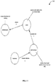
- FIG. 1 illustrates an embodiment of a high level system for raw image acquisition and processing 100 .
- FIG. 2 illustrates an embodiment of an image processing system 200 .
- FIG. 3 an embodiment of a raw image processing system 300 .
- FIG. 4 illustrates an embodiment of an image processor 400 .
- FIG. 5 illustrates additional details 500 of an image processor 400 .
- FIG. 6 illustrates an embodiment of an object identification and refinement sub-system 600 of an image processor 400 .
- FIG. 7 illustrates an embodiment of a raw image processing system 700 .
- FIG. 8 illustrates an embodiment of a system for creating a hybrid raw image 800 .
- FIG. 9 illustrates an embodiment of a system for the aggregation and processing of multiple raw images 900 .
- FIG. 10 illustrates an embodiment of a system for the processing image panoramas 1000 .
- FIG. 11 illustrates an example of a print or display graph 110 .
- FIG. 12 illustrates an embodiment of an object oriented drawing triple 1200 generated for the print or display graph 110 example illustrated in FIG. 11 .
- FIG. 13 illustrates an embodiment of a triple diagram generator 1300 .
- FIG. 14 illustrates a machine system 1400 that may be utilized to implement components of the described image processing systems.
- a computerized drawing tool includes logic and components capture and convert a whiteboard/paper/electronic drawing into object definitions.
- the tool includes logic to recognize annotations on the drawings and to interpret the annotations into specifically identified signals between physical components, including the timing of those signals, and including concurrency if present.
- the tool includes logic to generate a system diagram, an action flow diagram, and at least part of a flow chart based on the identified objects, lines, and annotations in the captured image.
- the tool may further comprise logic to identify transformations as specified by a reference to the component which could be an arrow or a line to the component and a label which the label describes the transformation explicitly or by a code or symbol.
- the system can produce a “triple” set of illustrations: a system diagram showing components and their inter-signaling, an action diagram showing the timing of signals in the system, and a flow chart illustrating cause and effect.
- the system may recognize annotations representing conditions on signals between components, or conditions on transformations carried out within components and caused by signals.
- the system identifies proximity of text to lines that begin and end inside or proximate to shapes.
- the lines are interpreted as signals between components (the shapes).
- the names of the shapes are identified from text enclosed by or partially enclosed by the shapes.
- the signal names are identified from the text proximate to the connecting lines.
- the timing of the signals is identified from numbers proximate to the lines, or to the text proximate to the lines. Concurrent signals have the same number. Transformations (actions carried out in response to received signals by components) are identified, for example, by text proximate to the end of lines that don't end near another component (e.g., “stem” lines) but which do end in or near a component on the other end.
- a method of creating an editable image and editable text from a hand-drawn or other static two-dimensional diagram may include receiving a raw image from an image acquisition device; modifying the raw image to a modified image to reduce noise, normalize raw image data, and reduce pixels; recognizing horizontal, vertical, and diagonal lines in the modified image using a line recognizer; connecting the lines in the modified image to form connected lines using a connector that detects and joins proximally positioned terminal ends of the lines in the modified image; recognizing areas bounded by the connected lines as bounded objects using a bounded object recognizer; and/or identifying and classifying the bounded objects using an object identifier.
- Modifying the raw image may include reducing the pixels by reducing pixel information to a single channel to form a reduced raw image, generating a copy of the raw image and applying a smoothing filter to the copy of the raw image to produce a filtered copy of the raw image, and/or subtracting the filtered copy of the raw image from the reduced raw image to remove a raw image background resulting in pixel sets identifiable as linear segments.
- Modifying the raw image may include determining a starting threshold based on an intensity gradient of the raw image, adjusting the starting threshold to minimize a number of isolated pixels in the raw image, performing a threshold operation to further reduce the pixels, and/or performing dilation/erosion operations to adjust a thickness of identifiable linear segments.
- Recognizing the lines in the modified image using the line recognizer may include scanning the modified image signal and identifying a starting pixel based on a particular pixel value; locating an ending pixel connected to the starting pixel by a linear path of pixels equal to a value of the starting pixel; recognizing the linear path of pixels as a line segment; and/or identifying, locating, and recognizing additional starting pixels. Recognizing the lines in the modified image using the line recognizer may include identifying the ending pixel as a new starting pixel.
- Recognizing areas bounded by the connected lines as the bounded objects through the bounded object recognizer may include identifying a first intersection of two lines within a bounding object as a first vertex, identifying a second intersection of two lines within the bounding object as a second vertex, calculating an average line length for the lines in the modified image based on a distance between the first vertex and the second vertex, and/or identifying lines that do not form the bounding object as strings.
- An editable image and editable text may be generated by transforming a hand-drawn or other static two-dimensional diagram.
- a hand-drawn or other static raw image is captured using a device for recording visual images such as a camera, phone, video recorder, scanner, audio recording device, other such device, or a combination thereof.
- the images may be recordings with the help of an accelerometer, gyroscope, or other means for combining motion data with an alignment algorithm.
- Images may be input from panoramic or standard frame images.
- devices may capture multiple frames of the same object, information from which can be aggregated to produce the best manipulable digital raw image.
- images may be resident on a computer or have been rendered by a computer or computer program.
- the application may zoom in on a particular aspect of a drawing or other raw image for clarification.
- the raw image capturing device may show a preview of a raw image to a user so that the user can adjust the input to capture the most accurate raw image for processing.
- the raw image may be captured by uploading a previously created raw image from persistent storage and processed as described below.
- the captured raw image is then processed to identify each object in the raw image and determine what each object represents.
- the objects are then recreated in digital format and superimposed in a layer over the captured raw image so that the user can correct or edit the objects to represent the desired information or achieve the desired effect.
- the opacity of the recreated raw image may be increased or decreased to make the original raw image more or less visible under the recreated raw image. This allows a user to easily compare the original static raw image to the re-created raw image.
- Object identification and recreation may be accomplished by processing the captured raw image to reduce noise, normalize the raw image data, and reduce pixel information using edge detection algorthims.
- Noise reduction may occur by any means generally used.
- noise reduction occurs by the application of one or more filters such as a Gaussian filter, bilateral filter and/or guided filter. Such filters may be applied alone, or in combination in any order.
- the intensity gradient of the raw image is located using one or more operators including the Sobel operator, Prewitt operator, and Robert Cross Operator. Such operators may be applied alone, or in combination in any order. The application of these operators allows for the isolation of horizontal, vertical and diagonal lines in the captured raw image.
- a search is carried out to determine if the gradient magnitude assumes a local maximum in the gradient direction. Non-Maximum suppression is then applied to remove unwanted pixels and help thin edges. Pixels that belong to an edge are then identified using thresholding hysteresis. Using thresholding hystereisis, two thresholds are determined, high and low. A high threshold is initially applied marking the edges that are more likely to be certain. The Object recognizer ( 904 ) assumes that important edges are along continuous curves, allowing the capturing of faint sections of lines while discarding background pixels that do not constitute a line. Starting from these and using directional information, edges are traced through the raw image and a lower threshold is then applied, allowing faint sections of edges to be added to the re-created raw image.
- the raw image may be further refined using a Hough transform to identify shapes and lines.
- the Hough transform may be further refined using gradient direction to reduce the number of votes in a parameter space using kernel-based Hough transform and Hough transform of curves.
- Shape recognition may be applied by any means generally used.
- the number of continuous lines in a shape may be identified with sharp angle changes signifying a different line allowing shapes to be identified based on the number of lines in each object. For example, three or more lines is identified as a polygon, 1 line is identified as a circle.
- shape identity can be further refined based on the angles and lengths of the lines to determine more specific shapes such as squares, triangles, rectangles, rhombuses, or various triangle types.
- shapes may be identified based on pattern recognition.
- the user may be presented with options for each object according to degrees of certainty of recognition.
- the user can then select the correct identification to be applied to the object, may enter the name of a different object, or may edit the shape of the object to appear as desired.
- the user may choose to output the diagram in such a hybrid format with part of the diagram remaining in the hand drawn or static raw image format.
- Any text within the raw image may be processed using optical character recognition (OCR).
- OCR optical character recognition
- the processing may include a learning mode to improve its recognition of an individual's handwriting and the shapes they generally draw in a diagram.
- the digitally generated reproduction of the static raw image may then be manually edited. Portions of the raw image that could not be identified will be correctable by the end user.
- the manipulable raw image may be superimposed on the captured raw image, allowing the individual manipulating the raw image to compare the original and the reproduced raw image line by line.
- more complex elements may be brought into the raw image in other formats such as as a JPEG, bitmap, TIFF, PNG, or GIFF.
- the digitally generated reproduction may then be saved in persistent storage.
- the finished reproduced raw image may be converted to other useful file formats generally used for displaying information.
- the overall processing may include the following relevant actions:
- the first step is to remove the background. This is done by ‘Prepare the raw image’ by the following steps:
- This step is performed to identify polygon shapes from lines in a raw image signal.
- the raw image is scanned and connected sets of pixels are converted to connected lines. Connected line sets that form closed shapes are identified as polygons and are removed and added to a polygon set, while connected line sets that do not form closed shapes are understood as strings. This is done by ‘Find strings and Polygons’ by the following steps:
- step (i) Continue with step (i) until a dead end is reached such as when no more white or found pixels.
- a parameter is used to determine whether a string is a line or not. This parameter is adjusted using the average polygon size. The assumption is that if the average polygon size is large, lines are large and vice versa. This is done by ‘Adjust the Line Length’ by the following steps:
- each polygon found and see if it is a rectangle, a circle, a triangle, a cloud, or just an n-sided polygon. For each polygon:
- step 2 If it does not have 4 line segments, go to step 2.
- step 3 If it does not have 3 line segments, go to step 3.
- step 4 If the polygon has less than a parameter number of vertexes, go to step 4.
- step 4 If the error of the fits is greater than a parameter or the number of petals is less than a parameter, go to step 4.
- FIG. 1 illustrates an embodiment of a high level system for raw image acquisition and processing 100 .
- the system comprises client device 104 , machine network 108 , and server system 102 .
- the client device 104 receives a raw image signal of a print or display graph 110 from the camera 106 and in response processes the raw image to reduce noise, normalize the raw image data and reduce pixel information.
- the server system 102 receives a processed image from client device 104 and in response operates image processor 112 logic (described later) to transform the processed image into a format in which image lines and other geometric objects are manipulable.
- FIG. 2 illustrates an embodiment of an image processing system 200 .
- the system comprises camera 106 , pixel reducer 204 , background remover 206 , noise reducer 208 , image normalizer 210 , image processor 112 , and client device 104 .
- the camera 106 captures an RGB (or other color format) image of the print or display graph 110 .
- the pixel reducer 204 receives the captured image from the camera 106 and in response converts the image to greyscale and resizes it to pre-set dimensions.
- the background remover 206 receives the modified image from the pixel reducer 204 and in response removes the image background, retaining in the image greyscale lines.
- the noise reducer 208 receives a modified image from the background remover 206 and in response adjusts threshold values to minimize a number of isolated (unconnected) pixel values.
- the noise reducer image normalizer 210 receives a modified image from the noise reducer 208 and in response performs threshold operations to produce a monochrome image.
- the image processor 112 receives a modified image from the image normalizer 210 and in response performs processing to convert the image into a format in which image lines and other geometric objects are manipulable. This final format is communicated to the client device 104 .
- FIG. 3 an embodiment of a raw image processing system 300 .
- the system comprises an object recognizer 302 , an object identifier 308 , and various sensors and transducers (e.g., camera 106 , sensor/transducer (sound) 304 , and sensor/transducer (position) 306 ).
- sensors and transducers e.g., camera 106 , sensor/transducer (sound) 304 , and sensor/transducer (position) 306 ).
- the object recognizer 302 receives a raw image and readings/data from sensors and transducers and in response analyzes the raw image, applying the readings, generating a list of bounding areas that are determined to contain atomic objects to be identified and converted in the raw image.
- the object identifier 308 receives the object bounds formation from the object recognizer 302 and in response analyzes each object and identifies the type and/or content of the object.
- FIG. 4 illustrates an embodiment of an image processor 400 .
- the image processor 400 (e.g., an embodiment of image processor 112 ) comprises a connected line identifier 402 , a line connector 404 , an object recognizer 302 , a polygon identifier 406 , and a string identifier 408 .
- a modified image from the image normalizer 210 is received by the connected line identifier 402 which scans the image for connected sets of pixels that are converted to connected lines.
- the line connector 404 receives lines from the connected line identifier 402 and in response scans for line ends that are proximate to other line ends (within a set radius, for example) and connects them (adds pixels to the image to connect the ends, for example).
- the object recognizer 302 receives connected lines from the line connector 404 and in response generates a list of bounding areas (polygon sets).
- the polygon identifier 406 receives the polygon set from the object recognizer 302 and in response analyzes each polygon object and identifies the type and/or content of the object.
- the string identifier 408 receives the modified image (including connected lines) from the object recognizer 302 and in response refines the set by identifying lines and removing strings determined to be chaff.
- FIG. 5 illustrates additional details 500 of an image processor 400 .
- the image processor 400 comprises object recognizer 302 , line length identifier 504 , line length adjuster 502 , straight string converter 506 , separator 508 , and shape connector 510 .
- the object recognizer 302 provides polygon sets to the line length adjuster 502 and the line length identifier 504 .
- the line length adjuster 502 determines a minimum line length parameter based on an average polygon size.
- the line length identifier 504 receives a processed image from the object recognizer 302 and in response scans through strings and calculates the length of each string.
- the line length identifier 504 receives a line length parameter from the line length adjuster 502 and in response compares the length of each string and compares it to the line length parameter, and moves a string to a chaff set if string is shorter than the parameter and overlays another string.
- the straight string converter 506 receives an image from the line length identifier 504 and in response scans through the strings in the image data and calculates the shortest path between furthest apart vertexes of the strings.
- the straight string converter 506 receives a line length parameter from the line length adjuster 502 and in response compares the shortest path distance to minimum line length parameter if string is a straight line.
- the separator 508 receives a string set from the straight string converter 506 and in response ignores modified strings (straight line, polygon, etc) and compares strings against themselves to determine removal as chaff.
- the shape connector 510 receives a processed image from the separator 508 and in response combines the processed image data comprising modified strings with a processed polygon set to generate a structured drawing.
- FIG. 6 illustrates an embodiment of an object identification and refinement sub-system 600 of an image processor 400 .
- the polygon refiner 602 receives a polygon set signal from the object recognizer 302 and in response analyzes each polygon for similarity to a basic shape from a triangle, quadrilateral, or pentagon set, forming a refined polygon set.
- the polygon identifier 406 receives a refined polygon set from the polygon refiner 602 and in response examines each polygon in the set for more specific shape typing to a rectangle, a circle, a triangle, a cloud, or just an n-sided polygon.
- the shape connector 510 receives a processed polygon set from the polygon identifier 406 and in response identifies lines that connect polygons, and tags them with numbers, generating a manipulable image.
- the 410 also receives a processed image from the string identifier 408 and in response applies the refined polygon set to find lines that connect polygons, and to tag them with numbers and generating a manipulable image.
- FIG. 7 illustrates an embodiment of a raw image processing system 700 .
- the raw image processing system 700 converts a print or display graph 110 including geometric object representations into a format in which the geometric objects are parameterized (converted to structured metadata defining the geometry of the objects) in a structured machine data graph.
- the raw image processing system 700 comprises camera 106 , image processor 112 , persistent machine storage 702 , persistent machine storage 704 , location sensor 706 , preview application 708 , object-oriented drawing editor 710 , format converter 712 , and digital file 716 .
- the image processor 112 receives an image from the camera 106 and positional data from the location sensor 706 and in response cross-references the positional data with the raw image to generate structured drawing data.
- the raw image may be provided to the image processor 112 from persistent machine storage 702 .
- the preview application 708 receives the structured drawing data from the image processor 112 and in response presents it to the user 714 for preview, allowing the user to continue capturing raw image data in an attempt to obtain more accurate structured data, or accepting the preview and continuing.
- the object-oriented drawing editor 710 receives structured drawing data from preview application 708 and in response displays it to the user along with editing tools to change the structured drawing data (move objects, connect objects, resize objects, etc.).
- the user 714 may operate the object-oriented drawing editor 710 to save the modified data to digital file 716 on the persistent machine storage 704 for later use, potentially converting the structured drawing data to a different file format in the process by engaging the format converter 712 .
- FIG. 8 illustrates an embodiment of a system for creating a hybrid raw image 800 .
- the system for creating a hybrid raw image 800 comprises camera 106 , image processor 112 , user input device 802 , and object-oriented drawing editor 710 .
- the image processor 112 receives a raw image from the camera 106 and in response processes the raw image into a manipulable raw image.
- the object-oriented drawing editor 710 receives a processed (manipulable) raw image signal from the image processor 112 and in response accepts inputs to produce overlay data and manipulations in the raw image.
- the object-oriented drawing editor 710 receives overlay data from the user input device 802 and in response applies the overlay data (which can include movement, re-sizing, deletions, additions, etc.) to the raw image to produce a compound (hybrid) raw image object in machine memory.
- FIG. 9 illustrates an embodiment of a system for the aggregation and processing of multiple raw images 900 .
- the system for the aggregation and processing of multiple raw images 900 comprises camera 106 , aggregator 902 , and image processor 112 .
- the system utilizes multiple images, from possibly multiple vantage points/perspectives, to identify objects and interconnections among objects in a print or display graph 110 .
- the aggregator 902 receives and combines multiple raw images and transforms them into an aggregate raw image (using known image combination techniques to enhance resolution and image quality).
- the image processor 112 receives the aggregated raw image from the aggregator 902 and in response processes the aggregate raw image in the manners already described for a single raw image.
- FIG. 9 illustrates an embodiment of a system for the processing image panoramas 1000 .
- the system for the processing image panoramas 1000 comprises a camera 106 , panorama renderer 1002 , image processor 112 , and user input device 802 .
- the system utilizes a panorama, representing multiple images from multiple vantage points/perspectives stitched together into a single image, to identify objects and interconnections among objects in a print or display graph 110 .
- the panorama renderer 1002 receives an image panorama and renders it for a user to select the best portion(s) to convert into a manipulable set of drawing objects.
- the image processor 112 receives the aggregated raw image from the panorama renderer 1002 and in response processes the selected raw image portion(s) in the manners already described for a single raw image.
- FIG. 11 illustrates an example of a print or display graph 110 .
- the print or display graph 110 may for example be a whiteboard or paper sketch which may be processed into a ‘triple’ set of computerized illustrations (system diagram, action flow diagram, and flow chart).
- the sketch includes shapes (e.g., circles) representing components in a machine system. There are lines between the shapes, annotated with text and numbers. There are lead lines with proximate text terminating within the shapes, representing processing/transformations by the components.
- FIG. 12 illustrates an embodiment of an object oriented drawing triple 1200 generated for the print or display graph 110 example illustrated in FIG. 11 .
- the image processing system 200 is operated to identify shape objects in the print or display graph 110 and communication lines (e.g., arrows) between the shape objects.
- Text strings associated in the print or display graph 110 with the shape objects are identified, and graphic stencils having a configured correspondence with the shape objects are selected to represent the corresponding shape objects.
- the text strings in the print or display graph 110 are then made labels to the stencils, and connector objects (e.g., arrow connector objects) are inserted between the stencils corresponding to the identified communication lines in the print or display graph 110 .
- the result is a connected system (i.e., block) diagram as illustrated for example by system block diagram 1204 .
- Stem lines e.g., lines having a floating endpoint proximate with text, and a second endpoint terminating on, in, or near a shape object
- flow chart 1206 The top to bottom order for the actions in the flow chart is determined by identifying a sequence number proximate with or otherwise associable with the communication lines in the print or display graph 110 .
- a data flow diagram may also be generated from the print or display graph 110 .
- Vertical lines in the data flow diagram are labeled with the stencil (shape object) labels, and horizontal (communication) lines are labeled with labels identified as associated with communication lines in the print or display graph 110 .
- the system may auto-generate text to associate with the object oriented drawing triple 1200 , by traversing the generated data flow diagram 1202 , flow chart 1206 , and system block diagram 1204 .
- the traverse text combines the actors (shape labels), actions (stem line labels), and communications (communication line labels) forming the system into a natural language set of one or more sentences.
- the sentences are ordered according to the sequence numbers associated with the communication lines.
- An example of auto-generated traverse text that would be generated and associated with the object oriented drawing triple 1200 is: “The system comprises a television, a first mobile device, a server, and a second mobile device.
- the first mobile device receives a channel selection signal from the television and in response matches the channel selection to an entry in an EPG.
- the server receives a content title signal from the first mobile device and in response correlates the content title to a stream file(s).
- the second mobile device receives a stream signal from the server and in response renders the stream for viewing.”
- FIG. 13 illustrates an embodiment of a triple diagram generator 1300 .
- the triple diagram generator 1300 comprises image processor 112 , stencilizer 1302 , block diagrammer 1308 , line characterizer 1304 , flow charter 1310 , label characterizer 1306 , data flow diagrammer 1312 , digital file 1314 , and traverser 1306 .
- the image processor 112 outputs a set of drawing objects (lines, text strings, and shapes for example) generated by transforming a print or display graph 110 . All or subsets of the drawing objects are received by the stencilizer 1302 (which is optional in the triple diagram generator 1300 ), the line characterizer 1304 , and the label characterizer 1306 .
- the stencilizer 1302 accesses a database (e.g., database 1414 ) to locate stencils corresponding to drawing objects.
- a database e.g., database 1414
- the correspondence between stencils and drawing objects may be based upon text strings that the system identifies as being labels for the drawing objects.
- the stencilizer 1302 may also act upon an output of the label characterizer 1306 .
- the line characterizer 1304 analyzes lines that are not part of shapes in the drawing for characteristics indicative of a line type (communication lines, stem lines for example). Lines are tagged (associated with) their characteristic type and other attributes, such as source and destination objects for communication lines, shape object being labeled for object labels, and shape object actor for action stem lines.
- the label characterizer 1306 analyzes the text strings in the drawing for characteristics indicative of label types (sequence numbers, object labels, communication line labels, actions for example) and tags the text strings with their characteristic type and possible other attributes (e.g., associated communication line, stem line, or shape object).
- Tagged labels and tagged lines are input to the data flow diagrammer 1312 , along with drawing objects, and are transformed into the data flow diagram 1202 . Those skilled in the art will appreciate how this may be done in a number of ways once the drawing labels and lines are identified and characterized as described herein.
- Tagged labels and tagged lines are input to the flow charter 1310 , along with drawing objects, and are transformed into the flow chart 1206 . Those skilled in the art will appreciate how this may be done in a number of ways once the drawing labels and lines are identified and characterized as described herein.
- Tagged labels, stencils, and lines are input to the block diagrammer 1308 , along with drawing objects, and are transformed into the system block diagram 1204 .
- the stencilizer 1302 may not be utilized in all embodiments, in which case the shapes from the transformed raw image will be used instead in the system block diagram 1204 .
- FIG. 14 illustrates a machine system 1400 that may be utilized to implement components of the described image processing systems.
- the machine system may implement all or portions of the image processor 112 .
- machine system 1400 may include a desktop PC, server, workstation, mobile phone, laptop, tablet, set-top box, appliance, or other computing device that is capable of performing operations such as those described herein.
- machine system 1400 may include many more components than those shown in FIG. 2 . However, it is not necessary that all of these generally conventional components be shown in order to disclose an illustrative embodiment.
- Collectively, the various tangible components or a subset of the tangible components may be referred to herein as “logic” configured or adapted in a particular way, for example as logic configured or adapted with particular software or firmware.
- machine system 1400 may comprise one or more physical and/or logical devices that collectively provide the functionalities described herein. In some embodiments, machine system 1400 may comprise one or more replicated and/or distributed physical or logical devices.
- machine system 1400 may comprise one or more computing resources provisioned from a “cloud computing” provider, for example, Amazon Elastic Compute Cloud (“Amazon EC2”), provided by Amazon.com, Inc. of Seattle, Wash.; Sun Cloud Compute Utility, provided by Sun Microsystems, Inc. of Santa Clara, Calif.; Windows Azure, provided by Microsoft Corporation of Redmond, Wash., and the like.
- Amazon Elastic Compute Cloud (“Amazon EC2”)
- Sun Cloud Compute Utility provided by Sun Microsystems, Inc. of Santa Clara, Calif.
- Windows Azure provided by Microsoft Corporation of Redmond, Wash., and the like.
- Machine system 1400 includes a bus 1402 interconnecting several components including a network interface 1408 , a display 1406 , a central processing unit 1410 , and a memory 1404 .
- Memory 1404 generally comprises a random access memory (“RAM”) and permanent non-transitory mass storage device, such as a hard disk drive or solid-state drive. Memory 1404 stores an operating system 1412 .
- RAM random access memory
- Permanent non-transitory mass storage device such as a hard disk drive or solid-state drive.
- Memory 1404 stores an operating system 1412 .
- ⁇ 1404 of machine system 1400 may be loaded into memory 1404 of machine system 1400 using a drive mechanism (not shown) associated with a non-transitory computer-readable medium 1416 , such as a floppy disc, tape, DVD/CD-ROM drive, memory card, or the like.
- a drive mechanism (not shown) associated with a non-transitory computer-readable medium 1416 , such as a floppy disc, tape, DVD/CD-ROM drive, memory card, or the like.
- Memory 1404 also includes database 1414 .
- server 200 may communicate with database 1414 via network interface 1408 , a storage area network (“SAN”), a high-speed serial bus, and/or via the other suitable communication technology.
- SAN storage area network
- database 1414 may comprise one or more storage resources provisioned from a “cloud storage” provider, for example, Amazon Simple Storage Service (“Amazon S 3 ”), provided by Amazon.com, Inc. of Seattle, Wash., Google Cloud Storage, provided by Google, Inc. of Mountain View, Calif., and the like.
- Amazon S 3 Amazon Simple Storage Service
- Google Cloud Storage provided by Google, Inc. of Mountain View, Calif., and the like.
- references to “one embodiment” or “an embodiment” do not necessarily refer to the same embodiment, although they may.
- the words “comprise,” “comprising,” and the like are to be construed in an inclusive sense as opposed to an exclusive or exhaustive sense; that is to say, in the sense of “including, but not limited to.” Words using the singular or plural number also include the plural or singular number respectively, unless expressly limited to a single one or multiple ones.
- the words “herein,” “above,” “below” and words of similar import when used in this application, refer to this application as a whole and not to any particular portions of this application.
- Logic refers to machine memory circuits, non transitory machine readable media, and/or circuitry which by way of its material and/or material-energy configuration comprises control and/or procedural signals, and/or settings and values (such as resistance, impedance, capacitance, inductance, current/voltage ratings, etc.), that may be applied to influence the operation of a device.
- Magnetic media, electronic circuits, electrical and optical memory (both volatile and nonvolatile), and firmware are examples of logic.
- Logic specifically excludes pure signals or software per se (however does not exclude machine memories comprising software and thereby forming configurations of matter).
- logic may be distributed throughout one or more devices, and/or may be comprised of combinations memory, media, processing circuits and controllers, other circuits, and so on. Therefore, in the interest of clarity and correctness logic may not always be distinctly illustrated in drawings of devices and systems, although it is inherently present therein.
- the implementer may opt for a hardware and/or firmware vehicle; alternatively, if flexibility is paramount, the implementer may opt for a solely software implementation; or, yet again alternatively, the implementer may opt for some combination of hardware, software, and/or firmware.
- any vehicle to be utilized is a choice dependent upon the context in which the vehicle will be deployed and the specific concerns (e.g., speed, flexibility, or predictability) of the implementer, any of which may vary.
- optical aspects of implementations may involve optically-oriented hardware, software, and or firmware.
- a signal bearing media include, but are not limited to, the following: recordable type media such as floppy disks, hard disk drives, CD ROMs, digital tape, flash drives, SD cards, solid state fixed or removable storage, and computer memory.
- circuitry includes, but is not limited to, electrical circuitry having at least one discrete electrical circuit, electrical circuitry having at least one integrated circuit, electrical circuitry having at least one application specific integrated circuit, circuitry forming a general purpose computing device configured by a computer program (e.g., a general purpose computer configured by a computer program which at least partially carries out processes and/or devices described herein, or a microprocessor configured by a computer program which at least partially carries out processes and/or devices described herein), circuitry forming a memory device (e.g., forms of random access memory), and/or circuitry forming a communications device (e.g., a modem, communications switch, or optical-electrical equipment).
- a computer program e.g., a general purpose computer configured by a computer program which at least partially carries out processes and/or devices described herein, or a microprocessor configured by a computer program which at least partially carries out processes and/or devices described herein
- circuitry forming a memory device e.g.
Landscapes
- Engineering & Computer Science (AREA)
- Physics & Mathematics (AREA)
- General Physics & Mathematics (AREA)
- Theoretical Computer Science (AREA)
- Multimedia (AREA)
- Computer Vision & Pattern Recognition (AREA)
- Artificial Intelligence (AREA)
- Image Processing (AREA)
Abstract
Description
Claims (4)
Priority Applications (2)
| Application Number | Priority Date | Filing Date | Title |
|---|---|---|---|
| US16/170,563 US10909358B2 (en) | 2015-06-04 | 2018-10-25 | System and method for capturing and interpreting images into triple diagrams |
| US17/147,332 US11625871B2 (en) | 2015-06-04 | 2021-01-12 | System and method for capturing and interpreting images into triple diagrams |
Applications Claiming Priority (2)
| Application Number | Priority Date | Filing Date | Title |
|---|---|---|---|
| US14/731,225 US20180101724A1 (en) | 2015-06-04 | 2015-06-04 | System and method for capturing and interpreting images into triple diagrams |
| US16/170,563 US10909358B2 (en) | 2015-06-04 | 2018-10-25 | System and method for capturing and interpreting images into triple diagrams |
Related Parent Applications (1)
| Application Number | Title | Priority Date | Filing Date |
|---|---|---|---|
| US14/731,225 Continuation US20180101724A1 (en) | 2015-06-04 | 2015-06-04 | System and method for capturing and interpreting images into triple diagrams |
Related Child Applications (1)
| Application Number | Title | Priority Date | Filing Date |
|---|---|---|---|
| US17/147,332 Continuation US11625871B2 (en) | 2015-06-04 | 2021-01-12 | System and method for capturing and interpreting images into triple diagrams |
Publications (2)
| Publication Number | Publication Date |
|---|---|
| US20190102615A1 US20190102615A1 (en) | 2019-04-04 |
| US10909358B2 true US10909358B2 (en) | 2021-02-02 |
Family
ID=61829691
Family Applications (3)
| Application Number | Title | Priority Date | Filing Date |
|---|---|---|---|
| US14/731,225 Abandoned US20180101724A1 (en) | 2015-06-04 | 2015-06-04 | System and method for capturing and interpreting images into triple diagrams |
| US16/170,563 Active 2035-09-06 US10909358B2 (en) | 2015-06-04 | 2018-10-25 | System and method for capturing and interpreting images into triple diagrams |
| US17/147,332 Active 2035-11-01 US11625871B2 (en) | 2015-06-04 | 2021-01-12 | System and method for capturing and interpreting images into triple diagrams |
Family Applications Before (1)
| Application Number | Title | Priority Date | Filing Date |
|---|---|---|---|
| US14/731,225 Abandoned US20180101724A1 (en) | 2015-06-04 | 2015-06-04 | System and method for capturing and interpreting images into triple diagrams |
Family Applications After (1)
| Application Number | Title | Priority Date | Filing Date |
|---|---|---|---|
| US17/147,332 Active 2035-11-01 US11625871B2 (en) | 2015-06-04 | 2021-01-12 | System and method for capturing and interpreting images into triple diagrams |
Country Status (1)
| Country | Link |
|---|---|
| US (3) | US20180101724A1 (en) |
Cited By (1)
| Publication number | Priority date | Publication date | Assignee | Title |
|---|---|---|---|---|
| US11574084B1 (en) * | 2022-01-31 | 2023-02-07 | Protolabs, Inc. | Methods and systems for geometric analysis of a part for manufacture |
Families Citing this family (7)
| Publication number | Priority date | Publication date | Assignee | Title |
|---|---|---|---|---|
| US20180101724A1 (en) * | 2015-06-04 | 2018-04-12 | Mowdo | System and method for capturing and interpreting images into triple diagrams |
| US10339690B2 (en) * | 2015-12-18 | 2019-07-02 | Ricoh Co., Ltd. | Image recognition scoring visualization |
| US11023526B2 (en) * | 2017-06-02 | 2021-06-01 | International Business Machines Corporation | System and method for graph search enhancement |
| US11182133B2 (en) | 2019-07-17 | 2021-11-23 | Red Hat, Inc. | Conversion of images into CI/CD jobs |
| US11151372B2 (en) | 2019-10-09 | 2021-10-19 | Elsevier, Inc. | Systems, methods and computer program products for automatically extracting information from a flowchart image |
| CN111931754B (en) * | 2020-10-14 | 2021-01-15 | 深圳市瑞图生物技术有限公司 | Method and system for identifying target object in sample and readable storage medium |
| US12119989B2 (en) * | 2021-10-29 | 2024-10-15 | Keysight Technologies, Inc. | System and method for configuring network elements in a design network topology |
Citations (11)
| Publication number | Priority date | Publication date | Assignee | Title |
|---|---|---|---|---|
| US5729637A (en) | 1994-08-31 | 1998-03-17 | Adobe Systems, Inc. | Method and apparatus for producing a hybrid data structure for displaying a raster image |
| US6081620A (en) * | 1997-02-11 | 2000-06-27 | Silicon Biology, Inc. | System and method for pattern recognition |
| US6415097B1 (en) | 1992-03-11 | 2002-07-02 | Canon Kabushiki Kaisha | Image reproducing and storage arrangement with stored image index information |
| US7136082B2 (en) * | 2002-01-25 | 2006-11-14 | Xerox Corporation | Method and apparatus to convert digital ink images for use in a structured text/graphics editor |
| US7139004B2 (en) * | 2002-01-25 | 2006-11-21 | Xerox Corporation | Method and apparatus to convert bitmapped images for use in a structured text/graphics editor |
| US20080137958A1 (en) * | 2006-12-06 | 2008-06-12 | Industrial Technology Research Institute | Method of utilizing mobile communication device to convert image character into text and system thereof |
| US20080182620A1 (en) | 2006-12-28 | 2008-07-31 | Edner Lors | Hand held mobile communication device and method for managing printed documents |
| US20100153150A1 (en) * | 2008-12-12 | 2010-06-17 | Sap Ag | Software for business adaptation catalog modeling |
| US20120039503A1 (en) * | 2010-08-12 | 2012-02-16 | Honeywell International Inc. | System and method for constructing a three dimensional operational graphic from a two dimensional building control subsystem drawing |
| US20180101724A1 (en) * | 2015-06-04 | 2018-04-12 | Mowdo | System and method for capturing and interpreting images into triple diagrams |
| US10049476B1 (en) * | 2015-05-15 | 2018-08-14 | Turbopatent,Corp. | System and method of creating an editable text and images from a captured image of a hand-drawn and/or static two-dimensional diagram |
Family Cites Families (18)
| Publication number | Priority date | Publication date | Assignee | Title |
|---|---|---|---|---|
| US5517578A (en) * | 1993-05-20 | 1996-05-14 | Aha! Software Corporation | Method and apparatus for grouping and manipulating electronic representations of handwriting, printing and drawings |
| TW367447B (en) * | 1994-12-21 | 1999-08-21 | Canon Kk | Block selection review and editing system |
| US6233353B1 (en) * | 1998-06-29 | 2001-05-15 | Xerox Corporation | System for segmenting line drawings from text within a binary digital image |
| US6411733B1 (en) * | 1998-11-25 | 2002-06-25 | Xerox Corporation | Method and apparatus for separating document image object types |
| CA2470930A1 (en) * | 2003-08-21 | 2005-02-21 | Microsoft Corporation | Electronic ink processing |
| EP1665128A4 (en) * | 2003-08-21 | 2007-10-17 | Microsoft Corp | ELECTRONIC INK PROCESSING |
| CN1662877B (en) * | 2003-08-21 | 2010-05-12 | 微软公司 | Method for analyzing electronic ink |
| US7729538B2 (en) * | 2004-08-26 | 2010-06-01 | Microsoft Corporation | Spatial recognition and grouping of text and graphics |
| US7904810B2 (en) * | 2004-09-21 | 2011-03-08 | Microsoft Corporation | System and method for editing a hand-drawn list in ink input |
| US7394935B2 (en) * | 2004-09-21 | 2008-07-01 | Microsoft Corporation | System and method for editing a hand-drawn chart in ink input |
| US7412094B2 (en) * | 2004-09-21 | 2008-08-12 | Microsoft Corporation | System and method for editing a hand-drawn table in ink input |
| US7503015B2 (en) * | 2004-09-21 | 2009-03-10 | Microsoft Corporation | System and method for editing ink objects |
| US7800613B2 (en) * | 2004-12-02 | 2010-09-21 | Tableau Software, Inc. | Computer systems and methods for visualizing data with generation of marks |
| US8099674B2 (en) * | 2005-09-09 | 2012-01-17 | Tableau Software Llc | Computer systems and methods for automatically viewing multidimensional databases |
| US8014607B2 (en) * | 2007-03-23 | 2011-09-06 | Palo Alto Research Center Incorporated | Method and apparatus for creating and editing node-link diagrams in pen computing systems |
| US7907141B2 (en) * | 2007-03-23 | 2011-03-15 | Palo Alto Research Center Incorporated | Methods and processes for recognition of electronic ink strokes |
| US7725493B2 (en) * | 2007-03-23 | 2010-05-25 | Palo Alto Research Center Incorporated | Optimization method and process using tree searching operation and non-overlapping support constraint requirements |
| US20120213429A1 (en) * | 2011-02-17 | 2012-08-23 | Infosys Technologies Limited | System and method for extracting flowchart information from digital images |
-
2015
- 2015-06-04 US US14/731,225 patent/US20180101724A1/en not_active Abandoned
-
2018
- 2018-10-25 US US16/170,563 patent/US10909358B2/en active Active
-
2021
- 2021-01-12 US US17/147,332 patent/US11625871B2/en active Active
Patent Citations (15)
| Publication number | Priority date | Publication date | Assignee | Title |
|---|---|---|---|---|
| US6415097B1 (en) | 1992-03-11 | 2002-07-02 | Canon Kabushiki Kaisha | Image reproducing and storage arrangement with stored image index information |
| US5729637A (en) | 1994-08-31 | 1998-03-17 | Adobe Systems, Inc. | Method and apparatus for producing a hybrid data structure for displaying a raster image |
| US6385350B1 (en) | 1994-08-31 | 2002-05-07 | Adobe Systems Incorporated | Method and apparatus for producing a hybrid data structure for displaying a raster image |
| US6081620A (en) * | 1997-02-11 | 2000-06-27 | Silicon Biology, Inc. | System and method for pattern recognition |
| US20070065013A1 (en) * | 2002-01-25 | 2007-03-22 | Xerox Corporation | Method and apparatus to convert digital ink images for use in a structured text/graphics editor |
| US7139004B2 (en) * | 2002-01-25 | 2006-11-21 | Xerox Corporation | Method and apparatus to convert bitmapped images for use in a structured text/graphics editor |
| US7136082B2 (en) * | 2002-01-25 | 2006-11-14 | Xerox Corporation | Method and apparatus to convert digital ink images for use in a structured text/graphics editor |
| US20080137958A1 (en) * | 2006-12-06 | 2008-06-12 | Industrial Technology Research Institute | Method of utilizing mobile communication device to convert image character into text and system thereof |
| US20080182620A1 (en) | 2006-12-28 | 2008-07-31 | Edner Lors | Hand held mobile communication device and method for managing printed documents |
| US7953441B2 (en) | 2006-12-28 | 2011-05-31 | Edner Lors | Hand held mobile communication device and method for managing printed documents |
| US20100153150A1 (en) * | 2008-12-12 | 2010-06-17 | Sap Ag | Software for business adaptation catalog modeling |
| US20120039503A1 (en) * | 2010-08-12 | 2012-02-16 | Honeywell International Inc. | System and method for constructing a three dimensional operational graphic from a two dimensional building control subsystem drawing |
| US8406477B2 (en) * | 2010-08-12 | 2013-03-26 | Honeywell International Inc. | System and method for constructing a three dimensional operational graphic from a two dimensional building control subsystem drawing |
| US10049476B1 (en) * | 2015-05-15 | 2018-08-14 | Turbopatent,Corp. | System and method of creating an editable text and images from a captured image of a hand-drawn and/or static two-dimensional diagram |
| US20180101724A1 (en) * | 2015-06-04 | 2018-04-12 | Mowdo | System and method for capturing and interpreting images into triple diagrams |
Non-Patent Citations (2)
| Title |
|---|
| Cruz et al., "A sketch on sketch-based interfaces and modeling." In 2010 23rd SIBGRAPI-Conference on Graphics, Patterns and Images Tutorials, pp. 22-33. IEEE, 2010. (Year: 2010). * |
| Shin et al., "Magic canvas: Interactive design of a 3d scene prototype from freehand sketches." Graphics Interface, 2007. (Year: 2007). * |
Cited By (1)
| Publication number | Priority date | Publication date | Assignee | Title |
|---|---|---|---|---|
| US11574084B1 (en) * | 2022-01-31 | 2023-02-07 | Protolabs, Inc. | Methods and systems for geometric analysis of a part for manufacture |
Also Published As
| Publication number | Publication date |
|---|---|
| US20190102615A1 (en) | 2019-04-04 |
| US11625871B2 (en) | 2023-04-11 |
| US20180101724A1 (en) | 2018-04-12 |
| US20210133437A1 (en) | 2021-05-06 |
Similar Documents
| Publication | Publication Date | Title |
|---|---|---|
| US11625871B2 (en) | System and method for capturing and interpreting images into triple diagrams | |
| CN109933756B (en) | Image conversion method, device, device and readable storage medium based on OCR | |
| Liang et al. | Camera-based analysis of text and documents: a survey | |
| US8000529B2 (en) | System and method for creating an editable template from a document image | |
| CN106156761B (en) | Image table detection and identification method for mobile terminal shooting | |
| US8634644B2 (en) | System and method for identifying pictures in documents | |
| US9805281B2 (en) | Model-based dewarping method and apparatus | |
| JP2940936B2 (en) | Tablespace identification method | |
| JP2003515230A (en) | Method and system for separating categorizable symbols of video stream | |
| US10455163B2 (en) | Image processing apparatus that generates a combined image, control method, and storage medium | |
| WO2022089170A1 (en) | Caption area identification method and apparatus, and device and storage medium | |
| CN110472539B (en) | Text detection method and device and computer storage medium | |
| CN112825141B (en) | Method and device for recognizing text, recognition equipment and storage medium | |
| CN111553923B (en) | Image processing method, electronic equipment and computer readable storage medium | |
| CN106846339A (en) | Image detection method and device | |
| CN113436222A (en) | Image processing method, image processing apparatus, electronic device, and storage medium | |
| CN116703797A (en) | Image fusion method, image fusion system, computer equipment and storage medium | |
| US10049476B1 (en) | System and method of creating an editable text and images from a captured image of a hand-drawn and/or static two-dimensional diagram | |
| CN115063818B (en) | Method and system for judging office document font types | |
| CN110991440A (en) | A pixel-driven mobile phone operation interface text detection method | |
| CN113780293A (en) | Interface text recognition method | |
| Dave et al. | OCR text detector and audio convertor | |
| CN105930813B (en) | A method of detection composes a piece of writing this under any natural scene | |
| CN116386064A (en) | Image text detection method, device, equipment and readable storage medium | |
| Ghorpade et al. | Extracting text from video |
Legal Events
| Date | Code | Title | Description |
|---|---|---|---|
| FEPP | Fee payment procedure |
Free format text: ENTITY STATUS SET TO UNDISCOUNTED (ORIGINAL EVENT CODE: BIG.); ENTITY STATUS OF PATENT OWNER: SMALL ENTITY |
|
| FEPP | Fee payment procedure |
Free format text: ENTITY STATUS SET TO SMALL (ORIGINAL EVENT CODE: SMAL); ENTITY STATUS OF PATENT OWNER: SMALL ENTITY |
|
| STPP | Information on status: patent application and granting procedure in general |
Free format text: DOCKETED NEW CASE - READY FOR EXAMINATION |
|
| AS | Assignment |
Owner name: TURBOPATENT INC., WASHINGTON Free format text: ASSIGNMENT OF ASSIGNORS INTEREST;ASSIGNOR:MIRHO, CHARLES A.;REEL/FRAME:048134/0142 Effective date: 20180205 |
|
| STPP | Information on status: patent application and granting procedure in general |
Free format text: NON FINAL ACTION MAILED |
|
| STPP | Information on status: patent application and granting procedure in general |
Free format text: RESPONSE TO NON-FINAL OFFICE ACTION ENTERED AND FORWARDED TO EXAMINER |
|
| STPP | Information on status: patent application and granting procedure in general |
Free format text: PUBLICATIONS -- ISSUE FEE PAYMENT VERIFIED |
|
| STCF | Information on status: patent grant |
Free format text: PATENTED CASE |
|
| AS | Assignment |
Owner name: ROWAN TELS CORP., WASHINGTON Free format text: ASSIGNMENT OF ASSIGNORS INTEREST;ASSIGNOR:TURBOPATENT INC.;REEL/FRAME:059865/0699 Effective date: 20220506 |
|
| MAFP | Maintenance fee payment |
Free format text: PAYMENT OF MAINTENANCE FEE, 4TH YR, SMALL ENTITY (ORIGINAL EVENT CODE: M2551); ENTITY STATUS OF PATENT OWNER: SMALL ENTITY Year of fee payment: 4 |
|
| AS | Assignment |
Owner name: WILMINGTON TRUST, NATIONAL ASSOCIATION AS COLLATERAL AGENT, MINNESOTA Free format text: PATENT SECURITY AGREEMENT (2019 INDENTURE);ASSIGNOR:ROWAN TELS CORP.;REEL/FRAME:068892/0761 Effective date: 20240913 Owner name: WILMINGTON TRUST, NATIONAL ASSOCIATION AS COLLATERAL AGENT, MINNESOTA Free format text: PATENT SECURITY AGREEMENT (2021 INDENTURE);ASSIGNOR:ROWAN TELS CORP.;REEL/FRAME:068892/0689 Effective date: 20240913 Owner name: BANK OF AMERICA, N.A. AS COLLATERAL AGENT, NORTH CAROLINA Free format text: PATENT SECURITY AGREEMENT (CA);ASSIGNOR:ROWAN TELS CORP.;REEL/FRAME:068892/0481 Effective date: 20240913 |