US10906385B2 - Hybrid vehicle powertrains with flywheel energy storage systems - Google Patents
Hybrid vehicle powertrains with flywheel energy storage systems Download PDFInfo
- Publication number
- US10906385B2 US10906385B2 US16/227,082 US201816227082A US10906385B2 US 10906385 B2 US10906385 B2 US 10906385B2 US 201816227082 A US201816227082 A US 201816227082A US 10906385 B2 US10906385 B2 US 10906385B2
- Authority
- US
- United States
- Prior art keywords
- sess
- ice
- cvt
- flywheel
- coupled
- Prior art date
- Legal status (The legal status is an assumption and is not a legal conclusion. Google has not performed a legal analysis and makes no representation as to the accuracy of the status listed.)
- Active, expires
Links
Images


Classifications
-
- B—PERFORMING OPERATIONS; TRANSPORTING
- B60—VEHICLES IN GENERAL
- B60K—ARRANGEMENT OR MOUNTING OF PROPULSION UNITS OR OF TRANSMISSIONS IN VEHICLES; ARRANGEMENT OR MOUNTING OF PLURAL DIVERSE PRIME-MOVERS IN VEHICLES; AUXILIARY DRIVES FOR VEHICLES; INSTRUMENTATION OR DASHBOARDS FOR VEHICLES; ARRANGEMENTS IN CONNECTION WITH COOLING, AIR INTAKE, GAS EXHAUST OR FUEL SUPPLY OF PROPULSION UNITS IN VEHICLES
- B60K6/00—Arrangement or mounting of plural diverse prime-movers for mutual or common propulsion, e.g. hybrid propulsion systems comprising electric motors and internal combustion engines
- B60K6/08—Prime-movers comprising combustion engines and mechanical or fluid energy storing means
- B60K6/10—Prime-movers comprising combustion engines and mechanical or fluid energy storing means by means of a chargeable mechanical accumulator, e.g. flywheel
- B60K6/105—Prime-movers comprising combustion engines and mechanical or fluid energy storing means by means of a chargeable mechanical accumulator, e.g. flywheel the accumulator being a flywheel
-
- B—PERFORMING OPERATIONS; TRANSPORTING
- B60—VEHICLES IN GENERAL
- B60K—ARRANGEMENT OR MOUNTING OF PROPULSION UNITS OR OF TRANSMISSIONS IN VEHICLES; ARRANGEMENT OR MOUNTING OF PLURAL DIVERSE PRIME-MOVERS IN VEHICLES; AUXILIARY DRIVES FOR VEHICLES; INSTRUMENTATION OR DASHBOARDS FOR VEHICLES; ARRANGEMENTS IN CONNECTION WITH COOLING, AIR INTAKE, GAS EXHAUST OR FUEL SUPPLY OF PROPULSION UNITS IN VEHICLES
- B60K6/00—Arrangement or mounting of plural diverse prime-movers for mutual or common propulsion, e.g. hybrid propulsion systems comprising electric motors and internal combustion engines
- B60K6/20—Arrangement or mounting of plural diverse prime-movers for mutual or common propulsion, e.g. hybrid propulsion systems comprising electric motors and internal combustion engines the prime-movers consisting of electric motors and internal combustion engines, e.g. HEVs
- B60K6/22—Arrangement or mounting of plural diverse prime-movers for mutual or common propulsion, e.g. hybrid propulsion systems comprising electric motors and internal combustion engines the prime-movers consisting of electric motors and internal combustion engines, e.g. HEVs characterised by apparatus, components or means specially adapted for HEVs
- B60K6/30—Arrangement or mounting of plural diverse prime-movers for mutual or common propulsion, e.g. hybrid propulsion systems comprising electric motors and internal combustion engines the prime-movers consisting of electric motors and internal combustion engines, e.g. HEVs characterised by apparatus, components or means specially adapted for HEVs characterised by chargeable mechanical accumulators, e.g. flywheels
-
- B—PERFORMING OPERATIONS; TRANSPORTING
- B60—VEHICLES IN GENERAL
- B60K—ARRANGEMENT OR MOUNTING OF PROPULSION UNITS OR OF TRANSMISSIONS IN VEHICLES; ARRANGEMENT OR MOUNTING OF PLURAL DIVERSE PRIME-MOVERS IN VEHICLES; AUXILIARY DRIVES FOR VEHICLES; INSTRUMENTATION OR DASHBOARDS FOR VEHICLES; ARRANGEMENTS IN CONNECTION WITH COOLING, AIR INTAKE, GAS EXHAUST OR FUEL SUPPLY OF PROPULSION UNITS IN VEHICLES
- B60K17/00—Arrangement or mounting of transmissions in vehicles
- B60K17/22—Arrangement or mounting of transmissions in vehicles characterised by arrangement, location, or type of main drive shafting, e.g. cardan shaft
-
- B—PERFORMING OPERATIONS; TRANSPORTING
- B60—VEHICLES IN GENERAL
- B60K—ARRANGEMENT OR MOUNTING OF PROPULSION UNITS OR OF TRANSMISSIONS IN VEHICLES; ARRANGEMENT OR MOUNTING OF PLURAL DIVERSE PRIME-MOVERS IN VEHICLES; AUXILIARY DRIVES FOR VEHICLES; INSTRUMENTATION OR DASHBOARDS FOR VEHICLES; ARRANGEMENTS IN CONNECTION WITH COOLING, AIR INTAKE, GAS EXHAUST OR FUEL SUPPLY OF PROPULSION UNITS IN VEHICLES
- B60K6/00—Arrangement or mounting of plural diverse prime-movers for mutual or common propulsion, e.g. hybrid propulsion systems comprising electric motors and internal combustion engines
- B60K6/20—Arrangement or mounting of plural diverse prime-movers for mutual or common propulsion, e.g. hybrid propulsion systems comprising electric motors and internal combustion engines the prime-movers consisting of electric motors and internal combustion engines, e.g. HEVs
- B60K6/22—Arrangement or mounting of plural diverse prime-movers for mutual or common propulsion, e.g. hybrid propulsion systems comprising electric motors and internal combustion engines the prime-movers consisting of electric motors and internal combustion engines, e.g. HEVs characterised by apparatus, components or means specially adapted for HEVs
- B60K6/24—Arrangement or mounting of plural diverse prime-movers for mutual or common propulsion, e.g. hybrid propulsion systems comprising electric motors and internal combustion engines the prime-movers consisting of electric motors and internal combustion engines, e.g. HEVs characterised by apparatus, components or means specially adapted for HEVs characterised by the combustion engines
-
- B—PERFORMING OPERATIONS; TRANSPORTING
- B60—VEHICLES IN GENERAL
- B60K—ARRANGEMENT OR MOUNTING OF PROPULSION UNITS OR OF TRANSMISSIONS IN VEHICLES; ARRANGEMENT OR MOUNTING OF PLURAL DIVERSE PRIME-MOVERS IN VEHICLES; AUXILIARY DRIVES FOR VEHICLES; INSTRUMENTATION OR DASHBOARDS FOR VEHICLES; ARRANGEMENTS IN CONNECTION WITH COOLING, AIR INTAKE, GAS EXHAUST OR FUEL SUPPLY OF PROPULSION UNITS IN VEHICLES
- B60K6/00—Arrangement or mounting of plural diverse prime-movers for mutual or common propulsion, e.g. hybrid propulsion systems comprising electric motors and internal combustion engines
- B60K6/20—Arrangement or mounting of plural diverse prime-movers for mutual or common propulsion, e.g. hybrid propulsion systems comprising electric motors and internal combustion engines the prime-movers consisting of electric motors and internal combustion engines, e.g. HEVs
- B60K6/22—Arrangement or mounting of plural diverse prime-movers for mutual or common propulsion, e.g. hybrid propulsion systems comprising electric motors and internal combustion engines the prime-movers consisting of electric motors and internal combustion engines, e.g. HEVs characterised by apparatus, components or means specially adapted for HEVs
- B60K6/26—Arrangement or mounting of plural diverse prime-movers for mutual or common propulsion, e.g. hybrid propulsion systems comprising electric motors and internal combustion engines the prime-movers consisting of electric motors and internal combustion engines, e.g. HEVs characterised by apparatus, components or means specially adapted for HEVs characterised by the motors or the generators
-
- B—PERFORMING OPERATIONS; TRANSPORTING
- B60—VEHICLES IN GENERAL
- B60K—ARRANGEMENT OR MOUNTING OF PROPULSION UNITS OR OF TRANSMISSIONS IN VEHICLES; ARRANGEMENT OR MOUNTING OF PLURAL DIVERSE PRIME-MOVERS IN VEHICLES; AUXILIARY DRIVES FOR VEHICLES; INSTRUMENTATION OR DASHBOARDS FOR VEHICLES; ARRANGEMENTS IN CONNECTION WITH COOLING, AIR INTAKE, GAS EXHAUST OR FUEL SUPPLY OF PROPULSION UNITS IN VEHICLES
- B60K6/00—Arrangement or mounting of plural diverse prime-movers for mutual or common propulsion, e.g. hybrid propulsion systems comprising electric motors and internal combustion engines
- B60K6/20—Arrangement or mounting of plural diverse prime-movers for mutual or common propulsion, e.g. hybrid propulsion systems comprising electric motors and internal combustion engines the prime-movers consisting of electric motors and internal combustion engines, e.g. HEVs
- B60K6/50—Architecture of the driveline characterised by arrangement or kind of transmission units
- B60K6/54—Transmission for changing ratio
- B60K6/543—Transmission for changing ratio the transmission being a continuously variable transmission
-
- B—PERFORMING OPERATIONS; TRANSPORTING
- B60—VEHICLES IN GENERAL
- B60W—CONJOINT CONTROL OF VEHICLE SUB-UNITS OF DIFFERENT TYPE OR DIFFERENT FUNCTION; CONTROL SYSTEMS SPECIALLY ADAPTED FOR HYBRID VEHICLES; ROAD VEHICLE DRIVE CONTROL SYSTEMS FOR PURPOSES NOT RELATED TO THE CONTROL OF A PARTICULAR SUB-UNIT
- B60W10/00—Conjoint control of vehicle sub-units of different type or different function
- B60W10/04—Conjoint control of vehicle sub-units of different type or different function including control of propulsion units
-
- B—PERFORMING OPERATIONS; TRANSPORTING
- B60—VEHICLES IN GENERAL
- B60W—CONJOINT CONTROL OF VEHICLE SUB-UNITS OF DIFFERENT TYPE OR DIFFERENT FUNCTION; CONTROL SYSTEMS SPECIALLY ADAPTED FOR HYBRID VEHICLES; ROAD VEHICLE DRIVE CONTROL SYSTEMS FOR PURPOSES NOT RELATED TO THE CONTROL OF A PARTICULAR SUB-UNIT
- B60W10/00—Conjoint control of vehicle sub-units of different type or different function
- B60W10/10—Conjoint control of vehicle sub-units of different type or different function including control of change-speed gearings
- B60W10/101—Infinitely variable gearings
-
- B—PERFORMING OPERATIONS; TRANSPORTING
- B60—VEHICLES IN GENERAL
- B60W—CONJOINT CONTROL OF VEHICLE SUB-UNITS OF DIFFERENT TYPE OR DIFFERENT FUNCTION; CONTROL SYSTEMS SPECIALLY ADAPTED FOR HYBRID VEHICLES; ROAD VEHICLE DRIVE CONTROL SYSTEMS FOR PURPOSES NOT RELATED TO THE CONTROL OF A PARTICULAR SUB-UNIT
- B60W10/00—Conjoint control of vehicle sub-units of different type or different function
- B60W10/24—Conjoint control of vehicle sub-units of different type or different function including control of energy storage means
-
- B—PERFORMING OPERATIONS; TRANSPORTING
- B60—VEHICLES IN GENERAL
- B60W—CONJOINT CONTROL OF VEHICLE SUB-UNITS OF DIFFERENT TYPE OR DIFFERENT FUNCTION; CONTROL SYSTEMS SPECIALLY ADAPTED FOR HYBRID VEHICLES; ROAD VEHICLE DRIVE CONTROL SYSTEMS FOR PURPOSES NOT RELATED TO THE CONTROL OF A PARTICULAR SUB-UNIT
- B60W20/00—Control systems specially adapted for hybrid vehicles
- B60W20/10—Controlling the power contribution of each of the prime movers to meet required power demand
- B60W20/11—Controlling the power contribution of each of the prime movers to meet required power demand using model predictive control [MPC] strategies, i.e. control methods based on models predicting performance
-
- B—PERFORMING OPERATIONS; TRANSPORTING
- B60—VEHICLES IN GENERAL
- B60W—CONJOINT CONTROL OF VEHICLE SUB-UNITS OF DIFFERENT TYPE OR DIFFERENT FUNCTION; CONTROL SYSTEMS SPECIALLY ADAPTED FOR HYBRID VEHICLES; ROAD VEHICLE DRIVE CONTROL SYSTEMS FOR PURPOSES NOT RELATED TO THE CONTROL OF A PARTICULAR SUB-UNIT
- B60W20/00—Control systems specially adapted for hybrid vehicles
- B60W20/10—Controlling the power contribution of each of the prime movers to meet required power demand
- B60W20/15—Control strategies specially adapted for achieving a particular effect
-
- B—PERFORMING OPERATIONS; TRANSPORTING
- B60—VEHICLES IN GENERAL
- B60W—CONJOINT CONTROL OF VEHICLE SUB-UNITS OF DIFFERENT TYPE OR DIFFERENT FUNCTION; CONTROL SYSTEMS SPECIALLY ADAPTED FOR HYBRID VEHICLES; ROAD VEHICLE DRIVE CONTROL SYSTEMS FOR PURPOSES NOT RELATED TO THE CONTROL OF A PARTICULAR SUB-UNIT
- B60W50/00—Details of control systems for road vehicle drive control not related to the control of a particular sub-unit, e.g. process diagnostic or vehicle driver interfaces
- B60W2050/0001—Details of the control system
- B60W2050/0002—Automatic control, details of type of controller or control system architecture
- B60W2050/0013—Optimal controllers
-
- H—ELECTRICITY
- H02—GENERATION; CONVERSION OR DISTRIBUTION OF ELECTRIC POWER
- H02K—DYNAMO-ELECTRIC MACHINES
- H02K7/00—Arrangements for handling mechanical energy structurally associated with dynamo-electric machines, e.g. structural association with mechanical driving motors or auxiliary dynamo-electric machines
- H02K7/02—Additional mass for increasing inertia, e.g. flywheels
- H02K7/025—Additional mass for increasing inertia, e.g. flywheels for power storage
Definitions
- the technology of this disclosure pertains generally to a hybrid vehicle drivetrain, and more particularly to a hybrid vehicle powertrain with a flywheel energy storage system.
- ICE Internal Combustion Engine
- the technologies include fuel cell, battery, super-capacitor, flywheel and other different kinds of energy storage technology. While some researchers focus on pure alternative energy vehicle powertrains such as pure electric powertrains, many researchers put their efforts in developing hybrid powertrains that incorporate the conventional ICE and alternative energy devices. Although some people considered the dual energy source hybrid powertrain a temporary or transitional solution, the hybrid vehicle is commercialized successfully for its fuel consumption reduction capability, relatively reasonable price and maturity in the technology.
- An aspect of the present disclosure is a hybrid vehicle powertrain with a flywheel energy storage system, including control and design optimization for a hybrid electric vehicle with a flywheel as a third energy storage system.
- a hybrid vehicle powertrain configuration comprises three different propulsion systems including: an internal combustion engine (ICE); an electric motor (EM) and battery; and a flywheel and continuously variable transmission (CVT).
- ICE internal combustion engine
- EM electric motor
- CVT flywheel and continuously variable transmission
- a short-term energy storage system comprises a flywheel and CVT attached to the main drive shaft of a power-split hybrid electric powertrain to replace a second electric motor of the hybrid electric powertrain. Energy is stored in the SESS and drawn from it to propel the vehicle.
- the output shaft of the ICE is connected to the input shaft of EM by a clutch; the output shaft of EM is connected to the driveshaft; and the SESS is connected to the driveshaft by a gear box or gear set.
- the described powertrain with a flywheel CVT SESS has more freedom in splitting power among the three on-board energy sources than any other existing hybrid powertrain. Additionally, the flywheel SESS is a low cost, low weight, compact and high power subsystem that can replace expensive and heavy electric components of a hybrid electric powertrain.
- FIG. 1 shows a schematic view of a first configuration of a Tri-Energy Source Hybrid (TESH) powertrain in accordance with the present description.
- TSH Tri-Energy Source Hybrid
- FIG. 2 shows a schematic view of a second configuration of a TESH powertrain.
- FIG. 3 shows a schematic view of a third configuration of a TESH powertrain.
- FIG. 4 shows a schematic view of a fourth configuration of a TESH powertrain.
- FIG. 5 shows a schematic view of a fifth exemplary configuration of a TESH powertrain.
- FIG. 6 shows a schematic diagram of an exemplary ring flywheel and its housing.
- FIG. 7 shows a schematic diagram of a quasi-static model of a SESS subsystem incorporating a flywheel/CVT power source.
- FIG. 8 shows a schematic diagram of a quasi-static model of a TESH powertrain.
- FIG. 9A shows a plot of the torque demand at the shaft.
- FIG. 9B shows a plot of the resulting torque supplied by the ICE, EM, and SESS individually.
- FIG. 10A shows a plot of the torque supplied by the ICE.
- FIG. 10B shows a plot of the efficiency of the ICE.
- FIG. 11 shows a plot of the torques supplied by the EM.
- FIG. 12 shows a plot of the gear ratio of the CVT.
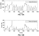
- FIG. 13A shows a plot of the speed of the flywheel.
- FIG. 13B shows a plot of the power loss of the flywheel.
- FIG. 14 shows a schematic diagram of a TESH powertrain.
- FIG. 15 is the flowchart of the high-level control process showing the operation modes in each of the high level modes.
- FIG. 16A and FIG. 16B show a general schematic diagram of a high-level control mode that has medium levels control modes and the criteria for transitions.
- FIG. 17 shows a plot of the results of the simulation for a conventional vehicle equipped with a manual transmission and the same ICE as in the TESH powertrain.
- FIG. 18 shows a plot of the results of the simulation for a parallel hybrid electric vehicle equipped with the same ICE and the same EM as the TESH powertrain.
- FIG. 19 shows a schematic diagram of a Tri-Energy Source Hybrid (TESH) system in accordance with the present description.
- TSH Tri-Energy Source Hybrid
- Hybrid Electric Vehicles equipped with an Internal Combustion Engine (ICE) and Electric Machine (EM) have been proven to be very effective at increasing fuel economy and reducing pollution and greenhouse gasses.
- ICE Internal Combustion Engine
- EM Electric Machine
- a third energy source and in particular an energy buffer, is introduced into the HEV powertrain to serve as an energy buffer to level the peak load of the powertrain.
- the energy buffer also referred to as a Short-term Energy Storage System (SESS)
- SESS Short-term Energy Storage System
- Improvement of the powertrain can also be achieved by downsizing the ICE and EM while the decreased power supply is compensated by the SESS.
- SESS Short-term Energy Storage System
- Several different options for SESS may be implemented: e.g. battery, fuel cells, supercapacitors, hydraulic accumulators, and flywheels.
- the main goal of introducing a third energy storage system into a HEV powertrain is to level the peak load of the primary and secondary energy system so that they can operate at better efficiencies.
- the third energy storage system, or SESS needs to have certain characteristics such as: the capability to charge and discharge, high power density, long lifetime, moderate energy density and high efficiency.
- flywheels are coupled to the end of the crankshaft to deliver a smooth power flow.
- the flywheel serving as the energy storage unit in Hybrid-Inertia powertrains is desired to have the same characteristics as the electrical energy storage, e.g. high robustness, high reliability, low initial cost and replacement costs, long calendar and cycle life, high specific energy, and high specific power.
- flywheel systems' specific energy is generally lower than the battery systems. For a small unit flywheel, its specific energy can reach 30 Wh/kg, including housing, electronic controllers, etc. Flywheel systems with advanced material have been predicted to reach a specific energy of 140 Wh/kg.
- HA Hydraulic Accumulator
- Hydraulic Accumulator SESS energy is stored in the compressed gas contained by the Hydraulic Accumulator vessel.
- An HA can be connected to the mechanical drive shaft via pump/motor so that the energy flow can be converted between the forms of hydraulic and kinetic.
- HA systems have high power density and long life cycles, and these are very desirable factors for a SESS.
- an HA system also has problems such as low efficiency and low specific energy.
- Flywheel systems have characteristics such as high specific power, low cost, long life time and moderate specific energy.
- One other important characteristic of a flywheel system is that the loss in the flywheel system is independent of the power flow. In other words, unlike a supercapacitor or battery, the efficiency of the flywheel will not increase when the power input/output of the system increases.
- HA and supercapacitor are both feasible solutions for SESS, the flywheel is specifically chosen in the embodiments described below, since frequent, high power charge and discharge of the flywheel system will not cause significant loss while flywheel system also has characteristics such as high power density, long lifetime and moderate energy density.
- FIG. 1 shows a schematic view of a first configuration of a Tri-Energy Source Hybrid (TESH) powertrain 10 a .
- Powertrain 10 a comprises a first branch including a flywheel 12 , continuously variable transmission (CVT) 14 , first clutch (clutch 1 ) 16 and gear set 18 .
- the flywheel/CVT branch is coupled to the powertrain at the output end of Electric Motor (EM) 24 , which powered by battery 26 and is coupled to Internal Combustion Engine (ICE) 20 through second clutch 22 .
- EM-EM branch is the primary energy source for powering the axles and vehicle 28 , and has no transmission.
- the Flywheel-CVT branch of powertrain 10 a is primarily used a peak leveling device.
- the Flywheel-CVT branch is stand-alone from the ICE 20 or EM 24 , so there is only one pathway, i.e. CVT 14 , for the flywheel 12 to charge/discharge energy.
- Variations of powertrain 10 a may be made by moving the coupling point to different locations of the powertrain while the characteristics of this type of powertrain remain the same.
- powertrain configuration 10 a The advantages of powertrain configuration 10 a are: a) the structure is relatively simple, and the control strategies are also simple as a result; b) the ICE 20 and EM 24 in the system can be downsized since peak propulsion and regeneration loads are leveled by the flywheel-CVT system, and c) the operations of ICE 20 and EM 24 both be kept at optimal points for efficiency at a given speed for most driving conditions.
- FIG. 2 shows a schematic view of a second configuration of a Tri-Energy Source Hybrid (TESH) powertrain 10 b where the EM 24 is directly linked to the drive shaft/vehicle axles 28 while ICE 20 is mechanically coupled to the flywheel 12 via a clutch.
- TSH Tri-Energy Source Hybrid
- the ICE 20 is connected to the drive shaft of axle 28 via a transmission, e.g. CVT 14 .
- the energy stored in the flywheel 12 can be charged from the CVT 14 or ICE 20 while it can only be discharged via CVT 14 .
- the speed of the flywheel 12 is limited by the speed range of the ICE 20 , since it is mechanically coupled to the ICE 20 .
- a first clutch 16 and gear set 18 are coupled between CVT 14 and vehicle axle 28 , and a second clutch 22 couples flywheel 12 and ICE 20 .
- Variations such as adding a gear set 18 between the ICE 20 and flywheel 12 , can be made for this powertrain, while the characteristics of the powertrain remain the same.
- Some advantages of the configuration of powertrain 10 b are: a) the flywheel 12 can be charged directly by the ICE 20 ; b) the ICE 20 and EM 24 can be downsized, since peak propulsion and regeneration loads are leveled by the flywheel 12 /CVT 14 system; c) the operations of ICE 20 and EM 24 can both be kept at an optimal points for efficiency at given speed for most driving conditions; and d) the CVT 14 also serves as the transmission for ICE 20
- Possible demerits of the configuration of powertrain 10 b are: a) an additional moment of inertia at the starting phase may be needed due to the flywheel 12 having a negative impact on low-speed acceleration performance; and b) the size of the CVT 14 is relatively large for this configuration since the power transmitted by it comes from both ICE 20 and flywheel 12 .
- FIG. 3 shows a schematic view of a third configuration of a Tri-Energy Source Hybrid (TESH) powertrain 10 c .
- the ICE 20 is linked to the axle 28 drive shaft through a third clutch 30 while the EM 24 is mechanically coupled to the flywheel 12 via clutch 22 .
- the EM 24 is connected to the axle 28 drive shaft via the flywheel 12 CVT 14 , first clutch 18 and drive set 18 .
- the energy stored in the flywheel 12 can be charged and discharged via CVT 14 or EM 24 .
- the speed of the flywheel 12 is limited by the speed range of the EM 24 since the flywheel 12 is mechanically coupled to EM 24 .
- Variations such as adding a transmission set (e.g. CVT) between ICE 20 and the axle 28 drive shaft or integrating the EM 24 rotor and the flywheel 12 , can be made while the characteristics of the powertrain remain the same.
- CVT a transmission set
- Some advantages of the configuration of powertrain 10 c are: a) the flywheel 12 can be charged and discharged directly by the EM 24 ; b) the ICE 20 and EM 24 can be downsized, since peak propulsion and regeneration loads are leveled by the flywheel 12 /CVT 14 system, c) the operations of the ICE 20 and EM 24 can both be kept at optimal points for both efficiency and emission for most driving conditions, and d) the CVT 14 also serves as the transmission for the EM 24 .
- Possible demerits of the configuration of powertrain 10 c are: a) an additional moment of inertia at the starting phase may be needed due to the flywheel 12 having a negative impact on low-speed acceleration performance; b) the size of the CVT 14 is relatively large since the power transmitted by it comes from both ICE 20 and EM 24 , and c) the ICE 20 is connected to the driveshaft without a transmission.
- a TESH powertrain configuration 10 d comprising a CVT 14 , flywheel 12 , and planetary gear set 36 is shown in FIG. 4 .
- the planetary gear set 36 is connected to the input shaft of CVT 14 , the output shaft of CVT 14 and flywheel 12 .
- the input shaft of CVT 14 is connected to first energy source 32 while the output shaft of the CVT 14 is connected to second energy source 34 and the axle 28 drive shaft. Energy flows into/out of the flywheel 12 via a planetary gear set 36 .
- TESH powertrain configuration 10 d is detailed in FIG. 4 as a general expression of possible configurations of a TESH powertrain comprising first energy source 32 , second energy source 34 , a flywheel 12 , CVT 14 , planetary gear set 36 .
- first energy source 32 comprises EM 24
- second energy source 34 comprises ICE 20
- first energy source 32 comprises ICE 20
- second energy source 34 comprises EM 24 .
- FIG. 4 does not specify which gear of the planetary gear set 36 is connected to the flywheel 12 , CVT 14 input shaft or CVT 14 output shaft. It is appreciated that different configurations can be easily implemented by connecting the sun gear, ring gear and planetary carrier (all not shown) of the planetary gear 36 set to the different shaft of the CVT 14 or flywheel 12 . Including the different locations of ICE 20 and EM 24 , the total number of possible configurations for the structure depicted in FIG. 4 is 12.
- powertrain 10 d Some advantages of the configuration of powertrain 10 d are: a) the power flow of the flywheel 12 is no longer restricted by the CVT 14 , b) the CVT 14 can serve as the transmission for the first energy source 32 , c) the operations of the ICE 20 and EM 24 can both be kept at optimal points for both efficiency and emission for most of driving conditions.
- Possible demerits of the configuration of powertrain 10 d are: a) The structure and control are relatively complicated, b) part of the energy flow from the flywheel 12 will travel through both CVT 14 and the planetary gear set 36 , the second energy source 34 is connected to the axle 28 driveshaft without a transmission.
- FIG. 5 shows a schematic view of a fifth exemplary configuration of a Tri-Energy Source Hybrid (TESH) powertrain 10 e .
- flywheel 12 is coupled to an HEV powertrain via a CVT 14 , first and second clutches 16 , 22 and gear set 18 .
- the flywheel/CVT branch is coupled to the powertrain at the output end of EM 24 , which powered by battery 26 and is coupled to ICE 20 through third clutch 30 .
- the ICE-EM branch is the primary energy source for powering the axles and vehicle 28 , and has no transmission but rather a final drive gear set 66 instead.
- the major components of TESH powertrain include a battery 26 , EM 24 , ICE 20 , flywheel 12 , CVT 14 and gear set 18 . It is beneficial to create easy to scale component models for the TESH powertrain, since sizing optimization of the components may be studied in the future. Many models, both generic and empirical, have been created these major components in previous studies.
- One of the most well-documented public databases of HEV components can be found in Advance Vehicle Simulator (ADVISOR).
- ADVISOR Advance Vehicle Simulator
- the data, such as efficiency of EM's and performance of the OCV curve of the battery 26 are either collected from published papers or experimentally tested at the National Renewable Energy Laboratory (NREL). With these data, quasistatic models of the EM 24 , ICE 20 and Battery 26 can be created.
- Fuel consumption of the ICE 20 which is defined by:
- ⁇ e is the engine speed
- ⁇ e is the thermodynamic efficiency
- T e is engine output torque
- P e is enthalpy flow
- H l the fuel's lower heating value
- ⁇ dot over (m) ⁇ f is the fuel mass flow.
- ⁇ e is also dependent on engine speed and torque.
- the engine efficiency is calculated from the fuel consumption data stored in the ADVISOR database. Scaling of the component can be achieved by multiplying the scaling factors by the speed or the torque range of the efficiency map.
- Electric machines e.g. electric motors and generators
- the electric machines are key components in the TESH configurations of the present description.
- the electric machines (e.g. EM 24 ) in HEV are reversible, i.e. they can transform electric energy into kinetic energy and transform kinetic energy into electric energy.
- the electric machine 1) converts electricity from the battery 26 to kinetic energy to propel the vehicle, 2) converts excessive propulsion from the engine to electricity, and 3) recovers kinetic energy when the vehicle slows down.
- the efficiency of the EM 24 is defined by Eq. 4:
- ⁇ m the motor efficiency
- T m the torque generated by the motor
- P b the power provided by the battery 26
- ⁇ m the motor speed.
- Positive torque means the motor is in traction mode
- negative torque means the motor is in generator mode.
- the internal resistance, induction and mechanical loss are predicted via several methods. This will lead to very different EM efficiencies. In this description, the efficiencies of the EM at a given speed and output torque ⁇ m (T m , ⁇ m ) is linearly interpolated from experimental data.
- Scaling of the EM component can be achieved by multiplying the scaling factors to the speed or the torque range of the efficiency map.
- the state of charge (SOC) of the battery is defined by:
- SOC is the non-dimensional state of charge
- Q(t) is the capacity of the battery 26
- Q max is the maximum capacity of the battery 26
- I b is the current drawn from the battery 26 .
- a positive I b means the EM 24 operates as a motor and a negative I b means the EM 24 operates as a generator.
- U b is the voltage input from the battery 26 .
- the Rint model is implemented for battery 26 cell modeling in the following sections.
- a NiMH battery 26 cell is chosen from the ADVISOR database for its moderate specific energy, moderate specific power and low cost compared to the other three battery 26 chemical choices.
- the efficiency of the battery 26 , ⁇ b can be derived:
- ⁇ n ⁇ ( SOC , I b ) ⁇ e cou ⁇ U oc ⁇ ( SOC ) - I b ⁇ R i ⁇ ( SOC ) U oc ⁇ ( SOC ) , discharge e cou ⁇ U oc ⁇ ( SOC ) U oc ⁇ ( SOC ) - I b ⁇ R i ⁇ ( SOC ) , charge Eq . ⁇ 7 where e cou is the coulombic efficiency.
- Scaling of the battery 26 pack can be achieved by changing the number of battery 26 cells in the battery 26 pack.
- the SOC is estimated using Eq. 5, Eq. 6 and battery current I b established by Eq. 8:
- I b U oc - U oc 2 - 4 ⁇ P b ⁇ R i 2 ⁇ R i . Eq . ⁇ 8
- the transmission devices transmit mechanical power while regulating the output torque and speed.
- the major power transmission devices are the continuously variable transmission (e.g. CVT 14 ) and gear set 18 (also referred to as gear box.
- ⁇ 1 the efficiency of the automotive gear set 18 , is generally between 0.95 and 0.97.
- ⁇ cvt the efficiency of CVT 14 , is a function of input torque, input speed and CVT 14 gear ratio.
- the CVT comprises a hydraulic actuated push belt CVT 14 .
- CVT 14 efficiency decreases with increasing input speed and decreasing input torque, and reaches maximal values for a gear ratio equal to one.
- the efficiency of the CVT 14 can be maintained in the range between 0.90 and 0.95.
- FIG. 6 shows a schematic diagram of an exemplary ring flywheel 12 and its housing.
- ⁇ fw is the speed of the flywheel 12
- d is the flywheel 12 diameter at rim 40
- u is the maximum linear speed of the flywheel 12
- d w is the diameter of the flywheel 12 shaft 42 with arms 46 connecting the rim 40 and shaft 42
- ⁇ and q are the non-dimensional coefficients.
- the flywheel 12 moment of inertia is denoted as J fw and is calculated according to:
- flywheel 12 As an energy storage system, one of the most important characteristics of the flywheel 12 is the capacity of stored energy. From Eq. 13 and Eq. 14, the capacity is limited by the maximum yielding strength of flywheel 12 rotor material and the maximum rotational speed of the flywheel 12 .
- the power loss of the flywheel 12 is denoted as P l .
- P l takes into account both P a , i.e. air resistance loss, and P b , i.e. bearing loss.
- P a 0.04 ⁇ a 0.8 ⁇ a 2.8 ( t ) ⁇ d 1.8 ⁇ ( ⁇ +0.33)
- ⁇ a and ⁇ a are the dynamic viscosity and density of air in the flywheel 12 chamber, and:
- T l 0.0574 ⁇ a 0.8 ⁇ a 0.2 ⁇ d 4.8 ⁇ ( ⁇ +0.33) ⁇ fw 1.8 +0.5 ⁇ k ⁇ d w ⁇ m f ⁇ g.
- the maximum speed of the flywheel 12 is limited by the maximum speed of the ICE 20 or EM 24 .
- TESH powertrain configuration 10 a shown in FIG. 1 is modeled and simulated.
- FIG. 7 shows a schematic diagram of a quasi-static model of a SESS subsystem 50 incorporating a flywheel 12 /CVT 14 power source.
- the flywheel 12 is connected to the input end of the CVT 14 while the output end of the CVT 14 is connected to the drive shaft (axle 28 ) via a gear set 18 .
- T 1 , T 2 , and T 3 are the torque applied to the CVT 14 input end, the torque applied to the input end of the gear set 18 and the torque applied to the driveshaft, respectively.
- ⁇ fw , ⁇ cvt and ⁇ s are the speed of the flywheel 12 , the speed of the CVT 14 output end, and the speed of the driveshaft, respectively.
- the gear ratio of CVT 14 is r and the change rate of this gear ratio is denoted as ⁇ dot over (r) ⁇ .
- the control output ⁇ dot over (r) ⁇ from the CVT 14 controller 52 can be derived from Eq. 9. Eq. 10 and Eq. 19 to yield:
- r . - [ T l * r cvt + T 2 ⁇ ⁇ cvt sign ⁇ ( - T 2 ) J fw ⁇ r cvt + r cvt ⁇ ⁇ . cvt ] / ⁇ cvt . Eq . ⁇ 20
- FIG. 8 shows a schematic diagram of a quasi-static model of TESH powertrain 60 incorporating the SESS subsystem 50 of FIG. 7 with torque demand T 3 (T shaft ), including ICE 20 , clutch 16 , EM 24 , battery 26 , final drive 66 , gear set 18 , and vehicle axle 28 according to velocity profile 62 .
- J eq ⁇ dot over ( ⁇ ) ⁇ w T w ⁇ T road .
- J eq is the equivalent moment of inertia of the vehicle mass and the rotational parts in the powertrain
- ⁇ w is the wheel speed
- T w is the torque at wheel
- T road is the equivalent torque of the road load.
- ⁇ f , ⁇ 1 and ⁇ c are the efficiency of the final drive 66 , gear set 18 , and CVT 14 , respectively.
- r f , r 1 and r are the gear ratio of the final drive 66 , gear set 18 , and CVT 14 , respectively.
- J e and J m are the moment of inertia of the engine and EM 24 , respectively.
- the moment of inertia of flywheel 12 and CVT 14 are not included in Eq. 23, as they are included in dynamic equations of the SESS 50 such as Eq. 18.
- T road R w ⁇ [0.5 ⁇ C D ⁇ A F ⁇ V rel 2 +m v ⁇ g ⁇ (cos ⁇ C R +sin ⁇ )], Eq. 25 where ⁇ , C D A F , V rel , g, C R , ⁇ are the density of the air, aerodynamic drag coefficient, vehicle area normal to the direction of travel, gravitational constant, rolling resistance coefficient, and inclined angle of road.
- the battery 26 model used in the quasi-static approach/backward facing approach is the Rint model.
- a Simulink model used for simulating the drivetrain of the present description utilizes a gear set 18 connected to the CVT 14 output end that is integrated into the CVT 14 for simplicity.
- the high-level strategy of the Simulink model is:
- the control modules of the vehicle collect shaft speed, shaft acceleration, shaft torque demand, battery SOC and CVT 14 gear ratio then calculates the torque demands sent to the ICE 20 , motor and SESS.
- ICE 20 model With the torque demand and shaft speed from the controller, ICE 20 model returns the fuel consumption rate; the CVT 14 /flywheel 12 system returns the CVT 14 gear ratio and the EM 24 returns the electric power to calculate the battery SOC.
- a controller (not shown) generates torque demands to ICE 20 , EM 24 , and SESS 50 .
- the shaft speed and the shaft torque demand are the inputs to this controller, while the controller also collects more information such as the SOC of the battery 26 , gear ratio rate of the CVT 14 , etc.
- optimization control algorithms have been developed for hybrid vehicle powertrains such as fuzzy logic controls, equivalent consumption minimization strategies and dynamic programming control, a rule-based control algorithm was used and implemented in simulations.
- a high-level control algorithm of TESH powertrain control incorporates vehicle high-level modes including stop mode, regenerative braking mode, and propulsion mode.
- the propulsion mode can be further divided into high-speed and low-speed mode since during propulsion mode, the engine only operates above a certain speed to ensure a high fuel efficiency.
- the different operation modes can be then further divided by the 18 operation modes according to different operating states of the ICE 20 , EM 24 , and SESS 50 .
- +1, 0, ⁇ 1 represents the positive torque, zero torque, and negative torque, respectively, for ICE 20 , EM 24 , and SESS 50 .
- Table 5 demonstrates the operation modes shown in Table 4 that are associated with the three High-Level Modes of the TESH Powertrain.
- the vehicle specs are extracted from an existing class 5 truck and the specs of the major components are chosen from the ADVISOR data base.
- the drive cycle chosen for this simulation is the Urban Dynamometer Driving Schedule (UDDS) drive cycle.
- the UDDS drive cycle is normally recommended for light-duty vehicle testing by the Environment Protection Agency (EPA), due to its volatile accelerations.
- EPA Environment Protection Agency
- the simulated vehicle is a class 5 truck, UDDS is chosen to test the performance of the TESH powertrain in which ICE 20 and EM 24 are mechanically coupled to the drive shaft without a transmission.
- An important goal of the simulation is to establish that the TESH powertrain if the present description is capable of delivering the traction and brake torques to meet the drive cycle with all the components of the powertrain operating within their rated limits.
- FIG. 9A shows a plot of the torque demand at the shaft and FIG. 9B shows a plot of the resulting torque supplied by the ICE 20 , EM 24 , and SESS 50 individually.
- FIG. 9A illustrates that the torque demands at driveshaft are met with only a few discrepancies caused by the discrete nature of the simulation.
- FIG. 10A shows a plot of the torque supplied by the ICE 20
- FIG. 10B shows a plot of the efficiency of the ICE 20 .
- FIG. 11 shows a plot of the torques supplied by the EM 24 .
- FIG. 11 illustrates shows the EM 24 operates within its torque limits. More importantly, FIG. 11 confirms that EMs in current TESH configuration with the heuristically designed control algorithm operates very often at optimal efficiency operation states compared to typical EMs in HEV.
- FIG. 12 shows a plot of the gear ratio of the CVT 14 .
- FIG. 12 demonstrates that the SESS 50 is frequently charged and recharged during the drive cycle within its gear ratio range.
- FIG. 13A shows a plot of the speed of the flywheel 12 .
- FIG. 13B shows a plot of the power loss of the flywheel 12 .
- FIG. 13A illustrates that the maximum speed of the flywheel 12 during the drive cycle is only 3500 RPM, which is significantly lower than the speed limit of the steel flywheel 12 chosen for the simulation.
- the power loss due to aerodynamic drag and bearing friction in a sealed but non-vacuum flywheel 12 chamber peaked at 400 W while it remains below 200 W for the majority of the drive cycle.
- the results of the simulation show that all the major components in the TESH powertrain work inside their limits when they provide adequate traction and regenerative braking torques for the vehicle to meet the velocity of the drive cycle.
- the simulation results indicate that the TESH powertrain and its control strategy have promising features, such as both the ICE 20 and EM 24 operating at high-efficiency range while the energy loss in SESS 50 due to the aerodynamic drag and bearing friction is kept relatively low.
- the demonstrated TESH powertrain may be configured to scale the components of the TESH powertrain to reach optimization goals such as weight, cost, and fuel economy of the powertrain.
- the rule-based control strategy in this chapter is designed heuristically and yields an adequate simulation result. Different optimization controls may also be implemented for the disclosed powertrain configuration to produce better fuel economy and emissions.
- TESH powertrains e.g. TESH powertrains detailed in FIG. 1 through FIG. 5
- TESH powertrains detailed in FIG. 1 through FIG. 5
- the Dynamic Programming (DP) is implemented first, and the result of it is used as a baseline since it delivers the global optimal.
- the rule-based control strategy is designed and tuned for a particular drive cycle in an attempt to match the baseline results.
- the third control strategy is an Equivalent Consumption Minimization Strategy derived for the TESH powertrain incorporating the energy dissipation effect in the SESS.
- FIG. 14 shows one possible TESH configuration 70 , comprising a Primary Energy Source (PES) 72 , Secondary Energy Source (SES) 74 , Energy Convertor (EC) 76 , Short-term Energy Storage System (SESS) 50 , Power Distributer (PD) 78 final drive 66 and vehicle axles 28 according to driving cycle 80 .
- PES Primary Energy Source
- SES Secondary Energy Source
- EC Energy Convertor
- SESS Short-term Energy Storage System
- PD Power Distributer
- P P , P ses , P s , P sess , and P shaft are the power supplied by the PES 72 , SES 74 , EC 76 , SESS 50 , and the driveshaft of axles 28 .
- the + sign on the arrow denotes the positive power flow directions.
- the ICE 20 is the PES 22
- the battery 26 is the SES
- the EM 24 is the EC 76
- the PD 78 is gear set 18 .
- the SESS 50 comprises of a flywheel 12 and a mechanical CVT 14 as detailed in FIG. 7 .
- the quasi-static model of the TESH powertrain may be seen with reference to model 60 shown in FIG. 8 .
- the power demand for the vehicle P veh (t) follows the drive cycle 80 and it is a function of time.
- Some of the goals for optimization in a control problem of a TESH powertrain include fuel consumption, nitrogen oxide emission, and hydrocarbon emission.
- the state of charges for SES 74 and SESS 50 are SOC ses (t) and SOC sess (t), detailed definitions for which are discussed below with specific technology choices for the energy storage system.
- the general constraint for the input u(t) is defined as: u ( t ) ⁇ U ( t ). Eq. 37 where U(t) is the set of admissible controls that satisfy the conditions described in Eq. 29 to Eq. 32.
- SOC(t) is the state of charge of the battery 26 ; r cvt (t) is the gear ratio of the CVT 14 ; P b (t) is the power output of the battery 26 ; and P sess (t) is the power output of the SESS 50 .
- the gear ratio of the CVT 14 is chosen as one of the state variables instead of the percentage ratio of the energy stored in the flywheel 12 to the maximum energy storage capacity of the flywheel 12 at the instance. Since the maximum speed of the flywheel 12 continue to charge with the speed of the driveshaft due to the mechanical coupling between the flywheel 12 and drive shaft, the maximum energy the flywheel 12 is capable of storing keeps changing.
- P b (t), P sess (t), SOC(t), and r cvt (t) are defined as the following:
- the dynamic equation of state of charge of the battery 26 can be written as:
- r . cvt ⁇ ( x , u , t ) - [ T l ⁇ ( r cvt , t ) ⁇ r cvt + T 2 ⁇ ⁇ cvt sign ⁇ ( - T 2 ) ⁇ ( r cvt , P sess ) J fw ⁇ r cvt + r cvt ⁇ ⁇ .
- T 1 (t) is the torque loss in the flywheel 12 . While T 1 (t) can be obtained experimentally or analytically, in the present description this loss is obtained analytically.
- ⁇ dot over (m) ⁇ f which is the fuel flow rate, can be expressed as a function of the state variables, control inputs and time.
- ⁇ dot over (m) ⁇ f f ( T e ( x,u,t ), ⁇ e ( t )).
- the speed of the engine i.e. ⁇ e (t)
- ⁇ e (t) The speed of the engine, i.e. ⁇ e (t)
- ⁇ e ⁇ ( t ) ⁇ v ⁇ ( t ) ⁇ r f R w ⁇ ⁇ when ⁇ ⁇ the ⁇ ⁇ clutch ⁇ ⁇ is ⁇ ⁇ enaged 0 ⁇ ⁇ when ⁇ ⁇ the ⁇ ⁇ cltuch ⁇ ⁇ is ⁇ ⁇ disengaged Eq . ⁇ 60
- r f is the gear ratio of the final drive 66 and R w is the radius of the wheels.
- T e The torque provided by the engine, i.e. T e can be expressed as:
- ⁇ f , ⁇ g , and ⁇ m are the efficiency of the final drive 66 , gear set 18 and electric motor respectively.
- ⁇ m is a function of P b , i.e. u 1
- ⁇ s (t) while ⁇ f and ⁇ g are considered constants.
- the power consumption i.e. P veh
- P veh P m ,P ses ,t
- m eq P m ,P sess ,t
- F road is the resulting force of the road loads including aerodynamic drag, rolling resistance and force due to the slope of the road.
- m eq m v + ( J e + J m ) ⁇ r f 2 ⁇ ⁇ f sign ⁇ ( - T 4 ) R w 2 , Eq . ⁇ 63
- m v is the mass of the vehicle
- ⁇ f , ⁇ 1 and ⁇ c are the efficiency of the final drive 66 , gear set 18 , and CVT 14 , respectively.
- r f , r 1 and r are the gear ratio of the final drive 66 , gear set 18 , and CVT 14 , respectively.
- the equivalent mass excludes the factor of the flywheel's moment of inertia for the moment of inertia of the flywheel 12 is calculated separately in the dynamic equation of the flywheel 12 , which is incorporated in the SESS 50 .
- the flywheel 12 serves as an active energy storage unit via the control of the CVT 14 ; the energy dissipation due to aerodynamic drag and friction in the flywheel 12 chamber are taken into account during the calculation of the output torque of the SESS 50 , as well as the dynamic effect of the flywheel 12 .
- F road 0.5 ⁇ C D ⁇ A F ⁇ V rel 2 +m v ⁇ g ⁇ (cos ⁇ C R +sin ⁇ ), Eq. 64 where ⁇ , C D A F , V rel , g, C R , ⁇ are the density of the air, aerodynamic drag coefficient, vehicle area normal to the direction of travel, gravitational constant, rolling resistance coefficient, and inclined angle of road.
- the control strategies can be categorized as a rule-based control strategy, e.g. deterministic rule-based and fuzzy logic rule-based controls, and optimization based control strategy, e.g. equivalent consumption minimization, dynamic programming and genetic algorithm control strategy.
- Dynamic Programming DP
- the second control strategy used is the Heretically Designed Rule-Based (HDRB) control strategy.
- the goal of implementation of the HDRB control strategy is to reach an acceptable fuel economy result compared to the results generated by the DP.
- ECM Equivalent Consumption Minimization strategy
- PMP Pontryagin's Minimum Principle
- J ( u ( t )) G ( x ( t f ))+ ⁇ t 0 t f ⁇ dot over (m) ⁇ f dt.
- J ⁇ (x 0 ) is the cost of applying control policy ⁇
- g N (x N ) is the cost of the final time step
- ⁇ N (x N ) is the penalty function of the final state
- ⁇ k (x k ) is the penalty function at the time step k
- h k (x k , ⁇ k (x k )) is the cost of implementing control ⁇ k (x k ) at state x k .
- ⁇ 0 is defined as the optimal control policy that minimizes J ⁇ :
- the cost-to-go function J k (x i ) is evaluated at each time step.
- the intermediate cost-to-go function is defined as:
- J k ⁇ ( x i ) min u k ⁇ U k ⁇ ⁇ h k ⁇ ( x i , u k ) + ⁇ k ⁇ ( x i ) + J k + 1 ⁇ ( F x ⁇ ( x i , u k ) ) ⁇ . Eq . ⁇ 70
- the basic algorithm of Dynamic Programming is to calculate for the minimum cost-to-go function backward in time and output the ⁇ 0 .
- the cost-to-go function J k+1 (F x (x i ,u k ) can be found via nearest-neighbor approximation or other advanced interpolation schemes. In the simulation of this section, linear interpolation is used to reduce the computational cost.
- control inputs i.e. u(t)
- state variables x(t) remain the same as defined in Eq. 43 and Eq. 44.
- the dynamic equations of the state variables, i.e. Eq. 53 and Eq. 54 can be rewritten as:
- T s is the time step that is set to be 1 second.
- Matlab function is used to simulate a chosen vehicle.
- RBC Rule-Based Control strategies
- the Rule-Based Control strategies won't guarantee a global optimal for the control problem.
- RBC Rule-Based Control strategies
- the second step is to create the control rules that dictate the transmissions among these modes by setting criteria such as SOC levels and shaft speed levels.
- the third step of the RBC design involves tuning the RBC in a simulated environment to generate desirable results.
- the maximum number of operation modes for a dual-energy source hybrid powertrain e.g. HEV
- the modes include stop mode, pure engine mode, pure electric mode, hybrid mode, regenerative braking mode and charge sustaining mode.
- an RBC for the TESH powertrain uses as many as 18 modes to fully define all possible combinations of the three energy sources' operational states.
- Table 4 shows all the possible modes and the corresponding operation states of the ICE 20 , EM 24 , and SESS.
- +1, 0, ⁇ 1 represent the positive torque, zero torque, and negative torque respectively, for ICE 20 , EM 24 , and SESS 50 .
- FIG. 15 is the flowchart of the high-level control 100 of RBC and Table 5 shows the operation modes in each of the high level modes.
- the stop mode 112 is for the vehicle at stop and the braking mode 118 is for the vehicle during braking, while the low speed 114 and high-speed 116 modes are for propulsion.
- Input data 102 e.g. states of the system x(t), auxiliary function G(x), shaft torque demand T shaft
- Input data 102 is evaluated and at box 104 . If vehicle speed is not >0, the torque demand at the driveshaft is evaluated at box 106 . If the torque demand at the driveshaft is not >0, stop mode 112 is applied. If the torque demand at the driveshaft is >0, low speed mode 114 is applied.
- the torque demand at the driveshaft is evaluated at box 108 .
- breaking mode 118 is applied. If the torque demand at the driveshaft is not ⁇ 0, breaking mode 118 is applied. If the torque demand at the driveshaft is ⁇ 0, shaft speed is compared with ICE cut-off speed at evaluation box 110 . If the shaft speed is >the ICE cut-off speed, the high speed mode 116 is applied. If the shaft speed is not >the ICE cut-off speed, the low speed mode 114 is applied.
- the ICE 20 is shut off in the low-speed mode 114 due to the low efficiency of the ICE 20 at low speeds.
- the threshold value of the engine speed that decides whether the engine is turned-off is denoted as the engine cut-off speed. This engine cut-off speed may be used as a design parameter for further tuning in simulation to generate better fuel economy.
- the ICE 20 , EM 24 , and SESS 50 are all shut off, but the other three high-level modes comprise of multiple operation modes.
- Table 5 there are five modes in Low-Speed Mode and Braking mode. There 20 possible transitions among modes in either Low-Speed Mode or Braking mode. It is challenging to design a High-Speed Mode that has 14 operation modes and 182 possible transitions.
- the medium level control modes are created according to the torque demands at shaft.
- FIG. 16A and FIG. 16B show a general schematic diagram of a high-level control mode 120 that has medium levels control modes and the criteria for transitions.
- the torque demand at the driveshaft is input at block 122 , and evaluated at decision blocks 124 through 140 for specified criteria within each block (e.g. opt1, max1, max2, max3, as compared to shaft torque demand). Results at each decision block 124 through 140 determine the appropriate medium mode 150 through 167 (Medium Mode 1 through Medium Mode 7).
- FIG. 16A and FIG. 16B show the medium level flow chart of the high speed mode
- this type of tree-shaped control algorithm may be used for the transmissions among the five operation modes in low-speed propulsion mode.
- the total number of possible transitions among all 14 operation modes is 182.
- Table 6 shows the threshold values for the various criteria used in FIGS. 16A and 16B .
- opt1, max1, max2, and max3 are threshold values for torque supplies from ICE 20 , EM 24 , and SESS 50 . The values of these thresholds can be tuned according to the goals of optimization.
- Table 6 shows two possible sets of threshold values.
- T e,opt is the possible torque supplied by the engine at the instance with maximum fuel efficiency
- T e,max is the maximum torque supplied by the engine at the instance
- T m,opt is the possible torque supplied by the EM 24 at the instance with maximum fuel efficiency
- T m,max is the maximum torque supplied by the EM 24 at the instance
- T sess,max is the maximum torque supplied by the SESS 50 at the instance.
- Threshold value set 1 focuses on operating the engine at high efficiency while threshold value set 2 also allows EM 24 to operate at high efficiency.
- the criteria for activating the operational modes is the state of charge of the battery 26 and the gear ratio of the CVT 14 .
- energy in SESS 50 is frequently used compared to the energy in battery 26 , e.g. SESS 50 provides maximum power output and recapture.
- the CVT 14 has physical limits for its gear ratio while the high and low boundaries of battery SOC need to be set to prevent damaging the battery 26 .
- CVT 14 has a physical minimum gear ratio and maximum ratio, soft limits are also needed to reserve a small amount of the capacity of the SESS 50 .
- ECM Equivalent Consumption Minimization Strategy
- G(x,u,t) we need to take the time derivatives to the order of n so that in G (n) (x,u,t), u 1 (t), u 2 (t) are explicitly shown for the first time. From Eq. 75, the order n is clearly 1 :
- the Hamiltonian function of the system can be written as:
- H ⁇ ( x , u , t ) ⁇ m . f ⁇ ( t , u ) + ⁇ 1 ⁇ f 1 ⁇ ( x 1 , u 1 ) + t ⁇ A ⁇ 2 ⁇ f 2 ⁇ ( x 2 , u 2 ) + ⁇ 1 , 1 ⁇ f 1 ⁇ ( x 1 , u 1 ) m .
- ⁇ 1 and ⁇ 2 are co-states. According to PMP, ⁇ 1 exists and it is greater or equal to zero while the constraints of the state are active. Although PMP states that ⁇ 1,1 , ⁇ 1,2 , ⁇ 1,3 , and ⁇ 1,4 are unknown, they can be found by trial-and-error.
- the optimal control trajectory u 0 (t) and the optimal state trajectory x 0 (t) satisfy the following conditions for t ⁇ [t 0 ,t f ]:
- ⁇ 1,1 , ⁇ 1,2 , ⁇ 1,3 , and ⁇ 1,4 can be replaced by the same parameter ⁇ 1 as long as it is big enough since the results are not sensitive to it. From Eq. 75,
- ⁇ f 1 ⁇ ( x 1 , u 1 ) ⁇ x 1 ⁇ ⁇ and ⁇ ⁇ ⁇ f 2 ⁇ ( x 2 , u 2 ) ⁇ x 2 can be written as:
- ⁇ ⁇ f 1 ⁇ ( x 1 , u 1 ) ⁇ x 1 sign ⁇ ( u 1 ) ⁇ u 1 E b , max ⁇ ⁇ b sign ⁇ ( u 1 ) + 1 ⁇ ⁇ ⁇ b ⁇ x 1 Eq .
- ⁇ . 1 o ⁇ ( t ) ⁇ - sign ⁇ ( u 1 ) ⁇ ⁇ 1 o ⁇ u 1 E b , max ⁇ ⁇ b sign ⁇ ( u 1 ) + 1 ⁇ ⁇ ⁇ b ⁇ x 1 for ⁇ ⁇ t ⁇ ( A ⁇ C ) - sign ⁇ ( u 1 ) ⁇ ( ⁇ 1 o ⁇ ⁇ 1 ) ⁇ u 1 E b , max ⁇ ⁇ b sign ⁇ ( u 1 ) + 1 ⁇ ⁇ ⁇ b ⁇ x 1 for ⁇ ⁇ t ⁇ ( A ⁇ C ) Eq . ⁇ 81 ⁇ .
- H ⁇ ( x , u , t ) m . f ⁇ ( t , u ) - ( ⁇ 1 + p ⁇ ( x 1 ) ) ⁇ ( u 1 E b , max ⁇ ⁇ b sign ⁇ ( u 1 ) ) - ( ⁇ 2 + q ⁇ ( x 2 ) ) ⁇ ( [ T 1 ⁇ ( r cvt , t ) ⁇ r cvt ⁇ ⁇ cvt + u 2 ⁇ ⁇ cvt sign ⁇ ( - u 2 ) + J fw ⁇ r cvt 2 ⁇ ⁇ cvt ⁇ ⁇ .
- PMP transforms the optimization problem of the cost function over a certain time span into an instantaneous minimization of the Hamiltonian.
- the Equivalent Consumption Minimization Strategy requires more transformation of the Hamiltonian to reach a more intuitive expression for instant minimization.
- the first step of the transformation is to create a reduced Hamiltonian H :
- H _ ⁇ ( x , u , t ) m . f ⁇ ( t , u ) - ( ⁇ 1 + p ⁇ ( x 1 ) ) ⁇ u 1 E b , max ⁇ ⁇ b sign ⁇ ( u 1 ) - ( ⁇ 2 + q ⁇ ( x 2 ) ) ⁇ u 2 J fw ⁇ r cvt ⁇ ⁇ cvt 2 ⁇ ⁇ cvt sign ⁇ ( u 2 ) .
- H _ ⁇ ( x , u , t ) m . f ⁇ ( t , u ) + s 1 ⁇ ( 1 + p ⁇ ( x 1 ) ⁇ 1 ) ⁇ u 1 Q lhv + s 2 ⁇ ( 1 + q ⁇ ( x 2 ) ⁇ 2 ) ⁇ u 2 Q lhv , ⁇ ⁇ where ⁇ ⁇ ( 1 + p ⁇ ( x 1 ) ⁇ 1 ) ⁇ ⁇ and ⁇ ⁇ ( 1 + q ⁇ ( x 2 ) ⁇ 2 ) Eq . ⁇ 89 are penalty functions that are not 1 only when the state constraint is active.
- Q lhv is the lower heating value of the fuel and the control inputs are power demands, so that
- u i Q lhv can be considered as fuel mass flow rate.
- the definition of the equivalent fuel mass flow rates for SES and SESS are shown as following:
- the backward facing simulation model of the TESH powertrain was created in Matlab Simulink based on the quasi-static model shown in FIG. 14 .
- the specifications of the vehicle, diesel engine, EM 24 and battery 26 module specifications are chosen from the ADVISOR database.
- the first implemented control strategy here is the Dynamic Programming strategy.
- DP guarantees a global optimal, it is not a suitable candidate for real-time because of its computationally intense process.
- DP is implemented purely to provide a baseline result for comparison with the other two control strategies.
- the fuel economy generated by DP is 16.4 miles per gallon.
- the rule-based design control strategy can be implemented in real time. However, it does not provide a global optimal. Despite the tuning and modification of the RCS, the best fuel economy of this drive cycle is 13.54 miles per gallon.
- Eq. 90 and Eq. 91 can be rewritten as:
- m . electric ⁇ s 1 , ch ⁇ ( 1 + p ⁇ ( x 1 ) ⁇ 1 ) ⁇ u 1 Q lhv for ⁇ ⁇ u 1 ⁇ 0 s 1 , ch ⁇ ( 1 + p ⁇ ( x 1 ) ⁇ 1 ) ⁇ u 1 Q lhv ⁇ ⁇ b , avg 2 for ⁇ ⁇ u 1 ⁇ 0 ⁇ Eq . ⁇ 93 m .
- tuning range is from 1 to 4 since it represents the factor for charging the energy storage system with ICE 20 .
- the tuning range is from 50% to 100%.
- m electric s 1 , ch , opt ⁇ ⁇ b , avg , opt sign ⁇ ( ⁇ ⁇ ⁇ SOC ) ⁇ ( - ⁇ ⁇ ⁇ SOC ) ⁇ E b , max Q lhv . Eq . ⁇ 97
- the augmented fuel consumption of the ECM simulation is smaller than the fuel consumption of the ICE 20 , hence resulting in an augmented fuel economy at 15.6 miles per gallon. Since the SOC change in the DP simulation is not significant enough, the power augmented fuel economy for DP remains at 16.4 miles per gallon. After implementation of this augmentation, the augmented fuel economy of the RBC simulation is 14.8 miles per gallon.
- FIG. 17 shows a plot of the results of the simulation for a conventional vehicle equipped with a manual transmission and the same ICE 20 as in the TESH powertrain.
- the built-in powertrain control of the manual transmission powertrain obviously missed the high efficiency operating region and the fuel economy of this conventional powertrain was 9.2 MPG.
- FIG. 18 shows a plot of the results of the simulation for a parallel hybrid electric vehicle equipped with the same ICE 20 and the same EM 24 as the TESH. From FIG. 18 , it is clear that the ICE 20 shuts down very often for the vehicle to run at pure electric mode and the operation points still concentrate in the low efficiency region. The fuel economy of this parallel hybrid electric powertrain for UDDS drive cycle is 14 MPG.
- the TESH powertrain's operation actually allows the ICE 20 to operate more often at the high efficiency region and provide a better fuel economy than the control strategies implemented by ADVISOR.
- DP, RBC and ECM are implemented on the TESH powertrain model that was developed in the previous chapter.
- the simulation results of DP, RBC and ECM control strategies implemented on the TESH powertrain model can be summarized as following:
- the RBC method takes a significant amount of time to design, debug and tune due to the 18 possible modes of the TESH powertrain, but the controller can be implemented in real time.
- the DP method takes around 42 minutes to generate the global optimal with a properly chosen grid, while tuning to obtain the proper grid takes hours of trial and error effort. Since the information of the drive cycle is known a prior, the DP controller cannot be implemented in real time.
- the ECM controller can be implemented in real time. However, to reach a fuel economy that is close to the global optimal, there are four control parameters that need to be tuned by trial and error. The tuning process will take hours or even days without a proper tuning range.
- the augmented fuel economy of the TESH powertrain in UDDS drive cycle is 14.8 MPG, 15.6 MPG, and 16.4 MPG for RBC, ECM, and DP respectively.
- Further simulation tool and control strategies may include: 1) refinement of the RBC for a better fuel economy, 1) modifying the ECM with adaptive control parameters that are automatically tuned during the drive cycle to increase the robustness of the system, 3) simulate different drive cycles to test the capability of the control strategies and the powertrain. For example, highway drive cycles can be simulated to test the fuel economy of the TESH for long haul situations.
- both the ICE 20 and the EM 24 are capable of running at speed higher than the highest speed of the UDDS drive cycle.
- Different powertrain topologies and different component sizes maybe implemented to find the optimal powertrain configuration for different drive cycles.
- Table 1 and Table 2 present embodiments of computer programming instructions for implementing the methods technology described herein.
- FIG. 19 shows a schematic diagram of a Tri-Energy Source Hybrid (TESH) system 200 in accordance with the present description.
- TESH system 200 may comprise any of the TESH powertrain configurations 10 a through 10 e shown in FIG. 1 through FIG. 5 .
- TESH system 200 includes a controller/computing device 202 that includes application programming 206 that may include code, as provided in Table 1 or Table 2, or other instructions for implemented any of the methods detailed above, the instructions being stored in memory 208 and executable on processor 204 .
- Application programming 206 may also comprise instructions for receiving component data 210 (e.g. torque and velocity values, etc.) and providing commands 212 for controlling one or more components (e.g.
- the controller 202 receives data from and controls operation of flywheel 12 and CVT 14 for interoperation with the ICE 20 and EM 24 and battery 26 the programming further configured for splitting power among multiple energy sources, e.g. ICE 20 , EM 24 and SESS 50 to control load leveling and power surges for optimizing vehicle operating efficiency.
- Embodiments of the present technology may be described herein with reference to flowchart illustrations of methods and systems according to embodiments of the technology, and/or procedures, algorithms, steps, operations, formulae, or other computational depictions, which may also be implemented as computer program products.
- each block or step of a flowchart, and combinations of blocks (and/or steps) in a flowchart, as well as any procedure, algorithm, step, operation, formula, or computational depiction can be implemented by various means, such as hardware, firmware, and/or software including one or more computer program instructions embodied in computer-readable program code.
- any such computer program instructions may be executed by one or more computer processors, including without limitation a general purpose computer or special purpose computer, or other programmable processing apparatus to produce a machine, such that the computer program instructions which execute on the computer processor(s) or other programmable processing apparatus create means for implementing the function(s) specified.
- blocks of the flowcharts, and procedures, algorithms, steps, operations, formulae, or computational depictions described herein support combinations of means for performing the specified function(s), combinations of steps for performing the specified function(s), and computer program instructions, such as embodied in computer-readable program code logic means, for performing the specified function(s).
- each block of the flowchart illustrations, as well as any procedures, algorithms, steps, operations, formulae, or computational depictions and combinations thereof described herein can be implemented by special purpose hardware-based computer systems which perform the specified function(s) or step(s), or combinations of special purpose hardware and computer-readable program code.
- these computer program instructions may also be stored in one or more computer-readable memory or memory devices that can direct a computer processor or other programmable processing apparatus to function in a particular manner, such that the instructions stored in the computer-readable memory or memory devices produce an article of manufacture including instruction means which implement the function specified in the block(s) of the flowchart(s).
- the computer program instructions may also be executed by a computer processor or other programmable processing apparatus to cause a series of operational steps to be performed on the computer processor or other programmable processing apparatus to produce a computer-implemented process such that the instructions which execute on the computer processor or other programmable processing apparatus provide steps for implementing the functions specified in the block(s) of the flowchart(s), procedure (s) algorithm(s), step(s), operation(s), formula(e), or computational depiction(s).
- programming or “program executable” as used herein refer to one or more instructions that can be executed by one or more computer processors to perform one or more functions as described herein.
- the instructions can be embodied in software, in firmware, or in a combination of software and firmware.
- the instructions can be stored local to the device in non-transitory media, or can be stored remotely such as on a server, or all or a portion of the instructions can be stored locally and remotely. Instructions stored remotely can be downloaded (pushed) to the device by user initiation, or automatically based on one or more factors.
- processor hardware processor, computer processor, central processing unit (CPU), and computer are used synonymously to denote a device capable of executing the instructions and communicating with input/output interfaces and/or peripheral devices, and that the terms processor, hardware processor, computer processor, CPU, and computer are intended to encompass single or multiple devices, single core and multicore devices, and variations thereof.
- a hybrid vehicle powertrain apparatus comprising: a short-term energy storage system (SESS) comprising a flywheel and continuously variable transmission (CVT); an internal combustion engine (ICE) coupled to the SESS; an electric motor (EM) coupled to the SESS; and a controller coupled to the SESS, ICE and EM; wherein the controller is configured for controlling said flywheel and CVT for interoperation with the ICE and EM; and wherein said controller is further configured for splitting power among one or more of the SESS, ICE and EM.
- SESS short-term energy storage system
- CVT continuously variable transmission
- ICE internal combustion engine
- EM electric motor
- controller is further configured to control one or more of load leveling and power surges of one or more of the SESS, ICE and EM to optimize vehicle operating efficiency.
- controller is further configured to control one or more of said flywheel and CVT of said SESS to provide an energy buffer to level a peak load of a hybrid electric powertrain comprising the SESS, ICE and EM.
- a hybrid vehicle powertrain apparatus comprising: (a) a short-term energy storage system (SESS) comprising a flywheel and continuously variable transmission (CVT); (b) an internal combustion engine (ICE) coupled to the SESS; (c) an electric motor (EM) coupled to the SESS; and (d) a processor coupled to the SESS, ICE and EM; and (e) a non-transitory memory storing instructions executable by the processor; (d) wherein said instructions, when executed by the processor, perform steps comprising: (i) receiving data from one or more of the SESS, ICE and EM for controlling said flywheel and CVT for interoperation with the ICE and EM; and (ii) splitting power among one or more of the SESS, ICE and EM.
- SESS short-term energy storage system
- CVT continuously variable transmission
- ICE internal combustion engine
- EM electric motor
- a processor coupled to the SESS, ICE and EM
- a non-transitory memory storing instructions executable by the processor
- a hybrid vehicle powertrain apparatus with flywheel energy storage system comprising: a short-term energy storage system (SESS) having a flywheel and continuously variable transmission (CVT); and a control system of a hybrid vehicle, said control system configured for controlling said flywheel and CVT for interoperation with an internal combustion engine (ICE), at least one electric motor (EM) and a battery system; wherein said control system is configured for splitting power among the multiple energy sources of internal combustion engine (ICE), at least one electric motor (EM), and said short-term energy storage system (SESS) to control load leveling and power surges toward optimizing vehicle operating efficiency.
- SESS short-term energy storage system
- CVT continuously variable transmission
- control system is configured for utilizing said flywheel and CVT of said SESS as an energy buffer to level the peak load of the powertrain.
- control system is configured for utilizing dynamic programming and rule-based methods for load leveling and power surges.
- control system is configured for utilizing a modified Equivalent Consumption Minimization strategy (ECMs) with factors describing energy dissipation phenomenon in and losses from said SESS.
- ECMs Equivalent Consumption Minimization strategy
- a method of operating hybrid vehicle powertrain comprising: a short-term energy storage system (SESS) comprising a flywheel and continuously variable transmission (CVT), an internal combustion engine (ICE) and an electric motor (EM), the method comprising: receiving data from one or more of the SESS, ICE and EM for controlling said flywheel and CVT for interoperation with the ICE and EM; and splitting power among one or more of the SESS, ICE and EM.
- SESS short-term energy storage system
- CVT continuously variable transmission
- ICE internal combustion engine
- EM electric motor
- Threshold Value Set 1 Set 2 Opt1 T e, opt T e, opt Max1 T e, max T e, max Max2 T m, max T m, opt Max3 T sess, max T sess, opt
Landscapes
- Engineering & Computer Science (AREA)
- Transportation (AREA)
- Mechanical Engineering (AREA)
- Chemical & Material Sciences (AREA)
- Combustion & Propulsion (AREA)
- Automation & Control Theory (AREA)
- Arrangement Or Mounting Of Propulsion Units For Vehicles (AREA)
- Electric Propulsion And Braking For Vehicles (AREA)
Abstract
Description
where ωe is the engine speed, ηe is the thermodynamic efficiency, Te is engine output torque, Pe is enthalpy flow, Hl is the fuel's lower heating value, and {dot over (m)}f is the fuel mass flow. Besides the geometries, technologies and fuel type of the engine, ηe is also dependent on engine speed and torque. Although there are different ways to estimate efficiency of
where ηm is the motor efficiency, Tm is the torque generated by the motor, Pb is the power provided by the
where SOC is the non-dimensional state of charge, Q(t) is the capacity of the
where ecou is the coulombic efficiency.
ωout ·r=ω in, Eq. 9
ηsign(−T
where ωout, ωin, Tout and Tin are the output speed, input speed, output torque and input torque, respectively. Positive torque means the power is transmitting from the input end of the
E fw=½J fwωfw 2. Eq. 13
P l,a=0.04·ρa 0.8·ηa 2.8(t)·d 1.8·(β+0.33), Eq. 15
where ηa and ρa are the dynamic viscosity and density of air in the
where g is the Newtonian constant of gravitation, μ is the friction coefficient and k is a corrective force factor that models unbalance and gyroscopic forces.
T l=0.0574·ρa 0.8·ηa 0.2 ·d 4.8·(β+0.33)·ωfw 1.8+0.5·μ·k·d w ·m f ·g. Eq. 17
T l=α1 ·w fw 1.8+α2. Eq. 18
{dot over (ω)}fw=(−T 1 −T l)/J fw Eq. 19
where ωfw is the angular speed of the
J eq·{dot over (ω)}w =T w −T road. Eq. 21
where Jeq is the equivalent moment of inertia of the vehicle mass and the rotational parts in the powertrain, ωw is the wheel speed, and Tw is the torque at wheel, and Troad is the equivalent torque of the road load.
ωw =v/R w, Eq. 22
where Rw is the radius of the wheel and v is the velocity of the vehicle, and
J eq =m v ·R w 2+(J e +J m)·r f 2·ηf sign(−T
where mv is the mass of the vehicle. ηf, η1 and ηc are the efficiency of the
T w=[(T e +T m)+T 1 ·r c·ηc sign(T
T road =R w·[0.5·ρ·C D ·A F ·V rel 2 +m v ·g·(cos θ·C R+sin θ)], Eq. 25
where ρ, CDAF, Vrel, g, CR, θ are the density of the air, aerodynamic drag coefficient, vehicle area normal to the direction of travel, gravitational constant, rolling resistance coefficient, and inclined angle of road. The governing equation of motion can be written as:
[m v ·R w 2+(J e +J m)·r f 2·ηf sign(−T
P b=ηm −sign(T
J=∫ t
P p,min ≤P p(t)≤P p,max Eq. 29
P s,min ≤Pat)≤P s,max Eq. 30
P ses,min ≤P ses(t)≤P ses,max Eq. 31
P sess,min ≤P sess(t)≤P sess,max Eq. 32
SOCses,min≤SOCses(t)≤SOCses,max Eq. 33
SOCsess,min≤SOCsess(t)≤SOCsess,max Eq. 34
u(t)=[P ses(t),P ses(t)]T Eq. 35
x(t)=[SOCses(t),SOCsess(t)]T. Eq.36
u(t)∈U(t). Eq. 37
where U(t) is the set of admissible controls that satisfy the conditions described in Eq. 29 to Eq. 32. The constraints for the states of the system can be defined by the auxiliary function G(t)=[G1,max(t), G1,min (t), G2,max(t), G2,min (t)]T, where:
G 1,max(t)=(x 1(t)−x 1,max)≤0, Eq. 38
G 1,min(t)=(x 1,min −x 1(t))≤0, Eq. 39
G 2,max(t)=(x 2(t)−x 2,max)≤0, Eq. 40
G 2,min(t)=(x 2,min −x 2(t))≤0. Eq. 41
{dot over (x)}(t)=f(x,u,t). Eq. 42
u(t)=[P b(t),P sess(t)]T, Eq. 43
x(t)=[SOC(t),r cvt(t)]T, Eq. 44
where SOC(t) is the state of charge of the
where Eb(t) and Eb,max(t) are the energy stored in the
G 1,max(t)=(SOC(t)−SOCmax)≤0, Eq. 49
G 1,min(t)=(SOCmin−SOC(t))≤0, Eq. 50
G 2,max(t)=(r cvt(t)−r cvt,max)≤0, Eq. 51
G 2,min(t)=(r cvt,min −r cvt(t))≤0. Eq. 52
where ηb is the efficiency of the
where Jfw is the moment of inertia of the
SOC(t 0)=SOCini, Eq. 55
r cvt(t 0)=r cvt,ini, Eq. 56
SOC(t f)∈SOCini±δ1, Eq. 57
r cvt(t f)∈r cvt,ini±δ2, Eq. 58
where δ1 and δ2 are the deviations from the initial states of the battery SOC and the
{dot over (m)} f =f(T e(x,u,t),ωe(t)). Eq. 59
where rf is the gear ratio of the
where, ηf, ηg, and ηm are the efficiency of the
P veh(P m ,P ses ,t)=m eq(P m ,P sess ,t)·{dot over (v)}(t)+F road ·v(t), Eq. 62
where meq is the equivalent mass of the vehicle at the wheel and the rotational parts in the powertrain. Froad is the resulting force of the road loads including aerodynamic drag, rolling resistance and force due to the slope of the road. The equivalent mass of the vehicle can be written as:
where mv is the mass of the vehicle, ηf, η1 and ηc are the efficiency of the
F road=0.5·ρ·C D ·A F ·V rel 2 +m v ·g·(cos θ·C R+sin θ), Eq. 64
where ρ, CDAF, Vrel, g, CR, θ are the density of the air, aerodynamic drag coefficient, vehicle area normal to the direction of travel, gravitational constant, rolling resistance coefficient, and inclined angle of road.
J(u(t))=G(x(t f))+∫t
x k+1 =F k(x k ,u k),k=0,1, . . . ,N−1 Eq. 66
J π(x 0)=g N(x N)+ØN(x N)+Σk=0 N−1 h k(x k,μk(x k))+Øk(x k), Eq. 67
where Jπ(x0) is the cost of applying control policy μ, gN(xN) is the cost of the final time step, ØN(xN) is the penalty function of the final state, Øk(xk) is the penalty function at the time step k, and hk(xk, μk(xk)) is the cost of implementing control μk(xk) at state xk.
J N(x i)=g N(x i)+ØN(x i). Eq. 69
where Ts is the time step that is set to be 1 second. In order to solve the optimization problem numerically, a generic dynamic programming Matlab function is used to simulate a chosen vehicle.
-
- 1) only one state constraint is active, and it is for state variable x1, ∀t∈A;
- 2) only one state constraint is active, and it is for state variable x2, ∀t∈B;
- 3) two state constraints are active, and one of them is for state variable x1 and one of them is for state variable x2, ∀t∈C.
where λ1 and λ2 are co-states. According to PMP, μ1 exists and it is greater or equal to zero while the constraints of the state are active. Although PMP states that μ1,1, μ1,2, μ1,3, and μ1,4 are unknown, they can be found by trial-and-error.
-
- 1) the Hamiltonian function H(x,u,t) is minimized by the optimal control u0(t) for t∈[t0, tf];
- 2) f1(x1 0,u1 0)=0, and f2(x2 0,u2 0)≠0. ∀t∈A;
- 3) f1(x1 0,u1 0)≠0, and f2(x2 0,u2 0)=0. ∀t∈B;
- 4) f1(x1 0,u1 0)=0, and f2(x2 0,u2 0)=0. ∀t∈C;
- 5) f1(x1 0,u1 0)≠0, and f2 (x2 0,u2 0)≠0. ∀t∉(A∪B∪C);
- 6) The terminal conditions satisfy x0(t0)=x0 and x0(tf)=x0;
- 7) If λ1 0 and λ2 0 are the optimal co-states trajectory, they satisfy the following dynamic equations:
can be written as:
PMP transforms the optimization problem of the cost function over a certain time span into an instantaneous minimization of the Hamiltonian. The Equivalent Consumption Minimization Strategy requires more transformation of the Hamiltonian to reach a more intuitive expression for instant minimization. The first step of the transformation is to create a reduced Hamiltonian
are penalty functions that are not 1 only when the state constraint is active. Qlhv is the lower heating value of the fuel and the control inputs are power demands, so that
can be considered as fuel mass flow rate. The definition of the equivalent fuel mass flow rates for SES and SESS are shown as following:
The magnitude of these two terms is set to be 100. Since the outcome of the simulation is not sensitive to these two terms, no tuning is needed for them.
ΔSOC=SOCf−SOCini. Eq. 95
where SOCf is the final SOC and SOCini is the initial SOC. To evaluate the fuel consumption including this phenomenon; an augmented fuel consumption, mf,aug, is defined similar to the equivalent fuel mass flow defined in Eq. 92:
m f,aug =m f +m electric Eq. 96
where mf is the ICE's fuel consumption and melectric is the equivalent fuel consumption due to the SOC change over the duration of the simulation. melectric is defined in Eq. 97:
| TABLE 1 | ||
| Flywheel_REV_DP_optimization_main | ||
| clear all | ||
| close all | ||
| clc | ||
| for i=100:100 % loop for vehcile mass | ||
| summary.em_size_no=0; | ||
| for j=100:100 % loop for eml torque size | ||
| summary.em_size_no=summary.em_size_no+1; | ||
| summary.ice_ size_no=0; | ||
| for k=100:100 % for engine torque size | ||
| summary.ice size no=summary.ice size no+1; | ||
| %% load components. | ||
| % battery | ||
| bat.origin=′ESS_NIMH45_OVONIC′; | ||
| % bat.origin=′ESS_LI7_temp′; | ||
| bat_series_No=30; | ||
| bat_parallel_No=2; | ||
| bat_soc_hi=0.85; | ||
| bat_soc_lo=0.25; | ||
| bat_soc_ini=0.7; | ||
| bat_soc_f_hi=0.71; | ||
| bat_soc_f_lo=0.69; | ||
| bat_temp=25; | ||
| bat_C_max=5; | ||
| bat_C_min=−5; | ||
| [ bat ] = func_load_bat( | ||
| bat.origin,bat_series_No,bat_parallel_No,bat_soc_hi,bat_soc_lo,bat_soc_ini, | ||
| bat_soc_f_hi, bat_soc_f_lo,bat_C_max,bat_C_min); | ||
| bat. description | ||
| clear bat_series_No bat_parallel_No bat_soc_hi bat_soc_lo_bat_soc_ini | ||
| bat_soc_f_hi bat_soc_f_lo bat_C_max bat_C_min bat_temp | ||
| % drive cycles | ||
| cyc.origin=′CYC_UDDS′; | ||
| cyc.Tstep=1; | ||
| [cyc]=func load cyc(cyc.origin,cyc.Tstep); | ||
| cyc. description | ||
| % wheelaa | ||
| run(′WH_bigblue′) | ||
| % final drive | ||
| run(′FD_bigblue′) | ||
| % vehilce | ||
| veh.origin=′VEH_bigblue′; | ||
| veh.sizing.mass_scale_factor=i/100; | ||
| [veh]=func_load_veh_truck(veh.origin,veh.sizing,wh); | ||
| % CVT | ||
| r_max=2.55; | ||
| r_dot_max=0.6; | ||
| [cvt]=func_load_cvt(r_max,r_dot_max); | ||
| clear r_max r_dot_max | ||
| % flywheel | ||
| fw.d=0.5; | ||
| fw.thickness=0.025; | ||
| [fw]=func_load_fw(fw.d,fw.thickness); | ||
| % ICE | ||
| ice. origin=′FC_CI324′; | ||
| ice.sizing.spd_scale_factor=1.2; | ||
| ice. sizing.trq_scale factor=0.7*(k/100); | ||
| ice=func_load_ice(ice.origin,ice.sizing); | ||
| %em1 | ||
| em1.origin=′MC_PM100_UQM′; | ||
| em1.sizing.spd_ scale_factor=0.8; | ||
| em1.sizing.trq_scale_factor=2.5*(j/100); | ||
| em1=func_load_em1(em1.origin,em1.sizing); | ||
| %em2 | ||
| em2.origin=′MC_PM100_UQM′; | ||
| em2.sizing.spd_scale_factor=0.8; | ||
| em2.sizing.trq_scale_factor=2.5; | ||
| em2=func_load_em2(em2.origin,em2.sizing); | ||
| %control | ||
| CTRL_bigblue | ||
| %% create grid | ||
| clear grd | ||
| grd.Nx{1} = 20; | ||
| grd.Xn{1}.hi = bat.hi_soc; | ||
| grd.Xn{1}.lo = bat.lo_soc; | ||
| grd.Nx{2} = 20; | ||
| grd.Xn{2}.hi = cvt.r_max; | ||
| grd.Xn{2}.lo= cvt.r_min; | ||
| grd.Nu{1} = 21; | ||
| grd.Un{1}.hi = 1; | ||
| grd.Un{1}.lo = 0; % Att: Lower bound may vary with engine size. | ||
| grd.Nu{2} = 21; | ||
| grd.Un{2}.hi = cvt.max_r_dot; | ||
| grd.Un{2}.lo = cvt.min_r_dot; | ||
| %% set initial state | ||
| grd.X0{1} = bat.ini_soc; | ||
| grd.X0{2} = cvt.r_min; | ||
| %% final state constraints | ||
| grd.XN{1}.hi = bat.f_soc_hi; | ||
| grd.XN{1}.lo = bat.f_soc_lo; | ||
| grd.XN{2}.hi = 1.1; | ||
| grd.XN{2}.lo = 0.9; | ||
| %% load driving cycle && define problem | ||
| clear prb | ||
| prb.Ts = cyc.Ts; | ||
| prb.N =cyc.N; | ||
| prb.W{1} = cyc.mps; | ||
| prb.W{2} = cyc.aps; | ||
| %% set input parameters | ||
| par.veh=veh; | ||
| par. em1=em1; | ||
| par.ice=ice; | ||
| par.cvt=cvt; | ||
| par.Ts=prb.Ts; | ||
| par.fd=fd; | ||
| par.wh=wh; | ||
| par.cyc=cyc; | ||
| par.fw=fw; | ||
| par.bat=bat; | ||
| par.ctrl=ctrl; | ||
| % par.description=([]) | ||
| %% set options | ||
| options = dpm(); | ||
| options.MyInf = 1000; | ||
| options.BoundaryMethod =′LevelSet′; % also possible: ′none′ or ′LevelSet′; | ||
| if strcmp(options.BoundaryMethod,′Line′) | ||
| %these options are only needed if ′Line′ is used | ||
| options.Iter = 5; | ||
| options.Tol = 1e−8; | ||
| options.FixedGrid = 0; | ||
| end | ||
| tic; | ||
| [res dyn] = dpm(@Flywheel_REV_V8_DP_optimization,[par],grd,prb,options); | ||
| res. simulation_time=toc; | ||
| res.fuel_consumption_gallon=sum(res.C{1})/1000/0.7197/3.78541; | ||
| res.fuel_econ=par.cyc.distance_mile/res.fuel_consumption_gallon; | ||
| res.description=([′Fuel econmany of VEH_mass@′,num2str(i),′%, EM1_trq@′, | ||
| num2str(j),′%, ICE_trq@′, num2str(k), ′is ′,num2str(res.fuel_econ), ′mpg′]); | ||
| %% plot components and drive cycle details | ||
| % FHEVPlotting_V8; | ||
| % | ||
| %% plot Results of Dynamic Progamming | ||
| % DP_post_process _8; | ||
| %% save files | ||
| summary.em_size_map(1,summary.em_size_no)=40+10*summary.em_size_no; | ||
| summary.ice_size_map(1,summary.ice_size_no)=10+15*summary.ice_size_no; | ||
| summary.fuel_econ(summary.em_size_no,summary.ice_size_no)=res.fuel_econ; | ||
| summary.Trq_error(summary.em_size_no,summary.ice_size_no)=sum(res.inT)/cyc.N; | ||
| filename=([′V8_VEH_mass@′,num2str(i),′%, EM1_trq@′, num2str(j),′%, ICE_trq@′, | ||
| num2str(k), ′.mat′]); | ||
| save(filename) | ||
| % clearvars -except i j k summary | ||
| end | ||
| end | ||
| end | ||
| %% fuel econ plot | ||
| % surf(summary.ice_size_map,summary.em_size_map,summary.fuel_econ) | ||
| % title(′fuel economy map′) | ||
| % xlabel(′ICE sizing [%]′) | ||
| % ylabel(′EM1 sizing [%]′) | ||
| % zlabel(′Fuel economy [mpg]′) | ||
| TABLE 2 | ||
| Flywheel_REV_DP_optimization | ||
| function [X C I out] = Flywheel_HEV_V8_DP_optimization(inp,par) | ||
| %function [X C I out] = hev(inp,par) | ||
| %HEV Computes the resulting state-of-charge based on current state- | ||
| % of-charge, inputs and drive cycle demand. | ||
| % | ||
| % [X C I out] = HEV(INP,PAR) | ||
| % | ||
| % INP = input structure | ||
| % INP.X{1} = current state-of-charge | ||
| % INP.X{2} = current CVT gear ratio | ||
| % INP.U{1} = engine throttle | ||
| % INP.U{2} = r_cvt_dot | ||
| % PAR = user defined parameters | ||
| % X{1} = resulting state-of-charge | ||
| % X{2} = resulting CVT gear ratio | ||
| % C = cost matrix | ||
| % I = infeasible matrix | ||
| % out = user defined output signals | ||
| %%%%%%%%%%%%%%%%%%%%%%%%%%%%%%%%%%%%%%%%%%% | ||
| % | ||
| %%component data loading %%%%%%%%%%%%%%%%%% | ||
| %%%%%%%%%%%%%%%%%%%%%%%%%%%%%%%%%%%%%%%%%%% | ||
| % | ||
| %% VEHICLE | ||
| % use par.veh directly | ||
| %% final drive | ||
| % use par.fd directly | ||
| %% wheel | ||
| % Wheel speed (rad/s) | ||
| wv = inp.W{1} ./ par.wh.radius; | ||
| % Wheel acceleration (rad/s.∧2) | ||
| dwv = inp.W{2} ./ par.wh.radius; | ||
| % Wheel torque (Nm) | ||
| Tv = ((wv>0).*par.veh.gravity*par.veh.mass.* par.wh.rrc + . . . rolling resistance | ||
| (wv>0).*0.5.*par.veh.air_density.*par.veh.CD.*par.veh.FA.*inp.W{1}.∧2 . . . | ||
| areodyamic drag | ||
| + par.veh.mass.*inp.W{2}) .* par.wh.radius; % vehicle acceleration | ||
| %% gear box/CVT | ||
| r_cvt=inp.X{2}; | ||
| r_3=1; | ||
| eff_3=1; | ||
| % Crankshaft speed | ||
| ws=wv.*par.fd.ratio; | ||
| % Crankshaft acceleration (rad/s.∧2) | ||
| dws=dwv .* par.fd.ratio; | ||
| % road load reflected on (Nm) | ||
| Tg=(Tv>0) .* Tv ./ par.fd.ratio./ par.fd.eff . . . | ||
| +(Tv+21=0) .* Tv ./ par.fd.ratio.* par.fd.eff; | ||
| %% flywheel parameters | ||
| % flywheel drag coeffcient c1=2.8e−5 c2=0.049 | ||
| % flywheel speed (rad/s) | ||
| wfw=ws.*r_3.*r_cvt; | ||
| dwfw=dws.*r_3.*r_cvt; | ||
| infw=(wfw>1000); | ||
| %% Total required torque at shaft | ||
| mc_inertia=0.03; | ||
| % Flywheel drag torqe | ||
| Tfw0 = (ws>0).*par.fw.c2+ par.fw.c1.*wfw.∧1.8; | ||
| % Engine drag torque (Nm) | ||
| Te0 = dws .* par.ice. inertia + interp 1(par.ice.map_spd,par.ice.Te0_list,ws,′linear′,′extrap′); | ||
| % Electric motor drag torque (Nm) | ||
| Tm0 = dws .* mc_inertia; | ||
| % Total required torque (Nm) | ||
| Ttot = Te0.*(inp.U{1}~=0) + Tm0 + Tg; | ||
| %% engine efficiency and torque | ||
| Te_max = interp1(par.ice.map_spd,par.ice.max_trq,ws,′linear.*′,′extrap′); | ||
| % Torque provided by engine | ||
| Te = (ws>min(par.ice.map_spd)) .* (ws<max(par.ice.map spd)) .* inp.U{1}.*Te_max; | ||
| e_th= | ||
| interp2(par.ice.map spd,par.ice.map_trq,par.ice.fuel_eff,ws.*ones(size(Te)),Te,′spline′, | ||
| 0.01) ; | ||
| m_dot_fuel = Te.*ws./e_th./par.ice.lhv; % g/s | ||
| Pe = m_dot_fuel .* par.ice.lhv; | ||
| ine =(Te <0)+(Te > | ||
| Te_max)+(ws<min(par.ice.map_spd)).*(Te>0)+(ws>max(par.ice.map_spd)).*(Te>0)+ | ||
| (e_t h<0)+(e_th>max(max(parice.fuel_eff))); | ||
| %% flywheel troque | ||
| % Torque proveded by the flywheel at the driveshaft end | ||
| % limit the r_dot according to the current state of cvt | ||
| r_dot_max=(par.cvt.r_max-inp.X{2})/par.Ts; | ||
| r_dot_min=(par.cvt.r_min-inp.X{2})/par.Ts; | ||
| r_dot_temp = min(inp.U{2},r_dot_max); | ||
| r_dot= max(r_dot_min,r_dot_temp); | ||
| Tfw = (−par.fw.J.*(r_dot.*r_3.*ws+r_cvt.*r_3.*dws)−Tfw0).*r_cvt.*r_3. . . | ||
| .*(eff_3.*par.cvt.eff).∧(sign(−par.fw.J.*(r_dot.*r_3.*ws+inp.X{2}.*r_3.*dws)−Tfw0)); | ||
| Tfw=real(Tfw); | ||
| %% motor efficiency and torque | ||
| Tmmax= interp1(par.em1.map_spd,par.em1.max_trq,ws,′linear.*′,′extrap′); | ||
| Tmmin= interp1(par.em1.map_spd,par.em1.max_gen_trq,ws,′linear.*′,′extrap′); | ||
| % Torque provided by electric motor | ||
| Tm_temp=Ttot-Te-Tfw; | ||
| Tm_temp=max(Tm_temp,Tmmin); | ||
| Tm = min(Tm_temp,Tmmax); | ||
| % Electric motor efficiency | ||
| e = (ws~=0) .* | ||
| interp2(par.em1.map_trq,par.em1.map_spd,par.em1.eff_map,Tm,ws.*ones(size(Tm)), | ||
| ′spline′,0.1)+(ws==0) ; | ||
| inm = (ws>max(par.em1.map_spd)) +(ws<min(par.em1.map_spd))+ (Tm<0) .* (Tm < | ||
| Tmmin) + . . . | ||
| (Tm>=0) .* (Tm > Tmmax); | ||
| % Calculate electric power consumption | ||
| Pm = (Tm<0) .* ws.*Tm.*e + (Tm>=0) .* ws.*Tm./e; | ||
| % BATTERY | ||
| % Battery efficiency | ||
| % columbic efficiency (0.9 when charging) | ||
| e_cou =(Pm>0).*par.bat.coulumbic_eff(1) + (Pm<=0) .* par.bat.coulumbic_eff(2); | ||
| % Battery internal resistance | ||
| r=(Pm>0) .* interp1(par.bat. soc, par.bat.r_dis, inp.X{1},′linear.*′,′extrap′) . . . | ||
| + (Pm<=0) .* interp1(par.bat.soc, par.bat.r_chg, inp.X{1},′linear.*′,′extrap′); | ||
| % Battery voltage | ||
| v = interp1(par.bat. soc, par.bat.voc, inp.X{1},′linear.*′,′extrap′); | ||
| % Battery current limitations | ||
| im =(Pm>0) .* interp1(par.bat. soc, par.bat.I_max, inp.X{1},′linear.*′,′extrap′) . . .− | ||
| (Pm<=0) .* interp1(par.bat.soc, par.bat.I_min, inp.X{1},′linear.*′,′extrap′); | ||
| % Battery current | ||
| Ib = e_cou .* (v-sqrt(v.∧2 − 4.*r.*Pm))./(2.*r); | ||
| % New battery state of charge | ||
| X{1}= − Ib / (par.bat.ah cap.* 3600).*par.cyc.Ts + inp.X{1}; | ||
| % Battery power consumption | ||
| Pb = Ib .* v; | ||
| % Update infeasible | ||
| inb =(v.∧2 < 4.*r.*Pm) + (abs(Ib)>im); | ||
| % Set new state of charge to real values | ||
| X{1} = (conj(X{1})+X{1})/2; | ||
| Pb = (conj(Pb)+Pb)/2; | ||
| Ib = (conj(Ib)+Ib)/2; | ||
| X{2} = inp.X{2}+r_dot*par.cyc.Ts; | ||
| % COST | ||
| % Summarize infeasible matrix | ||
| I =0;% (infw+inps+inb+ine+inm~=0); | ||
| % Calculate cost matrix (fuel mass flow) | ||
| C{1} = m_dot_fuel; | ||
| % SIGNALS | ||
| % store relevant signals in out | ||
| out.Te = Te; | ||
| out.Tema = Te_max; | ||
| out.Tm =Tm; | ||
| out.Tmmax=Tmmax; | ||
| out.Tmmin=Tmmin; | ||
| out.ws = ws; | ||
| out.Ttot=Ttot; | ||
| out. SOC=X{1}; | ||
| out.Ib = Ib; | ||
| out.Pb = Pb; | ||
| out.Pm = Pm; | ||
| out.Tfw=Tfw; | ||
| out.r_dot=r_dot; | ||
| out.r=r_cvt; | ||
| out.infw=infw; | ||
| out.ine=ine; | ||
| out.inm=inm; | ||
| out.inb=inb; | ||
| out.m_dot_fuel =m_dot_fuel; | ||
| out.inT=abs((Te+Tm+Tfw)−Ttot); | ||
| out.fw_P1=Tfw0.*wfw; | ||
| out.bat_Pl=Ib.∧2.*r; | ||
| out.em1_Pl=abs(abs(ws.*Tm)-abs(Pm)); | ||
| TABLE 3 |
| Characteristics of Different Battery Technologies |
| Battery | Anode | Cathode | Electrolyte | Cell voltage | Wh/kg | W/kg | Cycles |
| Lead-acid | Pb | PbO2 | H2SO4 | 2 | |
40 | 180 | 600 |
| Nickel-cadmium | Cd | Ni(OH)2 | KOH | 1.2 | |
50 | 120 | 1500 |
| Nickel-metal | Metal hydride | Ni(OH)2 | KOHa | 1.2 | |
70 | 200 | 1000 |
| hydride | ||||||||
| Lithium-ion | carbon | Lithium oxide | Lithiated | 3.6 | |
130 | 430 | 1200 |
| solution | ||||||||
| TABLE 4 |
| Operation Modes of TESH Powertrain |
| Operation | |||||
| mode | ICE | | SESS | Name | |
| 1 | 0 | −1 | −1 | |
| 2 | 0 | |
||
| 3 | 1 | EM Regenerative | ||
| Propulsion | ||||
| 4 | 0 | −1 | |
|
| 5 | 0 | |
||
| 6 | 1 | |
||
| 7 | 1 | −1 | EM Propulsion | |
| Braking | ||||
| 8 | 0 | EM Propulsion | ||
| 9 | 1 | |
||
| 10 | 1 | −1 | −1 | ICE Propulsion EM & SESS |
| Regenerative Braking | ||||
| 11 | 0 | ICE Propulsion | ||
| Braking | ||||
| 12 | 1 | ICE& SESS Propulsion EM | ||
| Regenerative Braking | ||||
| 13 | 0 | −1 | ICE Propulsion | |
| Braking | ||||
| 14 | 0 | |
||
| 15 | 1 | ICE & |
||
| 16 | 1 | −1 | ICE & EM Propulsion SESS | |
| Regenerative Braking | ||||
| 17 | 0 | |
||
| 18 | 1 | Full Propulsion | ||
| TABLE 5 |
| Operation Modes in High-Level Modes of the TESH Powertrain |
| Operation modes | ||
| Low- |
3, 6, 7, 8, 9 | ||
| Mode | |||
| High- |
3, 6, 7, 8, 9, 10, 11, 12, 13, | ||
| |
14, 15, 16, 17, 18 | ||
| |
1, 2, 3, 4, 7 | ||
| Mode | |||
| TABLE 6 |
| Threshold Values |
| | Set | 1 | |
|
| Opt1 | Te, opt | Te, opt | ||
| Max1 | Te, max | Te, max | ||
| Max2 | Tm, max | Tm, opt | ||
| Max3 | Tsess, max | Tsess, opt | ||
Claims (54)
Priority Applications (1)
| Application Number | Priority Date | Filing Date | Title |
|---|---|---|---|
| US16/227,082 US10906385B2 (en) | 2016-06-24 | 2018-12-20 | Hybrid vehicle powertrains with flywheel energy storage systems |
Applications Claiming Priority (3)
| Application Number | Priority Date | Filing Date | Title |
|---|---|---|---|
| US201662354604P | 2016-06-24 | 2016-06-24 | |
| PCT/US2017/039127 WO2017223524A1 (en) | 2016-06-24 | 2017-06-23 | Hybrid vehicle powertrains with flywheel energy storage systems |
| US16/227,082 US10906385B2 (en) | 2016-06-24 | 2018-12-20 | Hybrid vehicle powertrains with flywheel energy storage systems |
Related Parent Applications (1)
| Application Number | Title | Priority Date | Filing Date |
|---|---|---|---|
| PCT/US2017/039127 Continuation WO2017223524A1 (en) | 2016-06-24 | 2017-06-23 | Hybrid vehicle powertrains with flywheel energy storage systems |
Publications (2)
| Publication Number | Publication Date |
|---|---|
| US20190184805A1 US20190184805A1 (en) | 2019-06-20 |
| US10906385B2 true US10906385B2 (en) | 2021-02-02 |
Family
ID=60783499
Family Applications (1)
| Application Number | Title | Priority Date | Filing Date |
|---|---|---|---|
| US16/227,082 Active 2037-07-29 US10906385B2 (en) | 2016-06-24 | 2018-12-20 | Hybrid vehicle powertrains with flywheel energy storage systems |
Country Status (2)
| Country | Link |
|---|---|
| US (1) | US10906385B2 (en) |
| WO (1) | WO2017223524A1 (en) |
Families Citing this family (10)
| Publication number | Priority date | Publication date | Assignee | Title |
|---|---|---|---|---|
| WO2017223524A1 (en) | 2016-06-24 | 2017-12-28 | The Regents Of The University Of California | Hybrid vehicle powertrains with flywheel energy storage systems |
| DE102017211980A1 (en) * | 2017-07-13 | 2019-01-17 | Bayerische Motoren Werke Aktiengesellschaft | Method for operating a hybrid vehicle |
| DE102018113610B4 (en) * | 2018-06-07 | 2021-02-04 | Dr. Ing. H.C. F. Porsche Aktiengesellschaft | Regeneration of a particle filter |
| JP7143791B2 (en) * | 2018-12-21 | 2022-09-29 | トヨタ自動車株式会社 | power train system |
| CN110135632B (en) * | 2019-04-29 | 2022-11-25 | 吉林大学 | PHEV self-adaptive optimal energy management method based on path information |
| TWI694406B (en) * | 2019-06-24 | 2020-05-21 | 國立臺灣師範大學 | Intelligent energy distribution method and system for multi-power source vehicles |
| US11407327B1 (en) | 2019-10-17 | 2022-08-09 | Veritone Alpha, Inc. | Controlling ongoing usage of a battery cell having one or more internal supercapacitors and an internal battery |
| CN111516670B (en) * | 2020-05-08 | 2020-12-15 | 南昌工程学院 | An energy control method for a single-motor plug-in hybrid vehicle |
| EP4347341A4 (en) | 2021-05-26 | 2025-04-16 | Cummins, Inc. | METHOD AND SYSTEM WITH SELECTABLE MULTIMODE CONTROL OF REGENERATIVE BRAKING TORQUE LIMITING |
| CN114583727B (en) * | 2022-03-11 | 2026-03-03 | 华北电力大学 | A charging and discharging control method for hybrid energy storage participating in grid frequency regulation |
Citations (23)
| Publication number | Priority date | Publication date | Assignee | Title |
|---|---|---|---|---|
| US4588040A (en) * | 1983-12-22 | 1986-05-13 | Albright Jr Harold D | Hybrid power system for driving a motor vehicle |
| US4625823A (en) * | 1984-09-17 | 1986-12-02 | Aisin Seiki Kabushiki Kaisha | Control system and method for a flywheel type power delivery system |
| US7410436B2 (en) * | 2001-12-06 | 2008-08-12 | Van Druten Roell M | Transmission system and method for driving a vehicle |
| WO2008125860A1 (en) | 2007-04-16 | 2008-10-23 | Ricardo Uk Ltd. | Flywheel arrangement for motor vehicles |
| US20100192708A1 (en) | 2009-02-05 | 2010-08-05 | Don Andreas Josephine Kees | Mass measurement of a flywheel hybrid vehicle |
| US7967714B2 (en) * | 2004-10-20 | 2011-06-28 | Van Druten Marie Roell | Drive and transmission module with a layout adapted for a vehicle |
| JP2011156957A (en) | 2010-02-01 | 2011-08-18 | Takayuki Miyao | Method for controlling energy buffer driving |
| US20120028752A1 (en) * | 2009-01-27 | 2012-02-02 | Roell Marie Van Druten | Flywheel module |
| US20120197472A1 (en) * | 2011-02-01 | 2012-08-02 | Jing He | Powertrain and Method for a Kinetic Hybrid Vehicle |
| US8359145B2 (en) * | 2008-12-16 | 2013-01-22 | Ford Global Technologies, Llc | Flywheel driveline and control arrangement |
| US8398515B2 (en) * | 2007-07-17 | 2013-03-19 | Renault Trucks | Powertrain comprising an optimized energy recovery system |
| US20130226419A1 (en) | 2012-02-29 | 2013-08-29 | Caterpillar, Inc. | Kinetic Energy System and Method for Hybrid Machine |
| US8702547B2 (en) * | 2008-10-21 | 2014-04-22 | Drivetrain Innovations, B.V. | Flywheel module as well as method for energy storage and delivery in the fly-wheel module |
| US8702545B2 (en) * | 2009-11-05 | 2014-04-22 | Denso Corporation | Power transmission system for use in vehicle |
| US8708081B1 (en) * | 2005-05-27 | 2014-04-29 | Kevin Williams | Continuously variable transmission coupled flywheel for energy recycling and cyclic load systems |
| US8840499B2 (en) * | 2011-05-31 | 2014-09-23 | Denis Ernest Celestin BUFFET | Flywheel to recover kinetic energy for hybrid vehicle which has two planetary gears mechanisms for power derivation |
| JP2015034584A (en) | 2013-08-08 | 2015-02-19 | ジヤトコ株式会社 | Flywheel regeneration system and control method thereof |
| US9102223B2 (en) * | 2008-05-20 | 2015-08-11 | Torotrak (Development) Limited | Energy recovery system for a vehicle driveline |
| US9333847B1 (en) * | 2014-11-11 | 2016-05-10 | Denis Ernest Celestin BUFFET | Hybrid vehicle having an engine and a flywheel which alternatively drive the vehicle at low speed in a pulsatile way |
| US9623743B2 (en) * | 2011-10-11 | 2017-04-18 | Dana Limited | Device and method for synchronizing a flywheel with a drivetrain |
| US9770968B2 (en) * | 2009-01-27 | 2017-09-26 | Dti Group, B.V. | Flywheel module |
| US9789756B2 (en) * | 2014-02-12 | 2017-10-17 | Palo Alto Research Center Incorporated | Hybrid vehicle with power boost |
| WO2017223524A1 (en) | 2016-06-24 | 2017-12-28 | The Regents Of The University Of California | Hybrid vehicle powertrains with flywheel energy storage systems |
-
2017
- 2017-06-23 WO PCT/US2017/039127 patent/WO2017223524A1/en not_active Ceased
-
2018
- 2018-12-20 US US16/227,082 patent/US10906385B2/en active Active
Patent Citations (25)
| Publication number | Priority date | Publication date | Assignee | Title |
|---|---|---|---|---|
| US4588040A (en) * | 1983-12-22 | 1986-05-13 | Albright Jr Harold D | Hybrid power system for driving a motor vehicle |
| US4625823A (en) * | 1984-09-17 | 1986-12-02 | Aisin Seiki Kabushiki Kaisha | Control system and method for a flywheel type power delivery system |
| US7410436B2 (en) * | 2001-12-06 | 2008-08-12 | Van Druten Roell M | Transmission system and method for driving a vehicle |
| US7967714B2 (en) * | 2004-10-20 | 2011-06-28 | Van Druten Marie Roell | Drive and transmission module with a layout adapted for a vehicle |
| US8708081B1 (en) * | 2005-05-27 | 2014-04-29 | Kevin Williams | Continuously variable transmission coupled flywheel for energy recycling and cyclic load systems |
| WO2008125860A1 (en) | 2007-04-16 | 2008-10-23 | Ricardo Uk Ltd. | Flywheel arrangement for motor vehicles |
| US8398515B2 (en) * | 2007-07-17 | 2013-03-19 | Renault Trucks | Powertrain comprising an optimized energy recovery system |
| US9102223B2 (en) * | 2008-05-20 | 2015-08-11 | Torotrak (Development) Limited | Energy recovery system for a vehicle driveline |
| US8702547B2 (en) * | 2008-10-21 | 2014-04-22 | Drivetrain Innovations, B.V. | Flywheel module as well as method for energy storage and delivery in the fly-wheel module |
| US8359145B2 (en) * | 2008-12-16 | 2013-01-22 | Ford Global Technologies, Llc | Flywheel driveline and control arrangement |
| US9770968B2 (en) * | 2009-01-27 | 2017-09-26 | Dti Group, B.V. | Flywheel module |
| US20120028752A1 (en) * | 2009-01-27 | 2012-02-02 | Roell Marie Van Druten | Flywheel module |
| US8375811B2 (en) * | 2009-02-05 | 2013-02-19 | Ford Global Technologies, Llc | Mass measurement of a flywheel hybrid vehicle |
| US20100192708A1 (en) | 2009-02-05 | 2010-08-05 | Don Andreas Josephine Kees | Mass measurement of a flywheel hybrid vehicle |
| US8702545B2 (en) * | 2009-11-05 | 2014-04-22 | Denso Corporation | Power transmission system for use in vehicle |
| JP2011156957A (en) | 2010-02-01 | 2011-08-18 | Takayuki Miyao | Method for controlling energy buffer driving |
| US9028362B2 (en) * | 2011-02-01 | 2015-05-12 | Jing He | Powertrain and method for a kinetic hybrid vehicle |
| US20120197472A1 (en) * | 2011-02-01 | 2012-08-02 | Jing He | Powertrain and Method for a Kinetic Hybrid Vehicle |
| US8840499B2 (en) * | 2011-05-31 | 2014-09-23 | Denis Ernest Celestin BUFFET | Flywheel to recover kinetic energy for hybrid vehicle which has two planetary gears mechanisms for power derivation |
| US9623743B2 (en) * | 2011-10-11 | 2017-04-18 | Dana Limited | Device and method for synchronizing a flywheel with a drivetrain |
| US20130226419A1 (en) | 2012-02-29 | 2013-08-29 | Caterpillar, Inc. | Kinetic Energy System and Method for Hybrid Machine |
| JP2015034584A (en) | 2013-08-08 | 2015-02-19 | ジヤトコ株式会社 | Flywheel regeneration system and control method thereof |
| US9789756B2 (en) * | 2014-02-12 | 2017-10-17 | Palo Alto Research Center Incorporated | Hybrid vehicle with power boost |
| US9333847B1 (en) * | 2014-11-11 | 2016-05-10 | Denis Ernest Celestin BUFFET | Hybrid vehicle having an engine and a flywheel which alternatively drive the vehicle at low speed in a pulsatile way |
| WO2017223524A1 (en) | 2016-06-24 | 2017-12-28 | The Regents Of The University Of California | Hybrid vehicle powertrains with flywheel energy storage systems |
Non-Patent Citations (1)
| Title |
|---|
| ISA/KR, Korean Intellectual Property Office (KIPO), International Search Report and Written Opinion dated Sep. 28, 2017, related PCT international application No. PCT/US2017/039127, pp. 1-15, claims searched, pp. 16-19. |
Also Published As
| Publication number | Publication date |
|---|---|
| WO2017223524A1 (en) | 2017-12-28 |
| US20190184805A1 (en) | 2019-06-20 |
Similar Documents
| Publication | Publication Date | Title |
|---|---|---|
| US10906385B2 (en) | Hybrid vehicle powertrains with flywheel energy storage systems | |
| Tribioli et al. | A real time energy management strategy for plug-in hybrid electric vehicles based on optimal control theory | |
| Kim et al. | Optimal equivalent fuel consumption for hybrid electric vehicles | |
| CN101797880B (en) | Hybrid vehicle | |
| Yang et al. | Self-adaptive equivalent consumption minimization strategy for hybrid electric vehicles | |
| WO2024045321A1 (en) | Energy output control method and system for range-extended electric drive mining truck | |
| Liang et al. | Energy management strategy for a parallel hybrid electric vehicle equipped with a battery/ultra-capacitor hybrid energy storage system | |
| CN103978974A (en) | Systems and methods for implementing dynamic operating modes and control strategies for hybrid vehicles | |
| Murgovski et al. | Convex modeling of energy buffers in power control applications | |
| Lacandia et al. | Adaptive energy management strategy calibration in PHEVs based on a sensitivity study | |
| Barresi et al. | Sizing and energy management strategy of a hybrid energy storage system for evs | |
| Navale et al. | Fuzzy logic controller for energy management of power split hybrid electrical vehicle transmission | |
| CN114132302A (en) | Vehicle control method, device and system and storage medium | |
| Yadav et al. | Fuzzy control implementation for energy management in hybrid electric vehicle | |
| Halvaei Niasar et al. | Intelligent energy management strategy for a separated-axle parallel hybrid electric vehicle | |
| US9266521B2 (en) | Optimized de-inertia control method for kinetic hybrids | |
| Rurgladdapan et al. | Li-Ion battery sizing and dynamic programming for optimal power-split control in a hybrid electric vehicle | |
| Moghbeli et al. | Fuzzy energy control strategy of through-to-road hybrid electric vehicle | |
| Yang et al. | Design and analysis of parallel hybrid electric vehicles for heavy-duty truck applications in a total cost of ownership framework | |
| Rurgladdapan et al. | Optimal Li-Ion battery sizing on PEMFC hybrid powertrain using dynamic programming | |
| He et al. | Novel flexible hybrid electric system and adaptive online-optimal energy management controller for plug-in hybrid electric vehicles | |
| Biswas et al. | Improved energy management strategy of hybrid electric vehicles with varying terrain | |
| Hearn et al. | Modeling and evaluation of a plug-in hybrid fuel cell shuttle bus | |
| Natella et al. | A velocity-thresholds power splitting optimization for hybrid electric vehicles | |
| Ji et al. | An energy management strategy for a CVT based parallel hybrid electric vehicle |
Legal Events
| Date | Code | Title | Description |
|---|---|---|---|
| FEPP | Fee payment procedure |
Free format text: ENTITY STATUS SET TO UNDISCOUNTED (ORIGINAL EVENT CODE: BIG.); ENTITY STATUS OF PATENT OWNER: SMALL ENTITY |
|
| FEPP | Fee payment procedure |
Free format text: ENTITY STATUS SET TO SMALL (ORIGINAL EVENT CODE: SMAL); ENTITY STATUS OF PATENT OWNER: SMALL ENTITY |
|
| AS | Assignment |
Owner name: THE REGENTS OF THE UNIVERSITY OF CALIFORNIA, CALIF Free format text: ASSIGNMENT OF ASSIGNORS INTEREST;ASSIGNORS:YAN, JIFEI;FRANK, ANDREW;REEL/FRAME:048257/0267 Effective date: 20190206 Owner name: THE REGENTS OF THE UNIVERSITY OF CALIFORNIA, CALIFORNIA Free format text: ASSIGNMENT OF ASSIGNORS INTEREST;ASSIGNORS:YAN, JIFEI;FRANK, ANDREW;REEL/FRAME:048257/0267 Effective date: 20190206 |
|
| STPP | Information on status: patent application and granting procedure in general |
Free format text: DOCKETED NEW CASE - READY FOR EXAMINATION |
|
| STPP | Information on status: patent application and granting procedure in general |
Free format text: NON FINAL ACTION MAILED |
|
| STPP | Information on status: patent application and granting procedure in general |
Free format text: RESPONSE TO NON-FINAL OFFICE ACTION ENTERED AND FORWARDED TO EXAMINER |
|
| STPP | Information on status: patent application and granting procedure in general |
Free format text: NON FINAL ACTION MAILED |
|
| STPP | Information on status: patent application and granting procedure in general |
Free format text: NOTICE OF ALLOWANCE MAILED -- APPLICATION RECEIVED IN OFFICE OF PUBLICATIONS |
|
| STPP | Information on status: patent application and granting procedure in general |
Free format text: PUBLICATIONS -- ISSUE FEE PAYMENT VERIFIED |
|
| STCF | Information on status: patent grant |
Free format text: PATENTED CASE |
|
| MAFP | Maintenance fee payment |
Free format text: PAYMENT OF MAINTENANCE FEE, 4TH YR, SMALL ENTITY (ORIGINAL EVENT CODE: M2551); ENTITY STATUS OF PATENT OWNER: SMALL ENTITY Year of fee payment: 4 |