US10906357B2 - Agricultural tire - Google Patents

Agricultural tire Download PDF

Info

Publication number
US10906357B2
US10906357B2 US15/766,025 US201615766025A US10906357B2 US 10906357 B2 US10906357 B2 US 10906357B2 US 201615766025 A US201615766025 A US 201615766025A US 10906357 B2 US10906357 B2 US 10906357B2
Authority
US
United States
Prior art keywords
lug
tread
radial distance
distance
transition point
Prior art date
Legal status (The legal status is an assumption and is not a legal conclusion. Google has not performed a legal analysis and makes no representation as to the accuracy of the status listed.)
Active, expires
Application number
US15/766,025
Other versions
US20180297415A1 (en
Inventor
Mario Sgreccia
Adriano Tedesco
Fabrizio PERETTI
Current Assignee (The listed assignees may be inaccurate. Google has not performed a legal analysis and makes no representation or warranty as to the accuracy of the list.)
Bridgestone Corp
Original Assignee
Bridgestone Corp
Priority date (The priority date is an assumption and is not a legal conclusion. Google has not performed a legal analysis and makes no representation as to the accuracy of the date listed.)
Filing date
Publication date
Application filed by Bridgestone Corp filed Critical Bridgestone Corp
Assigned to BRIDGESTONE CORPORATION reassignment BRIDGESTONE CORPORATION ASSIGNMENT OF ASSIGNORS INTEREST (SEE DOCUMENT FOR DETAILS). Assignors: SGRECCIA, MARIO, PERETTI, Fabrizio, TEDESCO, ADRIANO
Publication of US20180297415A1 publication Critical patent/US20180297415A1/en
Application granted granted Critical
Publication of US10906357B2 publication Critical patent/US10906357B2/en
Active legal-status Critical Current
Adjusted expiration legal-status Critical

Links

Images

Classifications

    • BPERFORMING OPERATIONS; TRANSPORTING
    • B60VEHICLES IN GENERAL
    • B60CVEHICLE TYRES; TYRE INFLATION; TYRE CHANGING; CONNECTING VALVES TO INFLATABLE ELASTIC BODIES IN GENERAL; DEVICES OR ARRANGEMENTS RELATED TO TYRES
    • B60C11/00Tyre tread bands; Tread patterns; Anti-skid inserts
    • B60C11/03Tread patterns
    • B60C11/0311Patterns comprising tread lugs arranged parallel or oblique to the axis of rotation
    • B60C11/0316Patterns comprising tread lugs arranged parallel or oblique to the axis of rotation further characterised by the groove cross-section
    • BPERFORMING OPERATIONS; TRANSPORTING
    • B60VEHICLES IN GENERAL
    • B60CVEHICLE TYRES; TYRE INFLATION; TYRE CHANGING; CONNECTING VALVES TO INFLATABLE ELASTIC BODIES IN GENERAL; DEVICES OR ARRANGEMENTS RELATED TO TYRES
    • B60C11/00Tyre tread bands; Tread patterns; Anti-skid inserts
    • B60C11/03Tread patterns
    • B60C11/13Tread patterns characterised by the groove cross-section, e.g. for buttressing or preventing stone-trapping
    • B60C11/1376Three dimensional block surfaces departing from the enveloping tread contour
    • B60C11/1392Three dimensional block surfaces departing from the enveloping tread contour with chamfered block edges
    • BPERFORMING OPERATIONS; TRANSPORTING
    • B60VEHICLES IN GENERAL
    • B60CVEHICLE TYRES; TYRE INFLATION; TYRE CHANGING; CONNECTING VALVES TO INFLATABLE ELASTIC BODIES IN GENERAL; DEVICES OR ARRANGEMENTS RELATED TO TYRES
    • B60C11/00Tyre tread bands; Tread patterns; Anti-skid inserts
    • B60C11/03Tread patterns
    • B60C11/0311Patterns comprising tread lugs arranged parallel or oblique to the axis of rotation
    • B60C2011/0313Patterns comprising tread lugs arranged parallel or oblique to the axis of rotation directional type
    • BPERFORMING OPERATIONS; TRANSPORTING
    • B60VEHICLES IN GENERAL
    • B60CVEHICLE TYRES; TYRE INFLATION; TYRE CHANGING; CONNECTING VALVES TO INFLATABLE ELASTIC BODIES IN GENERAL; DEVICES OR ARRANGEMENTS RELATED TO TYRES
    • B60C2200/00Tyres specially adapted for particular applications
    • B60C2200/08Tyres specially adapted for particular applications for agricultural vehicles

Definitions

  • the present invention pertains to a tread for an agricultural tire and particularly relates to an improved profile of its lugs.
  • a lug, also called a bar, of an agriculture tire is defined as that element protruding from the ground of the tread and coming in contact with the pavement surface when the agriculture tire is operated on roads.
  • a lug is also that element of an agriculture tire engaging with the mud or soil when the agriculture tire is operated on a field. In engaging with the mud or soil the lug provides the necessary traction to allow the longitudes movement of the tire during its rotation.
  • Usually agriculture tires comprise a plurality of lugs.
  • the shape of the lugs on the tread of the agriculture tire i.e. their inclination angle or curvature towards the circumferential direction of the tire, is one important feature to tune tire performances.
  • further improvement can be achieved in providing a particular geometry of the sidewalls of the lugs, especially of the one of the stepping-in side of the lug, i.e. the one first coming in contact with the soil when the tire is rotating.
  • the geometry of this sidewall is mostly responsible for the traction on soft or muddy soil.
  • EP903249A1 discloses an agriculture pneumatic tire comprising a tread provided with lugs extending at a givers inclination angle from a central portion of the tread toward both ends of the tread.
  • the lugs are alternately arranged right and left with respect to an equatorial plane of the tire at given intervals in the circumferential direction of the tire.
  • the same application discloses the sidewall of the stepping-in side of the lug consisting of a first flat surface slanted at a given angle and a second bored or concave surface, which surfaces intersect each other at a given elevation of the total lug height.
  • WO2015015525A1 discloses an agriculture tire comprising a tread provided with a plurality of ribs, each rib being provided with a front wall, wherein, on the front wall of the rib, a shaped profile is present, wherein the shaped profile has a section that defines at least one flat surface of the shaped profile which is parallel, or inclined at an angle a up to 20°, with respect to the surface of the head of the rib.
  • An important additional property of an agriculture tire is its ability of self-cleaning, i.e. the capability of removing the soil from between adjacent lugs on the tread without external intervention.
  • the technical problem underlying the present invention is therefore to provide a tread for agricultural tires allowing optimising tire performances with respect to the known art.
  • the tread of the invention comprises at least one lug with a lug profile improving traction on fields, wear on roads and tire self-cleaning performances at the same time. Such improvement is obtained by a variation of the lug profile along its axial length.
  • the lug profile improves the resistance to digging-in of the lug into mud or soil, thereby increasing the traction performances of the tire.
  • the lug profile also increases the stiffness of the leg, thereby improving its resistance to wear.
  • the present invention encompasses also embodiments of treads wherein one or more lugs have said improved profiles and others have not.
  • lugs having said improved profile can be arranged along the tire circumference as well as on the axially left and right side of the tire alternatingly with lugs having a conventional profile known in the art.
  • tread according to the invention might comprise lugs having different improved profiles, each according to a preferred embodiment of present invention as disclosed in the following.
  • FIG. 1 shows an exemplary front view of an agricultural tire according to a first preferred embodiment of present invention
  • FIG. 2 shows a sectional view of the tire of FIG. 1 , taken along plane A-A of this latter figure;
  • FIG. 3 shows an enlarged schematic representation of a lug profile taken along plane B-B of FIG. 1 ;
  • FIG. 3 b shows an enlarged schematic representation of a variant lug profile with respect to that of FIG. 3 ;
  • FIG. 3 c shows an enlarged schematic representation of a variant lug profile with respect to that of FIG. 3 b;
  • FIG. 4 shows an exemplary perspective view of a single lug of the tire of FIG. 1 ;
  • FIG. 5 shows an exemplary front view of the lug of FIG. 4 ;
  • FIG. 6 shows an exemplary perspective view of a single lug of a tire according to a second preferred embodiment of present invention
  • FIG. 7 shows an enlarged schematic representation of a lug profile according to the second preferred embodiment of present invention as shown in FIG. 6 , which lug profile is taken along a plane analogous to plane B-B of FIG. 1 ;
  • FIG. 8 shows an exemplary perspective view of a single lug of a tire according to a third preferred embodiment of present invention.
  • FIG. 9 shows an enlarged schematic view of the lug profile according to the third preferred embodiment of present invention as shown in FIG. 8 , which lug profile is taken along a plane analogous to plane B-B of FIG. 1 .
  • FIG. 1 shows an agricultural tire 1 comprising a tread 10 .
  • the latter is provided with a plurality of lugs, one of which is denoted by way of example with 2 .
  • Each lug 2 protrudes from a ground 11 of tread 10 in a radially outer direction of the tire.
  • the lugs are alternately arranged at given intervals in the circumferential direction of the tire on one side and on the other with respect to the equatorial plane of the tire.
  • the “equatorial plane” of an agriculture tire is defined as the plane orthogonal to the rotation axis of the tires and passing through the axial middle of the tire.
  • each lug 2 extends from a first end 201 in the axial central part of the tire, i.e. in the area of the equatorial plane, towards a second end 202 in the axial lateral part of the tire, i.e. the shoulder area of the tire.
  • the area close to, and including, the first end 201 of the lug in the central area of the tire defines a so-called nose region, or nose, 22 of the lug.
  • the area close to, and including, the second end 202 of the lug in the shoulder area of the tire is called the shoulder region, or shoulder, 23 of the lug.
  • the lug extends from the nose 22 to the shoulder 23 at a given inclination angle ⁇ with respect to the circumferential direction of the tire, i.e. with respect to said tire equator plane.
  • angle ⁇ is defined as the angle between the equatorial plane and a longitudinal axis, or average longitudinal axis, G of lug 2 .
  • lug 2 extends from the nose 22 to the shoulder 23 along a curvature.
  • the distance from the first end 201 the lug to the second end 202 of the lug along the curvature of the lug is called axial length of the lug and is denoted by E.
  • the nose region 22 of a lug 2 is considered the region within about 33%, preferably within 25%, of the axial length E of the lug 2 from the first end 201 along its axial extension
  • the shoulder region 23 of a lug 2 is considered the region within about 33%, preferably within 25%, of the axial length E of the lug 2 from the second end 202 along its axial extension.
  • Each lug 2 has a substantially trapezoidal shape when viewed in a sectional view taken, at any point, in a plane orthogonal to the path connecting the nose 22 with the shoulder 23 along the axial length E.
  • a trapezoidal shape is shown also, for example, in FIG. 3 .
  • the central part of the lug 2 included between ends 201 and 202 as well as between the nose region 22 and the shoulder region 23 is denoted by 27 .
  • the rotating direction R of the tire is indicated with an arrow in FIG. 1 .
  • each lug 2 of the tread 10 sequentially comes in contact with the ground or engages the soil or mud.
  • the first part of each lug 2 that comes in contact with the ground is the one in the central pad of the tread 10 , i.e. the nose 22 of the lug 2 .
  • the central part 27 of the lug 2 comes in contact with the ground.
  • the part of the lug on the axially outer side of the tread i.e. the shoulder 23 of the lug 2 , comes in contact with the ground.
  • the rotation direction R of the tire consequently defines one side of the lugs that first comes in contact with the mud or soil in a field, the so called stepping-in or leading side 21 of the lug 2 .
  • the opposite side of the stepping-in side 21 of the lug in circumferential direction is the so called stepping-out, or trailing, side 24 of the lug 2 .
  • Lug 2 also includes a radially outer side 25 , defining the lug surface opposite to tread ground 11 and arranged substantially orthogonal to the stepping-in side 21 and stepping-out side 24 , these latter sides 21 and 24 being connected one to the other by the radially outer side 25 .
  • the radially outer side 25 of the lug delimits the lug in radial outer direction and intersects both the stepping in side 21 and stepping-out side 24 of the lug.
  • the intersection of the radial cuter side 25 with the stepping-in side 21 is called the leading edge L of the lug.
  • the intersection of the radial outer side 25 with the stepping-out side 24 is called the trailing edge T of the lug.
  • all lugs of the tire 1 have an improved lug profile according to a first preferred embodiment of present invention on each respective sleeping-in side 21 .
  • Such improved profile will flow be described with reference to FIGS. 2 to 4 .
  • FIG. 2 shows a sectional view of the agricultural tire of FIG. 1 taken along the plane A-A of the latter figure. Particularly, in the detail Y, the section of lug 2 with its lug profile according to a preferred embodiment of the invention can be seen.
  • the external profile of the stepping-in side 21 of the lug comprises a first, radially outer, concave surface 211 and a second, radially inner, concave surface 212 .
  • the first concave surface 211 and the second concave surface 212 intersect each other at a transition point or apex, D.
  • the first concave surface 211 intersects the radial outer side 25 of the lug at the leading edge L.
  • the radially inner end of the second concave surface 212 preferably terminates on the ground 11 of tire tread surface, in order to reduce the stress and strain in the transition area between the second concave surface 212 and the ground 11 of the tread 10 a first smoothening radius 213 can be added between the second concave surface 212 and the ground 11 of the tread 10 .
  • the external profile of the stepping-out side 24 of the lug shown in FIG. 2 is flat or substantially flat.
  • the transition between the sidewall of the stepping-out side 24 of the lug and the surface of the ground 11 of the tread 10 may be rounded with a second smoothening radius 214 .
  • the latter may be equal or different from first smoothening radius 213 .
  • both surfaces 211 and 212 are curved, in particular concave, surfaces.
  • each surface 211 , 212 develops, at least in each circumferential sectional plane B-B or parallel to B-B, according to a spline curve, i.e. the radius of curvature of each surface 211 and 212 varies along the radial direction.
  • the spline curve of first surface 211 is different from the spline curve of second surface 212 .
  • the greatest radius of curvature of the spline curve of each surface 211 and 212 is smaller than 400 mm, preferably smaller than 350 mm and more preferably smaller than 300 mm.
  • each surface 211 , 212 develops, at least in each circumferential sectional plane B-B or parallel to B-B, according a constant radius of curvature, being part of a spherical profile.
  • the radius of curvature of each surface 211 and 212 is smaller than 400 mm, preferably smaller than 350 mm and more preferably smaller than 300 mm.
  • the height H of the lug 2 is defined as the distance in radial direction of the tire from the ground 11 of the tread 10 to the radially outer 25 .
  • the transition point D is positioned at radial distance h 1 from the radial outer side 25 of the lug and is positioned at a radial distance h 2 from the ground 11 of the tread 10 .
  • the radial distance h 1 from the transition point D to the radial outer surface 25 of the tag and the radial distance h 2 between the ground 11 of the tread 10 and the transition point D are constant and do not vary along the whole axial length of the lug 2 .
  • the radial distance h 2 between the ground 11 of the tread 10 and the transition point D is the same as the radial distance h 1 from the transition point D to the radial outer surface 25 of the lug.
  • the radial distance h 2 between the ground 11 and the transition point D is the same as the radial distance h 1 from the transition point D to the radial outer surface 25 of the lug along the whole axial length E of the lug 2 .
  • the position on the lug profile of the transition edge D is further defined by the circumferential distance d from a reference plane P, i.e. the distance of edge D from plane P in a direction orthogonal to the lug radial height H.
  • the plane P is the plane connecting the radially outer intersection of the first concave surface 211 with the radial outer surface of the lug 25 , i.e. the leading edge L, with the radially inner intersection of the second concave surface 212 with the ground 11 .
  • plane P is the plane connecting the radially outer intersection of the first concave surface 211 with the radial outer surface 25 of the lug, i.e. the leading edge L, with the radially inner intersection of the imaginary continuation of the second concave surface 212 with the ground 11 of tread 10 .
  • FIG. 3 b is showing a variant of this preferred embodiment wherein the intersection at the leading edge L is chamfered or flattened as well as wherein a first smoothening radius 213 is provided in the transition area between the second concave surface 212 and the ground of the tread 11 .
  • the plane P is the plane connecting the radially outer intersection of the imaginary continuation of the first concave surface 211 with the imaginary continuation of the radial outer surface of the lug 25 , i.e. the imaginary leading edge L′, with the radially inner intersection of the imaginary continuation of the second concave surface 212 with the ground 11 of the tread 10 , i.e. point O in FIG. 3 b.
  • the imaginary continuation of the surfaces can be achieved in drawing a circle Ci passing through the following three point: D; the end point Ff of the respective first or second surface 211 or 212 ; and an intermediate third point Gf defined by the intersection of a plane Mf orthogonal to the line connecting the points D and Ff, such orthogonal plane Mf being positioned at equal distance from D and Ff.
  • FIG. 3 c is showing by way of example the circle defined by the point D, the end point Ff the first surface 211 and the intermediate point Gf along the first surface 211 .
  • the first concave surface 211 is tangential to the plane P in the leading edge L or in the Imaginary leading edge L.
  • the second concave surface 212 is tangential to the plane P in the point of radially inner intersection of the second concave surface 212 with the ground 11 of the tread 10 or in the point of the radially inner intersection of the imaginary continuation of the second concave surface 212 with the ground 11 of the tread 10 .
  • the plane P is inclined with respect to a radial plane passing through the intersection point L or L′ and orthogonal to the radial outer surface 25 of the lug at an angle ⁇ .
  • the angle ⁇ is comprised in the range 0° ⁇ 45°, more preferably in the range 5° ⁇ 35° and even more preferably in the range 10° ⁇ °
  • the profile of the stepping-in side 21 varies along the axial length E of the lug 2 from the nose 22 to the shoulder 23 .
  • the distance d is not constant along the axial length E of the lug 2 from the nose 22 to the shoulder 23 of the lug.
  • the distance d, along the whole axial length E of the lug 2 is comprised in the range 0 ⁇ CLW ⁇ d ⁇ 0.5 CLW, more preferably in the range 0 ⁇ CLW ⁇ d ⁇ 0.35 CLW and even more preferably in the range 0 ⁇ CLW ⁇ d ⁇ 0.25 CLW, wherein CLW is the circumferential width of the lug 2 measured at the radial outer surface 25 of the lug 2 taken in the same circumferential section as the distance d.
  • An exemplary CLW e is shown in FIGS. 3 and 4 .
  • the distance d is smaller than in the central area 27 of the lug 2 along the axial length of the lug 2 as shown in FIGS. 4 and 5 .
  • the preferred profile distance d in the nose and shoulder region is in the range d ⁇ 0.25 d max wherein d max is the maximum distance d in the central area 27 of the lug 2 .
  • the nose and shoulder regions of the lugs are the so called self-cleaning areas of the lugs.
  • the sidewall of the stepping-in side 21 with a reduced profile width, i.e. a small distance d in the nose region improves the sell-cleaning in such a way that the channelling of the soil or mud in the area between the lugs is improved.
  • the shoulder region of the lug having a reduced profile width with a small distance d improves the self-cleaning by improving the elimination of soil or mud from the tread.
  • the variation of the distance d along the axial length E of the lug 2 from the nose 22 to the shoulder 23 is parabolic and more preferably being zero at the end of the nose and shoulder region i.e. respectively at the first end 201 and the second end 202 , of the stepping-in side 21 of the lug 2 .
  • the same profile disclosed for the stepping-in side 21 of lug 2 comprising the two concave surfaces 211 and 212 intersecting at the transition point D can also extend to a front sidewall of the nose 22 of the lug, as shown in FIG. 4 .
  • a second and third preferred embodiment according to present invention comprise all the features as described in the previous first preferred embodiment with the exception of the radial position of the transition point D.
  • the radial distance h 2 between the ground 11 of the tread 10 and the transition point D is not the same as the radial distance h 1 from the transition point D to the radial outer surface 25 of the lug 2 along the whole axial length of the lug 2 .
  • h 1 as well as h 2 vary along the axial length of the lug 2 .
  • the radial distance h 2 between the ground 11 of the tread 10 and the transition point D is greater than the radial distance h 1 from the transition point D to the radial outer surface 25 of the lug 2 and in the nose area 22 of the lug 2 the radial distance h 2 between the ground 11 of the tread 10 and the transition point D is smaller than the radial distance h 1 from the transition point D to the radially outer surface 25 of the lug 2 .
  • the radial distance h 1 continuously increases along the axial length E of the lug 2 from the shoulder 23 to the nose 22 whereby the radial distance h 2 consequently continuously decreases along the axial length E of the lug 2 from the shoulder 23 to the nose 22 of the lug 2 .
  • This embodiment is particularly advantageous in field operating conditions where due to the lower inflation pressure of the agriculture tire 1 there is a higher load distribution in the shoulder areas of the agriculture tire 1 and consequently in the shoulder areas of the lugs.
  • a reduced radial distance h 1 on the shoulder i.e. a transition point D closer to the radial outer surface 25 of the lug 2 in the shoulder area, improves the wear-resistance in the shoulder area.
  • the radial distance h 2 between the ground of the tread 11 and the transition point D varies along the axial length of the lug 2 in a linear way.
  • the radial distance h 2 between the ground of the tread 11 and the transition point D varies along the axial length of the lug in a non-linear way, preferably curved or parabolic way.
  • the radial distance h 2 between the ground 11 of the tread 10 and the transition point D is smaller than the radial distance h 1 from the transition point D to the radial eater surface 25 of the lug 2 and in the nose region the radial distance h 2 between the ground 11 of the tread 10 and the transition point D is greater than the distance h 1 from the transition point D to the radially outer surface 25 of the lug 2 .
  • the radial distance h 1 continuously decreases along the axial length E of the lug from the shoulder to the nose whereby the radial distance h 2 consequently continuously increases along the axial length E of the lug from the shoulder to the nose area.
  • This embodiment is particularly advantageous in road operating conditions where due to the higher inflation pressure of the agriculture tire 1 there is a higher load distribution in the central area of the agriculture tire 1 and consequently of the nose region of the lugs.
  • a reduced radial distance h 1 in the nose area, i.e. a transition point D closer to the radially outer surface 25 of the lug 2 in the nose area improves the wear resistance in the central area of the fire.
  • the racial distance h 2 between the ground of the tread 11 and the transition point D varies along the axial length E of the lug 2 in a linear way.
  • the radial distance h 2 between the ground 11 of the tread 10 and the transition point D varies along the axial length E of the lug 2 in a non-linear way, preferably curved or parabolic way.
  • Transition point D can also be implemented as a thin region instead that as a single point.
  • a junction profile can be applied between the first and the second concave surface.
  • a circular junction may be present, having, in a sectional view like that of FIG. 2 , a radius of curvature comprised in a range of about 0.5-1.0 mm.
  • the single embodiments can simultaneously be implemented on a single agriculture tire 1 by alternating them on different lugs.
  • the a trend 10 for agriculture tire 1 might comprise a plurality of lugs wherein the plurality of lugs might comprise different groups of plurality of lugs each group according to different embodiments of present invention alternately arranged on the tread.
  • the same agricultural tire 1 might further comprise also standard lugs known in the art.

Landscapes

  • Engineering & Computer Science (AREA)
  • Mechanical Engineering (AREA)
  • Tires In General (AREA)
  • Agricultural Chemicals And Associated Chemicals (AREA)

Abstract

Tread (10) for agricultural tire (1) comprising a plurality of lugs protruding from the ground of the tread (11) in radially outer direction extending at a given inclination angle from a central portion of the tread toward both axial ends of the tread and alternately arranged at given intervals in the circumferential direction on one side and on the other with respect to the equatorial plane of the tire. The lugs (2) comprising a stepping-in surface (21) wherein the stepping-in surface (21) of at least one lug (2) comprises on its sidewall a first radially outer, concave surface (211) and a second, radially inner, concave surface (212) intersecting each other in a transition point (D) when viewed in a circumferential section.

Description

CROSS REFERENCE TO RELATED APPLICATIONS
This application is a National Stage of International Application No. PCT/EP2016/075180 filed Oct. 20, 2016, claiming priority based on Italian Patent Application No. 102015000066713 filed Oct. 29, 2015.
TECHNICAL FIELD OF THE INVENTION
The present invention pertains to a tread for an agricultural tire and particularly relates to an improved profile of its lugs.
BACKGROUND
Traction on the fields is one of the most important performances for agricultural tires besides wear on the roads. These performances have, not necessarily jointly, continuously been improved by providing new shapes of lugs on the tread of agricultural tires.
A lug, also called a bar, of an agriculture tire is defined as that element protruding from the ground of the tread and coming in contact with the pavement surface when the agriculture tire is operated on roads. A lug is also that element of an agriculture tire engaging with the mud or soil when the agriculture tire is operated on a field. In engaging with the mud or soil the lug provides the necessary traction to allow the longitudes movement of the tire during its rotation. Usually agriculture tires comprise a plurality of lugs.
The shape of the lugs on the tread of the agriculture tire, i.e. their inclination angle or curvature towards the circumferential direction of the tire, is one important feature to tune tire performances. In addition, further improvement can be achieved in providing a particular geometry of the sidewalls of the lugs, especially of the one of the stepping-in side of the lug, i.e. the one first coming in contact with the soil when the tire is rotating. The geometry of this sidewall is mostly responsible for the traction on soft or muddy soil.
For example, EP903249A1 discloses an agriculture pneumatic tire comprising a tread provided with lugs extending at a givers inclination angle from a central portion of the tread toward both ends of the tread. The lugs are alternately arranged right and left with respect to an equatorial plane of the tire at given intervals in the circumferential direction of the tire.
The same application discloses the sidewall of the stepping-in side of the lug consisting of a first flat surface slanted at a given angle and a second bored or concave surface, which surfaces intersect each other at a given elevation of the total lug height.
WO2015015525A1 discloses an agriculture tire comprising a tread provided with a plurality of ribs, each rib being provided with a front wall, wherein, on the front wall of the rib, a shaped profile is present, wherein the shaped profile has a section that defines at least one flat surface of the shaped profile which is parallel, or inclined at an angle a up to 20°, with respect to the surface of the head of the rib.
An important additional property of an agriculture tire is its ability of self-cleaning, i.e. the capability of removing the soil from between adjacent lugs on the tread without external intervention.
SUMMARY OF THE INVENTION
The technical problem underlying the present invention is therefore to provide a tread for agricultural tires allowing optimising tire performances with respect to the known art.
Above problem is solved by a tread for an agricultural tire according to claim 1.
Preferred features of the invention are recited in the dependent claims.
The tread of the invention comprises at least one lug with a lug profile improving traction on fields, wear on roads and tire self-cleaning performances at the same time. Such improvement is obtained by a variation of the lug profile along its axial length.
In particular, the lug profile improves the resistance to digging-in of the lug into mud or soil, thereby increasing the traction performances of the tire.
Moreover, the lug profile also increases the stiffness of the leg, thereby improving its resistance to wear.
The present invention encompasses also embodiments of treads wherein one or more lugs have said improved profiles and others have not. In particular, lugs having said improved profile can be arranged along the tire circumference as well as on the axially left and right side of the tire alternatingly with lugs having a conventional profile known in the art.
Furthermore, the tread according to the invention might comprise lugs having different improved profiles, each according to a preferred embodiment of present invention as disclosed in the following.
Other advantages, features and use modes of the present invention will result evident from the following detailed description of some embodiments, presented by way of example and not with limitative purpose.
BRIEF DESCRIPTION OF THE DRAWINGS
Reference will be made to the figures of the annexed drawing, wherein
FIG. 1 shows an exemplary front view of an agricultural tire according to a first preferred embodiment of present invention;
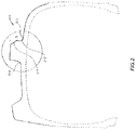
FIG. 2 shows a sectional view of the tire of FIG. 1, taken along plane A-A of this latter figure;
FIG. 3 shows an enlarged schematic representation of a lug profile taken along plane B-B of FIG. 1;
FIG. 3b shows an enlarged schematic representation of a variant lug profile with respect to that of FIG. 3;
FIG. 3c shows an enlarged schematic representation of a variant lug profile with respect to that of FIG. 3 b;
FIG. 4 shows an exemplary perspective view of a single lug of the tire of FIG. 1;
FIG. 5 shows an exemplary front view of the lug of FIG. 4;
FIG. 6 shows an exemplary perspective view of a single lug of a tire according to a second preferred embodiment of present invention;
FIG. 7 shows an enlarged schematic representation of a lug profile according to the second preferred embodiment of present invention as shown in FIG. 6, which lug profile is taken along a plane analogous to plane B-B of FIG. 1;
FIG. 8 shows an exemplary perspective view of a single lug of a tire according to a third preferred embodiment of present invention;
FIG. 9 shows an enlarged schematic view of the lug profile according to the third preferred embodiment of present invention as shown in FIG. 8, which lug profile is taken along a plane analogous to plane B-B of FIG. 1.
DETAILED DESCRIPTION OF PREFERRED EMBODIMENT OF THE INVENTION
FIG. 1 shows an agricultural tire 1 comprising a tread 10. The latter is provided with a plurality of lugs, one of which is denoted by way of example with 2. Each lug 2 protrudes from a ground 11 of tread 10 in a radially outer direction of the tire. The lugs are alternately arranged at given intervals in the circumferential direction of the tire on one side and on the other with respect to the equatorial plane of the tire.
Consistently with well-established terminology in the field, in the present context the “equatorial plane” of an agriculture tire is defined as the plane orthogonal to the rotation axis of the tires and passing through the axial middle of the tire.
More particularly—and with reference also to FIG. 4—each lug 2 extends from a first end 201 in the axial central part of the tire, i.e. in the area of the equatorial plane, towards a second end 202 in the axial lateral part of the tire, i.e. the shoulder area of the tire. The area close to, and including, the first end 201 of the lug in the central area of the tire defines a so-called nose region, or nose, 22 of the lug. The area close to, and including, the second end 202 of the lug in the shoulder area of the tire is called the shoulder region, or shoulder, 23 of the lug.
The lug extends from the nose 22 to the shoulder 23 at a given inclination angle β with respect to the circumferential direction of the tire, i.e. with respect to said tire equator plane. Generally speaking, angle β is defined as the angle between the equatorial plane and a longitudinal axis, or average longitudinal axis, G of lug 2.
Preferably, lug 2 extends from the nose 22 to the shoulder 23 along a curvature. The distance from the first end 201 the lug to the second end 202 of the lug along the curvature of the lug is called axial length of the lug and is denoted by E.
Preferably—and with reference to FIG. 5—the nose region 22 of a lug 2 is considered the region within about 33%, preferably within 25%, of the axial length E of the lug 2 from the first end 201 along its axial extension, whereas the shoulder region 23 of a lug 2 is considered the region within about 33%, preferably within 25%, of the axial length E of the lug 2 from the second end 202 along its axial extension.
Each lug 2 has a substantially trapezoidal shape when viewed in a sectional view taken, at any point, in a plane orthogonal to the path connecting the nose 22 with the shoulder 23 along the axial length E. A trapezoidal shape is shown also, for example, in FIG. 3.
The central part of the lug 2 included between ends 201 and 202 as well as between the nose region 22 and the shoulder region 23 is denoted by 27.
The rotating direction R of the tire is indicated with an arrow in FIG. 1. During rotation of the tire each lug 2 of the tread 10 sequentially comes in contact with the ground or engages the soil or mud. The first part of each lug 2 that comes in contact with the ground is the one in the central pad of the tread 10, i.e. the nose 22 of the lug 2. Upon further rotation of the tire the central part 27 of the lug 2 comes in contact with the ground. Finally, upon further rotation of the tire also the part of the lug on the axially outer side of the tread, i.e. the shoulder 23 of the lug 2, comes in contact with the ground.
The rotation direction R of the tire consequently defines one side of the lugs that first comes in contact with the mud or soil in a field, the so called stepping-in or leading side 21 of the lug 2. The opposite side of the stepping-in side 21 of the lug in circumferential direction is the so called stepping-out, or trailing, side 24 of the lug 2.
Lug 2 also includes a radially outer side 25, defining the lug surface opposite to tread ground 11 and arranged substantially orthogonal to the stepping-in side 21 and stepping-out side 24, these latter sides 21 and 24 being connected one to the other by the radially outer side 25.
Therefore, the radially outer side 25 of the lug delimits the lug in radial outer direction and intersects both the stepping in side 21 and stepping-out side 24 of the lug. The intersection of the radial cuter side 25 with the stepping-in side 21 is called the leading edge L of the lug. The intersection of the radial outer side 25 with the stepping-out side 24 is called the trailing edge T of the lug.
In the present embodiment, all lugs of the tire 1 have an improved lug profile according to a first preferred embodiment of present invention on each respective sleeping-in side 21. Such improved profile will flow be described with reference to FIGS. 2 to 4.
FIG. 2 shows a sectional view of the agricultural tire of FIG. 1 taken along the plane A-A of the latter figure. Particularly, in the detail Y, the section of lug 2 with its lug profile according to a preferred embodiment of the invention can be seen.
The external profile of the stepping-in side 21 of the lug comprises a first, radially outer, concave surface 211 and a second, radially inner, concave surface 212. The first concave surface 211 and the second concave surface 212 intersect each other at a transition point or apex, D. In a preferred embodiment as shown in FIG. 2 the first concave surface 211 intersects the radial outer side 25 of the lug at the leading edge L.
The radially inner end of the second concave surface 212 preferably terminates on the ground 11 of tire tread surface, in order to reduce the stress and strain in the transition area between the second concave surface 212 and the ground 11 of the tread 10 a first smoothening radius 213 can be added between the second concave surface 212 and the ground 11 of the tread 10.
The external profile of the stepping-out side 24 of the lug shown in FIG. 2 is flat or substantially flat. The transition between the sidewall of the stepping-out side 24 of the lug and the surface of the ground 11 of the tread 10 may be rounded with a second smoothening radius 214. The latter may be equal or different from first smoothening radius 213.
As said above, both surfaces 211 and 212 are curved, in particular concave, surfaces. Preferably, each surface 211, 212 develops, at least in each circumferential sectional plane B-B or parallel to B-B, according to a spline curve, i.e. the radius of curvature of each surface 211 and 212 varies along the radial direction.
In the present embodiment, the spline curve of first surface 211 is different from the spline curve of second surface 212.
The greatest radius of curvature of the spline curve of each surface 211 and 212 is smaller than 400 mm, preferably smaller than 350 mm and more preferably smaller than 300 mm.
Alternatively, each surface 211, 212 develops, at least in each circumferential sectional plane B-B or parallel to B-B, according a constant radius of curvature, being part of a spherical profile.
In such alternative embodiments where the radius of curvature of each surface 211 and 212 is constant, the radius of curvature of each surface 211 and 212 is smaller than 400 mm, preferably smaller than 350 mm and more preferably smaller than 300 mm.
The height H of the lug 2 is defined as the distance in radial direction of the tire from the ground 11 of the tread 10 to the radially outer 25.
As better shown FIG. 3, the transition point D is positioned at radial distance h1 from the radial outer side 25 of the lug and is positioned at a radial distance h2 from the ground 11 of the tread 10.
In this first preferred embodiment of the invention, the radial distance h1 from the transition point D to the radial outer surface 25 of the tag and the radial distance h2 between the ground 11 of the tread 10 and the transition point D are constant and do not vary along the whole axial length of the lug 2.
In this first preferred embodiment of the invention the radial distance h2 between the ground 11 of the tread 10 and the transition point D is the same as the radial distance h1 from the transition point D to the radial outer surface 25 of the lug.
As said above, in the present embodiment the radial distance h2 between the ground 11 and the transition point D is the same as the radial distance h1 from the transition point D to the radial outer surface 25 of the lug along the whole axial length E of the lug 2.
As can be seen in FIG. 3, the position on the lug profile of the transition edge D is further defined by the circumferential distance d from a reference plane P, i.e. the distance of edge D from plane P in a direction orthogonal to the lug radial height H. The plane P is the plane connecting the radially outer intersection of the first concave surface 211 with the radial outer surface of the lug 25, i.e. the leading edge L, with the radially inner intersection of the second concave surface 212 with the ground 11. In case first smoothening radius 213 is provided, plane P is the plane connecting the radially outer intersection of the first concave surface 211 with the radial outer surface 25 of the lug, i.e. the leading edge L, with the radially inner intersection of the imaginary continuation of the second concave surface 212 with the ground 11 of tread 10.
FIG. 3b is showing a variant of this preferred embodiment wherein the intersection at the leading edge L is chamfered or flattened as well as wherein a first smoothening radius 213 is provided in the transition area between the second concave surface 212 and the ground of the tread 11. In this case the plane P is the plane connecting the radially outer intersection of the imaginary continuation of the first concave surface 211 with the imaginary continuation of the radial outer surface of the lug 25, i.e. the imaginary leading edge L′, with the radially inner intersection of the imaginary continuation of the second concave surface 212 with the ground 11 of the tread 10, i.e. point O in FIG. 3 b.
With reference to FIG. 3c , when the first and the second surface are curved according to a spline, the imaginary continuation of the surfaces can be achieved in drawing a circle Ci passing through the following three point: D; the end point Ff of the respective first or second surface 211 or 212; and an intermediate third point Gf defined by the intersection of a plane Mf orthogonal to the line connecting the points D and Ff, such orthogonal plane Mf being positioned at equal distance from D and Ff.
FIG. 3c is showing by way of example the circle defined by the point D, the end point Ff the first surface 211 and the intermediate point Gf along the first surface 211.
Therefore, for the definition of the plane P it is irrelevant whether the intersection is between real surfaces or between imaginary continuations of the mentioned surfaces.
The first concave surface 211 is tangential to the plane P in the leading edge L or in the Imaginary leading edge L.
The second concave surface 212 is tangential to the plane P in the point of radially inner intersection of the second concave surface 212 with the ground 11 of the tread 10 or in the point of the radially inner intersection of the imaginary continuation of the second concave surface 212 with the ground 11 of the tread 10.
The plane P is inclined with respect to a radial plane passing through the intersection point L or L′ and orthogonal to the radial outer surface 25 of the lug at an angle α.
In a preferred embodiment of this invention the angle α is comprised in the range 0°≤α≤45°, more preferably in the range 5°≤α≤35° and even more preferably in the range 10°≤α≤≅°
According to present invention in order to achieve the best compromise between the tire performances traction, wear and sell-cleaning, the profile of the stepping-in side 21 varies along the axial length E of the lug 2 from the nose 22 to the shoulder 23.
According to present invention the distance d is not constant along the axial length E of the lug 2 from the nose 22 to the shoulder 23 of the lug.
In a preferred embodiment of this invention the distance d, along the whole axial length E of the lug 2, is comprised in the range 0×CLW≤d≤0.5 CLW, more preferably in the range 0×CLW≤d≤0.35 CLW and even more preferably in the range 0×CLW≤d≤0.25 CLW, wherein CLW is the circumferential width of the lug 2 measured at the radial outer surface 25 of the lug 2 taken in the same circumferential section as the distance d. An exemplary CLWe is shown in FIGS. 3 and 4.
In the regions of the nose 22 and the shoulder 23 the distance d is smaller than in the central area 27 of the lug 2 along the axial length of the lug 2 as shown in FIGS. 4 and 5.
According to a preferred embodiment of the invention the preferred profile distance d in the nose and shoulder region is in the range d≤0.25 dmax wherein dmax is the maximum distance d in the central area 27 of the lug 2.
The nose and shoulder regions of the lugs are the so called self-cleaning areas of the lugs. According to present invention the sidewall of the stepping-in side 21 with a reduced profile width, i.e. a small distance d in the nose region, improves the sell-cleaning in such a way that the channelling of the soil or mud in the area between the lugs is improved. The shoulder region of the lug having a reduced profile width with a small distance d improves the self-cleaning by improving the elimination of soil or mud from the tread.
Preferably the variation of the distance d along the axial length E of the lug 2 from the nose 22 to the shoulder 23 is parabolic and more preferably being zero at the end of the nose and shoulder region i.e. respectively at the first end 201 and the second end 202, of the stepping-in side 21 of the lug 2.
It is understood that other variations of the distance d along the axis of the lug are also encompassed by the present invention.
In a variant preferred embodiment of the invention the same profile disclosed for the stepping-in side 21 of lug 2 comprising the two concave surfaces 211 and 212 intersecting at the transition point D can also extend to a front sidewall of the nose 22 of the lug, as shown in FIG. 4.
A second and third preferred embodiment according to present invention comprise all the features as described in the previous first preferred embodiment with the exception of the radial position of the transition point D.
In a second and third preferred embodiment according to present invention the radial distance h2 between the ground 11 of the tread 10 and the transition point D is not the same as the radial distance h1 from the transition point D to the radial outer surface 25 of the lug 2 along the whole axial length of the lug 2. In those preferred embodiments h1 as well as h2 vary along the axial length of the lug 2.
With reference to FIGS. 6 and 7, in a second preferred embodiment of present invention in the shoulder area of the lug 2 the radial distance h2 between the ground 11 of the tread 10 and the transition point D is greater than the radial distance h1 from the transition point D to the radial outer surface 25 of the lug 2 and in the nose area 22 of the lug 2 the radial distance h2 between the ground 11 of the tread 10 and the transition point D is smaller than the radial distance h1 from the transition point D to the radially outer surface 25 of the lug 2.
As can be seen in FIG. 7, in the second preferred embodiment the radial distance h1 continuously increases along the axial length E of the lug 2 from the shoulder 23 to the nose 22 whereby the radial distance h2 consequently continuously decreases along the axial length E of the lug 2 from the shoulder 23 to the nose 22 of the lug 2.
This embodiment is particularly advantageous in field operating conditions where due to the lower inflation pressure of the agriculture tire 1 there is a higher load distribution in the shoulder areas of the agriculture tire 1 and consequently in the shoulder areas of the lugs. A reduced radial distance h1 on the shoulder, i.e. a transition point D closer to the radial outer surface 25 of the lug 2 in the shoulder area, improves the wear-resistance in the shoulder area.
According to a variant of this preferred embodiment of present invention the radial distance h2 between the ground of the tread 11 and the transition point D varies along the axial length of the lug 2 in a linear way. According to another variant of this preferred embodiment of present invention the radial distance h2 between the ground of the tread 11 and the transition point D varies along the axial length of the lug in a non-linear way, preferably curved or parabolic way.
With reference to FIGS. 8 and 9, in a third preferred embodiment according to present invention, in the shoulder region 23 the radial distance h2 between the ground 11 of the tread 10 and the transition point D is smaller than the radial distance h1 from the transition point D to the radial eater surface 25 of the lug 2 and in the nose region the radial distance h2 between the ground 11 of the tread 10 and the transition point D is greater than the distance h1 from the transition point D to the radially outer surface 25 of the lug 2.
As can be seen in FIG. D, in the third preferred embodiment the radial distance h1 continuously decreases along the axial length E of the lug from the shoulder to the nose whereby the radial distance h2 consequently continuously increases along the axial length E of the lug from the shoulder to the nose area.
This embodiment is particularly advantageous in road operating conditions where due to the higher inflation pressure of the agriculture tire 1 there is a higher load distribution in the central area of the agriculture tire 1 and consequently of the nose region of the lugs. A reduced radial distance h1 in the nose area, i.e. a transition point D closer to the radially outer surface 25 of the lug 2 in the nose area improves the wear resistance in the central area of the fire.
According to a variant of this preferred embodiment of present invention the racial distance h2 between the ground of the tread 11 and the transition point D varies along the axial length E of the lug 2 in a linear way. According to another variant of this preferred embodiment of present invention the radial distance h2 between the ground 11 of the tread 10 and the transition point D varies along the axial length E of the lug 2 in a non-linear way, preferably curved or parabolic way.
Transition point D can also be implemented as a thin region instead that as a single point. In particular, a junction profile can be applied between the first and the second concave surface. For example, a circular junction may be present, having, in a sectional view like that of FIG. 2, a radius of curvature comprised in a range of about 0.5-1.0 mm. Also in this case, reference may be made to a transition point, meant to indicate also a thin transition region as just defined.
It is understood that the single embodiments can simultaneously be implemented on a single agriculture tire 1 by alternating them on different lugs. The a trend 10 for agriculture tire 1 might comprise a plurality of lugs wherein the plurality of lugs might comprise different groups of plurality of lugs each group according to different embodiments of present invention alternately arranged on the tread. The same agricultural tire 1 might further comprise also standard lugs known in the art.
The present invention has been described so far with reference to preferred embodiments. It is intended that there may be other embodiments which refer to the same inventive concept and fail within the scope of the following claims.

Claims (20)

The invention claimed is:
1. A tread (10) for an agricultural tire (1), comprising a plurality of lugs protruding from a ground (11) of the tread (10) in a radially outer direction,
each lug (2) comprising a stepping-in surface (21) and a radially-outer surface (25),
wherein the stepping-in surface (21) of at least one lug (2) comprises a first, radially outer, concave curved surface (211) and a second, radially inner, concave curved surface (212) intersecting each other in a transition point (D),
wherein the transition point (D) is positioned at a circumferential distance (d) from a reference plane (P) connecting a radially outer intersection (L, L′) of the first concave curved surface (211) with the radially outer surface (25) and a radially inner intersection (O) of the second concave curved surface (212) with the ground (11),
characterized in that the circumferential distance (d) of said at least one lug (2) varies along an axial length (E) of the lug (2).
2. The tread (10) of claim 1, wherein the circumferential distance (d) in a central part (27) of said at least one lug (2) is greater than the circumferential distance (d) in a shoulder region (23) of the lug (2) and in a nose region (22) of the lug (2).
3. The tread (10) of claim 2, wherein the circumferential distance (d) in the shoulder region (23) and in the nose region (22) is ≤25% of the maximum circumferential distance (dmax) in the central part (27) of the lug (2).
4. The tread (10) according to claim 1, wherein the circumferential distance (d) is comprised in the range 0×CLW≤d≤0.5 CLW, wherein CLW is the circumferential width of said at least one lug (2) measured at the radial outer surface (25) and taken in the same circumferential section as the circumferential distance (d).
5. The tread (10) of claim 1, wherein the variation of the circumferential distance (d) along the axial length (E) from a shoulder region (23) to a nose region (22) of said at least one lug (2) is parabolic, preferably being zero at the end of the shoulder and/or nose region.
6. The tread (10) according to claim 1, wherein said reference plane (P) is inclined with respect to a radial plane passing through the intersection point (L, L′) of the first concave curved surface (211) with the radially outer surface (25) and orthogonal to the radially outer surface (25) at an angle (α), wherein this latter angle (α) is comprised in the range 0°≤α≤45°.
7. The tread (10) of claim 1, comprising at least one lug (2) wherein a first radial distance (h1) from the transition point (D) to the radial outer surface of the lug (25) and a second radial distance (h2) from the ground of the tread (11) and the transition point (D) are constant and do not vary along the whole axial length (E) of the lug (2).
8. The tread (10) of claim 7, wherein the second radial distance (h2) is the same as the first radial distance (h1).
9. The tread (10) of claim 1, wherein said first concave curved surface (211) and said second concave curved surface (212) extend onto a front sidewall of a nose region (22) of said at least one lug (2).
10. The tread (10) of claim 1, comprising at least one lug (2) wherein a second radial distance (h2) from the ground of the tread (11) to the transition point (D) varies along the axial length (E) of the lug (2).
11. The tread (10) of claim 10, wherein in a shoulder region (23) of said at least one lug (2) the second radial distance (h2) is greater than a first radial distance (h1) from the transition point (D) to the radially outer surface (25) of the lug (2) and in a nose region (22) of the lug (2) the second radial distance (h2) is smaller than the first radial distance (h1).
12. The tread (10) of claim 10, wherein in a shoulder region (23) of said at least one lug (2) the second radial distance (h2) is smaller than a first radial distance (h1) from the transition point (D) to the radially outer surface (25) of the lug (2) and in a nose region (22) of the lug (2) the second radial distance (h2) is greater than the first radial distance (h1).
13. The tread (10) of claim 10, wherein the second radial distance (h2) between the ground of the tread (11) and the transition point (D) varies in a linear way along the axial length (E) of the lug (2).
14. The tread (10) of claim 10, wherein the second radial distance (h2) between the ground of the tread (11) and the transition point (D) varies in a non-linear way along the axial length (E) of the lug (2).
15. An agriculture tire (1) comprising the tread (10) of claim 1.
16. The tread according to claim 4, wherein the circumferential distance (d) is comprised in the range 0×CLW≤d≤0.35.
17. The tread according to claim 16, wherein the circumferential distance (d) is comprised in the range 0×CLW≤d≤0.25 CLW.
18. The tread (10) according to claim 6, wherein the latter angle (α) is comprised in the range 0°≤α≤45°.
19. The tread (10) according to claim 18, wherein the latter angle (α) is comprised in the range 10°≤α≤25°.
20. The tread (10) according to claim 14, wherein the second radial distance (h2) between the ground of the tread (11) and the transition point (D) varies in a parabolic way along the axial length (E) of the lug (2).
US15/766,025 2015-10-29 2016-10-20 Agricultural tire Active 2037-08-31 US10906357B2 (en)

Applications Claiming Priority (3)

Application Number Priority Date Filing Date Title
ITUB2015A005089A ITUB20155089A1 (en) 2015-10-29 2015-10-29 AGRICULTURAL TIRE
IT102015000066713 2015-10-29
PCT/EP2016/075180 WO2017072014A1 (en) 2015-10-29 2016-10-20 Agricultural tire

Publications (2)

Publication Number Publication Date
US20180297415A1 US20180297415A1 (en) 2018-10-18
US10906357B2 true US10906357B2 (en) 2021-02-02

Family

ID=55273400

Family Applications (1)

Application Number Title Priority Date Filing Date
US15/766,025 Active 2037-08-31 US10906357B2 (en) 2015-10-29 2016-10-20 Agricultural tire

Country Status (6)

Country Link
US (1) US10906357B2 (en)
EP (1) EP3368347B1 (en)
CN (1) CN108349317B (en)
BR (1) BR112018006521B1 (en)
IT (1) ITUB20155089A1 (en)
WO (1) WO2017072014A1 (en)

Cited By (3)

* Cited by examiner, † Cited by third party
Publication number Priority date Publication date Assignee Title
USD958056S1 (en) * 2020-06-18 2022-07-19 Nokian Heavy Tyres Ltd Tire
USD967001S1 (en) * 2020-06-18 2022-10-18 Nokian Heavy Tyres Ltd Tire
USD967002S1 (en) * 2020-06-18 2022-10-18 Nokian Heavy Tyres Ltd Tire

Families Citing this family (2)

* Cited by examiner, † Cited by third party
Publication number Priority date Publication date Assignee Title
US11572115B2 (en) 2019-07-17 2023-02-07 Srj, Inc. Tread pattern
DE202020100216U1 (en) 2019-11-08 2020-07-17 Apollo Tyres Global R&D B.V. Agricultural machine tires

Citations (5)

* Cited by examiner, † Cited by third party
Publication number Priority date Publication date Assignee Title
JPS60145902U (en) 1984-03-09 1985-09-27 株式会社ブリヂストン stepped lug tires
JPH09254609A (en) 1996-03-26 1997-09-30 Ohtsu Tire & Rubber Co Ltd :The Pneumatic tire with lug
JP2008018751A (en) 2006-07-10 2008-01-31 Sumitomo Rubber Ind Ltd Traveling body with lug
US20140196823A1 (en) * 2011-05-25 2014-07-17 Michelin Recherche Et Tecnique S.A. Tire tread for a farm tractor
WO2015015525A1 (en) 2013-07-30 2015-02-05 Trelleborg Wheel Systems Italia S.P.A. Tire with improved traction

Family Cites Families (4)

* Cited by examiner, † Cited by third party
Publication number Priority date Publication date Assignee Title
JP5676202B2 (en) * 2010-10-04 2015-02-25 株式会社ブリヂストン Agricultural tires
EP2658732B1 (en) * 2010-12-29 2019-04-03 Pirelli Tyre S.p.A. Agricultural tyre
CN202685791U (en) * 2012-06-08 2013-01-23 厦门正新橡胶工业有限公司 Agricultural tire
JP5833197B2 (en) * 2014-07-14 2015-12-16 株式会社ブリヂストン Agricultural tires

Patent Citations (6)

* Cited by examiner, † Cited by third party
Publication number Priority date Publication date Assignee Title
JPS60145902U (en) 1984-03-09 1985-09-27 株式会社ブリヂストン stepped lug tires
JPH09254609A (en) 1996-03-26 1997-09-30 Ohtsu Tire & Rubber Co Ltd :The Pneumatic tire with lug
JP2008018751A (en) 2006-07-10 2008-01-31 Sumitomo Rubber Ind Ltd Traveling body with lug
US20140196823A1 (en) * 2011-05-25 2014-07-17 Michelin Recherche Et Tecnique S.A. Tire tread for a farm tractor
WO2015015525A1 (en) 2013-07-30 2015-02-05 Trelleborg Wheel Systems Italia S.P.A. Tire with improved traction
US20160193882A1 (en) * 2013-07-30 2016-07-07 Trelleborg Wheel Systems Italia S.P.A. Tire with improved traction

Non-Patent Citations (2)

* Cited by examiner, † Cited by third party
Title
International Search Report of PCT/EP2016/075180 dated Jan. 30, 2017.
Written Opinion of the International Searching Authority of PCT/EP2016/075180 dated Jan. 30, 2017.

Cited By (4)

* Cited by examiner, † Cited by third party
Publication number Priority date Publication date Assignee Title
USD958056S1 (en) * 2020-06-18 2022-07-19 Nokian Heavy Tyres Ltd Tire
USD967001S1 (en) * 2020-06-18 2022-10-18 Nokian Heavy Tyres Ltd Tire
USD967003S1 (en) * 2020-06-18 2022-10-18 Nokian Heavy Tyres Ltd Tire
USD967002S1 (en) * 2020-06-18 2022-10-18 Nokian Heavy Tyres Ltd Tire

Also Published As

Publication number Publication date
BR112018006521A2 (en) 2018-10-16
EP3368347B1 (en) 2020-01-15
CN108349317A (en) 2018-07-31
WO2017072014A1 (en) 2017-05-04
EP3368347A1 (en) 2018-09-05
CN108349317B (en) 2020-07-14
BR112018006521B1 (en) 2021-08-24
US20180297415A1 (en) 2018-10-18
ITUB20155089A1 (en) 2017-04-29

Similar Documents

Publication Publication Date Title
US10906357B2 (en) Agricultural tire
CN111347826B (en) Tyre for vehicle wheels
JP5922364B2 (en) Reinforced tire tread
EP2546075B1 (en) Tread for a pneumatic tire
US4446902A (en) Tires for drive wheels of agricultural tractors or similar vehicles
US4383567A (en) Pneumatic tractor tire
US20080149237A1 (en) Pneumatic tire
EP1987965B1 (en) Pneumatic tire
EP1935670B1 (en) Pneumatic tire
US20160159162A1 (en) Pneumatic tire for use on row-crop field sprayers and other like farm machinery
KR20130086975A (en) Pneumatic tire
US20080271826A1 (en) Pnuematic tire
US11820176B2 (en) Tyre for agricultural machine
US11167599B2 (en) Tire for motorcycle for uneven ground traveling
US20190315161A1 (en) Tyre for vehicle wheels
CN108472999B (en) Tire treads for agricultural vehicles
US20210237515A1 (en) Tread for an Agricultural Vehicle
US10300746B2 (en) Pneumatic tire
CN104812594B (en) Tire tread with orthotype design
US20210138838A1 (en) Agricultural Vehicle Tire
EP0116997A2 (en) A pneumatic aircraft tire
US12304249B2 (en) Tread for an agricultural vehicle
EP4570524A1 (en) Pneumatic tire and tire mold
EP4570523A1 (en) Pneumatic tire
CN112867613A (en) Pneumatic tire for vehicle

Legal Events

Date Code Title Description
AS Assignment

Owner name: BRIDGESTONE CORPORATION, JAPAN

Free format text: ASSIGNMENT OF ASSIGNORS INTEREST;ASSIGNORS:SGRECCIA, MARIO;TEDESCO, ADRIANO;PERETTI, FABRIZIO;SIGNING DATES FROM 20180320 TO 20180403;REEL/FRAME:045446/0704

FEPP Fee payment procedure

Free format text: ENTITY STATUS SET TO UNDISCOUNTED (ORIGINAL EVENT CODE: BIG.); ENTITY STATUS OF PATENT OWNER: LARGE ENTITY

STPP Information on status: patent application and granting procedure in general

Free format text: DOCKETED NEW CASE - READY FOR EXAMINATION

STPP Information on status: patent application and granting procedure in general

Free format text: NON FINAL ACTION MAILED

STPP Information on status: patent application and granting procedure in general

Free format text: RESPONSE TO NON-FINAL OFFICE ACTION ENTERED AND FORWARDED TO EXAMINER

STPP Information on status: patent application and granting procedure in general

Free format text: RESPONSE AFTER FINAL ACTION FORWARDED TO EXAMINER

STPP Information on status: patent application and granting procedure in general

Free format text: PUBLICATIONS -- ISSUE FEE PAYMENT RECEIVED

STCF Information on status: patent grant

Free format text: PATENTED CASE

MAFP Maintenance fee payment

Free format text: PAYMENT OF MAINTENANCE FEE, 4TH YEAR, LARGE ENTITY (ORIGINAL EVENT CODE: M1551); ENTITY STATUS OF PATENT OWNER: LARGE ENTITY

Year of fee payment: 4