US10903637B2 - Structures for securing broadcast cabling and connectors - Google Patents
Structures for securing broadcast cabling and connectors Download PDFInfo
- Publication number
- US10903637B2 US10903637B2 US16/700,630 US201916700630A US10903637B2 US 10903637 B2 US10903637 B2 US 10903637B2 US 201916700630 A US201916700630 A US 201916700630A US 10903637 B2 US10903637 B2 US 10903637B2
- Authority
- US
- United States
- Prior art keywords
- cavity
- panel
- section
- connectors
- lock system
- Prior art date
- Legal status (The legal status is an assumption and is not a legal conclusion. Google has not performed a legal analysis and makes no representation as to the accuracy of the status listed.)
- Active
Links
- 238000002955 isolation Methods 0.000 claims abstract description 15
- 238000005192 partition Methods 0.000 claims description 16
- 239000000463 material Substances 0.000 claims description 4
- 239000000835 fiber Substances 0.000 description 4
- 230000007246 mechanism Effects 0.000 description 2
- 239000002184 metal Substances 0.000 description 2
- 238000009434 installation Methods 0.000 description 1
Images


Classifications
-
- H—ELECTRICITY
- H02—GENERATION; CONVERSION OR DISTRIBUTION OF ELECTRIC POWER
- H02G—INSTALLATION OF ELECTRIC CABLES OR LINES, OR OF COMBINED OPTICAL AND ELECTRIC CABLES OR LINES
- H02G3/00—Installations of electric cables or lines or protective tubing therefor in or on buildings, equivalent structures or vehicles
- H02G3/02—Details
- H02G3/08—Distribution boxes; Connection or junction boxes
- H02G3/081—Bases, casings or covers
-
- A—HUMAN NECESSITIES
- A47—FURNITURE; DOMESTIC ARTICLES OR APPLIANCES; COFFEE MILLS; SPICE MILLS; SUCTION CLEANERS IN GENERAL
- A47B—TABLES; DESKS; OFFICE FURNITURE; CABINETS; DRAWERS; GENERAL DETAILS OF FURNITURE
- A47B53/00—Cabinets or racks having several sections one behind the other
-
- A—HUMAN NECESSITIES
- A47—FURNITURE; DOMESTIC ARTICLES OR APPLIANCES; COFFEE MILLS; SPICE MILLS; SUCTION CLEANERS IN GENERAL
- A47F—SPECIAL FURNITURE, FITTINGS, OR ACCESSORIES FOR SHOPS, STOREHOUSES, BARS, RESTAURANTS OR THE LIKE; PAYING COUNTERS
- A47F3/00—Show cases or show cabinets
- A47F3/002—Devices for protection against sunlight or theft
-
- E—FIXED CONSTRUCTIONS
- E05—LOCKS; KEYS; WINDOW OR DOOR FITTINGS; SAFES
- E05B—LOCKS; ACCESSORIES THEREFOR; HANDCUFFS
- E05B65/00—Locks or fastenings for special use
- E05B65/0003—Locks or fastenings for special use for locking a plurality of wings, e.g. simultaneously
-
- G—PHYSICS
- G02—OPTICS
- G02B—OPTICAL ELEMENTS, SYSTEMS OR APPARATUS
- G02B6/00—Light guides; Structural details of arrangements comprising light guides and other optical elements, e.g. couplings
- G02B6/44—Mechanical structures for providing tensile strength and external protection for fibres, e.g. optical transmission cables
- G02B6/4439—Auxiliary devices
- G02B6/444—Systems or boxes with surplus lengths
- G02B6/4452—Distribution frames
- G02B6/44526—Panels or rackmounts covering a whole width of the frame or rack
-
- H—ELECTRICITY
- H02—GENERATION; CONVERSION OR DISTRIBUTION OF ELECTRIC POWER
- H02G—INSTALLATION OF ELECTRIC CABLES OR LINES, OR OF COMBINED OPTICAL AND ELECTRIC CABLES OR LINES
- H02G3/00—Installations of electric cables or lines or protective tubing therefor in or on buildings, equivalent structures or vehicles
- H02G3/02—Details
- H02G3/08—Distribution boxes; Connection or junction boxes
- H02G3/10—Distribution boxes; Connection or junction boxes for surface mounting on a wall
-
- H—ELECTRICITY
- H02—GENERATION; CONVERSION OR DISTRIBUTION OF ELECTRIC POWER
- H02G—INSTALLATION OF ELECTRIC CABLES OR LINES, OR OF COMBINED OPTICAL AND ELECTRIC CABLES OR LINES
- H02G3/00—Installations of electric cables or lines or protective tubing therefor in or on buildings, equivalent structures or vehicles
- H02G3/02—Details
- H02G3/08—Distribution boxes; Connection or junction boxes
- H02G3/16—Distribution boxes; Connection or junction boxes structurally associated with support for line-connecting terminals within the box
-
- A—HUMAN NECESSITIES
- A47—FURNITURE; DOMESTIC ARTICLES OR APPLIANCES; COFFEE MILLS; SPICE MILLS; SUCTION CLEANERS IN GENERAL
- A47B—TABLES; DESKS; OFFICE FURNITURE; CABINETS; DRAWERS; GENERAL DETAILS OF FURNITURE
- A47B97/00—Furniture or accessories for furniture, not provided for in other groups of this subclass
- A47B2097/003—Cable holders; cable organisers
-
- G—PHYSICS
- G02—OPTICS
- G02B—OPTICAL ELEMENTS, SYSTEMS OR APPARATUS
- G02B6/00—Light guides; Structural details of arrangements comprising light guides and other optical elements, e.g. couplings
- G02B6/44—Mechanical structures for providing tensile strength and external protection for fibres, e.g. optical transmission cables
- G02B6/4439—Auxiliary devices
- G02B6/444—Systems or boxes with surplus lengths
- G02B6/44528—Patch-cords; Connector arrangements in the system or in the box
-
- H—ELECTRICITY
- H02—GENERATION; CONVERSION OR DISTRIBUTION OF ELECTRIC POWER
- H02G—INSTALLATION OF ELECTRIC CABLES OR LINES, OR OF COMBINED OPTICAL AND ELECTRIC CABLES OR LINES
- H02G3/00—Installations of electric cables or lines or protective tubing therefor in or on buildings, equivalent structures or vehicles
- H02G3/02—Details
- H02G3/08—Distribution boxes; Connection or junction boxes
- H02G3/081—Bases, casings or covers
- H02G3/083—Inlets
-
- H—ELECTRICITY
- H02—GENERATION; CONVERSION OR DISTRIBUTION OF ELECTRIC POWER
- H02G—INSTALLATION OF ELECTRIC CABLES OR LINES, OR OF COMBINED OPTICAL AND ELECTRIC CABLES OR LINES
- H02G3/00—Installations of electric cables or lines or protective tubing therefor in or on buildings, equivalent structures or vehicles
- H02G3/02—Details
- H02G3/08—Distribution boxes; Connection or junction boxes
- H02G3/14—Fastening of cover or lid to box
Definitions
- This invention relates to broadcast connectivity and, more particularly, a system of structures for securing broadcast cabling and connectors.
- the broadcast market utilizes unique cables and connectors.
- the specific types of cable and connectors chosen for a particular network is related to the network's topology, protocol, and size. This invention details the development of multiple panels, enclosures, and brackets that cater to the broadcast market.
- a structure for securing broadcast cables and connectors including a wall mounted enclosure including a front section, a middle section and rear section, the front and middle sections surrounding a first cavity and the middle and rear sections surrounding a second cavity, and wherein a partition separates the first and second cavities; a panel having a first wing and a second wing, the panel defining a plurality of isolation plate mounts on the first wing, the panel being sized and configured for engaged abutment with the partition, and wherein the first and the second wings join together to form a convex angle; the panel being selectively interchangeable between first and second configurations, wherein the first configuration is defined by the panel being selectively attached to the partition such that the convex angle formed by the first and the second wings faces the first cavity and the second configuration is defined by the panel being selectively attached to the partition such that the convex angle formed by the first and the second wings faces the second cavity; an internal lock system for selectively accessing the second cavity, where
- a structure for securing broadcast cables and connectors including a wall mounted enclosure including a front section, a middle section and rear section, the front and middle sections surrounding a first cavity and the middle and rear sections surrounding a second cavity, and wherein a partition separates the first and second cavities; a panel having a first wing and a second wing, the panel defining a plurality of isolation plate mounts on the first wing, the panel being sized and configured for engaged abutment with the partition, and wherein the first and the second wings join together to form a convex angle; an internal lock system for selectively accessing the second cavity, wherein the internal lock system is structured and disposed to lock the middle section to the rear section; the internal lock system being accessible from within the first cavity; and at least one cable management bracket in the second cavity of the wall mounted enclosure.
- a structure for securing broadcast cables and connectors including a wall mounted enclosure including a front section, a middle section and rear section, the front and middle sections surrounding a first cavity and the middle and rear sections surrounding a second cavity, and wherein a partition separates the first and second cavities; a panel having a first wing and a second wing, the panel defining a plurality of isolation plate mounts on the first wing, the panel being sized and configured for engaged abutment with the partition, and wherein the first and the second wings join together to form a convex angle; an internal lock system for selectively accessing the second cavity, wherein the internal lock system is structured and disposed to lock the middle section to the rear section; and at least one cable management bracket in the second cavity of the wall mounted enclosure.
- FIG. 1 is a perspective view of a rack mounted panel with eight isolation plate mounts and being made from one metal piece with no welds or other fastening mechanisms;
- FIG. 2 is a perspective view of a 2 u rack mounted enclosure with removable cover and eight universal isolation plate mounts on the rear and an open front that can accommodate an angled adapter plate;
- FIG. 3 is a perspective view of an open rack mount enclosure with cable management brackets
- FIG. 4 is a perspective view of a rack mount enclosure with angle panel in front, wherein the enclosure attaches directly to the rack and the panel is attached to the rack on top of the enclosure;
- FIG. 5 is a perspective view of a closed rack mount enclosure with angle panel in alternate orientation
- FIG. 6 is a perspective view of a rugged throw-down box with universal isolation plate mounts and including a recessed lid to protect fiber connectors and handle cutouts cut through both cover and base of enclosure;
- FIG. 7 is a perspective view of an interior bracket that is welded onto side of chassis. It is the base on to which the cover fastens. It incorporates a novel fiber management system on the edges of the bracket;
- FIG. 8 is a perspective view of a wall mount enclosure in the fully closed configuration
- FIG. 9 is a perspective view of a wall mount enclosure in the fully closed configuration
- FIG. 10 is a perspective view of a wall mount enclosure with the front section and middle section in the opened configuration
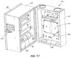
- FIG. 11 is a perspective view of a wall mount enclosure with the middle section and rear section in the opened configuration
- FIG. 12 is a perspective view of a wall mount enclosure with the middle section and rear section in the opened configuration.
- FIG. 13 is a perspective view of a wall mount enclosure in the fully opened configuration.
- FIG. 4-5 the system of structures for securing broadcast cabling and connectors of the present invention is shown and described herein and is generally indicated as 10 , a fully assembled rack mount enclosure 16 with attachment of a rack mounted panel 12 in alternate orientation, as shown in FIG. 4-5 .
- a rack mounted panel 12 has two wings forming a convex angle and includes eight universal isolation plate mounts 14 A on one wing.
- the rack mounted panel 12 is made from one metal piece with no welds or other fastening mechanisms. Other suitable materials may be used to form the rack mounted panel 12 .
- the 2 u rack mounted enclosure 16 includes a removable cover 18 and eight universal isolation plate mounts 14 B on the rear, as well as an open front that can accommodate the rack mounted panel 12 .
- an opened 2 u rack mount enclosure base 20 is shown without the removable cover 18 or the attachable rack mount panel 12 .
- On the inner bottom surface there is at least one cable management brackets 22 for managing cable.
- FIG. 4 a fully assembled 2 u rack mount enclosure 10 including the rack mounted panel 12 is shown, wherein the rack mounted panel 12 is attached to the front side of the 2 u rack mount enclosure 16 .
- the rack mounted panel 12 is attached in an orientation that the convex angle of two wings of the rack mounted panel 12 is facing inside.
- a fully assembled 2 u rack mount enclosure 10 may include the rack mounted panel 12 in an alternate orientation that the convex angle of two wings of the rack mounted panel 12 is facing outside. Importantly, orientations of the rack mounted panel 12 can be changed without removing the 2 u rack mount enclosure 16 .
- a rugged throw-down box 24 includes a number of universal isolation plate mounts 14 and a recessed lid 26 for protecting fiber connectors 28 .
- Two handle cutouts 30 are cut through two side surfaces of the rugged throw-down box 24 .
- an interior bracket 32 is welded onto the inner side surface of the rugged throw-down box 24 , below the handle cutout 30 . It is the base on to which a cover fastens, thereby forming the recessed lid 26 .
- the interior bracket 32 includes a slotted fiber management system 34 along its opposing edges.
- the angle between two wings of the rack mounted panel 12 is between 30° and 90°.
- the universal isolation plate mounts 14 A may be on the top section (as shown in FIG. 5 ) or the bottom section (as shown in FIG. 4 ) of the front side of the 2 u rack mounted enclosure 16 , as is required by the environment.
- FIGS. 8-13 another embodiment of the system of structures for securing broadcast cabling and connectors is shown and includes a wall mount enclosure 116 for use in controlled environment broadcast locations, such as studios, sports locker rooms, corporate facilities, stadium broadcast booths, schools and/or houses of worship in a single enclosure requiring no additional equipment.
- controlled environment broadcast locations such as studios, sports locker rooms, corporate facilities, stadium broadcast booths, schools and/or houses of worship in a single enclosure requiring no additional equipment.
- the wall mount enclosure 116 includes three sections (front section 118 , middle section 120 and rear section 122 ) for ease of installation.
- the front section 118 is hingedly securable to the middle section 120 and the middle section 120 is hingedly securable to the rear section 122 .
- the front section 118 and middle section 120 form a first cavity 124 and the middle section 120 and rear section 122 form a second cavity 126 .
- a lock system 128 is provided on the outer surface of the wall mount enclosure 116 for selectively locking the front section 118 and middle section 120 in the closed configuration.
- the lock system 128 may be a latch lock that is used in connection with a padlock (not shown).
- An internal lock system 130 is provided for selectively locking the middle section 120 with the rear section 122 in the closed configuration such that access to the second cavity 126 is tamper resistant when the front section 118 is secured to the middle section 120 .
- the internal locking system 130 includes an internal locking screw 132 on the middle section 120 that is sized and configured for engaging an opening 134 formed by a clasp member 136 in the second cavity 126 , which is secured to the rear section 122 , when the middle section 120 is closed against the rear section 122 , and wherein the internal locking screw 132 is accessible from within the first cavity 124 .
- a panel 138 having a first wing 140 and a second wing 142 and defining a plurality of isolation plate mounts 144 is provided to reduce heavy cable load on connectors. It is preferred that the angle between two wings 140 and 142 of the panel 138 is between 30° and 90°.
- the wall mount enclosure 116 provides adaptability to multiple connector types, including but not limited to SMPTE, BNC, RJ45, SC, ST, LC, and FC.
- the rear section 122 incorporates conduit openings and the center section 120 includes rubber grommets 146 for cable entry/exit.
Landscapes
- Engineering & Computer Science (AREA)
- Architecture (AREA)
- Civil Engineering (AREA)
- Structural Engineering (AREA)
- Physics & Mathematics (AREA)
- General Physics & Mathematics (AREA)
- Optics & Photonics (AREA)
- Installation Of Indoor Wiring (AREA)
Abstract
Description
Claims (14)
Priority Applications (1)
| Application Number | Priority Date | Filing Date | Title |
|---|---|---|---|
| US16/700,630 US10903637B2 (en) | 2016-09-09 | 2019-12-02 | Structures for securing broadcast cabling and connectors |
Applications Claiming Priority (3)
| Application Number | Priority Date | Filing Date | Title |
|---|---|---|---|
| US201662385490P | 2016-09-09 | 2016-09-09 | |
| US15/700,944 US10498119B2 (en) | 2016-09-09 | 2017-09-11 | Structures for securing broadcast cabling and connectors |
| US16/700,630 US10903637B2 (en) | 2016-09-09 | 2019-12-02 | Structures for securing broadcast cabling and connectors |
Related Parent Applications (1)
| Application Number | Title | Priority Date | Filing Date |
|---|---|---|---|
| US15/700,944 Continuation-In-Part US10498119B2 (en) | 2016-09-09 | 2017-09-11 | Structures for securing broadcast cabling and connectors |
Publications (2)
| Publication Number | Publication Date |
|---|---|
| US20200106252A1 US20200106252A1 (en) | 2020-04-02 |
| US10903637B2 true US10903637B2 (en) | 2021-01-26 |
Family
ID=69946652
Family Applications (1)
| Application Number | Title | Priority Date | Filing Date |
|---|---|---|---|
| US16/700,630 Active US10903637B2 (en) | 2016-09-09 | 2019-12-02 | Structures for securing broadcast cabling and connectors |
Country Status (1)
| Country | Link |
|---|---|
| US (1) | US10903637B2 (en) |
Cited By (2)
| Publication number | Priority date | Publication date | Assignee | Title |
|---|---|---|---|---|
| US12221810B2 (en) | 2021-07-09 | 2025-02-11 | Hoffman Enclosures Inc. | Apparatus and methods for securing an equipment cabinet |
| US12512653B1 (en) * | 2024-08-05 | 2025-12-30 | Wangs Alliance Corporation | Junction box |
Families Citing this family (1)
| Publication number | Priority date | Publication date | Assignee | Title |
|---|---|---|---|---|
| US10903637B2 (en) * | 2016-09-09 | 2021-01-26 | Optical Cable Corporation | Structures for securing broadcast cabling and connectors |
Citations (91)
| Publication number | Priority date | Publication date | Assignee | Title |
|---|---|---|---|---|
| US241123A (en) * | 1881-05-10 | Revolving book | ||
| US850210A (en) * | 1904-12-19 | 1907-04-16 | Robert J Cady | Cabinet for music-spools. |
| US1227799A (en) * | 1915-09-20 | 1917-05-29 | Arthur D Kaub | Cabinet. |
| US1254132A (en) * | 1916-09-19 | 1918-01-22 | Adrian St Clair Garman | Medicine-cabinet. |
| US1440146A (en) * | 1922-02-14 | 1922-12-26 | Eugene W Hawley | Locking device for trunk drawers |
| US1779218A (en) * | 1928-02-23 | 1930-10-21 | Schmalzgruber Sebastian | Cabinet |
| US2086472A (en) * | 1936-08-10 | 1937-07-06 | Mccaskey Register Co | Filing appliance |
| US2213274A (en) * | 1937-10-07 | 1940-09-03 | Alexander L Flamm | Refrigerator |
| US2286427A (en) * | 1941-02-11 | 1942-06-16 | Harry L Levensten | Box or chest for tools |
| US2311718A (en) * | 1941-08-11 | 1943-02-23 | Elwood J Way | Receptacle for cards and providing a compartment for the personal use of operators |
| US2414752A (en) * | 1943-01-25 | 1947-01-21 | Judson D Mabie | Wall support with pivoted racks |
| US2660506A (en) * | 1950-02-24 | 1953-11-24 | Wright Elvin Stanley | Storage file for program tapes |
| US2739024A (en) * | 1953-02-20 | 1956-03-20 | Elman Jerome | Storage cabinet construction |
| US3055723A (en) * | 1960-10-31 | 1962-09-25 | Continental Baking Co | Combination transporting and display rack |
| US3089745A (en) * | 1960-12-27 | 1963-05-14 | Louis J Postula | Cabinet with multiple vertically mounted separate shelving members |
| US3310905A (en) * | 1966-01-03 | 1967-03-28 | Roger E Davis | Fishing tackle box |
| US4211455A (en) * | 1979-05-21 | 1980-07-08 | Tedrow Joe E | Tool box accessory cabinet |
| US4303158A (en) * | 1979-09-24 | 1981-12-01 | Perkins Donald R | Tool box |
| US4343172A (en) * | 1978-09-19 | 1982-08-10 | Svenor Modul-System Ab | Tool holders and a method of their manufacture |
| US4502742A (en) * | 1983-01-05 | 1985-03-05 | Neff Paul J | Storage unit |
| US4586633A (en) * | 1983-04-07 | 1986-05-06 | Coin Acceptors, Inc. | Vending machine storage rack assembly |
| US4648737A (en) * | 1985-06-24 | 1987-03-10 | Burroughs Corporation | Theft prevention apparatus |
| US4675782A (en) * | 1985-12-20 | 1987-06-23 | General Electric Company | Molded plastic enclosure for disconnect switches |
| US4892198A (en) * | 1987-10-21 | 1990-01-09 | Johnson Barry T | Article display apparatus |
| US5267710A (en) * | 1992-09-25 | 1993-12-07 | Condon Duane R | Pipe hanging clamp adapted for soldering |
| US5422436A (en) * | 1992-03-07 | 1995-06-06 | Rittal-Werk Rudolf Loh Gmbh & Co. | Control cabinet |
| US5615850A (en) * | 1995-03-06 | 1997-04-01 | Cloninger; Leonard W. | Wire support bracket |
| US5641079A (en) * | 1995-06-09 | 1997-06-24 | Great Neck Saw Manufacturers, Inc. | Tool holder |
| US5769006A (en) * | 1993-10-06 | 1998-06-23 | Alcadi | Safety box |
| US5820238A (en) * | 1997-05-20 | 1998-10-13 | Sauder Woodworking Co. | Cabinet |
| US5945633A (en) * | 1996-05-23 | 1999-08-31 | The Siemon Company | Rack mountable cable distribution enclosure having an angled adapter plate bracket |
| US5971329A (en) * | 1996-11-20 | 1999-10-26 | 3244 Corporation | Conduit support |
| US6242697B1 (en) * | 1999-05-28 | 2001-06-05 | General Electric Company | Molded plastic enclosure |
| US6269961B1 (en) * | 2000-01-14 | 2001-08-07 | M. Kamenstein, Inc. | Foldable support rack |
| US6305388B1 (en) * | 1999-10-22 | 2001-10-23 | Richard D. Zeller | Portable hair salon station |
| US20020181896A1 (en) * | 2001-06-04 | 2002-12-05 | Mcclellan Brian J. | Telecommunications chassis and module |
| US6591952B1 (en) * | 2002-04-18 | 2003-07-15 | Donna M. Randall | Cosmetic appliance storage and cord management apparatus |
| US6737576B1 (en) * | 2003-05-16 | 2004-05-18 | Thomas & Betts International, Inc. | Electrical box assembly |
| US6806425B1 (en) * | 2003-06-27 | 2004-10-19 | Lucasey Manufacturing Co. | Appliance mounting apparatus |
| US6866541B2 (en) * | 2001-07-26 | 2005-03-15 | Panduit Corp. | Angled patch panel with cable support bar for network cable racks |
| US6884942B2 (en) * | 2000-03-28 | 2005-04-26 | Panduit Corp. | Cable manager for network rack |
| US6959821B2 (en) * | 2000-12-13 | 2005-11-01 | Hannstar Display Corp. | Display detecting apparatus for display module and detecting arrangement method therefor |
| US20060032990A1 (en) * | 2004-08-11 | 2006-02-16 | Cask John A | Rack and duct system |
| US20060060114A1 (en) * | 2000-11-30 | 2006-03-23 | Walker James T | Security safe |
| US20060118321A1 (en) * | 2004-12-03 | 2006-06-08 | Hubbell Incorporated. | Cable management system with patch panel |
| US7098406B1 (en) * | 2005-03-11 | 2006-08-29 | Jack Hammonds | Cord, cable and tubing organizer |
| US7249681B2 (en) * | 2004-02-13 | 2007-07-31 | Trade Guys International Pty Ltd. | Media shelving |
| US20070196071A1 (en) * | 2005-09-09 | 2007-08-23 | Leviton Manufacturing Co., Inc. | Patch panel |
| US7479598B1 (en) * | 2006-06-16 | 2009-01-20 | Taymac Corporation | Electrical device cover |
| US20090067800A1 (en) * | 2007-09-07 | 2009-03-12 | Mariano Perez Vazquez | Fiber optic adapter module and tray |
| US7520474B1 (en) * | 2006-04-28 | 2009-04-21 | Sioux Chief Mfg. Co., Inc. | Cantilevered pipe support bracket |
| US20090163043A1 (en) * | 2007-12-21 | 2009-06-25 | Yannick Demers | Patch panel with angled module |
| US7637773B2 (en) * | 2007-01-24 | 2009-12-29 | Rit Technologies Ltd. | Patch panel with a variable angle |
| US20090321371A1 (en) * | 2008-04-30 | 2009-12-31 | Jason Rathbone | Modular rack system |
| US7726750B2 (en) * | 2006-06-30 | 2010-06-01 | Hoffman Enclosures, Inc. | Latch for enclosure |
| US7866909B2 (en) * | 2008-01-11 | 2011-01-11 | Marvin Albert Denmark | Cable locking system |
| US7905454B2 (en) * | 2003-06-23 | 2011-03-15 | Thermal Dynamics Corporation | Metal tube support bracket |
| US8038015B2 (en) * | 2006-09-08 | 2011-10-18 | Leviton Manufacturing Co., Ltd. | Equipment rack panel system and method |
| US8054649B2 (en) * | 2009-10-01 | 2011-11-08 | Etherwan Systems, Inc. | Adjustable housing frame with industrial rails for adjusting the depth of communication apparatus within a housing cabinet |
| US8119915B2 (en) * | 2007-10-05 | 2012-02-21 | Leviton Manufacturing Co., Inc. | Cable management patch panel system with vertical ducting |
| US20120193309A1 (en) * | 2011-01-31 | 2012-08-02 | Fleischer Donald M | Flexible mounting system for electronic devices |
| US8246382B1 (en) * | 2011-06-16 | 2012-08-21 | Yfc-Boneagle Electric Co., Ltd. | Bendable patch panel structure |
| US20120288249A1 (en) * | 2011-05-13 | 2012-11-15 | Gil Ruiz | Pivotable cover for sliding tray and sliding tray including the cover |
| US8360373B2 (en) * | 2009-09-17 | 2013-01-29 | Target Brands, Inc. | Display apparatus and method |
| US20130134116A1 (en) * | 2008-09-05 | 2013-05-30 | Adc Gmbh | Frame with cable management |
| US8456819B1 (en) * | 2009-03-30 | 2013-06-04 | Brian Delynn Smith | Personal storage device with charging capability |
| US8522969B2 (en) * | 2011-08-11 | 2013-09-03 | Cathy Mason | Appliance storage and organizer device |
| US8544623B1 (en) * | 2011-09-23 | 2013-10-01 | Ramon R. Murphy | Cord organizing system for hair shears |
| US8695929B2 (en) * | 2011-02-16 | 2014-04-15 | Martin Cox | Vertical cable support structures and methods |
| US8752848B2 (en) * | 2010-06-17 | 2014-06-17 | Bretford Manufacturing, Inc. | Computer cart |
| US20140206273A1 (en) * | 2007-11-19 | 2014-07-24 | Ortronics, Inc. | Equipment Rack and Associated Ventilation System |
| US8834199B2 (en) * | 2011-04-11 | 2014-09-16 | Hsing Chau Industrial Co., Ltd. | Tilted module for assembling network distribution device |
| US20140366390A1 (en) * | 2013-06-18 | 2014-12-18 | Justin Lampley | Organizational Device |
| US8931742B2 (en) * | 2012-06-29 | 2015-01-13 | ScienBiziP Consulting (Shen Zhen) Co., Ltd. | Cable management apparatus |
| US9192231B1 (en) * | 2014-02-12 | 2015-11-24 | Daniel W. Steffen | Curio cabinet with concealed gun rack |
| US9247319B2 (en) * | 2013-06-17 | 2016-01-26 | Cisco Technology, Inc. | Panel assembly |
| US9383179B1 (en) * | 2015-05-07 | 2016-07-05 | Patrick Spilotro | Firearm magazine storage rack with adjustable partitions |
| US9532638B2 (en) * | 2014-04-08 | 2017-01-03 | Michael L. Davis | Apparatus for retaining a plurality of hair care devices |
| US9632271B2 (en) * | 2014-06-17 | 2017-04-25 | Ortronics, Inc. | Modularly mountable cable management systems and associated methods |
| US9660397B2 (en) * | 2014-03-24 | 2017-05-23 | Commscope Technologies Llc | Plate for cable connector attachments |
| US20170187205A1 (en) * | 2015-12-23 | 2017-06-29 | Aver Information Inc. | Charge cabinet and storage device thereof |
| US9914209B2 (en) * | 2009-06-16 | 2018-03-13 | Larry Mitchell Grela | Tool box storage assembly |
| US20180076604A1 (en) * | 2016-09-09 | 2018-03-15 | Optical Cable Corporation | Structures for Securing Broadcast Cabling and Connectors |
| US9924611B2 (en) * | 2015-05-15 | 2018-03-20 | Innovation First, Inc. | Connectors to secure multiple rails in a server rack |
| US9938012B1 (en) * | 2013-11-25 | 2018-04-10 | Michael C. Kollias | Collapsible article organizer for airliner use |
| US9943177B1 (en) * | 2017-05-09 | 2018-04-17 | Creative Display Works, Inc. | Display and storage cabinet and related methods |
| US9952397B2 (en) * | 2014-09-23 | 2018-04-24 | Ppc Broadband Inc. | Universal multi-purpose compartmentalized telecommunications box |
| US10135268B1 (en) * | 2016-03-15 | 2018-11-20 | Digilock Asia Ltd. | Lockers with charging power |
| US20190281978A1 (en) * | 2018-03-14 | 2019-09-19 | Power Systems (Ps), Llc | Fitness equipment storage system |
| US20200036175A1 (en) * | 2018-07-27 | 2020-01-30 | Primex Manufacturing Ltd. | Device mounting apparatus, kits, methods, and systems |
| US20200106252A1 (en) * | 2016-09-09 | 2020-04-02 | Optical Cable Corporation | Structures for Securing Broadcast Cabling and Connectors |
-
2019
- 2019-12-02 US US16/700,630 patent/US10903637B2/en active Active
Patent Citations (91)
| Publication number | Priority date | Publication date | Assignee | Title |
|---|---|---|---|---|
| US241123A (en) * | 1881-05-10 | Revolving book | ||
| US850210A (en) * | 1904-12-19 | 1907-04-16 | Robert J Cady | Cabinet for music-spools. |
| US1227799A (en) * | 1915-09-20 | 1917-05-29 | Arthur D Kaub | Cabinet. |
| US1254132A (en) * | 1916-09-19 | 1918-01-22 | Adrian St Clair Garman | Medicine-cabinet. |
| US1440146A (en) * | 1922-02-14 | 1922-12-26 | Eugene W Hawley | Locking device for trunk drawers |
| US1779218A (en) * | 1928-02-23 | 1930-10-21 | Schmalzgruber Sebastian | Cabinet |
| US2086472A (en) * | 1936-08-10 | 1937-07-06 | Mccaskey Register Co | Filing appliance |
| US2213274A (en) * | 1937-10-07 | 1940-09-03 | Alexander L Flamm | Refrigerator |
| US2286427A (en) * | 1941-02-11 | 1942-06-16 | Harry L Levensten | Box or chest for tools |
| US2311718A (en) * | 1941-08-11 | 1943-02-23 | Elwood J Way | Receptacle for cards and providing a compartment for the personal use of operators |
| US2414752A (en) * | 1943-01-25 | 1947-01-21 | Judson D Mabie | Wall support with pivoted racks |
| US2660506A (en) * | 1950-02-24 | 1953-11-24 | Wright Elvin Stanley | Storage file for program tapes |
| US2739024A (en) * | 1953-02-20 | 1956-03-20 | Elman Jerome | Storage cabinet construction |
| US3055723A (en) * | 1960-10-31 | 1962-09-25 | Continental Baking Co | Combination transporting and display rack |
| US3089745A (en) * | 1960-12-27 | 1963-05-14 | Louis J Postula | Cabinet with multiple vertically mounted separate shelving members |
| US3310905A (en) * | 1966-01-03 | 1967-03-28 | Roger E Davis | Fishing tackle box |
| US4343172A (en) * | 1978-09-19 | 1982-08-10 | Svenor Modul-System Ab | Tool holders and a method of their manufacture |
| US4211455A (en) * | 1979-05-21 | 1980-07-08 | Tedrow Joe E | Tool box accessory cabinet |
| US4303158A (en) * | 1979-09-24 | 1981-12-01 | Perkins Donald R | Tool box |
| US4502742A (en) * | 1983-01-05 | 1985-03-05 | Neff Paul J | Storage unit |
| US4586633A (en) * | 1983-04-07 | 1986-05-06 | Coin Acceptors, Inc. | Vending machine storage rack assembly |
| US4648737A (en) * | 1985-06-24 | 1987-03-10 | Burroughs Corporation | Theft prevention apparatus |
| US4675782A (en) * | 1985-12-20 | 1987-06-23 | General Electric Company | Molded plastic enclosure for disconnect switches |
| US4892198A (en) * | 1987-10-21 | 1990-01-09 | Johnson Barry T | Article display apparatus |
| US5422436A (en) * | 1992-03-07 | 1995-06-06 | Rittal-Werk Rudolf Loh Gmbh & Co. | Control cabinet |
| US5267710A (en) * | 1992-09-25 | 1993-12-07 | Condon Duane R | Pipe hanging clamp adapted for soldering |
| US5769006A (en) * | 1993-10-06 | 1998-06-23 | Alcadi | Safety box |
| US5615850A (en) * | 1995-03-06 | 1997-04-01 | Cloninger; Leonard W. | Wire support bracket |
| US5641079A (en) * | 1995-06-09 | 1997-06-24 | Great Neck Saw Manufacturers, Inc. | Tool holder |
| US5945633A (en) * | 1996-05-23 | 1999-08-31 | The Siemon Company | Rack mountable cable distribution enclosure having an angled adapter plate bracket |
| US5971329A (en) * | 1996-11-20 | 1999-10-26 | 3244 Corporation | Conduit support |
| US5820238A (en) * | 1997-05-20 | 1998-10-13 | Sauder Woodworking Co. | Cabinet |
| US6242697B1 (en) * | 1999-05-28 | 2001-06-05 | General Electric Company | Molded plastic enclosure |
| US6305388B1 (en) * | 1999-10-22 | 2001-10-23 | Richard D. Zeller | Portable hair salon station |
| US6269961B1 (en) * | 2000-01-14 | 2001-08-07 | M. Kamenstein, Inc. | Foldable support rack |
| US6884942B2 (en) * | 2000-03-28 | 2005-04-26 | Panduit Corp. | Cable manager for network rack |
| US20060060114A1 (en) * | 2000-11-30 | 2006-03-23 | Walker James T | Security safe |
| US6959821B2 (en) * | 2000-12-13 | 2005-11-01 | Hannstar Display Corp. | Display detecting apparatus for display module and detecting arrangement method therefor |
| US20020181896A1 (en) * | 2001-06-04 | 2002-12-05 | Mcclellan Brian J. | Telecommunications chassis and module |
| US6866541B2 (en) * | 2001-07-26 | 2005-03-15 | Panduit Corp. | Angled patch panel with cable support bar for network cable racks |
| US6591952B1 (en) * | 2002-04-18 | 2003-07-15 | Donna M. Randall | Cosmetic appliance storage and cord management apparatus |
| US6737576B1 (en) * | 2003-05-16 | 2004-05-18 | Thomas & Betts International, Inc. | Electrical box assembly |
| US7905454B2 (en) * | 2003-06-23 | 2011-03-15 | Thermal Dynamics Corporation | Metal tube support bracket |
| US6806425B1 (en) * | 2003-06-27 | 2004-10-19 | Lucasey Manufacturing Co. | Appliance mounting apparatus |
| US7249681B2 (en) * | 2004-02-13 | 2007-07-31 | Trade Guys International Pty Ltd. | Media shelving |
| US20060032990A1 (en) * | 2004-08-11 | 2006-02-16 | Cask John A | Rack and duct system |
| US20060118321A1 (en) * | 2004-12-03 | 2006-06-08 | Hubbell Incorporated. | Cable management system with patch panel |
| US7098406B1 (en) * | 2005-03-11 | 2006-08-29 | Jack Hammonds | Cord, cable and tubing organizer |
| US20070196071A1 (en) * | 2005-09-09 | 2007-08-23 | Leviton Manufacturing Co., Inc. | Patch panel |
| US7520474B1 (en) * | 2006-04-28 | 2009-04-21 | Sioux Chief Mfg. Co., Inc. | Cantilevered pipe support bracket |
| US7479598B1 (en) * | 2006-06-16 | 2009-01-20 | Taymac Corporation | Electrical device cover |
| US7726750B2 (en) * | 2006-06-30 | 2010-06-01 | Hoffman Enclosures, Inc. | Latch for enclosure |
| US8038015B2 (en) * | 2006-09-08 | 2011-10-18 | Leviton Manufacturing Co., Ltd. | Equipment rack panel system and method |
| US7637773B2 (en) * | 2007-01-24 | 2009-12-29 | Rit Technologies Ltd. | Patch panel with a variable angle |
| US20090067800A1 (en) * | 2007-09-07 | 2009-03-12 | Mariano Perez Vazquez | Fiber optic adapter module and tray |
| US8119915B2 (en) * | 2007-10-05 | 2012-02-21 | Leviton Manufacturing Co., Inc. | Cable management patch panel system with vertical ducting |
| US20140206273A1 (en) * | 2007-11-19 | 2014-07-24 | Ortronics, Inc. | Equipment Rack and Associated Ventilation System |
| US20090163043A1 (en) * | 2007-12-21 | 2009-06-25 | Yannick Demers | Patch panel with angled module |
| US7866909B2 (en) * | 2008-01-11 | 2011-01-11 | Marvin Albert Denmark | Cable locking system |
| US20090321371A1 (en) * | 2008-04-30 | 2009-12-31 | Jason Rathbone | Modular rack system |
| US20130134116A1 (en) * | 2008-09-05 | 2013-05-30 | Adc Gmbh | Frame with cable management |
| US8456819B1 (en) * | 2009-03-30 | 2013-06-04 | Brian Delynn Smith | Personal storage device with charging capability |
| US9914209B2 (en) * | 2009-06-16 | 2018-03-13 | Larry Mitchell Grela | Tool box storage assembly |
| US8360373B2 (en) * | 2009-09-17 | 2013-01-29 | Target Brands, Inc. | Display apparatus and method |
| US8054649B2 (en) * | 2009-10-01 | 2011-11-08 | Etherwan Systems, Inc. | Adjustable housing frame with industrial rails for adjusting the depth of communication apparatus within a housing cabinet |
| US8752848B2 (en) * | 2010-06-17 | 2014-06-17 | Bretford Manufacturing, Inc. | Computer cart |
| US20120193309A1 (en) * | 2011-01-31 | 2012-08-02 | Fleischer Donald M | Flexible mounting system for electronic devices |
| US8695929B2 (en) * | 2011-02-16 | 2014-04-15 | Martin Cox | Vertical cable support structures and methods |
| US8834199B2 (en) * | 2011-04-11 | 2014-09-16 | Hsing Chau Industrial Co., Ltd. | Tilted module for assembling network distribution device |
| US20120288249A1 (en) * | 2011-05-13 | 2012-11-15 | Gil Ruiz | Pivotable cover for sliding tray and sliding tray including the cover |
| US8246382B1 (en) * | 2011-06-16 | 2012-08-21 | Yfc-Boneagle Electric Co., Ltd. | Bendable patch panel structure |
| US8522969B2 (en) * | 2011-08-11 | 2013-09-03 | Cathy Mason | Appliance storage and organizer device |
| US8544623B1 (en) * | 2011-09-23 | 2013-10-01 | Ramon R. Murphy | Cord organizing system for hair shears |
| US8931742B2 (en) * | 2012-06-29 | 2015-01-13 | ScienBiziP Consulting (Shen Zhen) Co., Ltd. | Cable management apparatus |
| US9247319B2 (en) * | 2013-06-17 | 2016-01-26 | Cisco Technology, Inc. | Panel assembly |
| US20140366390A1 (en) * | 2013-06-18 | 2014-12-18 | Justin Lampley | Organizational Device |
| US9938012B1 (en) * | 2013-11-25 | 2018-04-10 | Michael C. Kollias | Collapsible article organizer for airliner use |
| US9192231B1 (en) * | 2014-02-12 | 2015-11-24 | Daniel W. Steffen | Curio cabinet with concealed gun rack |
| US9660397B2 (en) * | 2014-03-24 | 2017-05-23 | Commscope Technologies Llc | Plate for cable connector attachments |
| US9532638B2 (en) * | 2014-04-08 | 2017-01-03 | Michael L. Davis | Apparatus for retaining a plurality of hair care devices |
| US9632271B2 (en) * | 2014-06-17 | 2017-04-25 | Ortronics, Inc. | Modularly mountable cable management systems and associated methods |
| US9952397B2 (en) * | 2014-09-23 | 2018-04-24 | Ppc Broadband Inc. | Universal multi-purpose compartmentalized telecommunications box |
| US9383179B1 (en) * | 2015-05-07 | 2016-07-05 | Patrick Spilotro | Firearm magazine storage rack with adjustable partitions |
| US9924611B2 (en) * | 2015-05-15 | 2018-03-20 | Innovation First, Inc. | Connectors to secure multiple rails in a server rack |
| US20170187205A1 (en) * | 2015-12-23 | 2017-06-29 | Aver Information Inc. | Charge cabinet and storage device thereof |
| US10135268B1 (en) * | 2016-03-15 | 2018-11-20 | Digilock Asia Ltd. | Lockers with charging power |
| US20180076604A1 (en) * | 2016-09-09 | 2018-03-15 | Optical Cable Corporation | Structures for Securing Broadcast Cabling and Connectors |
| US20200106252A1 (en) * | 2016-09-09 | 2020-04-02 | Optical Cable Corporation | Structures for Securing Broadcast Cabling and Connectors |
| US9943177B1 (en) * | 2017-05-09 | 2018-04-17 | Creative Display Works, Inc. | Display and storage cabinet and related methods |
| US20190281978A1 (en) * | 2018-03-14 | 2019-09-19 | Power Systems (Ps), Llc | Fitness equipment storage system |
| US20200036175A1 (en) * | 2018-07-27 | 2020-01-30 | Primex Manufacturing Ltd. | Device mounting apparatus, kits, methods, and systems |
Cited By (2)
| Publication number | Priority date | Publication date | Assignee | Title |
|---|---|---|---|---|
| US12221810B2 (en) | 2021-07-09 | 2025-02-11 | Hoffman Enclosures Inc. | Apparatus and methods for securing an equipment cabinet |
| US12512653B1 (en) * | 2024-08-05 | 2025-12-30 | Wangs Alliance Corporation | Junction box |
Also Published As
| Publication number | Publication date |
|---|---|
| US20200106252A1 (en) | 2020-04-02 |
Similar Documents
| Publication | Publication Date | Title |
|---|---|---|
| US10903637B2 (en) | Structures for securing broadcast cabling and connectors | |
| US10498119B2 (en) | Structures for securing broadcast cabling and connectors | |
| US20150346450A1 (en) | Pivotably attachable fiber optic housing, modular housing system and method | |
| CA2756296C (en) | Fiber splice enclosure | |
| US10433031B1 (en) | Stackable wall mount enclosure | |
| US8093496B2 (en) | Cable management system for moveable communication panels | |
| US6603660B1 (en) | Remote distribution frame | |
| US7307213B1 (en) | Horizontal electrical box with internal mounting arrangement | |
| US10375346B2 (en) | Component rack for a display | |
| CN110485599A (en) | Wall panels, wall panel systems, frames for wall panels and methods of assembling wall panel systems | |
| CN112020902A (en) | Telecommunications chassis with modular locking system | |
| US6914772B2 (en) | Video conference system enclosure | |
| CN112805894B (en) | Recessed floor fitting and cover therefor | |
| US5984720A (en) | Angled interconnect panel assembly for telecommunications applications | |
| CA2588040C (en) | Secure cable system | |
| US6060660A (en) | Consolidation point enclosure | |
| US20090238530A1 (en) | Universal fiber distribution hub | |
| WO2007126459A2 (en) | Permanent terminations of network cables | |
| CA2721773A1 (en) | Locking mechanisms for retaining two swinging panels and apparatus and enclosures including a locking mechanism for retaining two swinging panels | |
| US20010015764A1 (en) | Container for television cameras of closed-circuit monitoring and surveillance systems with protection of the connectors of the connecting cables | |
| WO2021096548A1 (en) | Electronics enclosure device | |
| US20260118615A1 (en) | Gangable fiber optic distribution box and scalable box system | |
| US20170346268A1 (en) | Protective skirt for telecommunications lines | |
| GB2441797A (en) | Cable joint housing for distribution cabinet |
Legal Events
| Date | Code | Title | Description |
|---|---|---|---|
| FEPP | Fee payment procedure |
Free format text: ENTITY STATUS SET TO UNDISCOUNTED (ORIGINAL EVENT CODE: BIG.); ENTITY STATUS OF PATENT OWNER: SMALL ENTITY |
|
| FEPP | Fee payment procedure |
Free format text: ENTITY STATUS SET TO SMALL (ORIGINAL EVENT CODE: SMAL); ENTITY STATUS OF PATENT OWNER: SMALL ENTITY |
|
| STPP | Information on status: patent application and granting procedure in general |
Free format text: DOCKETED NEW CASE - READY FOR EXAMINATION |
|
| STPP | Information on status: patent application and granting procedure in general |
Free format text: NON FINAL ACTION MAILED |
|
| STPP | Information on status: patent application and granting procedure in general |
Free format text: RESPONSE TO NON-FINAL OFFICE ACTION ENTERED AND FORWARDED TO EXAMINER |
|
| STPP | Information on status: patent application and granting procedure in general |
Free format text: NOTICE OF ALLOWANCE MAILED -- APPLICATION RECEIVED IN OFFICE OF PUBLICATIONS |
|
| AS | Assignment |
Owner name: OPTICAL CABLE CORPORATION, VIRGINIA Free format text: ASSIGNMENT OF ASSIGNORS INTEREST;ASSIGNORS:NEHLS, CHARLIE;TIMMINS, IAN J.;SIGNING DATES FROM 20200218 TO 20201019;REEL/FRAME:054666/0243 |
|
| STPP | Information on status: patent application and granting procedure in general |
Free format text: PUBLICATIONS -- ISSUE FEE PAYMENT VERIFIED |
|
| STCF | Information on status: patent grant |
Free format text: PATENTED CASE |
|
| MAFP | Maintenance fee payment |
Free format text: PAYMENT OF MAINTENANCE FEE, 4TH YR, SMALL ENTITY (ORIGINAL EVENT CODE: M2551); ENTITY STATUS OF PATENT OWNER: SMALL ENTITY Year of fee payment: 4 |