US10894641B2 - Adhesively closed packaging systems - Google Patents
Adhesively closed packaging systems Download PDFInfo
- Publication number
- US10894641B2 US10894641B2 US16/138,225 US201816138225A US10894641B2 US 10894641 B2 US10894641 B2 US 10894641B2 US 201816138225 A US201816138225 A US 201816138225A US 10894641 B2 US10894641 B2 US 10894641B2
- Authority
- US
- United States
- Prior art keywords
- lid
- adhesive
- base
- well
- packaging system
- Prior art date
- Legal status (The legal status is an assumption and is not a legal conclusion. Google has not performed a legal analysis and makes no representation as to the accuracy of the status listed.)
- Expired - Fee Related, expires
Links
Images


Classifications
-
- B—PERFORMING OPERATIONS; TRANSPORTING
- B65—CONVEYING; PACKING; STORING; HANDLING THIN OR FILAMENTARY MATERIAL
- B65D—CONTAINERS FOR STORAGE OR TRANSPORT OF ARTICLES OR MATERIALS, e.g. BAGS, BARRELS, BOTTLES, BOXES, CANS, CARTONS, CRATES, DRUMS, JARS, TANKS, HOPPERS, FORWARDING CONTAINERS; ACCESSORIES, CLOSURES, OR FITTINGS THEREFOR; PACKAGING ELEMENTS; PACKAGES
- B65D53/00—Sealing or packing elements; Sealings formed by liquid or plastics material
- B65D53/06—Sealings formed by liquid or plastic material
-
- A—HUMAN NECESSITIES
- A45—HAND OR TRAVELLING ARTICLES
- A45D—HAIRDRESSING OR SHAVING EQUIPMENT; EQUIPMENT FOR COSMETICS OR COSMETIC TREATMENTS, e.g. FOR MANICURING OR PEDICURING
- A45D33/00—Containers or accessories specially adapted for handling powdery toiletry or cosmetic substances
-
- A—HUMAN NECESSITIES
- A45—HAND OR TRAVELLING ARTICLES
- A45D—HAIRDRESSING OR SHAVING EQUIPMENT; EQUIPMENT FOR COSMETICS OR COSMETIC TREATMENTS, e.g. FOR MANICURING OR PEDICURING
- A45D34/00—Containers or accessories specially adapted for handling liquid toiletry or cosmetic substances, e.g. perfumes
-
- B—PERFORMING OPERATIONS; TRANSPORTING
- B65—CONVEYING; PACKING; STORING; HANDLING THIN OR FILAMENTARY MATERIAL
- B65B—MACHINES, APPARATUS OR DEVICES FOR, OR METHODS OF, PACKAGING ARTICLES OR MATERIALS; UNPACKING
- B65B7/00—Closing containers or receptacles after filling
- B65B7/16—Closing semi-rigid or rigid containers or receptacles not deformed by, or not taking-up shape of, contents, e.g. boxes or cartons
- B65B7/26—Closing semi-rigid or rigid containers or receptacles not deformed by, or not taking-up shape of, contents, e.g. boxes or cartons by closing hinged lids
-
- B—PERFORMING OPERATIONS; TRANSPORTING
- B65—CONVEYING; PACKING; STORING; HANDLING THIN OR FILAMENTARY MATERIAL
- B65D—CONTAINERS FOR STORAGE OR TRANSPORT OF ARTICLES OR MATERIALS, e.g. BAGS, BARRELS, BOTTLES, BOXES, CANS, CARTONS, CRATES, DRUMS, JARS, TANKS, HOPPERS, FORWARDING CONTAINERS; ACCESSORIES, CLOSURES, OR FITTINGS THEREFOR; PACKAGING ELEMENTS; PACKAGES
- B65D43/00—Lids or covers for rigid or semi-rigid containers
- B65D43/02—Removable lids or covers
- B65D43/0202—Removable lids or covers without integral tamper element
- B65D43/0204—Removable lids or covers without integral tamper element secured by snapping over beads or projections
- B65D43/0212—Removable lids or covers without integral tamper element secured by snapping over beads or projections only on the outside, or a part turned to the outside, of the mouth
-
- B—PERFORMING OPERATIONS; TRANSPORTING
- B65—CONVEYING; PACKING; STORING; HANDLING THIN OR FILAMENTARY MATERIAL
- B65D—CONTAINERS FOR STORAGE OR TRANSPORT OF ARTICLES OR MATERIALS, e.g. BAGS, BARRELS, BOTTLES, BOXES, CANS, CARTONS, CRATES, DRUMS, JARS, TANKS, HOPPERS, FORWARDING CONTAINERS; ACCESSORIES, CLOSURES, OR FITTINGS THEREFOR; PACKAGING ELEMENTS; PACKAGES
- B65D47/00—Closures with filling and discharging, or with discharging, devices
- B65D47/04—Closures with discharging devices other than pumps
- B65D47/06—Closures with discharging devices other than pumps with pouring spouts or tubes; with discharge nozzles or passages
- B65D47/08—Closures with discharging devices other than pumps with pouring spouts or tubes; with discharge nozzles or passages having articulated or hinged closures
- B65D47/0804—Closures with discharging devices other than pumps with pouring spouts or tubes; with discharge nozzles or passages having articulated or hinged closures integrally formed with the base element provided with the spout or discharge passage
- B65D47/0833—Hinges without elastic bias
- B65D47/0838—Hinges without elastic bias located at an edge of the base element
-
- B—PERFORMING OPERATIONS; TRANSPORTING
- B65—CONVEYING; PACKING; STORING; HANDLING THIN OR FILAMENTARY MATERIAL
- B65D—CONTAINERS FOR STORAGE OR TRANSPORT OF ARTICLES OR MATERIALS, e.g. BAGS, BARRELS, BOTTLES, BOXES, CANS, CARTONS, CRATES, DRUMS, JARS, TANKS, HOPPERS, FORWARDING CONTAINERS; ACCESSORIES, CLOSURES, OR FITTINGS THEREFOR; PACKAGING ELEMENTS; PACKAGES
- B65D55/00—Accessories for container closures not otherwise provided for
- B65D55/02—Locking devices; Means for discouraging or indicating unauthorised opening or removal of closure
-
- B—PERFORMING OPERATIONS; TRANSPORTING
- B65—CONVEYING; PACKING; STORING; HANDLING THIN OR FILAMENTARY MATERIAL
- B65D—CONTAINERS FOR STORAGE OR TRANSPORT OF ARTICLES OR MATERIALS, e.g. BAGS, BARRELS, BOTTLES, BOXES, CANS, CARTONS, CRATES, DRUMS, JARS, TANKS, HOPPERS, FORWARDING CONTAINERS; ACCESSORIES, CLOSURES, OR FITTINGS THEREFOR; PACKAGING ELEMENTS; PACKAGES
- B65D2251/00—Details relating to container closures
- B65D2251/10—Details of hinged closures
- B65D2251/1016—Means for locking the closure in closed position
- B65D2251/1025—Integral locking elements penetrating in an opening, e.g. a flap through a slit, a hook in an opening
Definitions
- Representative packaging systems generally include a base, a lid, a closure structure, and an adhesive deposit.
- the base has a well.
- the lid is hingeably connected to the base and has a user input region and a protrusion projecting into the well.
- the closure structure is configured for releasably retaining the lid in a closed position relative to the base.
- the adhesive deposit is located within the well and at least partially surrounds the protrusion, and forms a first plurality of adhesive bonds with the well and a second plurality of adhesive bonds with the protrusion.
- the second plurality of adhesive bonds and the closure structure are configured to exert a combined retention force of at least 20N.
- the closure structure alone may be configured to exert a retention force of at least 10N.
- the closure structure may include part of a hinge, wherein the second plurality of adhesive bonds is offset from the user input region by less than 10.0 mm in between the user input region and the hinge.
- the first plurality of adhesive bonds may cover a first surface area of the well and the second plurality of adhesive bonds may cover a second surface area of the lid that is 50 mm 2 to 150 mm 2 . In one aspect, the first surface area may be greater than the second surface area.
- a ratio of the first surface area to the second surface area is 2.0 to 10.0.
- the adhesive deposit contains less than or equal to 0.3 g of adhesive.
- the adhesive deposit contains less than or equal to 0.5 ml of adhesive.
- At least one of the first plurality of adhesive bonds is formed at a surface having a first roughness
- at least one of the second plurality of adhesive bonds is formed at a surface having a second roughness, the first roughness being greater than the second roughness
- the closure structure is part of at least one of the base and the lid.
- the second plurality of adhesive bonds is configured to permanently retain the adhesive deposit within the well.
- the well is open on a bottom side. In one aspect, an upper wall of the base obstructs the adhesive deposit from being removed from the well.
- the packaging system may include a container that attaches to the base.
- the packaging system may include a second protrusion opening that opens into a second well, and a second protrusion projecting through the second protrusion opening and into the second well.
- the protrusion and the second protrusion are located on opposite sides of the user input region.
- the packaging system may include a tray configured to fit within the base, wherein the base, tray, and the lid together substantially form a makeup compact.
- One representative method generally includes providing a base and a lid hingeably connected to the base, the lid having a protrusion and a user input region, the base having a well configured to receive at least part of the protrusion, applying an adhesive deposit into the well, closing the lid relative to the base such that at least part of the protrusion extends into the well, and allowing the adhesive deposit to dry.
- closing the lid may occur prior to applying the adhesive deposit into the well.
- the method may include turning the base upside down prior to applying the adhesive deposit.
- applying the adhesive deposit may include applying a drop of adhesive through an open bottom of the well.
- FIG. 1 is a perspective view of a representative system according to the present disclosure, including a representative example of a base and a representative example of a lid.
- FIG. 2 is a top view of the base and lid of FIG. 1 .
- FIG. 3 is a perspective section view of the base and lid of FIG. 1 , showing the lid in an open position.
- FIG. 4 is a front section view of the base and lid of FIG. 1 , showing the lid in an open position.
- FIG. 5 is a side view of the base and lid of FIG. 1 , showing the lid in a closed position.
- FIG. 6 is a side section view of the base and lid of FIG. 1 , showing the lid in a closed position.
- FIG. 7 is another front section view of the base and lid of FIG. 1 , showing the lid in a closed position.
- FIG. 8 is a lower perspective view of the base and lid of FIG. 1 , showing a bottom side.
- FIG. 9 is a perspective view of another representative system according to the present disclosure, including a representative example of a base and a representative example of a lid.
- FIG. 10 is a section view of the base and lid of FIG. 9 , showing the lid in a closed position.
- FIG. 11 is a front section view of the base and lid of FIG. 9 .
- FIG. 12 is a perspective view of the base of FIG. 9 .
- FIG. 13 is a side section view of the base and lid of FIG. 9 .
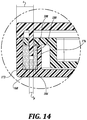
- FIG. 14 is a partial side section view of the base and lid of FIG. 9 .
- the present disclosure provides examples of containers, caps, and other closeable containers that are optimized for e-commerce fulfillment, resist tampering, and provide evidence of tampering.
- the problem solved by the inventive solutions arises from more frequent and greater forces exerted on bottles, makeup compacts, and other closable containers in e-commerce distribution channels as compared to traditional retail distribution channels.
- closable containers purchased via traditional retail distribution channels where an end user typically transports a closable container (e.g., a shampoo bottle) from the location of sale to the location of use
- closable containers purchased via the internet often undergo additional fulfillment, shipping, and other handling steps prior to reaching the end user.
- closable containers can experience forces that may cause container failure (for example, a lid may inadvertently open, spilling product), and/or may experience tampering. Higher container failure rates contribute to increased costs, customer dissatisfaction, waste, and inconvenience.
- the present disclosure provides packaging systems that include one or more adhesively-closed lids, such as may be assembled and/or otherwise provided with one or more of a wide variety of packaging, including caps, bases, and/or containers (including bottles, tubs, wells, tubes, vessels, and the like).
- a wide variety of liquid and solid products may benefit from such lids, such as shampoo, soaps, lotions, medications, cosmetic formulations (including powdered formulations), pharmaceutical formulations, and other formulations.
- the present disclosure is not intended to be limited to any particular application(s) or formulation.
- a representative packaging system 10 includes a container 14 and a cap 16 .
- the cap includes a base 20 and a lid 24 .
- the container 14 is a bottle, such as may be suitable for holding a product 12 , e.g., shampoo, conditioner, body wash, lotion, etc.
- the container may be formed by the base and the lid, such as a container to hold a tray for storing dry cosmetic formulations and an applicator. Some embodiments may not include a container.
- the container and cap may be manufactured from one or more of a wide variety of materials, including ABS, polypropylene, polystyrene, polyethylene, polyurethane, polyvinylchloride, polybutylene terephthalate, polyester, other plastics, wood-based materials, and metals.
- the base 20 and the lid 24 of FIG. 1 are manufactured from copolymer polypropylene.
- FIGS. 1-4 show the lid 24 in an open position
- FIGS. 5-8 show the lid 24 in the closed position.
- the term “open position” refers to any position of the lid 24 relative to the base 20 in which a space between the base 20 and the lid 24 may be accessed, or any position in which contents contained within the container 14 may: be dispensed; pour out; fall out; blow out; escape; be accessed by a user; otherwise exit the packaging system 10 .
- closed position refers to any non-open position of the lid 24 relative to the base 20 in which 1) the lid 24 makes contact with the base 20 and in which a space between the base 20 and the lid 24 may not be accessed, or 2) any contents contained within the container 14 cannot: be dispensed; pour out; fall out; blow out; escape; be accessed by a user; or otherwise exit the packaging system 10 .
- this application refers to a singular “open position” and singular “closed position,” there could potentially be more than one open position and closed position.
- the base 20 and lid 24 are an integrally-formed living hinge type of cap, in which the connecting structure 28 is a pliable and resilient hinge formed of the same material as the base 20 and the lid 24 , so as to enable the lid 24 to move between the open and closed positions.
- the connecting structure need not be a living hinge type connector, but may include one or more components that are distinct from the base and/or the cap (such as a hinge or an axle), and/or formed from different materials.
- the base 20 of FIG. 8 includes a snap-fit engagement structure 32 to engage the container 14 , but in some embodiments the base may be joined to the container via threads, friction fit, adhesive, latch, weld, or other removable or permanent connection structure.
- the base and the lid may form part of the container itself, or may enclose the container.
- the base 20 includes a dispensing opening 36 through which contents may exit the container 14 .
- the lid 24 includes a plug 40 that is complementary to the dispensing opening 36 of the base 20 . As shown in FIG. 6 , when the lid 24 is in the closed position, the plug 40 substantially occupies the dispensing opening 36 , and in some embodiments, forms a seal between the plug 40 and the wall of the opening 36 .
- the lid 24 includes a user input region 44 that is designed to receive a lid force F L that tends to move the lid 24 from the closed position to an open position.
- a subject may exert a lid force on the user input region 44 with a thumb to open the lid 24 .
- the lid force F L refers to the vertical component of any nominal force F N applied to the user input region 44 of the lid 24 at angle ⁇ .
- the lid force F L F N sin ⁇ .
- the user input region 44 may include integral and/or separate elements of the lid 24 and/or the base 20 to facilitate the application of the lid force F L .
- the user input region 44 may include a projections, such as a ball 48 , that projects away from the lid 24 in order to provide a surface that a user may push against.
- the user input region may include one or more of a recess, a lip, textured area, or similar feature to facilitate application of lid forces.
- the user input region may include structure or elements of the base.
- the base 20 and/or the lid 24 may optionally include one or more closure structures 30 designed to increase the minimum lid force F L required to move the lid 24 from the closed position to the open position.
- closure structures 30 may prevent inadvertent opening of the lid 24 , and are exclusive from the adhesive bonds described below.
- the connecting structure 28 a living hinge—is also the closure structure 30 because its geometry causes it to resist opening of the lid 24 .
- the closure structure may be part of at least one of the base and the lid.
- the interaction between the plug 40 and the opening 36 can be configured to provide resistance to lid opening (increase the minimum lid force F L required to move the lid 24 from the closed position to the open position), such as from an interference fit, a sealed fit, etc.
- closure structure may include distinct components or may be integrally formed from other aspects of the lid and/or base, such as one or more complementary protrusions and detents, snap-fit mechanisms, cams, latches, friction fit mechanisms, etc., that tend to retain the lid in the closed position.
- closure structures may be useful in the inventive packaging systems disclosed herein.
- a lid force of at least about 10N, at least about 20N, about 0.1N to about 35N, e.g., about 10N to about 30N, about 22N to about 25N may be required in order to move the lid to the open position by overcoming any retention force created by the closure structure alone (exclusive from any retention force created by adhesive bonds, described below).
- Some embodiments may not include any closure structure.
- the base 20 includes a protrusion opening 52 that is sized and positioned to receive a protrusion 56 , which projects away from a lower surface 60 of the lid 24 .
- the protrusion opening 52 extends through an upper wall 64 of the base 20 in a location that corresponds to the protrusion 56 in the closed position.
- the protrusion opening 52 has a rectangular shape with a length l 0 of about 1.9 mm and a width w 0 of about 9.9 mm.
- the protrusion opening 52 opens into a well 70 , which is a partially enclosed space located on a bottom side of the upper wall 64 of the base 20 .
- the well 70 is open at a lower end 72 , and at an upper end 76 where the protrusion opening 52 and the well 70 are in fluid communication. Some embodiments may not include a well, but in those embodiments with a well, the well has a volume of about 0.2 ml to about 5.0 ml, for example about 0.25 ml, about 0.30 ml, about 0.35 ml, about 0.40 ml, about 0.45 ml, about 0.50 ml, or any other volume in that range.
- the well 70 is bounded by interior surfaces of the base 20 and by a dam 74 , which has a single wall with partial-ellipse shape in this embodiment.
- the dam may include more than one wall, each of which may be substantially planar or non-planar.
- the protrusion 56 is a flat, spade-shaped tab with a notched end that extends away from the lower surface 60 of the lid 24 .
- the protrusion 56 has a rectangular cross section with a thickness t p (1.5 mm in this embodiment, for example) and width w p (9.5 mm in this embodiment, for example)—each dimension being slightly smaller than the corresponding dimension of the protrusion opening.
- FIG. 3 shows that the protrusion 56 has a height h p (8.5 mm in this embodiment, for example).
- the protrusion 56 may extend into the well 70 by a depth d p of about 1.0 mm to about 10.0 mm, e.g., about 4.0 mm, about 4.5 mm, about 5.0 mm, about 5.5 mm, about 6.0 mm, or any other depth in that range. In the embodiment of FIGS. 1-8 , the depth d p is about 5.5 mm.
- the shape of the protrusion opening and the protrusion may differ.
- the protrusion opening and the protrusion may have round cross sections, a different geometrical cross section, or a non-geometrical cross section.
- the protrusion might have greater dimensions than the embodiment of FIGS.
- the relative positions of the protrusion, protrusion opening, and well may be reversed, i.e., the protrusion may extend away from the base and the protrusion opening and well may exist within the lid.
- Packaging systems of the present disclosure include one or more adhesive deposits that prevent the lid from inadvertently opening relative to the base, such as during e-commerce fulfillment.
- the adhesive deposits form a first plurality of adhesive bonds with surfaces of the base and a second plurality of adhesive bonds with surfaces of the lid, and certain of the adhesive bonds (e.g., the second plurality of adhesive bonds) may be designed to permanently break after application of a lid force that exceeds a certain threshold.
- Suitable adhesive formulations include a wide variety of adhesives exhibiting a relatively high bonding strength and temperature resistance, a relatively low drying or curing time, and a predictable and consistent bonding strength.
- Polyolefins e.g., hot melt polyolefins
- suitable adhesive for example TECHNOMELT® 0430TM and AS 7875TM offered by Henkel AG & Co, and other polyolefins having similar properties.
- Each adhesive deposit may include about 0.1 g to about 5.0 g of adhesive, e.g., about 0.1 g, about 0.2 g, about 0.3 g, about 0.4 g, about 0.5 g, about 0.6 g, about 0.7 g, about 0.8 g, about 0.9 g, about 1.0 g, or any other value in that range, preferably about 0.2 g to about 1.0 g.
- Each adhesive deposit may include about 0.1 ml to about 5.0 ml of adhesive, e.g., about 0.1 ml, about 0.2 ml, about 0.3 ml, about 0.4 ml, about 0.5 ml, about 0.6 ml, about 0.7 ml, about 0.8 ml, about 0.9 ml, about 1.0 ml, or any other value in that range, and preferably about 0.1 ml to about 1.0 ml.
- an adhesive deposit 78 having, for example, 0.3 ml/0.24 g of adhesive is located within the well 70 and surrounds a portion of the protrusion 56 when the lid 24 is in the closed position.
- the adhesive deposit 78 forms a first plurality of adhesive bonds 82 where the adhesive deposit 78 meets surfaces of the well 70 , and a second plurality of adhesive bonds 86 where the adhesive deposit 70 meets surfaces of the protrusion 56 .
- the first plurality of adhesive bonds 82 forms on interior surfaces of the base 20 and the dam 74
- the second plurality of adhesive bonds 86 forms on exterior surfaces of the protrusion 56 .
- adhesive bonds may form on a different number of surfaces.
- an adhesive deposit could be located at any interface between the base and the lid; however, it is preferably located relatively near the user input region in order to reduce the multiplication of force exerted on the adhesive deposit due to inherent leverage. In other words, the location of the adhesive deposit may be selected to reduce the amount of adhesive necessary to counteract a given lid force.
- the second plurality of adhesive bonds 86 (in this case, the bonds designed to break first) are offset from the furthest point of the user input region 44 by a distance z, which is less than or equal to about 6.3 mm, for example, in this embodiment. The distance z extends in a direction that is parallel to the section plane of FIG.
- the distance z extends in a direction between the user input region and the connecting structure (e.g., a hinge), such that a greater z value places the adhesive bonds further away from the connecting structure and tends to increase the leverage exerted on the adhesive deposit by a lid force.
- the distance z may be between about 0.1 mm to about 50.0 mm, for example about 2.5 mm, about 5.0 mm, about 10.0 mm, about 20.0 mm, about 30.0 mm, about 40.0 mm, or any other distance in that range.
- the adhesive bonds 82 , 86 formed between the adhesive deposit 78 and surfaces of the base 20 and lid 24 increase the lid force F L required to move the lid 24 from the closed position to the open position in the first instance after formation of the adhesive bonds 82 , 86 , due to retention forces created by the adhesive bonds 82 , 86 and the closure structure 30 .
- the lid force F L necessary to overcome the retention force created by the adhesive bonds and any closure structure (i.e., to break certain adhesive bonds) may be at least about 20N, at least about 30N, or about 15N to about 60N, for example about 18N, at least about 20N, about 25N, about 26N, about 27N, about 28N, about 29N, about 30N, about 31N, about 32N, about 33N, about 34N, about 35N, about 44N, about 45N, about 46N, about 47N, about 48N, about 49N, about 50N, or any other force in that range.
- the adhesive bonds and the closure structure are configured to retain the lid in the closed position until the application of a lid force F L in excess of about 15N to about 60N, at which time certain of the adhesive bonds are configured to break.
- the adhesive bonds may alone account for at least about 10N, at least about 20N, or about 5N to about 55N, for example about 10N, about 25N, about 26N, about 27N, about 28N, about 29N, about 30N, about 31N, about 32N, about 33N, about 34N, about 35N, or any other force in that range.
- the closure structure may alone account for at least about 10N, at least about 20N, or about 5N to about 55N, for example about 10N, about 25N, about 26N, about 27N, about 28N, about 29N, about 30N, about 31N, about 32N, about 33N, about 34N, about 35N, or any other force in that range.
- the closure structure 30 and the second plurality of adhesive bonds 86 are configured to withstand an initial lid force F L of up to about 20N, with the second plurality of adhesive bonds alone being configured to withstand an initial lid force of up to about 10N.
- a lid force F L of more than 20N will cause the closure structure 30 to release and the second plurality of adhesive bonds 86 to break.
- the closure structure 30 and the second plurality of adhesive bonds 86 are configured to withstand an initial lid force F L of at least about 20N, with the closure structure alone being configured to withstand an initial lid force of at least about 10N.
- the first plurality of adhesive bonds 82 i.e., those formed with surfaces of the base 20 ) are not designed to break. Because the first plurality of adhesive bonds 82 remain intact and because the upper wall 64 of the base 20 obstructs the adhesive deposit 78 from being removed from the well 70 , the adhesive deposit 78 remains in the well 70 after the second plurality of adhesive bonds 86 break.
- the strength of any adhesive bond correlates to the surface area covered by that bond.
- the adhesive deposit 78 covers about 250 mm 2 of surfaces of the base 20 (including the well 70 ) and about 70 mm 2 of surfaces of the lid 24 (including the protrusion 56 ).
- the first plurality of adhesive bonds 82 about 250 mm 2 and the second plurality of adhesive bonds 86 cover about 70 mm 2 .
- each adhesive deposit may cover about 50 mm 2 to about 500 mm 2 of surface area of the base (including the well), for example about 100 mm 2 , about 125 mm 2 , about 150 mm 2 , about 175 mm 2 , about 200 mm 2 , about 300 mm 2 , about 400 mm 2 , about 450 mm 2 , about 500 mm 2 , or any other surface area within that range, regardless of how much surface area of the lid the adhesive deposit covers. Therefore, the first plurality of adhesive bonds may cover the same amount of surface area.
- the adhesive deposit may also cover about 50 mm 2 to about 500 mm 2 of surface area of the lid (including the protrusion), including all exemplary values described above with respect to the base, regardless of how much surface area of the base the adhesive deposit covers. Therefore, the second plurality of adhesive bonds may cover the same amount of surface area.
- the adhesive deposit 78 covers a different surface area of the base 20 (about 250 mm 2 ) as compared to the lid 24 (about 70 mm 2 ). Therefore, the ratio between the surface area of the first plurality of adhesive bonds 82 and the surface area of the second plurality of adhesive bonds 86 is about 3.6.
- the ratio may range from about to about 0.1 to about 10.0, for example about 0.2, about 0.3, about 0.4, about 0.5, about 0.6, about 0.7, about 0.8, about 0.9, about 1.0, about 2.0, about 3.0, about 4.0, about 5.0, about 6.0, about 7.0, about 8.0, about 9.0, and any other ratio in that range.
- the second plurality of adhesive bonds may tend to break before the first plurality of adhesive bonds (i.e., break from the lid before the base); when the ratio is less than 1.0, the opposite may be true—the first plurality of adhesive bonds may tend to break before the second plurality of adhesive bonds (i.e., break from the base before the lid).
- one or more surfaces of the lid 24 and/or base 20 may have different roughness properties. All else equal, an adhesive bond will break at a surface having a lower roughness as compared to a surface having a greater roughness.
- the adhesive deposit 78 may be applied in a liquid state into the well 70 after closing the lid 24 , or shortly before closing the lid 24 .
- the adhesive deposit 78 may be applied into the well 70 directly or via the protrusion opening 52 .
- the lid 24 may be closed, the base 20 and lid 24 may be turned upside down, the adhesive deposit 78 may then be applied (e.g., in liquid form, via one or more drops) into the open bottom side of the well 70 , and the adhesive deposit 78 may be allowed to dry.
- the adhesive may be applied shortly before the lid is closed.
- the base and lid are not turned upside down prior to applying the adhesive deposit into the well; rather, the adhesive deposit may be applied through the protrusion opening or an open side of the well.
- FIGS. 9-14 show another representative packaging system 100 in the form of a makeup compact.
- the system includes a base 104 and a lid 108 .
- Some embodiments may have different dimensions and shapes.
- the base 104 and the lid 108 are hingeably connected via integrally-formed connection structure 112 (a hinge) such that the lid 108 may open and close relative to the base 104 , thereby assuming an open position and a closed position (compare FIGS. 9 and 10 ).
- the base and/or lid may be connected by discrete connection structure that is not integrally-formed with the base or lid.
- the base 104 and lid 108 form a container 116 for a tray 120 , which in this embodiment includes a plurality of recesses 124 suitable to store one or more dry cosmetic formulations and an applicator.
- Some embodiments of representative packaging systems may not include a product tray, may include a product tray that differs from that shown in FIGS. 9-14 , or may include another component that is contained within the base and/or lid.
- the lid 108 includes two tab-shaped protrusions 128 a and 128 b that extend away from a lower surface 132 , and a lip 136 (part of a user input region 140 ) that extends in substantially the same direction as the protrusions 128 a and 128 b .
- Each protrusion 128 has a width w p (for example, 6.6 mm in this embodiment), a height h p (for example, 6.0 mm in this embodiment), a thickness t p (see FIGS. 13-14 —0.6 mm in this embodiment, for example), and a notched bottom.
- one or more protrusions may have different shapes and/or dimensions. Some embodiments may include a different number of protrusions.
- the tray 120 includes first and second protrusion openings 144 a and 144 b that are sized and located to receive the first and second protrusions 128 a and 128 ba , respectively, when the lid 108 is in the closed position.
- one or more protrusion openings may have different shapes and/or dimensions. Some embodiments may have more or fewer protrusion openings.
- the base 104 also includes a recess 148 that corresponds to the location of the lip 136 when the lid 108 is closed, to enable a user to easily apply a lid force L F to the lid.
- closure structure elements 152 a and 152 b located on the lid 108 and base 104 , respectively, may engage each other when the lid 108 is closed.
- each well 156 has a width w w (for example, 8.2 mm in this embodiment), a length l w (for example, 3.0 mm in this embodiment), and a depth d w (for example, 4.9 mm in this embodiment).
- Each well 156 is bounded by an upper surface 160 of a lower wall 164 of the base 104 , an internal surface 168 of an outer wall 172 of the base 104 , and by a three-sided dam 176 a and 176 b , respectively.
- the packaging system 100 includes an adhesive deposit 180 located within each well 156 .
- Each adhesive deposit 180 includes, for example, 0.2 ml of adhesive, though the adhesive amount may vary in some embodiments.
- FIGS. 13-14 show the adhesive deposit 180 in well 156 a , well 156 b includes a substantially identical adhesive deposit; therefore, all following description of the adhesive deposit 180 and the adhesive bonds applies equally to the adhesive deposits and adhesive bonds located in wells 156 a and 156 b.
- the adhesive deposit 180 forms a first plurality of adhesive bonds 184 at surfaces of the well 156 a .
- the adhesive deposit 180 forms a second plurality of adhesive bonds 188 at surfaces of the corresponding protrusion 128 a .
- the first plurality of adhesive bonds 184 covers, for example, about 135 mm 2 of the well 156 a .
- the second plurality of adhesive bonds 188 covers, for example, about 50 mm 2 of the protrusion 128 a . Because the first plurality of adhesive bonds 184 covers a greater surface area than the second plurality of adhesive bonds 188 —about 2.7 ⁇ more in this embodiment—the second plurality of adhesive bonds 188 are designed to break first. For this reason, after the adhesive bonds 188 break, the adhesive deposit 180 advantageously remains within the well 156 a , where it remains largely out of sight and does not interfere with normal operation of the lid 108 and base 104 .
- the adhesive deposits may cover about 50 mm 2 to about 500 mm 2 of surface area of the base (including all wells), for example about 100 mm 2 , about 125 mm 2 , about 150 mm 2 , about 175 mm 2 , about 200 mm 2 , about 300 mm 2 , about 400 mm 2 , about 450 mm 2 , about 500 mm 2 , or any different area within that range, regardless of how much surface area of the lid the adhesive deposit covers.
- the adhesive deposits may cover about 50 mm 2 to about 500 mm 2 of surface area of the lid (including all protrusions), including all exemplary values described above with respect to the base.
- the ratio between the base surface area and the lid surface area covered by the adhesive deposit 180 may therefore range from about to about 0.1 to about 10.0, for example about 0.2, about 0.3, about 0.4, about 0.5, about 0.6, about 0.7, about 0.8, about 0.9, about 1.0, about 2.0, about 3.0, about 4.0, about 5.0, about 6.0, about 7.0, about 8.0, about 9.0, and any other ratio in that range.
- the second plurality of adhesive bonds 188 i.e., those formed with the protrusions
- may tend to break first e.g., break from the lid 108 before the base 104 ); when the ratio is less than 1.0, the opposite is true.
- the first and second pluralities of adhesive bonds 184 , 188 (including bonds formed in both the first and second wells 156 a and 156 b ), together with the closure structures 152 , 154 of the user input region 140 , are configured to retain the lid 108 in the closed position until the application of a lid force L F in excess of about 20N, at which time the second plurality of adhesive bonds 188 is configured to break.
- the second plurality of adhesive bonds 188 and the closure structure 152 are configured to withstand an initial lid force L F of up to about 20N before the lid 104 opens (i.e., the second plurality of adhesive bonds 188 and the closure structure 152 are configured to exert a combined retention force of about 20N before the lid 104 opens).
- the second plurality of adhesive bonds 188 is configured to alone withstand a lid force L F of up to about 10N (or at least about 10N in some embodiments).
- a lid force L F of more than about 20N will cause the second plurality of adhesive bonds 188 to break at the protrusions 128 a, b and the closure structure 152 to release.
- the second plurality of adhesive bonds 188 and the closure structure 152 may be configured to withstand an initial lid force L F of about 8N to about 11N. In some embodiments, the second plurality of adhesive bonds 188 may alone be configured to withstand an initial lid force L F of about 4N to about 6N.
- the second plurality of adhesive bonds 188 are offset from the edge of the lid 108 (in this case, also the edge of the user input region 140 ) by a distance z, which is less than or equal to 2.6 mm in this embodiment.
- the relatively small offset between the second plurality of adhesive bonds 188 and the user input region 140 reduces the amount of adhesive required to resist a given lid force L F .
- Some embodiments may include one or more adhesive bonds that are offset from the user input region and/or an outer edge of the base and/or the lid by a different distance that is 0 mm to about 100 mm, for example 0 mm, about 1.0 mm, about 2.0 mm, about 3.0 mm, about 4.0 mm, about 5.0 mm, about 10.0 mm, about 20.0 mm, about 25.0 mm, about 50.0 mm, about 75.0 mm, or any other offset distance in that range.
- the protrusions 128 a, b are located on opposite sides of the user input region 140 .
- the packaging systems of the present disclosure include one or more adhesive deposits at locations selected to increase the lid force that is necessary to open the package in the first instance after the adhesive deposits form adhesive bonds with the lid and base, thereby reducing the likelihood that the lid inadvertently opens, such as during e-commerce fulfillment.
- the minimum force required to open the lid decreases to a level that is acceptable for repeated cycles by a user.
- the present disclosure also includes references to directions, such as “distal,” “proximal,” “upward,” “downward,” “top,” “bottom,” “first,” “second,” etc. These references and other similar references in the present disclosure are only to assist in helping describe and understand the exemplary embodiments and are not intended to limit the claimed subject matter to these directions.
- Cosmetic formulation or “cosmetic” should be interpreted broadly to include any cosmetic formulation, beauty product, lotion, lacquer, etc., generally applied to the skin, eyes, nails, or other body part of a person.
- the cosmetic applicators may also be adapted for other non-cosmetic uses, such as applying medicine, paint, etc., to a desired body part or surface.
- the present disclosure may also reference quantities and numbers. Unless specifically stated, such quantities and numbers are not to be considered restrictive, but exemplary of the possible quantities or numbers associated with the present disclosure. Also in this regard, the present disclosure may use the term “plurality” to reference a quantity or number. In this regard, the term “plurality” is meant to be any number that is more than one, for example, two, three, four, five, etc. The terms “substantially,” “about,” “approximately,” etc., mean plus or minus 5%.
- the phrase “at least one of A, B, and C,” for example, means (A), (B), (C), (A and B), (A and C), (B and C), or (A, B, and C), including all further possible permutations when greater than three elements are listed.
Landscapes
- Engineering & Computer Science (AREA)
- Mechanical Engineering (AREA)
- Closures For Containers (AREA)
Abstract
Description
Claims (17)
Priority Applications (1)
| Application Number | Priority Date | Filing Date | Title |
|---|---|---|---|
| US16/138,225 US10894641B2 (en) | 2018-09-21 | 2018-09-21 | Adhesively closed packaging systems |
Applications Claiming Priority (1)
| Application Number | Priority Date | Filing Date | Title |
|---|---|---|---|
| US16/138,225 US10894641B2 (en) | 2018-09-21 | 2018-09-21 | Adhesively closed packaging systems |
Publications (2)
| Publication Number | Publication Date |
|---|---|
| US20200095038A1 US20200095038A1 (en) | 2020-03-26 |
| US10894641B2 true US10894641B2 (en) | 2021-01-19 |
Family
ID=69883985
Family Applications (1)
| Application Number | Title | Priority Date | Filing Date |
|---|---|---|---|
| US16/138,225 Expired - Fee Related US10894641B2 (en) | 2018-09-21 | 2018-09-21 | Adhesively closed packaging systems |
Country Status (1)
| Country | Link |
|---|---|
| US (1) | US10894641B2 (en) |
Families Citing this family (2)
| Publication number | Priority date | Publication date | Assignee | Title |
|---|---|---|---|---|
| USD932545S1 (en) * | 2020-05-20 | 2021-10-05 | Jianyue Han | Foldable paint box |
| USD1017695S1 (en) * | 2020-07-21 | 2024-03-12 | Jianyue Han | Paint box |
Citations (12)
| Publication number | Priority date | Publication date | Assignee | Title |
|---|---|---|---|---|
| US2737189A (en) * | 1954-10-11 | 1956-03-06 | Morningstar Otto | Loose cosmetic powder compact |
| US5147054A (en) | 1991-05-20 | 1992-09-15 | Pehr Harold T | Tamper-proof container |
| FR2741042A1 (en) | 1995-11-10 | 1997-05-16 | Verchere Plastiques Ind | Container for cosmetic material |
| US5799840A (en) | 1996-04-25 | 1998-09-01 | Tetra Laval Holdings & Finance, S A | Closure formed as a single, integral part |
| US5875795A (en) * | 1997-10-23 | 1999-03-02 | Color Access, Inc. | Airtight container |
| US5896866A (en) * | 1997-03-26 | 1999-04-27 | Qualipac | Case for cosmetic products having sealed closure |
| US6655557B2 (en) | 2000-09-22 | 2003-12-02 | L'oreal | Dispensing device and method |
| US8413832B2 (en) | 2011-03-03 | 2013-04-09 | Aptargroup, Inc. | Closure with tamper-evident feature |
| US20140034663A1 (en) | 2011-04-08 | 2014-02-06 | Aptar Freyung Gmbh | Container closure with a spout and a lid |
| CN203608988U (en) | 2013-10-31 | 2014-05-28 | 魏华 | Ceramic cosmetic packing box with air impermeability |
| US20150314934A1 (en) * | 2014-05-02 | 2015-11-05 | David Jeffrey Eberlein | Jar and floatable lid assembly |
| US9210984B2 (en) * | 2011-11-02 | 2015-12-15 | Jae Sam BYEON | Airtight cosmetic container |
-
2018
- 2018-09-21 US US16/138,225 patent/US10894641B2/en not_active Expired - Fee Related
Patent Citations (12)
| Publication number | Priority date | Publication date | Assignee | Title |
|---|---|---|---|---|
| US2737189A (en) * | 1954-10-11 | 1956-03-06 | Morningstar Otto | Loose cosmetic powder compact |
| US5147054A (en) | 1991-05-20 | 1992-09-15 | Pehr Harold T | Tamper-proof container |
| FR2741042A1 (en) | 1995-11-10 | 1997-05-16 | Verchere Plastiques Ind | Container for cosmetic material |
| US5799840A (en) | 1996-04-25 | 1998-09-01 | Tetra Laval Holdings & Finance, S A | Closure formed as a single, integral part |
| US5896866A (en) * | 1997-03-26 | 1999-04-27 | Qualipac | Case for cosmetic products having sealed closure |
| US5875795A (en) * | 1997-10-23 | 1999-03-02 | Color Access, Inc. | Airtight container |
| US6655557B2 (en) | 2000-09-22 | 2003-12-02 | L'oreal | Dispensing device and method |
| US8413832B2 (en) | 2011-03-03 | 2013-04-09 | Aptargroup, Inc. | Closure with tamper-evident feature |
| US20140034663A1 (en) | 2011-04-08 | 2014-02-06 | Aptar Freyung Gmbh | Container closure with a spout and a lid |
| US9210984B2 (en) * | 2011-11-02 | 2015-12-15 | Jae Sam BYEON | Airtight cosmetic container |
| CN203608988U (en) | 2013-10-31 | 2014-05-28 | 魏华 | Ceramic cosmetic packing box with air impermeability |
| US20150314934A1 (en) * | 2014-05-02 | 2015-11-05 | David Jeffrey Eberlein | Jar and floatable lid assembly |
Also Published As
| Publication number | Publication date |
|---|---|
| US20200095038A1 (en) | 2020-03-26 |
Similar Documents
| Publication | Publication Date | Title |
|---|---|---|
| CN101631724B (en) | Package comprising push-pull closure and slit valve | |
| US9131761B2 (en) | Multi-compartment container | |
| US11730249B2 (en) | Cosmetic jars with sweep collar | |
| US8413849B2 (en) | Secure dispensing system for multiple consumables | |
| US20120282010A1 (en) | Liquid, fluid, and lotion container and applicator | |
| TW453859B (en) | Apparatus and combination for holding contact lens care composition and contact lens case | |
| US10010151B2 (en) | Packaging and applicator device for applying a cosmetic composition to the lips | |
| US8528789B2 (en) | Semi-circular liquid dispenser with a rotatable casing | |
| US20130134161A1 (en) | Dual compartment package for dispensing fluids | |
| US6981814B2 (en) | Container for storing and dispensing flowable products | |
| US20160137345A1 (en) | Stackable systems | |
| US8562233B2 (en) | Container having a tool retainer, container carrying a cosmetic accessory, and associated cosmetic accessory and treatment method | |
| CN113712367A (en) | Refillable cosmetic container | |
| US11641923B2 (en) | Cosmetic container with a capped seal | |
| CN104994774B (en) | watertight closure system | |
| US20130025740A1 (en) | Container for dispensing liquid | |
| CN105008230A (en) | Stackable systems | |
| US10894641B2 (en) | Adhesively closed packaging systems | |
| JP5827174B2 (en) | Refill container, refill container product using the same, and double container product using the same. | |
| JP6763957B2 (en) | Cap with nesting handle for spray cans | |
| CN101102935B (en) | Packaging box for selling, storing and applying two-part coating | |
| KR102427475B1 (en) | Sealed packaging for cosmetics | |
| CN103889590B (en) | Distributor gear assembly | |
| US20180057224A1 (en) | A closure assembly for a container | |
| EP4032829A1 (en) | Visual first opening indicator, container and method of first time activation of such a container |
Legal Events
| Date | Code | Title | Description |
|---|---|---|---|
| FEPP | Fee payment procedure |
Free format text: ENTITY STATUS SET TO UNDISCOUNTED (ORIGINAL EVENT CODE: BIG.); ENTITY STATUS OF PATENT OWNER: LARGE ENTITY |
|
| AS | Assignment |
Owner name: LOREAL, FRANCE Free format text: ASSIGNMENT OF ASSIGNORS INTEREST;ASSIGNORS:CHENG, WENZHEN;SOETERS, WILLIAM BLAKE;REEL/FRAME:047155/0792 Effective date: 20180824 |
|
| STPP | Information on status: patent application and granting procedure in general |
Free format text: NON FINAL ACTION MAILED |
|
| STPP | Information on status: patent application and granting procedure in general |
Free format text: RESPONSE TO NON-FINAL OFFICE ACTION ENTERED AND FORWARDED TO EXAMINER |
|
| STPP | Information on status: patent application and granting procedure in general |
Free format text: NOTICE OF ALLOWANCE MAILED -- APPLICATION RECEIVED IN OFFICE OF PUBLICATIONS |
|
| AS | Assignment |
Owner name: L'OREAL, FRANCE Free format text: CORRECTIVE ASSIGNMENT TO CORRECT THE ASSIGNEE'S NAME AND ADDITONAL THE FILING INFORMATION INSIDE THE ASSIGNMENT DOCUMENT PREVIOUSLY RECORDED AT REEL: 047155 FRAME: 0792. ASSIGNOR(S) HEREBY CONFIRMS THE ASSIGNMENT;ASSIGNORS:CHENG, WENZHEN;SOETERS, WILLIAM BLAKE;REEL/FRAME:054789/0571 Effective date: 20180824 |
|
| STPP | Information on status: patent application and granting procedure in general |
Free format text: PUBLICATIONS -- ISSUE FEE PAYMENT VERIFIED |
|
| STCF | Information on status: patent grant |
Free format text: PATENTED CASE |
|
| FEPP | Fee payment procedure |
Free format text: MAINTENANCE FEE REMINDER MAILED (ORIGINAL EVENT CODE: REM.); ENTITY STATUS OF PATENT OWNER: LARGE ENTITY |
|
| LAPS | Lapse for failure to pay maintenance fees |
Free format text: PATENT EXPIRED FOR FAILURE TO PAY MAINTENANCE FEES (ORIGINAL EVENT CODE: EXP.); ENTITY STATUS OF PATENT OWNER: LARGE ENTITY |
|
| STCH | Information on status: patent discontinuation |
Free format text: PATENT EXPIRED DUE TO NONPAYMENT OF MAINTENANCE FEES UNDER 37 CFR 1.362 |
|
| FP | Lapsed due to failure to pay maintenance fee |
Effective date: 20250119 |