US10888073B1 - Bait - Google Patents
Bait Download PDFInfo
- Publication number
- US10888073B1 US10888073B1 US16/816,744 US202016816744A US10888073B1 US 10888073 B1 US10888073 B1 US 10888073B1 US 202016816744 A US202016816744 A US 202016816744A US 10888073 B1 US10888073 B1 US 10888073B1
- Authority
- US
- United States
- Prior art keywords
- keel
- hollow member
- bait
- tube
- hook
- Prior art date
- Legal status (The legal status is an assumption and is not a legal conclusion. Google has not performed a legal analysis and makes no representation as to the accuracy of the status listed.)
- Active
Links
Images


Classifications
-
- A—HUMAN NECESSITIES
- A01—AGRICULTURE; FORESTRY; ANIMAL HUSBANDRY; HUNTING; TRAPPING; FISHING
- A01K—ANIMAL HUSBANDRY; AVICULTURE; APICULTURE; PISCICULTURE; FISHING; REARING OR BREEDING ANIMALS, NOT OTHERWISE PROVIDED FOR; NEW BREEDS OF ANIMALS
- A01K85/00—Artificial bait for fishing
- A01K85/01—Artificial bait for fishing with light emission, sound emission, scent dispersal or the like
-
- A—HUMAN NECESSITIES
- A01—AGRICULTURE; FORESTRY; ANIMAL HUSBANDRY; HUNTING; TRAPPING; FISHING
- A01K—ANIMAL HUSBANDRY; AVICULTURE; APICULTURE; PISCICULTURE; FISHING; REARING OR BREEDING ANIMALS, NOT OTHERWISE PROVIDED FOR; NEW BREEDS OF ANIMALS
- A01K85/00—Artificial bait for fishing
- A01K85/16—Artificial bait for fishing with other than flat, or substantially flat, undulating bodies, e.g. plugs
Definitions
- the present invention relates generally to the field of fishing. More particularly, the present invention relates to the field of baits.
- Baits are used by fishing hobbyists and professionals to catch fish. Baits can be live, e.g. real fish, worms, frogs, etc. or artificial, which are made to look like or imitate live bait. Artificial baits come in a wide variety of shapes, sizes and configurations and can be relatively inexpensive. Further, artificial baits are versatile in that they can be tailored to attract a particular type of fish by changing one or more characteristics, for example, the shape or size.
- One characteristic that may attract a fish is how lifelike the artificial baits appear to a fish, e.g. moving eyes.
- One aspect of a lure that can make the lure appear lifelike is the sound and/or vibrations it makes.
- Some lures use rattles to mimic the sound and vibrations created by such prey to attract the sought-after fish.
- FIG. 1 is a side elevation view of one embodiment of a bait.
- FIG. 2 is a side perspective view of the bait in FIG. 1 .
- FIG. 3 is a rear perspective view of the bait in FIG. 1 .
- FIG. 4 is a side cross-sectional view of the bait in FIG. 3 taken from the line 4 - 4 .
- FIG. 5 is a bottom plan view of the bait of FIG. 1 .
- FIG. 6 is a plan view of the bait of FIG. 1 in use.
- FIG. 7 is a side perspective cross-sectional view of the body of the bait in FIG. 4 .
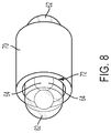
- FIG. 8 is a side perspective view of the tube in the sleeve.
- FIG. 9 is a side cross-sectional view of an alternative embodiment of a bait.
- FIG. 10 is a rear perspective view of an alternative embodiment of a bait.
- an artificial bait 10 includes a body portion 12 that is shaped to look like a type of live bait, in the example provided, a frog.
- the body is a hollow body formed from a spin-molded plastic such as, for example, polyvinylchloride or latex.
- the bait 10 can also include a hook 14 and line tie or eyelet 16 attached or connected to it.
- the hook 14 is a double hook with a first 38 and second points 38 ′.
- the eyelet 16 includes a first ring 20 and a second ring 22 connected by a bar 24 .
- the eyelet 16 is attached to the body 12 , in the embodiment shown in FIG. 4 , by inserting the second ring 22 through a first opening 26 in the body near the head or front.
- the material forming the body 12 has sufficient resilience such that the first opening 26 can expand to permit the second ring 22 to pass through the first opening 26 and into the interior cavity or hollow space 28 of the body and then contract back around the bar 24 .
- the first opening 26 is sized smaller than the bar 24 such that when the eyelet 16 is attached to the body 12 , a sealed is formed around the bar by the body to prevent water from entering the first opening.
- the double hook 14 may be attached to the artificial bait 10 by extending a first end of the hook through the second ring 22 in the cavity 28 of the hollow member or body 12 .
- This connection or attachment of the hook 14 to the eyelet 16 allows the hook to move and change its angle when a fish strikes such that the tips or points 38 are in position to engage the fish's mouth.
- other means are known in the industry for attaching a hook to an artificial bait.
- the body includes another opening 30 formed near or on the bottom side of the body 12 , and as shown in the embodiment seen in FIG. 4 , permits a portion of each of the two hooks to extend out of the cavity 28 .
- each end of hook 14 exits the opening 30 and extends up and around a side of the body 12 .
- a second opening 32 can be formed in the body 12 such as to accommodate a weight 34 .
- the second opening 32 is located at the bottom side and towards the rear or tail of the body 12 .
- the second opening 32 can hold the weight 34 such as, by example, permitting a portion of the weight to enter the cavity 28 .
- the second opening 32 can be sized smaller than the weight 34 such that after permitting a portion of the weight to enter the cavity 28 , the third opening can contract back and form a seal around a groove 36 in the weight.
- the weight 34 could additionally or alternatively be glued to the body 12 . The weight helps ensure that after being cast, for example, or after being reeled or pulled, the bottom of the bait is downwards, and the top of the artificial bait is upwards to present a lifelike appearance to a fish.
- hook or hooks with points that are directed downward, e.g. towards the bottom of the bait, or parallel to the bottom, to prevent the bait from snagging or catching on objects in or around the water, e.g. lily pads, tree limbs, etc.
- One disadvantage of hook points directed downwards is that when a fish comes up from the water to bite the bait, the points are not in an optimal position to engage the fish's mouth. Thus, the fisherman or woman may not hook the fish.
- the points 38 of the hook 14 are pointed upwards and towards the front of the bait 10 .
- the points are located in channels or pockets 40 formed in the topside and exterior surface of the body 12 .
- the first tip 38 is located in a first pocket 40 formed in a first side 48 of the body 12 and the second tip 38 ′ is located in a second pocket 40 ′ formed in a second side 52 of the body such that the tips are adjacent a top side of the body 12 .
- the pockets 40 , 41 ′ seen in FIG. 3 are located adjacent the rear of the body 12 .
- the pockets 40 reduces the ability for objects such as lily pads from engaging and catching on the points 38 of the hooks 14 .
- the resilient nature of the material forming the body 12 permits the body and/or pockets 40 to deform or collapse when a fish bites or strikes the bait 10 exposing the points 38 and permitting the fish's mouth to engage the points 38 .
- a number of techniques are used to fish with artificial bait which are known in the industry.
- One technique is known as “walking” the bait. The technique starts by casting the bait out into or around the water, e.g. on lily pads. The fisherman or woman then points the rod down or towards the water and whips or pulls the tip of the rod back towards him or her while reeling in the line. Because no two whips or pulls are the same, the bait will be pulled and engage the water in a zig-zag manner, as shown in FIG. 6 , which is attractive to fish. However, this technique is difficult to perform as it is difficult to get the bait to engage the water such that the bait zigs and zags like that of live bait.
- the body 12 includes one or more keels.
- the embodiment seen in FIG. 5 includes a first keel 42 located along the center of the underside or bottom side 44 of the body 12 , a second keel 46 along a first side 48 of the body and a third keel 50 along a second side 52 of the body.
- the keels 42 , 46 , 50 each have an end adjacent the front of the body 12 .
- the space between the first keel 42 and one of the second keel 46 and third keel 50 creates a first pathway 54 and second pathway 56 respectively for water to flow while the bait is in the water. As the bait 10 is “walked,” the water will engage the two pathways 54 , 56 .
- FIG. 5 includes a first keel 42 located along the center of the underside or bottom side 44 of the body 12 , a second keel 46 along a first side 48 of the body and a third keel 50 along a second side 52 of the body.
- the keels 42 , 46 , 50 are integrally formed in the exterior surface of the body 12 , however keels could be attached in any manner, e.g. glued, welded, fastened, etc., known in the industry, the use of which would not defeat the spirit of the invention.
- Keels 42 , 46 , 50 help prevent the bait 10 from realigning its longitudinal axis 58 towards the direction of pull and instead promote the bait to move back towards the direction of pull at first angle with a first pull and at a second angle with a second pull to obtain the desired zigzagging.
- the first side keel 46 will engage the water more than the second side keel 50 and the bait 10 will move to a position on the first side of the body.
- one embodiment includes a moving eye such as that taught in U.S. Pat. Nos. 10,575,506 and 10,244,741.
- the body 12 as seen in FIG. 7 has a hole or bore 60 formed therein in the general location of where an eye would be of the live bait which the artificial bait 10 is attempting to mimic.
- a tube 62 is located or positioned in the hole 60 .
- the tube 62 extends from a first side of the body 12 to the second side of the body.
- the tube 62 can include one or more noise making elements 64 , e.g. balls or ball bearings, located in the tube that make a noise and vibration when they contact each other and/or the tube.
- the tube 62 may be made from a material that permits light through the material such that at least one ball 64 is visible through the tube when the at least one ball is located near one of the first end and second end of the tube.
- the body 12 forms a seal around the tube 62 to prevent water from entering the body 12 and causing the bait 10 not to perform as desired.
- the hole 60 is sized smaller than the tube 62 such that the resilient nature of the material forming the body permits that hole to expand to receive the tube, but then contracts back to contact the tube.
- the body 12 may have a third opening 60 formed therein on a first side 48 of the body to permit access to the cavity 28 and the body may have a fourth opening 60 ′ formed on the second side 52 opposite the first side to permit access to the cavity.
- a shoulder 66 may be formed as part of the body 12 around each of the openings 60 , 60 ′ in the cavity 28 .
- one embodiment of the shoulder 66 is a cylinder with a hole that aligns with the openings 60 , 60 ′ from the first 48 and second side 52 of the body.
- the end of the shoulder 66 incudes a bearing surface 68 .
- the tube 62 shown in FIG. 8 may be positioned at least partially through or located in a sleeve 70 .
- the sleeve 70 is shaped as a cylinder with each end of the cylinder having a bearing surface 72 .
- the resilient material forming the body 12 and shoulders 66 permit the hole 60 in the body 12 and shoulder 66 to expand to receive the tube 62 with sleeve 70 .
- the tube 62 with sleeve 70 is inserted through the hole 60 or extend through the openings 60 , 60 ′ such that one end of the tube extends or is visible from the third opening 60 and the second end of the tube extends or is visible from the fourth opening 60 ′.
- the sleeve 70 is located inside the cavity 28 of the body 12 such that the bearing surface 68 of one of the shoulders 66 contacts one of the bearing surfaces 72 of the sleeve and the bearing surface 68 of the other shoulder 66 contacts the bearing surface 72 on the other side of the sleeve.
- the contact between the bearing surfaces 68 , 72 forms a seal to prevent water from entering the cavity 28 when the bait 10 is used in water and to hold the tube 62 in the body 12 .
- the sleeve 70 can be further held in position inside the cavity 28 between the pair of shoulders 66 by fixing the sleeve to the interior surface of the body 12 forming the cavity.
- the sleeve 70 is siliconed to the interior surface of the body 12 .
- other means of fixing the sleeve 70 to the body 12 is known in the industry, including, epoxying, gluing, ultra or sonic binding, friction, welding, snap-fit, integrally forming the sleeve with the body, etc., the use of which would not defeat the spirit of the invention.
- the sleeve 70 provides protection to the tube 62 .
- the fish will bite onto the hook(s) 14 .
- the force may cause the tips or points 38 of the hook to rotate upwards and causing the hook to contact the sleeve 70 .
- the tube is made from glass. If the sleeve 70 were not present, the hook 14 would contact the tube 62 and could break the tube. The hook 14 can contact the sleeve 70 without breaking the tube.
- the bait 10 may also include other accessories.
- the rear of the body 12 includes holes for attaching one or more skirts 74 .
- the skirts 74 move in the water and when being retrieved and/or walked to look like legs of a frog to a fish. Different types of legs, skirts, hooks, etc. could be attached to the bait without defeating the spirit of the invention.
- the bait 10 ′ has a resilient member 76 between the hook 14 and the eyelet 16 .
- the resilient member 76 is a spring, however other resilient members are known in the industry, for example, rubber or plastic bands, pneumatic cylinders, etc., the use of which would not defeat the spirit of the invention.
- the eyelet 16 could be made from a resilient material such as rubber or plastic.
- the resilient member 76 can expand to allow the fish to get a better hold on the hook 14 before a fisherman or woman jerks the rod up causing the line to pull the bait and hook away from the fish and to engage the hook in the fish's mouth. Permitting the hook 14 to be pulled out away from the body 12 creates a hook gap, the distance between the tip 38 of the hook 14 and the body 12 , which can be helpful in hooking the fish. The hook 14 being able to be pulled out away from the body 12 also creates a delayed reaction between the time the fisherman or woman pulls the rod and line away from the fish and when the hook starts to move which creates additional momentum improving hook penetration in a fish's mouth.
- the bait 10 ′′ has a third pocket 40 ′′ located on the top surface of the body 12 .
- the hook 14 has a third point 38 ′′ located in the third pocket 40 ′′.
- the addition of a third pocket 40 ′′ and third point 38 ′′ increases the ability for one of the points to engage a fish's mouth, e.g. if the fish strikes from behind and above the bait 10 ′.
Landscapes
- Life Sciences & Earth Sciences (AREA)
- Environmental Sciences (AREA)
- Marine Sciences & Fisheries (AREA)
- Animal Husbandry (AREA)
- Biodiversity & Conservation Biology (AREA)
Abstract
A fishing bait having a body with at least one hook. The fishing bait may have one or more keels on the bottom side of the body. The hooks of the bait may be pointed upward and located in pockets formed in the body. The fishing bait may include a tube extending through the body with a noise making element within the tube.
Description
The present invention relates generally to the field of fishing. More particularly, the present invention relates to the field of baits.
Baits are used by fishing hobbyists and professionals to catch fish. Baits can be live, e.g. real fish, worms, frogs, etc. or artificial, which are made to look like or imitate live bait. Artificial baits come in a wide variety of shapes, sizes and configurations and can be relatively inexpensive. Further, artificial baits are versatile in that they can be tailored to attract a particular type of fish by changing one or more characteristics, for example, the shape or size.
One characteristic that may attract a fish is how lifelike the artificial baits appear to a fish, e.g. moving eyes. One aspect of a lure that can make the lure appear lifelike is the sound and/or vibrations it makes. Some prey or bait, e.g. invertebrates, sought after by fish, e.g. bass, make sounds and vibrations in the water that fish use to locate such prey. Some lures use rattles to mimic the sound and vibrations created by such prey to attract the sought-after fish.
One attempt to create a lifelike eye in the fishing industry, as seen in U.S. Pat. Nos. 10,575,506 and 10,244,741, by the inventor and owned by the owner of the present application, which are hereby incorporated herein for all purposes, was to use one or more balls in an enclosed housing. As the lure moves in the water, the ball(s) move from one side of the housing to the other creating a life-like appearance and a clicking sound as they contact each other and the housing.
It will be understood by those skilled in the art that one or more aspects of this invention can meet certain objectives, while one or more other aspects can lead to certain other objectives. Other objects, features, benefits and advantages of the present invention will be apparent in the summary and descriptions of the disclosed embodiment(s), and will be readily apparent to those skilled in the art. Such objects, features, benefits and advantages will be apparent from the above as taken in conjunction with the accompanying figures and all reasonable inferences to be drawn therefrom.
As shown in FIGS. 1-8 , an artificial bait 10 includes a body portion 12 that is shaped to look like a type of live bait, in the example provided, a frog. In the embodiment seen in FIG. 1 , the body is a hollow body formed from a spin-molded plastic such as, for example, polyvinylchloride or latex. However, other materials and means for making an artificial bait are known in the industry and the use of which would not defeat the spirit of the invention. The bait 10 can also include a hook 14 and line tie or eyelet 16 attached or connected to it. In the embodiment seen in FIG. 3 , the hook 14 is a double hook with a first 38 and second points 38′.
As seen in the embodiment illustrated in FIG. 4 , the eyelet 16 includes a first ring 20 and a second ring 22 connected by a bar 24. The eyelet 16 is attached to the body 12, in the embodiment shown in FIG. 4 , by inserting the second ring 22 through a first opening 26 in the body near the head or front. The material forming the body 12 has sufficient resilience such that the first opening 26 can expand to permit the second ring 22 to pass through the first opening 26 and into the interior cavity or hollow space 28 of the body and then contract back around the bar 24. The first opening 26 is sized smaller than the bar 24 such that when the eyelet 16 is attached to the body 12, a sealed is formed around the bar by the body to prevent water from entering the first opening.
The double hook 14 may be attached to the artificial bait 10 by extending a first end of the hook through the second ring 22 in the cavity 28 of the hollow member or body 12. This connection or attachment of the hook 14 to the eyelet 16 allows the hook to move and change its angle when a fish strikes such that the tips or points 38 are in position to engage the fish's mouth. However, other means are known in the industry for attaching a hook to an artificial bait. The body includes another opening 30 formed near or on the bottom side of the body 12, and as shown in the embodiment seen in FIG. 4 , permits a portion of each of the two hooks to extend out of the cavity 28. The opening 30 does not need to form a seal around the hook 14 because by being located at the bottom of the body 12, the air in the cavity 28 has no way to exit the cavity and thereby prevents the water from entering the cavity. However, other means for permitting a hook or hooks from exiting the body 12 of bait 10 are known in the industry, the use of which would not defeat the spirit of the invention. As seen in FIG. 3 , each end of hook 14 exits the opening 30 and extends up and around a side of the body 12.
A second opening 32 can be formed in the body 12 such as to accommodate a weight 34. In the embodiment seen in FIG. 4 , the second opening 32 is located at the bottom side and towards the rear or tail of the body 12. The second opening 32 can hold the weight 34 such as, by example, permitting a portion of the weight to enter the cavity 28. Like the first opening 26, the second opening 32 can be sized smaller than the weight 34 such that after permitting a portion of the weight to enter the cavity 28, the third opening can contract back and form a seal around a groove 36 in the weight. The weight 34 could additionally or alternatively be glued to the body 12. The weight helps ensure that after being cast, for example, or after being reeled or pulled, the bottom of the bait is downwards, and the top of the artificial bait is upwards to present a lifelike appearance to a fish.
Current artificial baits, for example frog baits, have a hook or hooks with points that are directed downward, e.g. towards the bottom of the bait, or parallel to the bottom, to prevent the bait from snagging or catching on objects in or around the water, e.g. lily pads, tree limbs, etc. One disadvantage of hook points directed downwards is that when a fish comes up from the water to bite the bait, the points are not in an optimal position to engage the fish's mouth. Thus, the fisherman or woman may not hook the fish.
In one embodiment of the present invention, such as that seen in FIG. 1 , the points 38 of the hook 14 are pointed upwards and towards the front of the bait 10. In order to prevent the points 38 of the hook 14 from snagging or catching on objects in or around the water, the points are located in channels or pockets 40 formed in the topside and exterior surface of the body 12. For example, as seen in FIG. 3 , the first tip 38 is located in a first pocket 40 formed in a first side 48 of the body 12 and the second tip 38′ is located in a second pocket 40′ formed in a second side 52 of the body such that the tips are adjacent a top side of the body 12. The pockets 40, 41′ seen in FIG. 3 are located adjacent the rear of the body 12. The pockets 40 reduces the ability for objects such as lily pads from engaging and catching on the points 38 of the hooks 14. However, the resilient nature of the material forming the body 12 permits the body and/or pockets 40 to deform or collapse when a fish bites or strikes the bait 10 exposing the points 38 and permitting the fish's mouth to engage the points 38.
A number of techniques are used to fish with artificial bait which are known in the industry. One technique is known as “walking” the bait. The technique starts by casting the bait out into or around the water, e.g. on lily pads. The fisherman or woman then points the rod down or towards the water and whips or pulls the tip of the rod back towards him or her while reeling in the line. Because no two whips or pulls are the same, the bait will be pulled and engage the water in a zig-zag manner, as shown in FIG. 6 , which is attractive to fish. However, this technique is difficult to perform as it is difficult to get the bait to engage the water such that the bait zigs and zags like that of live bait.
In one embodiment, the body 12 includes one or more keels. The embodiment seen in FIG. 5 includes a first keel 42 located along the center of the underside or bottom side 44 of the body 12, a second keel 46 along a first side 48 of the body and a third keel 50 along a second side 52 of the body. In one embodiment, the keels 42, 46, 50 each have an end adjacent the front of the body 12. The space between the first keel 42 and one of the second keel 46 and third keel 50 creates a first pathway 54 and second pathway 56 respectively for water to flow while the bait is in the water. As the bait 10 is “walked,” the water will engage the two pathways 54, 56. In the embodiment seen in FIG. 5 , the keels 42, 46, 50 are integrally formed in the exterior surface of the body 12, however keels could be attached in any manner, e.g. glued, welded, fastened, etc., known in the industry, the use of which would not defeat the spirit of the invention.
When a conventional bait is being “walked,” the bait will have a tendency to realign its longitudinal axis to be directed at the direction of pull and move towards that direction with little or no zigzagging, unless the fisherman or woman has experience with such technique. Keels 42, 46, 50 help prevent the bait 10 from realigning its longitudinal axis 58 towards the direction of pull and instead promote the bait to move back towards the direction of pull at first angle with a first pull and at a second angle with a second pull to obtain the desired zigzagging. For example, when the pull is from the first side 48 of the body, the first side keel 46 will engage the water more than the second side keel 50 and the bait 10 will move to a position on the first side of the body.
As discussed above, one embodiment includes a moving eye such as that taught in U.S. Pat. Nos. 10,575,506 and 10,244,741. The body 12 as seen in FIG. 7 has a hole or bore 60 formed therein in the general location of where an eye would be of the live bait which the artificial bait 10 is attempting to mimic. A tube 62 is located or positioned in the hole 60. As seen in FIG. 2 , the tube 62 extends from a first side of the body 12 to the second side of the body. The tube 62 can include one or more noise making elements 64, e.g. balls or ball bearings, located in the tube that make a noise and vibration when they contact each other and/or the tube. The tube 62 may be made from a material that permits light through the material such that at least one ball 64 is visible through the tube when the at least one ball is located near one of the first end and second end of the tube.
The body 12 forms a seal around the tube 62 to prevent water from entering the body 12 and causing the bait 10 not to perform as desired. In one embodiment the hole 60 is sized smaller than the tube 62 such that the resilient nature of the material forming the body permits that hole to expand to receive the tube, but then contracts back to contact the tube.
Alternatively or additionally, the body 12 may have a third opening 60 formed therein on a first side 48 of the body to permit access to the cavity 28 and the body may have a fourth opening 60′ formed on the second side 52 opposite the first side to permit access to the cavity.
A shoulder 66 may be formed as part of the body 12 around each of the openings 60, 60′ in the cavity 28. As seen in FIG. 7 , one embodiment of the shoulder 66 is a cylinder with a hole that aligns with the openings 60, 60′ from the first 48 and second side 52 of the body. The end of the shoulder 66 incudes a bearing surface 68.
The tube 62 shown in FIG. 8 may be positioned at least partially through or located in a sleeve 70. The sleeve 70 is shaped as a cylinder with each end of the cylinder having a bearing surface 72.
The resilient material forming the body 12 and shoulders 66 permit the hole 60 in the body 12 and shoulder 66 to expand to receive the tube 62 with sleeve 70. The tube 62 with sleeve 70 is inserted through the hole 60 or extend through the openings 60, 60′ such that one end of the tube extends or is visible from the third opening 60 and the second end of the tube extends or is visible from the fourth opening 60′. The sleeve 70 is located inside the cavity 28 of the body 12 such that the bearing surface 68 of one of the shoulders 66 contacts one of the bearing surfaces 72 of the sleeve and the bearing surface 68 of the other shoulder 66 contacts the bearing surface 72 on the other side of the sleeve. The contact between the bearing surfaces 68, 72 forms a seal to prevent water from entering the cavity 28 when the bait 10 is used in water and to hold the tube 62 in the body 12.
The sleeve 70 can be further held in position inside the cavity 28 between the pair of shoulders 66 by fixing the sleeve to the interior surface of the body 12 forming the cavity. In one embodiment, the sleeve 70 is siliconed to the interior surface of the body 12. However, other means of fixing the sleeve 70 to the body 12 is known in the industry, including, epoxying, gluing, ultra or sonic binding, friction, welding, snap-fit, integrally forming the sleeve with the body, etc., the use of which would not defeat the spirit of the invention.
The sleeve 70 provides protection to the tube 62. When a fish strikes or bites the bait 10, the fish will bite onto the hook(s) 14. The force may cause the tips or points 38 of the hook to rotate upwards and causing the hook to contact the sleeve 70. In one embodiment, the tube is made from glass. If the sleeve 70 were not present, the hook 14 would contact the tube 62 and could break the tube. The hook 14 can contact the sleeve 70 without breaking the tube.
The bait 10 may also include other accessories. For example, as seen in FIG. 3 , the rear of the body 12 includes holes for attaching one or more skirts 74. The skirts 74 move in the water and when being retrieved and/or walked to look like legs of a frog to a fish. Different types of legs, skirts, hooks, etc. could be attached to the bait without defeating the spirit of the invention.
In another embodiment seen in FIG. 9 , the bait 10′ has a resilient member 76 between the hook 14 and the eyelet 16. In the embodiment seen in FIG. 9 , the resilient member 76 is a spring, however other resilient members are known in the industry, for example, rubber or plastic bands, pneumatic cylinders, etc., the use of which would not defeat the spirit of the invention. Alternatively, the eyelet 16 could be made from a resilient material such as rubber or plastic.
When a fish strikes the bait 10′, the resilient member 76 can expand to allow the fish to get a better hold on the hook 14 before a fisherman or woman jerks the rod up causing the line to pull the bait and hook away from the fish and to engage the hook in the fish's mouth. Permitting the hook 14 to be pulled out away from the body 12 creates a hook gap, the distance between the tip 38 of the hook 14 and the body 12, which can be helpful in hooking the fish. The hook 14 being able to be pulled out away from the body 12 also creates a delayed reaction between the time the fisherman or woman pulls the rod and line away from the fish and when the hook starts to move which creates additional momentum improving hook penetration in a fish's mouth.
In another embodiment seen in FIG. 10 , the bait 10″ has a third pocket 40″ located on the top surface of the body 12. The hook 14 has a third point 38″ located in the third pocket 40″. The addition of a third pocket 40″ and third point 38″ increases the ability for one of the points to engage a fish's mouth, e.g. if the fish strikes from behind and above the bait 10′.
Although the invention has been herein described in what is perceived to be the most practical and preferred embodiments, it is to be understood that the invention is not intended to be limited to the specific embodiments set forth above. Rather, it is recognized that modifications may be made by one of skill in the art of the invention without departing from the spirit or intent of the invention and, therefore, the invention is to be taken as including all reasonable equivalents to the subject matter of the appended claims and the description of the invention herein.
Claims (10)
1. An artificial fishing bait comprising:
a hollow member;
a hook attached to the hollow member; and
a line tie attached to the hollow member;
at least one keel located on the bottom of said hollow member;
wherein the at least one keel is arranged to form first and second pathways which promote a zig-zag effect during retrieval of said fishing bait.
2. The artificial fishing bait of claim 1 , further comprising:
a second keel on the exterior surface of the hollow member; and
a third keel on the exterior surface of the hollow member;
wherein the first pathway is located between the at least one keel and the second keel and the second pathway is located between the at least one keel and the third keel.
3. The artificial fishing bait of claim 2 , wherein the first keel, second keel and third keel each have an end located adjacent to a front of the hollow member.
4. The artificial fishing bait of claim 3 wherein the first keel, second keel and third keel are integrally formed in the hollow member.
5. The artificial fishing bait of claim 4 , wherein the hollow member has a first opening configured to attach the line tie to the hollow member.
6. The artificial fishing bait of claim 5 , wherein the hollow member has a second opening configured to attach a weight to the bottom side of the hollow member.
7. The artificial fishing bait of claim 6 , wherein the hollow member has a third opening on the first side of the hollow member and a fourth hole on the second side of the hollow member;
wherein a tube extends through the third opening and forth opening such that one end of the tube is visible from the third opening and a second end of the tube is visible from the fourth opening; and
wherein at least one ball is located in the tube and is configured to create a noise and vibration when the at least one ball contacts the tube.
8. The artificial fishing bait of claim 7 , wherein the tube is made from a material that permits light through the material; and wherein the at least one ball is visible through the tube when the at least one ball is located adjacent to one of the first end and second end.
9. The artificial fishing bait of claim 1 , wherein the hollow member forms a hollow space;
wherein a first end of the hook is located in the hollow space; and
wherein a point of the hook is located outside the hollow space and adjacent a top side of the hollow member.
10. The artificial fishing bait of claim 9 , wherein a portion of the hook extends out of the hollow space through an opening in the bottom side of the hollow member.
Priority Applications (1)
| Application Number | Priority Date | Filing Date | Title |
|---|---|---|---|
| US16/816,744 US10888073B1 (en) | 2020-03-12 | 2020-03-12 | Bait |
Applications Claiming Priority (1)
| Application Number | Priority Date | Filing Date | Title |
|---|---|---|---|
| US16/816,744 US10888073B1 (en) | 2020-03-12 | 2020-03-12 | Bait |
Publications (1)
| Publication Number | Publication Date |
|---|---|
| US10888073B1 true US10888073B1 (en) | 2021-01-12 |
Family
ID=74066882
Family Applications (1)
| Application Number | Title | Priority Date | Filing Date |
|---|---|---|---|
| US16/816,744 Active US10888073B1 (en) | 2020-03-12 | 2020-03-12 | Bait |
Country Status (1)
| Country | Link |
|---|---|
| US (1) | US10888073B1 (en) |
Cited By (1)
| Publication number | Priority date | Publication date | Assignee | Title |
|---|---|---|---|---|
| US20210244008A1 (en) * | 2016-01-08 | 2021-08-12 | Olivier Portrat | Bait Drive Unit and Bait Fish having a Bait Drive Unit |
Citations (69)
| Publication number | Priority date | Publication date | Assignee | Title |
|---|---|---|---|---|
| US1583199A (en) * | 1922-06-09 | 1926-05-04 | Walter C Taylor | Artificial bait for fish |
| US2250478A (en) * | 1939-09-11 | 1941-07-29 | Wayne M Franks | Artificial bait |
| US2575797A (en) * | 1950-01-06 | 1951-11-20 | Corsi Peter Paul | Fish lure |
| US2749646A (en) * | 1954-05-21 | 1956-06-12 | Irvin B Hall | Lure casting device |
| US3105317A (en) * | 1961-10-09 | 1963-10-01 | Robert L Fox | Fish lure |
| US3750321A (en) | 1972-04-17 | 1973-08-07 | Mcclellan Ind Inc | Artificial lure for fishing |
| US3855722A (en) | 1973-06-06 | 1974-12-24 | J Moore | Fishing lure construction |
| US3881272A (en) | 1973-10-01 | 1975-05-06 | Douglas W Parker | Fishing lure eye assembly |
| US3909974A (en) | 1973-12-19 | 1975-10-07 | Leslie Wayne Kent | Artificial fishing lure |
| US4045903A (en) | 1976-02-02 | 1977-09-06 | Parker Douglas W | Artificial fishing lure |
| FI61388C (en) | 1980-07-17 | 1982-08-10 | Kuusamon Uistin Paavo Korpua P | BETE |
| US4712326A (en) | 1986-07-14 | 1987-12-15 | Hoover Gary W | Noisemaking fishing lure |
| US4785569A (en) | 1987-09-14 | 1988-11-22 | Thomas Jr Cecil L | Fishing lure and lure retaining device |
| US4791750A (en) | 1988-03-15 | 1988-12-20 | Gammill Roy M | Fishing lure with internal rattle |
| US4807383A (en) | 1988-04-20 | 1989-02-28 | Delwiche Reginald J | Alterable, wear resistant fishing hook assembly |
| US4858370A (en) * | 1988-07-12 | 1989-08-22 | Ryder International Corporation | Fishing lure for simulated feeding |
| US5131181A (en) * | 1991-04-01 | 1992-07-21 | Scott Steinke | One legged frog fish lure |
| US5546694A (en) * | 1995-04-11 | 1996-08-20 | Wilkinson; F. Charles | Simulated crab lure |
| US5588246A (en) | 1995-04-27 | 1996-12-31 | Hill; Curtis J. | Interchangeable eyes for fishing lures |
| US5806234A (en) | 1996-09-09 | 1998-09-15 | D.O.A. Lures, Inc. | Fishing lure jig head and body |
| US5918405A (en) | 1997-07-23 | 1999-07-06 | Cotee Industries, Inc. | Modular fishing lure |
| US5926994A (en) | 1997-10-07 | 1999-07-27 | Mason; Marvin Howard | Artificial fishing lure |
| US5926993A (en) | 1997-07-23 | 1999-07-27 | Cotee Industries, Inc. | Modular fishing lure kit |
| US5946847A (en) | 1995-06-30 | 1999-09-07 | North; Dennis C. | Clicking capsules for fishing lures |
| US6061948A (en) | 1998-07-23 | 2000-05-16 | Boucek; Kenneth Paul | Adaptably mountable head with eyes for attachment to fishing lures |
| US6212818B1 (en) | 1998-10-05 | 2001-04-10 | Samuel M. Huddleston | Soft bait fish lure |
| US6651376B1 (en) | 2002-06-26 | 2003-11-25 | Skirts Plus Corporation | Method and apparatus for attracting fish using a sound producing fishing accessory providing blind positive engagement to a hook |
| US6675526B1 (en) * | 2001-03-08 | 2004-01-13 | Wanabe Outdoors, Inc. | Artificial bait fish |
| US6865842B2 (en) | 2000-12-20 | 2005-03-15 | S&C Brinkman Corp. | Fish catching system |
| US20050223620A1 (en) | 2004-04-13 | 2005-10-13 | Pixton Dennis N | Rattle for attracting fish |
| US20060042147A1 (en) | 2004-09-01 | 2006-03-02 | Jenkins Richard T | Interchangeable trolling system |
| US20060075678A1 (en) * | 2004-10-13 | 2006-04-13 | Charles Schammel | Artificial eye assembly for improving the hydrodynamic performance and attractiveness of a trolled baitfish |
| US20060260178A1 (en) * | 2005-05-23 | 2006-11-23 | Normark Corporation | Hook stabilizing device for a fishing lure |
| US20080083154A1 (en) * | 2006-10-05 | 2008-04-10 | Timothy M Gregory | Bait retention fish hook |
| US20090113783A1 (en) | 2007-11-07 | 2009-05-07 | Hollomon Michael E | Fishing aid |
| US20090183418A1 (en) * | 2008-01-23 | 2009-07-23 | River2Sea, Llc | Swimming frog lure and method |
| US7614178B2 (en) | 2007-09-14 | 2009-11-10 | Rex Harrison Hoyt | Resonating jig head |
| US20090277071A1 (en) | 2008-05-12 | 2009-11-12 | Z-Man Fishing Products, Inc. | Fishing lure |
| US20090307960A1 (en) * | 2008-06-17 | 2009-12-17 | Mann's Bait Company, Inc. | Hollow bait and method of making the same |
| US20100000145A1 (en) * | 2008-07-07 | 2010-01-07 | Normark Innovations, Inc. | Fishing Lure Having Lateral Ball Movement Within a Tube |
| US20100229453A1 (en) | 2009-03-11 | 2010-09-16 | Southern Lure Company | Jig head with a rattle |
| US20100263259A1 (en) * | 2009-04-16 | 2010-10-21 | Kenzie Cuthbert | Fishing lure, method of making a fishing lure and a fishing lure kit |
| US7827730B1 (en) | 2007-06-07 | 2010-11-09 | Ebsco Industries, Inc. | Fishing lure having a controlled rattle |
| US8037635B1 (en) * | 2009-02-13 | 2011-10-18 | Wyatt Christopher A | Frog fishing lure system |
| US8091271B2 (en) * | 2007-11-26 | 2012-01-10 | Mayer James D | Blood-simulating fishing lure |
| US8316576B1 (en) | 2009-05-23 | 2012-11-27 | Ebsco Industries, Inc. | Diving rattle lure |
| US20130051779A1 (en) * | 2011-08-25 | 2013-02-28 | Robert Bradley Londeree | Towable directed-view underwater camera carrier |
| US20130074395A1 (en) * | 2010-09-27 | 2013-03-28 | Jack Anthony Farr, Jr. | Fishing lure with movable parts |
| US20130081319A1 (en) * | 2011-10-04 | 2013-04-04 | Jason Scott | Fish Lure |
| US20130152450A1 (en) | 2011-12-16 | 2013-06-20 | Gregory Myerson | Fishing lure |
| US20130318858A1 (en) * | 2012-05-31 | 2013-12-05 | Victor J. Cook, Jr. | Diving Lip For A Fishing Lure |
| US8601737B2 (en) | 2005-02-10 | 2013-12-10 | Chad Wiskow | Rattle-type fishing tackle component |
| US20140013648A1 (en) * | 2012-07-10 | 2014-01-16 | Centro Corporation | Fishing Lure With Retractable Hook |
| US20140115944A1 (en) * | 2011-09-21 | 2014-05-01 | Kenneth Dale Thomas | Bait mimicking insertable fishing lure module |
| US20140317992A1 (en) * | 2013-04-26 | 2014-10-30 | Christopher James Morgan | Hovering fishing lure assembly |
| US9173385B2 (en) | 2013-08-14 | 2015-11-03 | Dennis Cooper | Rattling jig |
| US20150373959A1 (en) * | 2013-04-26 | 2015-12-31 | Christopher James Morgan | Hovering fishing lure assembly |
| US20160007581A1 (en) * | 2006-03-21 | 2016-01-14 | Kent G. Davidson | Fishing Lure For Implementing A Fishing Contest |
| US20160113257A1 (en) | 2014-10-28 | 2016-04-28 | Allen James Harrington | Rattling Swimbait Jig Head |
| US20160157471A1 (en) * | 2014-12-04 | 2016-06-09 | Normark Innovations, Inc. | Fishing lure having a dying minnow action |
| US9474257B1 (en) * | 2010-04-26 | 2016-10-25 | Robert McGilvry | Imitation crawdad artificial fishing lure |
| US20180000058A1 (en) * | 2016-06-30 | 2018-01-04 | Plastic Research And Development Corporation | Rattling soft body lure |
| US20180042206A1 (en) | 2016-08-13 | 2018-02-15 | Joshua Aaron St. John | Swimbaits with Fluttering Dual Plane Tail Rotation |
| US20180360011A1 (en) * | 2017-06-15 | 2018-12-20 | Domkos Investments, Inc. | Spring Actuated Weedless Fishing Lure |
| US20180360013A1 (en) * | 2017-06-20 | 2018-12-20 | Steven Edward Breunig | Fishing lure trolling spreader bar |
| US20190000052A1 (en) * | 2017-06-28 | 2019-01-03 | Scott Stephen Garman | Durable snagless soft-bodied fishing lure |
| US20190008128A1 (en) | 2017-07-10 | 2019-01-10 | Justice Tackle & Co., Llc | Fishing lure with interchangeable body and head segments |
| US10244741B1 (en) * | 2018-05-03 | 2019-04-02 | Hard and Soft Fishing, Inc. | Lure |
| USD858685S1 (en) * | 2017-07-11 | 2019-09-03 | Koppers Fishing And Tackle Corp. | Fishing lure |
-
2020
- 2020-03-12 US US16/816,744 patent/US10888073B1/en active Active
Patent Citations (71)
| Publication number | Priority date | Publication date | Assignee | Title |
|---|---|---|---|---|
| US1583199A (en) * | 1922-06-09 | 1926-05-04 | Walter C Taylor | Artificial bait for fish |
| US2250478A (en) * | 1939-09-11 | 1941-07-29 | Wayne M Franks | Artificial bait |
| US2575797A (en) * | 1950-01-06 | 1951-11-20 | Corsi Peter Paul | Fish lure |
| US2749646A (en) * | 1954-05-21 | 1956-06-12 | Irvin B Hall | Lure casting device |
| US3105317A (en) * | 1961-10-09 | 1963-10-01 | Robert L Fox | Fish lure |
| US3750321A (en) | 1972-04-17 | 1973-08-07 | Mcclellan Ind Inc | Artificial lure for fishing |
| US3855722A (en) | 1973-06-06 | 1974-12-24 | J Moore | Fishing lure construction |
| US3881272A (en) | 1973-10-01 | 1975-05-06 | Douglas W Parker | Fishing lure eye assembly |
| US3909974A (en) | 1973-12-19 | 1975-10-07 | Leslie Wayne Kent | Artificial fishing lure |
| US4045903A (en) | 1976-02-02 | 1977-09-06 | Parker Douglas W | Artificial fishing lure |
| FI61388C (en) | 1980-07-17 | 1982-08-10 | Kuusamon Uistin Paavo Korpua P | BETE |
| US4712326A (en) | 1986-07-14 | 1987-12-15 | Hoover Gary W | Noisemaking fishing lure |
| US4785569A (en) | 1987-09-14 | 1988-11-22 | Thomas Jr Cecil L | Fishing lure and lure retaining device |
| US4791750A (en) | 1988-03-15 | 1988-12-20 | Gammill Roy M | Fishing lure with internal rattle |
| US4807383A (en) | 1988-04-20 | 1989-02-28 | Delwiche Reginald J | Alterable, wear resistant fishing hook assembly |
| US4858370A (en) * | 1988-07-12 | 1989-08-22 | Ryder International Corporation | Fishing lure for simulated feeding |
| US5131181A (en) * | 1991-04-01 | 1992-07-21 | Scott Steinke | One legged frog fish lure |
| US5546694A (en) * | 1995-04-11 | 1996-08-20 | Wilkinson; F. Charles | Simulated crab lure |
| US5588246A (en) | 1995-04-27 | 1996-12-31 | Hill; Curtis J. | Interchangeable eyes for fishing lures |
| US5946847A (en) | 1995-06-30 | 1999-09-07 | North; Dennis C. | Clicking capsules for fishing lures |
| US5806234A (en) | 1996-09-09 | 1998-09-15 | D.O.A. Lures, Inc. | Fishing lure jig head and body |
| US5918405A (en) | 1997-07-23 | 1999-07-06 | Cotee Industries, Inc. | Modular fishing lure |
| US5926993A (en) | 1997-07-23 | 1999-07-27 | Cotee Industries, Inc. | Modular fishing lure kit |
| US5926994A (en) | 1997-10-07 | 1999-07-27 | Mason; Marvin Howard | Artificial fishing lure |
| US6061948A (en) | 1998-07-23 | 2000-05-16 | Boucek; Kenneth Paul | Adaptably mountable head with eyes for attachment to fishing lures |
| US6212818B1 (en) | 1998-10-05 | 2001-04-10 | Samuel M. Huddleston | Soft bait fish lure |
| US6865842B2 (en) | 2000-12-20 | 2005-03-15 | S&C Brinkman Corp. | Fish catching system |
| US6675526B1 (en) * | 2001-03-08 | 2004-01-13 | Wanabe Outdoors, Inc. | Artificial bait fish |
| US6651376B1 (en) | 2002-06-26 | 2003-11-25 | Skirts Plus Corporation | Method and apparatus for attracting fish using a sound producing fishing accessory providing blind positive engagement to a hook |
| US20050223620A1 (en) | 2004-04-13 | 2005-10-13 | Pixton Dennis N | Rattle for attracting fish |
| US20060042147A1 (en) | 2004-09-01 | 2006-03-02 | Jenkins Richard T | Interchangeable trolling system |
| US20060075678A1 (en) * | 2004-10-13 | 2006-04-13 | Charles Schammel | Artificial eye assembly for improving the hydrodynamic performance and attractiveness of a trolled baitfish |
| US8601737B2 (en) | 2005-02-10 | 2013-12-10 | Chad Wiskow | Rattle-type fishing tackle component |
| US20060260178A1 (en) * | 2005-05-23 | 2006-11-23 | Normark Corporation | Hook stabilizing device for a fishing lure |
| US20160007581A1 (en) * | 2006-03-21 | 2016-01-14 | Kent G. Davidson | Fishing Lure For Implementing A Fishing Contest |
| US20080083154A1 (en) * | 2006-10-05 | 2008-04-10 | Timothy M Gregory | Bait retention fish hook |
| US7827730B1 (en) | 2007-06-07 | 2010-11-09 | Ebsco Industries, Inc. | Fishing lure having a controlled rattle |
| US7614178B2 (en) | 2007-09-14 | 2009-11-10 | Rex Harrison Hoyt | Resonating jig head |
| US20090113783A1 (en) | 2007-11-07 | 2009-05-07 | Hollomon Michael E | Fishing aid |
| US8091271B2 (en) * | 2007-11-26 | 2012-01-10 | Mayer James D | Blood-simulating fishing lure |
| US20090183418A1 (en) * | 2008-01-23 | 2009-07-23 | River2Sea, Llc | Swimming frog lure and method |
| US20090277071A1 (en) | 2008-05-12 | 2009-11-12 | Z-Man Fishing Products, Inc. | Fishing lure |
| US20090307960A1 (en) * | 2008-06-17 | 2009-12-17 | Mann's Bait Company, Inc. | Hollow bait and method of making the same |
| US20100000145A1 (en) * | 2008-07-07 | 2010-01-07 | Normark Innovations, Inc. | Fishing Lure Having Lateral Ball Movement Within a Tube |
| US8037635B1 (en) * | 2009-02-13 | 2011-10-18 | Wyatt Christopher A | Frog fishing lure system |
| US20100229453A1 (en) | 2009-03-11 | 2010-09-16 | Southern Lure Company | Jig head with a rattle |
| US20100263259A1 (en) * | 2009-04-16 | 2010-10-21 | Kenzie Cuthbert | Fishing lure, method of making a fishing lure and a fishing lure kit |
| US8316576B1 (en) | 2009-05-23 | 2012-11-27 | Ebsco Industries, Inc. | Diving rattle lure |
| US9474257B1 (en) * | 2010-04-26 | 2016-10-25 | Robert McGilvry | Imitation crawdad artificial fishing lure |
| US8910415B2 (en) | 2010-09-27 | 2014-12-16 | Jack Anthony Farr, Jr. | Fishing lure with movable parts |
| US20130074395A1 (en) * | 2010-09-27 | 2013-03-28 | Jack Anthony Farr, Jr. | Fishing lure with movable parts |
| US20130051779A1 (en) * | 2011-08-25 | 2013-02-28 | Robert Bradley Londeree | Towable directed-view underwater camera carrier |
| US20140115944A1 (en) * | 2011-09-21 | 2014-05-01 | Kenneth Dale Thomas | Bait mimicking insertable fishing lure module |
| US20130081319A1 (en) * | 2011-10-04 | 2013-04-04 | Jason Scott | Fish Lure |
| US20130152450A1 (en) | 2011-12-16 | 2013-06-20 | Gregory Myerson | Fishing lure |
| US20130318858A1 (en) * | 2012-05-31 | 2013-12-05 | Victor J. Cook, Jr. | Diving Lip For A Fishing Lure |
| US20140013648A1 (en) * | 2012-07-10 | 2014-01-16 | Centro Corporation | Fishing Lure With Retractable Hook |
| US20140317992A1 (en) * | 2013-04-26 | 2014-10-30 | Christopher James Morgan | Hovering fishing lure assembly |
| US20150373959A1 (en) * | 2013-04-26 | 2015-12-31 | Christopher James Morgan | Hovering fishing lure assembly |
| US9173385B2 (en) | 2013-08-14 | 2015-11-03 | Dennis Cooper | Rattling jig |
| US20160113257A1 (en) | 2014-10-28 | 2016-04-28 | Allen James Harrington | Rattling Swimbait Jig Head |
| US20160157471A1 (en) * | 2014-12-04 | 2016-06-09 | Normark Innovations, Inc. | Fishing lure having a dying minnow action |
| US20180000058A1 (en) * | 2016-06-30 | 2018-01-04 | Plastic Research And Development Corporation | Rattling soft body lure |
| US20180042206A1 (en) | 2016-08-13 | 2018-02-15 | Joshua Aaron St. John | Swimbaits with Fluttering Dual Plane Tail Rotation |
| US20180360011A1 (en) * | 2017-06-15 | 2018-12-20 | Domkos Investments, Inc. | Spring Actuated Weedless Fishing Lure |
| US20180360013A1 (en) * | 2017-06-20 | 2018-12-20 | Steven Edward Breunig | Fishing lure trolling spreader bar |
| US20190000052A1 (en) * | 2017-06-28 | 2019-01-03 | Scott Stephen Garman | Durable snagless soft-bodied fishing lure |
| US20190008128A1 (en) | 2017-07-10 | 2019-01-10 | Justice Tackle & Co., Llc | Fishing lure with interchangeable body and head segments |
| USD858685S1 (en) * | 2017-07-11 | 2019-09-03 | Koppers Fishing And Tackle Corp. | Fishing lure |
| US10244741B1 (en) * | 2018-05-03 | 2019-04-02 | Hard and Soft Fishing, Inc. | Lure |
| US10575506B2 (en) | 2018-05-03 | 2020-03-03 | Rmb Importing, Llc | Lure |
Non-Patent Citations (7)
| Title |
|---|
| Article on Jackall lure, by Wollbugger, Sep. 2, 2014 http://www.tackletour.com/reviewjackalliobee.html. * |
| http://web.archive.org/web/20120109072551/http://www.basspro.com/Bass-Pro-Shops-Tourney-Rattle-Bait/product/10225063/; website screenshot for the Bass Pro Shops Tourney Rattle Bait; Jan. 9, 2012. |
| http://web.archive.org/web/20150923000105/http://www.fleetfarm.com/detail/southern-pro-tackle-rattle-eye-jig-orange/000000090151; website screenshot for the Southern Pro Tackle Rattle Eye Jig Orange; Sep. 23, 2015. |
| https://allsharktankproducts.com/shark-tank-products-sports/the-world-record-striper-company-fishing-lures-and-tackle/; website screenshot for the Fishing Lures and Tackle; May 19, 2015. |
| Website screenshot; https://www.booyahbaits.com/lures/frogs; BOOYAH Hollow Body Frogs; Mar. 6, 2020. |
| Website screenshot; https://www.youtube.com/watch?v=ghdWBcj2rYo; ICAST 2009—Snag Proof Ish's Phat Frog; Oct. 23, 2009. |
| Website screenshot; https://zoombait.com/2019/09/zoom-releases-new-hollow-body-frog; Zoom releases new Hollow Body Frog; Mar. 6, 2020. |
Cited By (1)
| Publication number | Priority date | Publication date | Assignee | Title |
|---|---|---|---|---|
| US20210244008A1 (en) * | 2016-01-08 | 2021-08-12 | Olivier Portrat | Bait Drive Unit and Bait Fish having a Bait Drive Unit |
Similar Documents
| Publication | Publication Date | Title |
|---|---|---|
| US8079173B2 (en) | Fishing lure with weighted hydrodynamic head, mated plastic worm and pivoting hook | |
| US8020338B2 (en) | Spitting weedless surface fishing lure | |
| US8091271B2 (en) | Blood-simulating fishing lure | |
| US20190000053A1 (en) | Expanding or Contracting Fishing Lure | |
| US9253966B2 (en) | Fishing lure | |
| US9504237B2 (en) | Rubber or soft plastic fishing spoon lure | |
| US20100000145A1 (en) | Fishing Lure Having Lateral Ball Movement Within a Tube | |
| US5893232A (en) | Natural bait holding fishing lure | |
| US8938907B2 (en) | Anti-snag fishing device | |
| US20050210731A1 (en) | Snag-resistant fishing lure | |
| US9185892B2 (en) | Fishing lure imitating a bird | |
| US8196336B2 (en) | Fishing lure and accessory | |
| US11844338B1 (en) | Fishing lure | |
| US9060499B2 (en) | Fishing rig and method of assembling same | |
| US6237276B1 (en) | Levitating bait weedless fishing lure | |
| US5787634A (en) | Saltwater fishing lure | |
| US20090223108A1 (en) | Swimming softbait lure | |
| US20240114884A1 (en) | Squid lure for fishing | |
| US10888073B1 (en) | Bait | |
| KR100760354B1 (en) | Anti-locking luer with auditory attracting means | |
| US4835897A (en) | Fishing lure | |
| JP2006325468A (en) | Pseudo bait device and pseudo bait device weight | |
| US5974724A (en) | Fishing lure | |
| US20060162232A1 (en) | Fishing apparatus and method | |
| US11363805B1 (en) | Lure with removable tail |
Legal Events
| Date | Code | Title | Description |
|---|---|---|---|
| FEPP | Fee payment procedure |
Free format text: ENTITY STATUS SET TO UNDISCOUNTED (ORIGINAL EVENT CODE: BIG.); ENTITY STATUS OF PATENT OWNER: SMALL ENTITY |
|
| FEPP | Fee payment procedure |
Free format text: ENTITY STATUS SET TO SMALL (ORIGINAL EVENT CODE: SMAL); ENTITY STATUS OF PATENT OWNER: SMALL ENTITY |
|
| STCF | Information on status: patent grant |
Free format text: PATENTED CASE |
|
| MAFP | Maintenance fee payment |
Free format text: PAYMENT OF MAINTENANCE FEE, 4TH YR, SMALL ENTITY (ORIGINAL EVENT CODE: M2551); ENTITY STATUS OF PATENT OWNER: SMALL ENTITY Year of fee payment: 4 |