US10876537B2 - Fan motor control device - Google Patents
Fan motor control device Download PDFInfo
- Publication number
- US10876537B2 US10876537B2 US15/833,588 US201715833588A US10876537B2 US 10876537 B2 US10876537 B2 US 10876537B2 US 201715833588 A US201715833588 A US 201715833588A US 10876537 B2 US10876537 B2 US 10876537B2
- Authority
- US
- United States
- Prior art keywords
- fan motor
- rotational speed
- fan
- abnormality
- abnormality decision
- Prior art date
- Legal status (The legal status is an assumption and is not a legal conclusion. Google has not performed a legal analysis and makes no representation as to the accuracy of the status listed.)
- Active, expires
Links
- 230000005856 abnormality Effects 0.000 claims abstract description 180
- 238000001816 cooling Methods 0.000 claims abstract description 12
- 230000002159 abnormal effect Effects 0.000 claims description 44
- 238000000034 method Methods 0.000 claims description 20
- 238000010586 diagram Methods 0.000 description 7
- 239000000428 dust Substances 0.000 description 4
- 230000004913 activation Effects 0.000 description 3
- 230000015556 catabolic process Effects 0.000 description 3
- 238000006731 degradation reaction Methods 0.000 description 3
- 230000008901 benefit Effects 0.000 description 2
- 230000000694 effects Effects 0.000 description 2
- 230000003068 static effect Effects 0.000 description 2
- 230000001747 exhibiting effect Effects 0.000 description 1
- 239000004519 grease Substances 0.000 description 1
- 230000007774 longterm Effects 0.000 description 1
Images


Classifications
-
- G—PHYSICS
- G01—MEASURING; TESTING
- G01R—MEASURING ELECTRIC VARIABLES; MEASURING MAGNETIC VARIABLES
- G01R31/00—Arrangements for testing electric properties; Arrangements for locating electric faults; Arrangements for electrical testing characterised by what is being tested not provided for elsewhere
- G01R31/34—Testing dynamo-electric machines
-
- F—MECHANICAL ENGINEERING; LIGHTING; HEATING; WEAPONS; BLASTING
- F04—POSITIVE - DISPLACEMENT MACHINES FOR LIQUIDS; PUMPS FOR LIQUIDS OR ELASTIC FLUIDS
- F04D—NON-POSITIVE-DISPLACEMENT PUMPS
- F04D27/00—Control, e.g. regulation, of pumps, pumping installations or pumping systems specially adapted for elastic fluids
- F04D27/001—Testing thereof; Determination or simulation of flow characteristics; Stall or surge detection, e.g. condition monitoring
-
- F—MECHANICAL ENGINEERING; LIGHTING; HEATING; WEAPONS; BLASTING
- F04—POSITIVE - DISPLACEMENT MACHINES FOR LIQUIDS; PUMPS FOR LIQUIDS OR ELASTIC FLUIDS
- F04D—NON-POSITIVE-DISPLACEMENT PUMPS
- F04D25/00—Pumping installations or systems
- F04D25/02—Units comprising pumps and their driving means
- F04D25/06—Units comprising pumps and their driving means the pump being electrically driven
-
- F—MECHANICAL ENGINEERING; LIGHTING; HEATING; WEAPONS; BLASTING
- F04—POSITIVE - DISPLACEMENT MACHINES FOR LIQUIDS; PUMPS FOR LIQUIDS OR ELASTIC FLUIDS
- F04D—NON-POSITIVE-DISPLACEMENT PUMPS
- F04D25/00—Pumping installations or systems
- F04D25/16—Combinations of two or more pumps ; Producing two or more separate gas flows
- F04D25/166—Combinations of two or more pumps ; Producing two or more separate gas flows using fans
-
- F—MECHANICAL ENGINEERING; LIGHTING; HEATING; WEAPONS; BLASTING
- F04—POSITIVE - DISPLACEMENT MACHINES FOR LIQUIDS; PUMPS FOR LIQUIDS OR ELASTIC FLUIDS
- F04D—NON-POSITIVE-DISPLACEMENT PUMPS
- F04D27/00—Control, e.g. regulation, of pumps, pumping installations or pumping systems specially adapted for elastic fluids
- F04D27/004—Control, e.g. regulation, of pumps, pumping installations or pumping systems specially adapted for elastic fluids by varying driving speed
-
- H—ELECTRICITY
- H02—GENERATION; CONVERSION OR DISTRIBUTION OF ELECTRIC POWER
- H02K—DYNAMO-ELECTRIC MACHINES
- H02K11/00—Structural association of dynamo-electric machines with electric components or with devices for shielding, monitoring or protection
- H02K11/20—Structural association of dynamo-electric machines with electric components or with devices for shielding, monitoring or protection for measuring, monitoring, testing, protecting or switching
- H02K11/21—Devices for sensing speed or position, or actuated thereby
-
- H—ELECTRICITY
- H02—GENERATION; CONVERSION OR DISTRIBUTION OF ELECTRIC POWER
- H02K—DYNAMO-ELECTRIC MACHINES
- H02K7/00—Arrangements for handling mechanical energy structurally associated with dynamo-electric machines, e.g. structural association with mechanical driving motors or auxiliary dynamo-electric machines
- H02K7/14—Structural association with mechanical loads, e.g. with hand-held machine tools or fans
-
- H—ELECTRICITY
- H02—GENERATION; CONVERSION OR DISTRIBUTION OF ELECTRIC POWER
- H02P—CONTROL OR REGULATION OF ELECTRIC MOTORS, ELECTRIC GENERATORS OR DYNAMO-ELECTRIC CONVERTERS; CONTROLLING TRANSFORMERS, REACTORS OR CHOKE COILS
- H02P29/00—Arrangements for regulating or controlling electric motors, appropriate for both AC and DC motors
- H02P29/02—Providing protection against overload without automatic interruption of supply
- H02P29/024—Detecting a fault condition, e.g. short circuit, locked rotor, open circuit or loss of load
- H02P29/0241—Detecting a fault condition, e.g. short circuit, locked rotor, open circuit or loss of load the fault being an overvoltage
-
- H—ELECTRICITY
- H02—GENERATION; CONVERSION OR DISTRIBUTION OF ELECTRIC POWER
- H02P—CONTROL OR REGULATION OF ELECTRIC MOTORS, ELECTRIC GENERATORS OR DYNAMO-ELECTRIC CONVERTERS; CONTROLLING TRANSFORMERS, REACTORS OR CHOKE COILS
- H02P31/00—Arrangements for regulating or controlling electric motors not provided for in groups H02P1/00 - H02P5/00, H02P7/00 or H02P21/00 - H02P29/00
-
- H—ELECTRICITY
- H02—GENERATION; CONVERSION OR DISTRIBUTION OF ELECTRIC POWER
- H02P—CONTROL OR REGULATION OF ELECTRIC MOTORS, ELECTRIC GENERATORS OR DYNAMO-ELECTRIC CONVERTERS; CONTROLLING TRANSFORMERS, REACTORS OR CHOKE COILS
- H02P6/00—Arrangements for controlling synchronous motors or other dynamo-electric motors using electronic commutation dependent on the rotor position; Electronic commutators therefor
- H02P6/14—Electronic commutators
- H02P6/16—Circuit arrangements for detecting position
- H02P6/17—Circuit arrangements for detecting position and for generating speed information
-
- Y—GENERAL TAGGING OF NEW TECHNOLOGICAL DEVELOPMENTS; GENERAL TAGGING OF CROSS-SECTIONAL TECHNOLOGIES SPANNING OVER SEVERAL SECTIONS OF THE IPC; TECHNICAL SUBJECTS COVERED BY FORMER USPC CROSS-REFERENCE ART COLLECTIONS [XRACs] AND DIGESTS
- Y02—TECHNOLOGIES OR APPLICATIONS FOR MITIGATION OR ADAPTATION AGAINST CLIMATE CHANGE
- Y02B—CLIMATE CHANGE MITIGATION TECHNOLOGIES RELATED TO BUILDINGS, e.g. HOUSING, HOUSE APPLIANCES OR RELATED END-USER APPLICATIONS
- Y02B30/00—Energy efficient heating, ventilation or air conditioning [HVAC]
- Y02B30/70—Efficient control or regulation technologies, e.g. for control of refrigerant flow, motor or heating
Definitions
- the present invention relates to a fan motor control device that controls driving of a fan motor.
- Japanese Laid-Open Patent Publication No. 05-187392 discloses a technique as a device that detects an abnormality of a fan motor.
- Japanese Laid-Open Patent Publication No. 05-187392 discloses a device which judges that the fan motor is abnormal when a rotational speed fails to reach a set rotational speed within a set time after activation of the fan motor.
- the technique of Japanese Laid-Open Patent Publication No. 05-187392 has a problem that the abnormality of the fan motor can be determined only at a time of activation of the motor, providing limited opportunities for the judgement.
- An object of the present invention is to provide a fan motor control device that can increase the frequency of the judgement of fan motor abnormality to improve decision accuracy with respect to the fan motor abnormality.
- a first aspect of the present invention is a fan motor control device configured to control driving of a fan motor for cooling a device that generates heat during operation, the fan motor control device including: a rotational speed detecting unit configured to detect a rotational speed of the fan motor; and an abnormality decision control unit configured to execute an abnormality decision mode of repeatedly switching between on and off of power supply to the fan motor during the operation of the device, and judge abnormality of the fan motor based on the rotational speed of the fan motor during the execution of the abnormality decision mode.
- a second aspect of the present invention is a fan motor controlling method for controlling driving of a fan motor for cooling a device that generates heat during operation, the method including: a rotational speed detecting step of detecting a rotational speed of the fan motor; and an abnormality decision controlling step of executing an abnormality decision mode of repeatedly switching between on and off of power supply to the fan motor during the operation of the device, and determining abnormality of the fan motor based on the rotational speed of the fan motor during the execution of the abnormality decision mode. According to the present invention, it is possible to improve decision accuracy with respect to the fan motor abnormality.
- FIG. 1 is a block diagram of a fan motor control device
- FIG. 2A is an explanatory diagram showing how to judge abnormality when power supply to a fan motor is switched from off to on;
- FIG. 2B is an explanatory diagram showing how to judge abnormality when power supply to the fan motor is switched from on to off;
- FIG. 3 is an explanatory diagram of an abnormality decision mode
- FIG. 4 is a flowchart illustrating fan motor abnormality decision control
- FIG. 5 is a flowchart illustrating a setting process of a predetermined time and a predetermined rotational speed
- FIG. 6 is a view illustrating a relationship among a first rotational speed threshold, a second rotational speed threshold, a third rotational speed threshold and a rated rotational speed used in the setting process of the predetermined time and the predetermined rotational speed;
- FIG. 7 is a flowchart illustrating a process of making a decision on fan motor abnormality.
- FIG. 1 is a block diagram of a fan motor control device 10 .
- the fan motor control device 10 controls driving of a fan motor 14 A and a fan motor 14 B that drive and rotate a fan 12 A and a fan 12 B, respectively.
- the fans 12 A, 12 B and the fan motors 14 A, 14 B will be respectively referred to as the fan 12 and the fan motor 14 below when generally explained.
- the fan 12 discharges air from the inside of a housing of a numerical control device that controls an unillustrated machine tool to facilitate cooling of a device such as a CPU 16 inside the housing.
- a rotational speed of the fan motor 14 may be controlled by varying a supply voltage (supply current) by pulse control. However, the explanation of the present embodiment will be made based on the rotational speed controlled by varying the supply voltage.
- the fan motor control device 10 includes a microcomputer 18 , rotational speed sensors 20 A, 20 B, a notification unit 22 and a power supply 24 .
- the microcomputer 18 includes a microprocessor, and the microcomputer 18 includes a fan motor control unit 26 , an abnormality decision control unit 28 and a replacement judgement unit 30 .
- the rotational speed sensors 20 A, 20 B respectively detect the rotational speeds of the fan motors 14 A, 14 B, and output information of the detected rotational speeds to the microcomputer 18 .
- the notification unit 22 notifies an operator operating the machine tool of the abnormality through sounds, characters, images, light or a combination thereof based on a command from the abnormality decision control unit 28 to.
- the fan motor control unit 26 controls a power voltage supplied from the power supply 24 to the fan motors 14 A, 14 B according to a temperature of the CPU 16 to control the rotational speeds of the fan motors 14 A, 14 B.
- the explanation will be made base on the assumption that the fan motor control unit 26 controls such that a rated voltage is supplied to the fan motors 14 A, 14 B so that the rotational speeds of the fan motors 14 A, 14 B are to be a rated rotational speed.
- the abnormality decision control unit 28 determines an abnormality of the fan motors 14 A, 14 B. When executing an abnormality decision mode described below with respect to the fan motors 14 A, 14 B, the abnormality decision control unit 28 controls the fan motors 14 A, 14 B. The abnormality decision control unit 28 determines the fan motor 14 A or the fan motor 14 B as abnormal, and then controls the fan motors 14 A, 14 B. The replacement judgement unit 30 decides that the fan motors 14 A, 14 B have been replaced.
- FIG. 2A is an explanatory diagram showing how to judge abnormality of the fan motor 14 when the power supply to the fan motor 14 is switched from off to on.
- the abnormality decision control unit 28 judges that the fan motor 14 is normal when a rotational speed N of the fan motor 14 is a predetermined rotational speed N 1 or more at a predetermined time T 1 after power supply to the fan motor 14 is switched from off to on.
- the abnormality decision control unit 28 judges that the fan motor 14 is abnormal, when the rotational speed N of the fan motor 14 is less than the predetermined rotational speed N 1 at the predetermined time T 1 after the power supply to the fan motor 14 is switched from off to on.
- FIG. 2B is an explanatory diagram showing how to judge abnormality of the fan motor 14 when the power supply to the fan motor 14 is switched from on to off.
- the abnormality decision control unit 28 judges that the fan motor 14 is normal when the rotational speed N of the fan motor 14 is a predetermined rotational speed N 2 or more at a predetermined time T 2 after the power supply to the fan motor 14 is switched from on to off.
- the abnormality decision control unit 28 judges that the fan motor 14 is abnormal when the rotational speed N of the fan motor 14 is less than the predetermined rotational speed N 2 at the predetermined time T 2 after the power supply to the fan motor 14 is switched from on to off.
- the judgement of the abnormality of the fan motor 14 in the case where the power supply to the fan motor 14 is switched from off to on will be described in more detail below.
- the judgement of the abnormality of the fan motor 14 in the case where the power supply to the fan motor 14 is switched from on to off can be also performed in substantially the same manner.
- the fan motor control unit 26 switches the power supply to the fan motor 14 from off to on when the CPU 16 is activated, and switches the power supply to the fan motor 14 from on to off after the CPU 16 is stopped.
- the above judgement of the abnormality of the fan motor 14 is performed when the power supply to the fan motor 14 is switched from off to on or from on to off. Therefore, opportunities for performing judgements on the abnormality of the fan motor 14 are limited.
- the abnormality decision control unit 28 executes an abnormality decision mode of repeatedly switching between power on and power off of the fan motor 14 , and increases frequency of the judgement of the abnormality of the fan motor 14 .
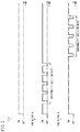
- FIG. 3 is a view for explaining the abnormality decision mode.
- FIG. 3 illustrates the fan motor 14 A as “fan motor A” and the fan motor 14 B as “fan motor B”.
- the abnormality decision mode of repeatedly switching between on and off of the power supply to the fan motor 14 A is executed.
- the abnormality decision mode is executed with respect to the fan motor 14 A
- the abnormality decision mode is not executed with respect to the fan motor 14 B.
- the abnormality decision mode is executed with respect to the fan motor 14 B.
- the abnormality decision mode is not executed with respect to the fan motor 14 A.
- the abnormality decision control unit 28 While the abnormality decision mode is executed with respect to the fan motor 14 A, the abnormality decision control unit 28 controls the rotational speed of the fan motor 14 B to be higher than the rotational speed before the abnormality decision mode is executed with respect to the fan motor 14 A. Similarly, while the abnormality decision mode is executed with respect to the fan motor 14 B, the abnormality decision control unit 28 controls the rotational speed of the fan motor 14 A to be higher than the rotational speed before the abnormality decision mode is executed with respect to the fan motor 14 B. With this arrangement, degradation of performance in cooling the CPU 16 or the like during execution of the abnormality decision mode with respect to one of the fan motors 14 can be compensated for by the other one of the fan motors 14 .
- the power supply to the fan motor 14 is repeatedly switched between off and on five times.
- the abnormality decision mode may be executed a plurality of times during the operation of the CPU 16 or may be performed only once.
- the abnormality decision mode may be executed every time the CPU 16 is activated or may be performed once in several times of activation of the CPU 16 .
- the present embodiment describes an example where the abnormality decision mode is executed with respect to the two fan motors 14 A, 14 B. Even when the abnormality decision mode is executed with respect to three or more fan motors, the abnormality decision mode may be executed with respect to one fan motor at a time, and the abnormality decision mode may not be executed with respect to the other fan motors.
- FIG. 4 is a flowchart illustrating abnormality decision control of the fan motors 14 .
- FIG. 4 illustrates the fan motor 14 A as the “fan motor A”, and the fan motor 14 B as the “fan motor B”.
- step S 1 the fan motor 14 A is judged if it has just been replaced (if it is controlled to be driven for the first time after the replacement). If the fan motor 14 A has just been replaced, the flow moves to step S 2 . If not, the flow goes to step S 3 .
- step S 2 a predetermined time and a predetermined rotational speed to be used for judgement of abnormality of the fan motor 14 A are set, and the flow moves to step S 3 .
- the predetermined time and the predetermined rotational speed indicate the predetermined time T 1 and the predetermined rotational speed N 1 in FIG. 2A .
- the setting of the predetermined time and the predetermined rotational speed will be described in detail below with reference to FIGS. 5 and 6 .
- step S 3 the fan motor 14 B is judged if it has just been replaced (if it is controlled to be driven for the first time after the replacement). If the fan motor 14 B has just been replaced, the flow moves to step S 4 . If not, the flow moves to step S 5 . In step S 4 , a predetermined time and a predetermined rotational speed to be used for judgement of abnormality of the fan motor 14 B are set, and the flow moves to step S 5 .
- step S 5 a judgement result of previous step S 6 is confirmed if the fan motor 14 A is judged to be normal. If the fan motor 14 A was judged as normal or has just been replaced, the flow moves to step S 6 . When the fan motor 14 A was judged as abnormal, the flow moves to step S 7 . In step S 6 , abnormality decision processing is performed with respect to the fan motor 14 A, and the flow moves to step S 7 .
- step S 7 a judgement result of previous step S 8 is confirmed if the fan motor 14 B is judged to be normal.
- the flow moves to step S 8 . If the fan motor 14 B was judged as abnormal, the flow moves to step S 5 .
- step S 8 the abnormality decision processing is performed with respect to the fan motor 14 B, and the flow moves to step S 5 .
- the abnormality decision processing with respect to the fan motors 14 A, 14 B will be described in detail below with reference to FIG. 7 .
- the fan motors 14 are designed to drive at a predetermined rated rotational speed when power at a rated current and a rated voltage is supplied.
- the predetermined time and the predetermined rotational speed used for abnormality decision with respect to the fan motors 14 are given in advance based on the fan motors 14 as designed. However, even at the shipment of the fan motors 14 from manufacturers, performance varies depending on the products or degrades due to long-term storage. Some of the fan motors 14 are incapable of sufficiently exhibiting expected performance even immediately after replacement. Hence, in the present embodiment, the predetermined time and the predetermined rotational speed used for abnormality decision with respect to the fan motor 14 are compensated per fan motor 14 .
- FIG. 5 is a flowchart illustrating the setting process of the predetermined time and the predetermined rotational speed.
- FIG. 6 is a view illustrating a relationship among a first rotational speed threshold, a second rotational speed threshold and a third rotational speed threshold, and a rated rotational speed used by the setting process of the predetermined time and the predetermined rotational speed.
- the same setting process of the predetermined time and the predetermined rotational speed is applied to both of the fan motors 14 A, 14 B.
- the setting processing of the predetermined time and the predetermined rotational speed used for the abnormality decision with respect to the fan motor 14 A will be described.
- the predetermined time and the predetermined rotational speed used for judgement of the abnormality of the fan motor 14 A are set according to a steady rotational speed of the fan motor 14 A driven at a rated voltage.
- the steady rotational speed is the average value of the rotational speed values measured approximately 100 times in a steady state where the rotational speed that has been changed since the fan motor 14 A was powered on becomes stable after passage of a certain period of time.
- step S 11 the steady rotational speed of the fan motor 14 A is judged if it is smaller than the first rotational speed threshold and equal to or greater than the second rotational speed threshold.
- the flow moves to step S 12 .
- the steady rotational speed of the fan motor 14 A is equal to or greater than the first rotational speed threshold, or less than the second rotational speed threshold, the flow moves to step S 13 .
- the first rotational speed threshold is set to be a rotational speed lower than the rated rotational speed of the fan motor 14 A, and is set to, for example, a rotational speed that is ⁇ 1[%] of the rated rotational speed of the fan motor 14 A.
- the second rotational speed threshold is a rotational speed smaller than the first rotational speed threshold, and is set to, for example, a rotational speed that is ⁇ 4[%] of the rated rotational speed of the fan motor 14 A (see FIG. 6 ).
- step S 12 the predetermined time is set longer than a preset time (or the predetermined rotational speed is set lower than the preset rotational speed). Setting the predetermined time longer than the preset time or setting the predetermined rotational speed lower than the preset rotational speed is to set the value for judging abnormality of the fan motor 14 A less strictly (less likely to be judged as abnormal). This is because the steady rotational speed of the fan motor 14 A that is slightly lower than the rated rotational speed has little influence on the performance for cooling the CPU 16 and the like, a rotation portion such as a bearing of the fan motor 14 A would not be worn much and a long operational life of the fan motor 14 A would be expectable.
- step S 13 the steady rotational speed of the fan motor 14 A is judged whether to be less than the second rotational speed threshold or not.
- the flow moves to step S 15 .
- the rated rotational speed of the fan motor 14 A is the second rotational speed threshold or more, the flow moves to step S 14 .
- step S 14 the steady rotational speed of the fan motor 14 A is judged to be greater than the third rotational speed threshold.
- the flow moves to step S 15 .
- the steady rotational speed of the fan motor 14 A is less than the third rotational speed threshold, the flow moves to step S 16 .
- the third rotational speed threshold is a rotational speed higher than the rated rotational speed of the fan motor 14 A, and is set to, for example, a rotational speed that is +1[%] of the rated rotational speed of the fan motor 14 A (see FIG. 6 ).
- step S 15 the predetermined time is set shorter than the preset time (or the predetermined rotational speed is set higher than the preset rotational speed). Setting the predetermined time shorter than the preset time or setting the predetermined rotational speed higher than the preset rotational speed is to set the value for judging abnormality of the fan motor 14 A more strictly (more likely to be judged as abnormal). This is because the steady rotational speed of the fan motor 14 A is far lower than the rated rotational speed, the rotation portion such as a bearing of the fan motor 14 A is in bad condition, grease starts to be solidified at the rotation portion, the long operational life of the fan motor 14 cannot be expected, and therefore an operator is encouraged to quickly prepare a replacement.
- step S 16 the predetermined time and the predetermined rotational speed are set to normal values (preset values), and processing is finished.
- the rated voltage and the rated rotational speed described herein may be replaced with a predetermined reference voltage and reference rotational speed different from the rated voltage and the rated rotational speed.
- FIG. 7 is a flowchart illustrating a process of making a decision on the abnormality of the fan motor 14 .
- the same abnormality decision processing is performed on both of the fan motors 14 A, 14 B. Only the abnormality decision processing with respect to the fan motor 14 A will be described.
- step S 21 a variable m and a variable n are reset (0 is substituted in the variable m and the variable n), and the flow moves to step S 22 .
- step S 22 the fan motor 14 A is powered off, and the flow moves to step S 23 .
- step S 23 the fan motor 14 A is powered on, and the flow moves to step S 24 .
- step S 24 a timer is started, and the flow moves to step S 25 .
- step S 25 an elapsed time T after the timer starts (the fan motor 14 A is powered on) is judged whether to reach the predetermined time or not.
- the flow moves to step S 26 .
- processing in step S 25 is repeated to stand by.
- step S 26 the rotational speed N of the fan motor 14 A is judged whether to be equal to or greater than the predetermined rotational speed.
- the rotational speed N of the fan motor 14 A is the predetermined rotational speed or more, the flow moves to step S 27 .
- the rotational speed N of the fan motor 14 A is less than the predetermined rotational speed, the flow moves to step S 30 .
- step S 27 the variable m is incremented, and the flow moves to step S 28 .
- step S 28 the variable m is judged whether it is “5” or not. When the variable m is “5”, the flow moves to step S 29 . When the variable m is not “5”, the flow returns to step S 22 .
- the power supply to the fan motor 14 A is repeatedly switched between off and on five times. Therefore, in step S 28 , the variable m is judged if it is “5”.
- the number of times to repeatedly switch between off and on of the power supply to the fan motor 14 A during the one abnormality decision mode may be arbitrarily set, and the condition in step S 28 may be set according to the set number of switching.
- step S 29 the fan motor 14 A is determined to be normal, and the processing is finished.
- step S 30 the variable n is incremented, and the flow moves to step S 31 .
- step S 31 the variable n is judged whether it is “3”. When the variable n is “3”, the flow moves to step S 32 . When the variable n is not “3”, the flow moves to step S 27 .
- the fan motor 14 A is determined to be abnormal provided that the condition of step S 26 is not satisfied at least three times while the power supply to the fan motor 14 A is repeatedly switched between off and on five times. Therefore, in step S 31 , the variable n is judged whether it is “3”.
- the number of times that the condition of step S 26 is not satisfied may be arbitrary set, and a condition of step S 31 may be set according to the set number of times.
- step S 32 the fan motor 14 A is decided as abnormal, and the flow moves to step S 33 .
- step S 33 the notification unit 22 notifies the abnormality to the operator, and the flow moves to step S 34 .
- step S 34 execution of the abnormality decision mode with respect to the fan motor 14 A is prevented, and the processing is finished.
- the abnormality decision control unit 28 controls the rotational speed of the fan motor 14 A to become higher than a rotational speed before the fan motor 14 A was judged to be as abnormal. Consequently, when dust adheres to the fan motor 14 A, it is possible to blow the dust away by increasing the rotational speed of the fan motor 14 to, return the fan motor 14 into a normal state.
- the abnormality decision control unit 28 controls the rotational speed of the fan motor 14 B to be higher than a rotational speed before the fan motor 14 A was judged to be as abnormal.
- the other fan motor 14 B can make up for lowered performance for cooling the CPU 16 or the like caused by the abnormality of the one fan motor 14 A.
- the fan motor control unit 26 normally controls the fan motor 14 B.
- the replacement judgement unit 30 has unique identification numbers of the fan motor 14 A and the fan motor 14 B, respectively.
- the identification numbers may be input to the replacement judgement unit 30 through an unillustrated input unit.
- the processing (the compensation process of compensating the predetermined time and the predetermined rotational speed) in step S 1 to step S 4 illustrated in FIG. 4 is performed. This compensation process of compensating the predetermined time and the predetermined rotational speed may not be performed.
- the abnormality decision processing with respect to the fan motor A (or the fan motor B) is carried out in current processing only when the previous processing determined that the fan motor 14 A (or the fan motor 14 B) is normal. However, even after the fan motor 14 A (or the fan motor 14 B) is determined as abnormal, the abnormality decision processing may be performed.
- the replacement judgement unit 30 may judge that the fan motor 14 A and the fan motor 14 B have been replaced in the following manner. For example, in case where after the abnormality decision control unit 28 had determined the fan motor 14 A as abnormal, the numerical control device (CPU 16 ) was turned off, and then turned on, if the abnormality decision control unit 28 does not judge the fan motor 14 A as abnormal, the replacement judgement unit 30 decides that the fan motor 14 A has been replaced.
- the abnormality decision with respect to the fan motor 14 is performed when the power supply to the fan motor 14 is switched from off to on or from on to off. Particularly when the power supply to the fan motor 14 is switched from off to on, the fan motor 14 is driven from a stop state. Therefore, static friction significantly influences on the rise of the rotational speed of the fan motor 14 , so that it is easy to find abnormality of the fan motor 14 .
- the power supply to the fan motor 14 is switched from off to on when the CPU 16 or the like is activated, or the power supply to the fan motor 14 is switched from on to off after the CPU 16 or the like is stopped.
- the power supply to the fan motor 14 is switched from off to on or from on to off only at a few occasions, providing limited opportunities to determine abnormality of the fan motor 14 . Therefore, it has been difficult to improve abnormality decision control with respect to the fan motor 14 . Even when there is a state where the fan motor 14 is supposed to be abnormal during the operation of the CPU 16 , it is not possible to determine if the fan motor 14 is abnormal during the operation of the fan motor 14 .
- the fan motor control device 10 that controls driving of the fan motor 14 A that cools the CPU 16 (a device that generates heat during the operation) includes the rotational speed sensor (rotational speed detecting unit) 20 A that detects the rotational speed of the fan motor 14 A, and the abnormality decision control unit 28 that executes the abnormality decision mode of repeatedly switching between on and off of the power supply to the fan motor 14 A during the operation of the CPU 16 , and determines abnormality of the fan motor 14 A based on the rotational speed of the fan motor 14 A during execution of the abnormality decision mode.
- the rotational speed sensor rotational speed detecting unit
- the abnormality decision control unit 28 can judge abnormality of the fan motor 14 A plural times even during the operation of the CPU 16 . Therefore, it is possible to improve abnormality decision accuracy with respect to the fan motor 14 A. Further, it is possible to determine the abnormality of the fan motor 14 A during the operation of the CPU 16 , and detect the abnormality of the fan motor 14 A at an early stage.
- the abnormality decision control unit 28 decides the fan motor 14 A as abnormal.
- the abnormality decision control unit 28 detects the set number of times that the rotational speed of the fan motor 14 A fails to reach the preset predetermined rotational speed within the preset predetermined time after the fan motor 14 A is powered on during the execution of the abnormality decision mode, the abnormality decision control unit 28 determines that the fan motor 14 A is abnormal. With this arrangement, it is possible to reduce a risk that the fan motor 14 A is erroneously determined as abnormal, so that the abnormality decision accuracy with respect to the fan motor 14 A can be improved.
- the abnormality decision control unit 28 compensates the predetermined time and the predetermined rotational speed used for abnormality decision.
- the steady rotational speed in a case of power supply of the rated voltage (predetermined reference voltage) to the fan motor 14 A is smaller than the first rotational speed threshold that is a rotational speed lower than the rated rotational speed (predetermined reference rotational speed) and is equal to or more than the second rotational speed threshold that is the rotational speed smaller than the first rotational speed threshold
- the abnormality decision control unit 28 sets the predetermined time to be longer than the preset time or sets the predetermined rotational speed to be lower than the preset rotational speed.
- the abnormality decision control unit 28 sets the predetermined time to be shorter than the preset time or sets the predetermined rotational speed to be higher than the preset rotational speed.
- the abnormality decision control unit 28 compensates the predetermined time and the predetermined rotational speed to be used for the abnormality decision.
- the steady rotational speed in a case of the power supply of the rated voltage (predetermined reference voltage) to the fan motor 14 A is greater than the third rotational speed threshold that is the rotational speed higher than the predetermined reference rotational speed
- the abnormality decision control unit 28 sets the predetermined time to be shorter than the preset time or sets the predetermined rotational speed to be higher than the preset rotational speed.
- the fan motor control device 10 includes the replacement judgement unit 30 that judges that the fan motor 14 A has been replaced.
- the abnormality decision control unit 28 determines that the fan motor 14 A is abnormal
- the abnormality decision control unit 28 controls the fan motor 14 B other than the fan motor 14 A at a higher rotational speed compared to that before the determination of abnormality of the fan motor 14 A. Consequently, the fan motor 14 B can make up for the degradation of performance in cooling the CPU 16 and the like caused by the abnormality of the fan motor 14 A.
- the replacement judgement unit 30 judges that the fan motor 14 A has been replaced. To determine that the fan motor 14 A has been replaced, the replacement judgement unit 30 may read an individual identification number of the fan motor 14 A. However, hardware that reads the individual identification numbers needs to be added and is concerned to lead to an increase in cost. In contrast, by determining that the fan motor 14 A has been replaced as described above, it is not necessary to add the hardware, and it is possible to suppress an increase in cost.
- the fan motor control device 10 includes the notification unit 22 that notifies an abnormality when the abnormality decision control unit 28 determines the fan motor 14 A as abnormal. After the notification unit 22 notifies the abnormality, the abnormality decision control unit 28 prevents the abnormality decision mode from being executed with respect to the fan motor 14 A determined as abnormal.
- a large torque is required to drive the fan motor 14 A from a stop state compared to a torque at a steady rotation. Once the fan motor 14 A determined as abnormal is stopped, the fan motor 14 A may not be driven again. The fan motor 14 A determined as abnormal is avoided from being stopped by the abnormality decision mode, so that it is possible to reduce the possibility that the fan motor 14 A is not driven again.
- the abnormality decision control unit 28 determines that the fan motor 14 A is abnormal, the abnormality decision control unit 28 controls the fan motor 14 A at a rotational speed higher than a rotational speed before the determination of the abnormality of the fan motor 14 A.
- the abnormality decision control unit 28 executes the abnormality decision mode with respect to one fan motor 14 A among a plurality of fan motors 14 A, 14 B, and does not simultaneously execute the abnormality decision mode with respect to the plurality of fan motors 14 A, 14 B. Therefore, the performance in cooling the CPU 16 can be prevented from lowering.
- the abnormality decision control unit 28 While executing the abnormality decision mode with respect to one fan motor 14 A among the plurality of fan motors 14 A, 14 B, the abnormality decision control unit 28 controls the other fan motor 14 B at a rotational speed higher than the rotational speed before the abnormality decision mode is executed with respect to the one fan motor 14 A. Consequently, the other fan motor 14 B can make up for the degradation in the performance in cooling the CPU 16 or the like caused when the abnormality decision mode is being executed with respect to the one fan motor 14 A.
- the abnormality decision with respect to the fan motor 14 in a case where the power supply to the fan motor 14 is switched from on to off can be also performed in the substantially same manner.
- the processing of setting the predetermined time and the predetermined rotational speed used for the abnormality decision with respect to the fan motor 14 in step S 12 illustrated in FIG. 5 as “setting the predetermined time longer than the preset time (or setting the predetermined rotational speed lower than the preset rotational speed).” should be replaced with “setting the predetermined time shorter than the preset time (or setting the predetermined rotational speed lower than the preset rotational speed).”
Landscapes
- Engineering & Computer Science (AREA)
- Mechanical Engineering (AREA)
- General Engineering & Computer Science (AREA)
- Power Engineering (AREA)
- Microelectronics & Electronic Packaging (AREA)
- Physics & Mathematics (AREA)
- General Physics & Mathematics (AREA)
- Control Of Electric Motors In General (AREA)
- Control Of Positive-Displacement Air Blowers (AREA)
Abstract
Description
Claims (15)
Applications Claiming Priority (2)
| Application Number | Priority Date | Filing Date | Title |
|---|---|---|---|
| JP2016-237200 | 2016-12-07 | ||
| JP2016237200A JP6557205B2 (en) | 2016-12-07 | 2016-12-07 | Fan motor control device |
Publications (2)
| Publication Number | Publication Date |
|---|---|
| US20180156225A1 US20180156225A1 (en) | 2018-06-07 |
| US10876537B2 true US10876537B2 (en) | 2020-12-29 |
Family
ID=62163872
Family Applications (1)
| Application Number | Title | Priority Date | Filing Date |
|---|---|---|---|
| US15/833,588 Active 2038-09-27 US10876537B2 (en) | 2016-12-07 | 2017-12-06 | Fan motor control device |
Country Status (4)
| Country | Link |
|---|---|
| US (1) | US10876537B2 (en) |
| JP (1) | JP6557205B2 (en) |
| CN (1) | CN108169672B (en) |
| DE (1) | DE102017011220B4 (en) |
Families Citing this family (13)
| Publication number | Priority date | Publication date | Assignee | Title |
|---|---|---|---|---|
| JPWO2015186208A1 (en) * | 2014-06-04 | 2017-04-20 | 東芝三菱電機産業システム株式会社 | Power equipment |
| JP7012222B2 (en) * | 2016-09-14 | 2022-01-28 | パナソニックIpマネジメント株式会社 | Motor control device |
| JP6380628B1 (en) * | 2017-07-31 | 2018-08-29 | 株式会社安川電機 | Power conversion apparatus, server, and data generation method |
| DE102018211850A1 (en) * | 2018-07-17 | 2020-01-23 | Ziehl-Abegg Se | Method for evaluating the operational readiness of an electric motor and electric motor and fan |
| JP7272766B2 (en) * | 2018-09-13 | 2023-05-12 | ミネベアミツミ株式会社 | blower |
| US11835055B2 (en) * | 2020-02-26 | 2023-12-05 | Fanuc Corporation | Fan control device and setting method |
| US11314612B2 (en) * | 2020-05-07 | 2022-04-26 | Dell Products, L.P. | System and methods for intelligent fan identification including fan quantity change detecting during POST |
| CN111946653A (en) * | 2020-08-27 | 2020-11-17 | 英业达科技有限公司 | Fan management method and system and server |
| TWI795182B (en) * | 2020-12-29 | 2023-03-01 | 建準電機工業股份有限公司 | Fan automatic detection system and fan automatic detection method |
| TWI762122B (en) * | 2020-12-29 | 2022-04-21 | 建準電機工業股份有限公司 | Fan automatic detection system and fan automatic detection method |
| TWI793985B (en) * | 2020-12-29 | 2023-02-21 | 建準電機工業股份有限公司 | Fan automatic detection system |
| KR20230000230A (en) * | 2021-06-24 | 2023-01-02 | 엘지전자 주식회사 | control method of a refrigerator |
| US20250389275A1 (en) * | 2024-06-24 | 2025-12-25 | Milwaukee Electric Tool Corporation | Blower with improved performance using power |
Citations (14)
| Publication number | Priority date | Publication date | Assignee | Title |
|---|---|---|---|---|
| JPH05187392A (en) | 1992-01-10 | 1993-07-27 | Toshiba Corp | Abnormality detecting device of fan motor for combustion |
| US5610594A (en) * | 1989-03-20 | 1997-03-11 | Papst Licensing Gmbh | Frequency monitoring device |
| JP2000166272A (en) | 1998-11-30 | 2000-06-16 | Canon Inc | Motor control device and method for detecting abnormal motor operation of motor control device |
| DE10040440A1 (en) | 2000-08-18 | 2002-03-07 | Rittal Electronic Systems Gmbh | Method and device for speed control of DC fans |
| US6400113B1 (en) * | 2000-07-19 | 2002-06-04 | International Business Machines Corporation | Apparatus and method for monitoring fan speeds within a computing system |
| CN1747319A (en) | 2004-09-07 | 2006-03-15 | 三菱电机株式会社 | Electric Power Steering Control |
| JP2008208806A (en) | 2007-02-27 | 2008-09-11 | Nec Corp | Fan failure diagnosis device, method and program |
| CN101675250A (en) | 2007-05-22 | 2010-03-17 | 大金工业株式会社 | Fan control system and air conditioner equipped with same |
| CN104052348A (en) | 2013-03-14 | 2014-09-17 | 发那科株式会社 | Control system for synchronous motor with abnormality detection and diagnosis function |
| CN104584423A (en) | 2013-08-12 | 2015-04-29 | 日本精工株式会社 | Motor control device, electric power steering device using same, and vehicle |
| JP2015108468A (en) | 2013-12-04 | 2015-06-11 | パナソニックIpマネジメント株式会社 | Fan filter unit and control system for fan filter unit |
| CN104967364A (en) | 2015-07-13 | 2015-10-07 | 中国恩菲工程技术有限公司 | Motor control device and method |
| JP2016115641A (en) | 2014-12-18 | 2016-06-23 | スタンレー電気株式会社 | Vehicular lighting unit |
| US20190293076A1 (en) * | 2018-03-26 | 2019-09-26 | In Win Development, Inc. | Control method for adjusting rotating speed of multiple fans according to temperature |
-
2016
- 2016-12-07 JP JP2016237200A patent/JP6557205B2/en active Active
-
2017
- 2017-12-05 DE DE102017011220.7A patent/DE102017011220B4/en active Active
- 2017-12-06 US US15/833,588 patent/US10876537B2/en active Active
- 2017-12-07 CN CN201711287096.4A patent/CN108169672B/en active Active
Patent Citations (16)
| Publication number | Priority date | Publication date | Assignee | Title |
|---|---|---|---|---|
| US5610594A (en) * | 1989-03-20 | 1997-03-11 | Papst Licensing Gmbh | Frequency monitoring device |
| JPH05187392A (en) | 1992-01-10 | 1993-07-27 | Toshiba Corp | Abnormality detecting device of fan motor for combustion |
| JP2000166272A (en) | 1998-11-30 | 2000-06-16 | Canon Inc | Motor control device and method for detecting abnormal motor operation of motor control device |
| US6400113B1 (en) * | 2000-07-19 | 2002-06-04 | International Business Machines Corporation | Apparatus and method for monitoring fan speeds within a computing system |
| DE10040440A1 (en) | 2000-08-18 | 2002-03-07 | Rittal Electronic Systems Gmbh | Method and device for speed control of DC fans |
| CN1747319A (en) | 2004-09-07 | 2006-03-15 | 三菱电机株式会社 | Electric Power Steering Control |
| JP2008208806A (en) | 2007-02-27 | 2008-09-11 | Nec Corp | Fan failure diagnosis device, method and program |
| CN102384100A (en) | 2007-05-22 | 2012-03-21 | 大金工业株式会社 | Fan control system |
| CN101675250A (en) | 2007-05-22 | 2010-03-17 | 大金工业株式会社 | Fan control system and air conditioner equipped with same |
| US8773048B2 (en) * | 2007-05-22 | 2014-07-08 | Daikin Industries, Ltd. | Fan control system and air conditioner that includes the same |
| CN104052348A (en) | 2013-03-14 | 2014-09-17 | 发那科株式会社 | Control system for synchronous motor with abnormality detection and diagnosis function |
| CN104584423A (en) | 2013-08-12 | 2015-04-29 | 日本精工株式会社 | Motor control device, electric power steering device using same, and vehicle |
| JP2015108468A (en) | 2013-12-04 | 2015-06-11 | パナソニックIpマネジメント株式会社 | Fan filter unit and control system for fan filter unit |
| JP2016115641A (en) | 2014-12-18 | 2016-06-23 | スタンレー電気株式会社 | Vehicular lighting unit |
| CN104967364A (en) | 2015-07-13 | 2015-10-07 | 中国恩菲工程技术有限公司 | Motor control device and method |
| US20190293076A1 (en) * | 2018-03-26 | 2019-09-26 | In Win Development, Inc. | Control method for adjusting rotating speed of multiple fans according to temperature |
Also Published As
| Publication number | Publication date |
|---|---|
| CN108169672B (en) | 2021-03-16 |
| DE102017011220A1 (en) | 2018-06-07 |
| US20180156225A1 (en) | 2018-06-07 |
| JP2018093677A (en) | 2018-06-14 |
| DE102017011220B4 (en) | 2024-12-19 |
| JP6557205B2 (en) | 2019-08-07 |
| CN108169672A (en) | 2018-06-15 |
Similar Documents
| Publication | Publication Date | Title |
|---|---|---|
| US10876537B2 (en) | Fan motor control device | |
| US9057378B2 (en) | Intelligent air moving apparatus | |
| CA2590792C (en) | Load drive controller and control system | |
| CN106227313A (en) | The duty of a kind of DC radiation fan determines method and device | |
| KR20080083696A (en) | System and method for monitoring motor load | |
| WO2018043754A1 (en) | Vehicular lamp fitting control device | |
| US20160160782A1 (en) | Method of diagnosing electronic water pump of engine | |
| US20160107863A1 (en) | Elevator motor cooling assembly | |
| JP7192952B1 (en) | Motor cooling system and motor cooling monitoring method | |
| US6321029B1 (en) | DC fan having a power sleep-mode control unit and method for controlling the same | |
| JP4633324B2 (en) | Motor control method | |
| JP5895185B2 (en) | Electric tool | |
| JP3661007B2 (en) | Outdoor fan control device | |
| JP2003124414A (en) | Electronic device fan control device | |
| CN107615645A (en) | Control device of electric motor | |
| JP5173889B2 (en) | Refrigerator control device | |
| KR101988980B1 (en) | Control method of cooling fan motor | |
| CN119508246B (en) | A server and its heat dissipation system | |
| JP6642033B2 (en) | Power supply for vacuum pump | |
| KR101595055B1 (en) | Abnomal state detecting apparatus for AC fan unit of a clean room | |
| JP2020205709A (en) | Motor system | |
| JP2001212391A (en) | Control device for sewing machine motor | |
| JP2005102914A (en) | Drive control device for sewing motor | |
| JP2005090912A (en) | Refrigerator control device | |
| KR100484187B1 (en) | Method and apparatus for discriminating operating status of laser beam printer |
Legal Events
| Date | Code | Title | Description |
|---|---|---|---|
| AS | Assignment |
Owner name: FANUC CORPORATION, JAPAN Free format text: ASSIGNMENT OF ASSIGNORS INTEREST;ASSIGNOR:IZUMI, RYOSUKE;REEL/FRAME:044318/0847 Effective date: 20171108 |
|
| FEPP | Fee payment procedure |
Free format text: ENTITY STATUS SET TO UNDISCOUNTED (ORIGINAL EVENT CODE: BIG.); ENTITY STATUS OF PATENT OWNER: LARGE ENTITY |
|
| STPP | Information on status: patent application and granting procedure in general |
Free format text: DOCKETED NEW CASE - READY FOR EXAMINATION |
|
| STPP | Information on status: patent application and granting procedure in general |
Free format text: NON FINAL ACTION MAILED |
|
| STPP | Information on status: patent application and granting procedure in general |
Free format text: NON FINAL ACTION MAILED |
|
| STPP | Information on status: patent application and granting procedure in general |
Free format text: RESPONSE TO NON-FINAL OFFICE ACTION ENTERED AND FORWARDED TO EXAMINER |
|
| STPP | Information on status: patent application and granting procedure in general |
Free format text: NOTICE OF ALLOWANCE MAILED -- APPLICATION RECEIVED IN OFFICE OF PUBLICATIONS |
|
| STCF | Information on status: patent grant |
Free format text: PATENTED CASE |
|
| MAFP | Maintenance fee payment |
Free format text: PAYMENT OF MAINTENANCE FEE, 4TH YEAR, LARGE ENTITY (ORIGINAL EVENT CODE: M1551); ENTITY STATUS OF PATENT OWNER: LARGE ENTITY Year of fee payment: 4 |