US10870370B2 - Vehicle seat - Google Patents
Vehicle seat Download PDFInfo
- Publication number
- US10870370B2 US10870370B2 US16/172,445 US201816172445A US10870370B2 US 10870370 B2 US10870370 B2 US 10870370B2 US 201816172445 A US201816172445 A US 201816172445A US 10870370 B2 US10870370 B2 US 10870370B2
- Authority
- US
- United States
- Prior art keywords
- backrest
- vehicle seat
- locking
- adjusting device
- displaced position
- Prior art date
- Legal status (The legal status is an assumption and is not a legal conclusion. Google has not performed a legal analysis and makes no representation as to the accuracy of the status listed.)
- Active, expires
Links
- 238000006073 displacement reaction Methods 0.000 claims abstract description 39
- 238000001514 detection method Methods 0.000 claims description 4
- 238000000034 method Methods 0.000 claims description 3
- 230000008901 benefit Effects 0.000 description 2
- 230000006835 compression Effects 0.000 description 2
- 238000007906 compression Methods 0.000 description 2
- 210000004705 lumbosacral region Anatomy 0.000 description 2
- 239000006096 absorbing agent Substances 0.000 description 1
- 230000000295 complement effect Effects 0.000 description 1
- 230000001419 dependent effect Effects 0.000 description 1
- 238000005516 engineering process Methods 0.000 description 1
- 230000011664 signaling Effects 0.000 description 1
- 239000000725 suspension Substances 0.000 description 1
- 238000004148 unit process Methods 0.000 description 1
Images


Classifications
-
- B—PERFORMING OPERATIONS; TRANSPORTING
- B60—VEHICLES IN GENERAL
- B60N—SEATS SPECIALLY ADAPTED FOR VEHICLES; VEHICLE PASSENGER ACCOMMODATION NOT OTHERWISE PROVIDED FOR
- B60N2/00—Seats specially adapted for vehicles; Arrangement or mounting of seats in vehicles
- B60N2/02—Seats specially adapted for vehicles; Arrangement or mounting of seats in vehicles the seat or part thereof being movable, e.g. adjustable
- B60N2/22—Seats specially adapted for vehicles; Arrangement or mounting of seats in vehicles the seat or part thereof being movable, e.g. adjustable the back-rest being adjustable
- B60N2/2222—Seats specially adapted for vehicles; Arrangement or mounting of seats in vehicles the seat or part thereof being movable, e.g. adjustable the back-rest being adjustable the back-rest having two or more parts
-
- B—PERFORMING OPERATIONS; TRANSPORTING
- B60—VEHICLES IN GENERAL
- B60N—SEATS SPECIALLY ADAPTED FOR VEHICLES; VEHICLE PASSENGER ACCOMMODATION NOT OTHERWISE PROVIDED FOR
- B60N2/00—Seats specially adapted for vehicles; Arrangement or mounting of seats in vehicles
- B60N2/02—Seats specially adapted for vehicles; Arrangement or mounting of seats in vehicles the seat or part thereof being movable, e.g. adjustable
- B60N2/0224—Non-manual adjustments, e.g. with electrical operation
- B60N2/0244—Non-manual adjustments, e.g. with electrical operation with logic circuits
- B60N2/0252—Non-manual adjustments, e.g. with electrical operation with logic circuits with relations between different adjustments, e.g. height of headrest following longitudinal position of seat
-
- B—PERFORMING OPERATIONS; TRANSPORTING
- B60—VEHICLES IN GENERAL
- B60N—SEATS SPECIALLY ADAPTED FOR VEHICLES; VEHICLE PASSENGER ACCOMMODATION NOT OTHERWISE PROVIDED FOR
- B60N2/00—Seats specially adapted for vehicles; Arrangement or mounting of seats in vehicles
- B60N2/02—Seats specially adapted for vehicles; Arrangement or mounting of seats in vehicles the seat or part thereof being movable, e.g. adjustable
- B60N2/0224—Non-manual adjustments, e.g. with electrical operation
- B60N2/0244—Non-manual adjustments, e.g. with electrical operation with logic circuits
- B60N2/0272—Non-manual adjustments, e.g. with electrical operation with logic circuits using sensors or detectors for detecting the position of seat parts
-
- B—PERFORMING OPERATIONS; TRANSPORTING
- B60—VEHICLES IN GENERAL
- B60N—SEATS SPECIALLY ADAPTED FOR VEHICLES; VEHICLE PASSENGER ACCOMMODATION NOT OTHERWISE PROVIDED FOR
- B60N2/00—Seats specially adapted for vehicles; Arrangement or mounting of seats in vehicles
- B60N2/02—Seats specially adapted for vehicles; Arrangement or mounting of seats in vehicles the seat or part thereof being movable, e.g. adjustable
- B60N2/04—Seats specially adapted for vehicles; Arrangement or mounting of seats in vehicles the seat or part thereof being movable, e.g. adjustable the whole seat being movable
- B60N2/14—Seats specially adapted for vehicles; Arrangement or mounting of seats in vehicles the seat or part thereof being movable, e.g. adjustable the whole seat being movable rotatable, e.g. to permit easy access
- B60N2/146—Seats specially adapted for vehicles; Arrangement or mounting of seats in vehicles the seat or part thereof being movable, e.g. adjustable the whole seat being movable rotatable, e.g. to permit easy access characterised by the locking device
-
- B—PERFORMING OPERATIONS; TRANSPORTING
- B60—VEHICLES IN GENERAL
- B60N—SEATS SPECIALLY ADAPTED FOR VEHICLES; VEHICLE PASSENGER ACCOMMODATION NOT OTHERWISE PROVIDED FOR
- B60N2/00—Seats specially adapted for vehicles; Arrangement or mounting of seats in vehicles
- B60N2/24—Seats specially adapted for vehicles; Arrangement or mounting of seats in vehicles for particular purposes or particular vehicles
- B60N2/26—Seats specially adapted for vehicles; Arrangement or mounting of seats in vehicles for particular purposes or particular vehicles for children
- B60N2/28—Seats readily mountable on, and dismountable from, existing seats or other parts of the vehicle
- B60N2/2851—Seats readily mountable on, and dismountable from, existing seats or other parts of the vehicle provided with head-rests
-
- B—PERFORMING OPERATIONS; TRANSPORTING
- B60—VEHICLES IN GENERAL
- B60N—SEATS SPECIALLY ADAPTED FOR VEHICLES; VEHICLE PASSENGER ACCOMMODATION NOT OTHERWISE PROVIDED FOR
- B60N2/00—Seats specially adapted for vehicles; Arrangement or mounting of seats in vehicles
- B60N2/24—Seats specially adapted for vehicles; Arrangement or mounting of seats in vehicles for particular purposes or particular vehicles
- B60N2/38—Seats specially adapted for vehicles; Arrangement or mounting of seats in vehicles for particular purposes or particular vehicles specially constructed for use on tractors or like off-road vehicles
-
- B—PERFORMING OPERATIONS; TRANSPORTING
- B60—VEHICLES IN GENERAL
- B60N—SEATS SPECIALLY ADAPTED FOR VEHICLES; VEHICLE PASSENGER ACCOMMODATION NOT OTHERWISE PROVIDED FOR
- B60N2/00—Seats specially adapted for vehicles; Arrangement or mounting of seats in vehicles
- B60N2/64—Back-rests or cushions
-
- B—PERFORMING OPERATIONS; TRANSPORTING
- B60—VEHICLES IN GENERAL
- B60N—SEATS SPECIALLY ADAPTED FOR VEHICLES; VEHICLE PASSENGER ACCOMMODATION NOT OTHERWISE PROVIDED FOR
- B60N2/00—Seats specially adapted for vehicles; Arrangement or mounting of seats in vehicles
- B60N2/80—Head-rests
- B60N2/806—Head-rests movable or adjustable
- B60N2/868—Head-rests movable or adjustable providing a lateral movement parallel to the occupant's shoulder line
-
- B—PERFORMING OPERATIONS; TRANSPORTING
- B60—VEHICLES IN GENERAL
- B60N—SEATS SPECIALLY ADAPTED FOR VEHICLES; VEHICLE PASSENGER ACCOMMODATION NOT OTHERWISE PROVIDED FOR
- B60N2/00—Seats specially adapted for vehicles; Arrangement or mounting of seats in vehicles
- B60N2/02—Seats specially adapted for vehicles; Arrangement or mounting of seats in vehicles the seat or part thereof being movable, e.g. adjustable
- B60N2002/0204—Seats specially adapted for vehicles; Arrangement or mounting of seats in vehicles the seat or part thereof being movable, e.g. adjustable characterised by the seat or seat part turning about or moving along a non-standard, particular axis, i.e. an axis different from the axis characterising the conventional movement
- B60N2002/022—Seats specially adapted for vehicles; Arrangement or mounting of seats in vehicles the seat or part thereof being movable, e.g. adjustable characterised by the seat or seat part turning about or moving along a non-standard, particular axis, i.e. an axis different from the axis characterising the conventional movement the seat or seat part turning about or moving along a vertical axis
-
- B60N2002/0272—
-
- B—PERFORMING OPERATIONS; TRANSPORTING
- B60—VEHICLES IN GENERAL
- B60N—SEATS SPECIALLY ADAPTED FOR VEHICLES; VEHICLE PASSENGER ACCOMMODATION NOT OTHERWISE PROVIDED FOR
- B60N2/00—Seats specially adapted for vehicles; Arrangement or mounting of seats in vehicles
- B60N2/90—Details or parts not otherwise provided for
- B60N2/919—Positioning and locking mechanisms
- B60N2002/948—Positioning and locking mechanisms the actuation of the positioning or locking mechanism for one seat part being dependent on the position of another seat part, e.g. the seats floor lock being unlocked when the back-rest is inclined or the backrest can be tilted only when the seat is in its rear position
-
- B—PERFORMING OPERATIONS; TRANSPORTING
- B60—VEHICLES IN GENERAL
- B60N—SEATS SPECIALLY ADAPTED FOR VEHICLES; VEHICLE PASSENGER ACCOMMODATION NOT OTHERWISE PROVIDED FOR
- B60N2205/00—General mechanical or structural details
- B60N2205/30—Seat or seat parts characterised by comprising plural parts or pieces
- B60N2205/35—Seat, bench or back-rests being split laterally in two or more parts
Definitions
- the invention relates to a vehicle seat having a backrest consisting of a backrest lower part and a backrest upper part which is displaceable relative to the backrest lower part.
- Such vehicle seats are known for example from DE 10 2011 055 895, wherein the backrest upper part is displaceable in a variety of ways relative to the backrest lower part.
- the core idea of the invention is to provide a vehicle seat with a backrest consisting of a backrest lower part and a backrest upper part, which is displaceable relative to the backrest lower part, the vehicle seat being connected to a rotary adjustment device for rotating the vehicle seat, and wherein the rotary adjustment device comprises a locking device for locking the rotary adjustment device wherein the backrest upper part and the locking device are connected to one another in such a way that when the backrest upper part is displaced relative to the backrest lower part from a non-displaced position to a displaced position, the locking of the rotary adjusting device may be released.
- the vehicle seat can simulate the rotation of the upper body.
- a rotation of the chest or shoulder region results on the seat in a rotational movement of the lumbar region, which can be tracked by the vehicle seat by means of a rotary adjusting device.
- the vehicle seat further comprises a seat part, wherein the backrest lower part is rigidly connected to the seat part.
- the movement of the seat part and the backrest lower part are the same, if provided.
- the locking means is provided with a locking element which may be contacted with the rotary adjustment device in order to lock or latch the rotary adjustment device, or may be released from the rotary adjustment device to unlock the rotary adjustment device.
- a first Bowden cable is provided, wherein a first end of the Bowden cable is connected to the backrest upper part and a second end of the Bowden cable is connected with the locking device such that in case of a displacement of the backrest portion from the non-displaced position into the displaced position, the first end of the Bowden cable may be displaced, whereby a pulling force or tension may be transmitted to the locking device and the locking of the rotary adjusting device may be released.
- the first end of the Bowden cable is connected to the backrest upper part in such a way that the first end of the Bowden cable is displaced with the displacement of the backrest upper part from the non-displaced position to the displaced position, whereby a pulling force or tension is transmitted to the Bowden cable via the first end.
- a holding device is provided, which is connected to both the Bowden cable, in particular in the region of the first end of the Bowden cable, and the backrest lower part. This means that the holding device is not displaced in case of a displacement of the backrest upper part relative to the backrest lower part.
- the first Bowden cable is a push-pull Bowden cable. This means that both tensile forces and compressive forces can be transmitted by means of the first Bowden cable. In particular, this means that when the backrest upper part is in the displaced position, the locking of the rotary adjusting device can be produced by displacing the backrest part from the displaced position into the non-displaced position.
- a second Bowden cable is provided, which is connected to the rotary adjusting device and to the backrest upper part and is provided and arranged in order to transfer the backrest upper part from the displaced position into the non-displaced position by rotation of the vehicle seat by the rotary adjusting device from a rotated position to a normal position of the vehicle seat.
- the backrest upper part can be brought from the non-displaced position to the displaced position by means of the first Bowden cable, wherein the locking of the rotary adjusting device is released, and by means of the second Bowden cable, the backrest upper part from the displaced position to the non-displaced position when the vehicle seat is transferred from the rotated into the unrotated position.
- the first Bowden cable is a Bowden cable which can transmit only tensile forces
- a return spring is connected to the second end of the Bowden cable, wherein by means of the return spring, the lock can be produced upon displacement of the backrest upper part from the displaced position into the non-displaced position.
- the return spring is preferably a compression spring or a torsion spring. In such springs, the spring is deformed when transmitting a pulling force or tension and it builds up a restoring force, which is directed against the pulling force or tension of the Bowden cable.
- a first sensor is provided, which is designed and provided to detect a displacement of the backrest upper part relative to the backrest lower part from a non-displaced position to a displaced position, wherein after detection of this displacement of the backrest upper part, the locking of the rotary adjusting device is releasable, and is designed and provided also to detect a displacement of the backrest upper part from the displaced position into the non-displaced position, wherein after this displacement, the locking of the rotary adjusting device can be obtained.
- the first sensor By means of the first sensor, it is therefore possible to detect the displacement of the backrest upper part, in each direction of displacement, that is, from the non-displaced position to the displaced position, and vice versa.
- an electronic control unit which is designed and provided to receive and process first signals of the first sensor, wherein starting and depending on the first signals of the first sensor, the electronic control unit may transmit a locking device control signal to an actuator unit, said actuator unit being provided and configured to actuate the locking device.
- the first sensor sends first signals, in particular to the electronic control unit, wherein the first signals contain information that a displacement of the backrest upper part has been detected.
- the electronic control unit processes these signals in a corresponding manner, in particular the control unit recognizes which type of displacement is involved, that is to say either a movement from the non-displaced position into the displaced position or from the displaced position into the non-displaced position.
- the locking device is actuated by the control unit, namely the lock of the rotary adjusting device is either released or generated.
- FIG. 1A is a view of a vehicle seat in accordance with embodiments of the present disclosure.
- FIG. 1B is another view of a vehicle seat in accordance with embodiments of the present disclosure.
- FIG. 2A is yet another view of a vehicle seat in accordance with embodiments of the present disclosure.
- FIG. 2AA is a detail from FIG. 2A and illustrates a connecting element in accordance with embodiments of the present disclosure
- FIG. 2B is another view in accordance with embodiments of the present disclosure.
- FIG. 2BB is a detail from FIG. 2B and illustrates a connecting element in accordance with embodiments of the present disclosure
- FIG. 3A is view of a locking device for locking a rotary adjusting device in accordance with embodiments of the present disclosure
- FIG. 3B is another view of a locking device for locking a rotary adjusting device in accordance with embodiments of the present disclosure
- FIG. 4 is a view of a vehicle seat in accordance with another embodiment of the present disclosure.
- FIG. 5A is a view of the locking device, showing the locking device in a locked state, in accordance with another embodiment of the present disclosure
- FIG. 5B is a view of the locking device, showing the locking device in an unlocked state, in accordance with another embodiment of the present disclosure
- FIG. 5C is a view of the locking device, showing perspective view of the rotary adjusting device, in accordance with another embodiment of the present disclosure
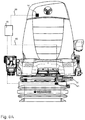
- FIG. 6A is a front view of a vehicle seat in accordance with an alternative the present disclosure.
- FIG. 6B is another view of a vehicle seat in accordance with the alternative the present disclosure.
- FIG. 1A shows a vehicle seat 1 which has a backrest 2 , wherein the backrest 2 has a backrest lower part 3 and a backrest upper part 4 .
- the backrest upper part is arranged to be displaceable relative to the backrest lower part 3 , in particular by means of a displacement device (not shown here).
- the backrest upper part 4 is arranged in a height direction H above the backrest lower part 3 .
- the vehicle seat 1 preferably has a seat part 17 , the seat part 17 being particularly preferably rigidly connected to one another. Rigid means here, however, that a rotation of the backrest 3 about a first pivot axis 18 is possible, whereby the inclination of the backrest 3 relative to the seat part 17 is adjustable.
- vehicle seat 1 is connected to a rotary adjusting device 5 , by means of which the vehicle seat 1 is rotatably mounted about a vertical axis 19 .
- a vehicle seat base structure 20 which may comprise, for example, a suspension and/or an absorber for suspending or cushioning the vehicle seat 1 .
- the vehicle seat 1 may be disposed and connected by means of the vehicle seat base structure 20 or, if no such vehicle seat base structure 20 is provided, by means of the rotary adjusting device 5 to a body 21 or a vehicle floor 21 .
- both a non-displaced position P 1 of the backrest upper part 4 and a normal position D 1 or unrotated position D 1 of the rotary adjusting device 5 are shown. This means that the vehicle seat 1 as a whole is not rotated either.
- the rotary adjusting device 5 is locked, in such a way that no rotation of the vehicle seat 1 is possible.
- FIG. 1B shows a displaced position P 2 of the backrest upper part 4 and a rotated position D 2 of the rotary adjusting device 5 . That is, the vehicle seat 1 is rotated about the vertical axis 19 .
- the vehicle seat 1 can follow the movement of the body of said person by means of the rotary adjusting device 5 .
- connection of the backrest upper part 4 and the locking device 6 and the locking device 6 are shown in various embodiments in more detail.
- FIG. 2A shows the vehicle seat 1 of FIG. 1A and FIG. 2B shows the vehicle seat 1 of FIG. 1B .
- a first Bowden cable 7 can be seen, with a first end 9 and a second end 10 .
- the first Bowden cable 7 in particular the first end 9 , is connected to the upper backrest part 4 , in such a way that when the backrest upper part 4 is displaced, represented by the arrow, a pulling force or tension is exerted on the first Bowden cable 7 .
- the second end 10 of the first Bowden cable 7 is connected to the locking device 6 of the rotary adjusting device 5 , wherein in the non-displaced position P 1 , the rotary adjusting device 5 is locked by means of locking device 6 , that is, no rotation of the vehicle seat 1 is possible.
- FIG. 2AA shows a detail of FIG. 2A in an enlargement.
- the first Bowden cable 7 is connected on the one hand by means of a first connecting element 22 with the backrest lower part 3
- the first end 9 of the first Bowden cable 7 is connected by means of a second connecting element 23 with the backrest upper part 4 .
- the first connection element 22 is arranged at a first distance 24 from the second connection element 23 .
- FIG. 2B shows the vehicle seat in the displaced position P 2 and in the rotated position D 2 .
- the second connecting element 23 is also displaced in accordance with the displacement of the backrest upper part 4 .
- the first distance 24 changes toward a second distance 25 , which is greater than the first distance 24 in case of a displacement from the non-displaced position P 1 to the displaced position P 2 .
- FIGS. 3A and 3B show a first embodiment of a locking device 6 for locking the rotary adjusting device 5 .
- the locking device 6 in this case comprises a lever element 26 , which is pivotable about a second pivot axis 27 .
- the lever element 26 also has a first end 28 and a second end 29 , wherein the first end 28 can be brought into contact with an opening 30 of the rotary adjusting device 5 , in particular a rotary adapter 31 , and the second end 29 is connected with the second end 10 of the first Bowden cable 7 .
- the lever element 26 can be pivoted about the second pivot axis 27 . This situation is shown in FIG. 3B .
- lever element 26 may be connected to a return spring 32 , wherein the return spring 32 may be formed as a torsion spring.
- the rotary adjusting device 5 is locked. If the first end 28 is not in contact with the opening 30 , as shown in FIG. 3B , the rotary adjusting device 5 is not locked.
- FIG. 4 shows a further embodiment of the vehicle seat 1 , wherein an additional second Bowden cable 8 is provided.
- This second Bowden cable 8 is connected on the one hand with the rotary adjusting device 5 and on the other hand with the backrest upper part 4 .
- the second Bowden cable 8 is suitable for bringing the backrest upper part 4 from the displaced position P 2 into the non-displaced position P 1 by rotating the vehicle seat 1 from the rotated position D 2 to the normal position D 1 .
- the second Bowden cable 8 as well has a first end 11 and a second end 12 , wherein the first end 11 is connected to the backrest upper part 4 and the second end 12 is connected with the rotary adjusting device 5 .
- a pulling force or tension is transmitted to the first end 11 via the second end 12 and the backrest upper part 4 is displaced from the displaced position P 2 to the non-displaced position P 1 .
- FIGS. 5A, 5B and 5C show a further embodiment of the locking device 6 , wherein the locking device 6 is formed as described in more detail below.
- the rotary adapter 6 or the rotary adjusting device 5 has a sprocket 34 , which is presently designed as an internal sprocket 34 .
- the rotary adapter 6 is rotatably mounted with respect to a rotating adapter base 37 by means of a ball bearing 36 with ball elements 35 .
- the locking device 6 has in particular a locking element 32 , which is designed such that the locking element 32 is formed complementary to the sprocket 34 .
- the locking element 32 preferably has three teeth 38 which can be brought into contact with corresponding tooth gaps 38 ′.
- the rotary adjusting device 6 is locked, as shown in FIG. 5A ; if the teeth 38 do not engage in the tooth gaps 38 ′, then the rotary adjusting device is unlocked, as shown in FIG. 5B .
- first Bowden cable 7 is connected with its first end 9 by means of a Bowden cable attachment 33 with the locking element 32 , and further a return spring 13 , in the present case designed as a compression spring, is also provided, which is in operative contact with the locking element 32 and the rotary adapter 5 .
- FIG. 5A shows the locking device 6 in a locked state
- FIG. 5B shows the locking device 6 in an unlocked state
- FIG. 5C shows a perspective view of the entire rotary adjusting device 5 with a locking device 6 .
- FIGS. 6A and 6B an alternative embodiment is shown, which does not include Bowden cables, whereas the locking device 6 is controlled electronically.
- a first sensor 14 is provided, which is designed and provided to detect a displacement of the backrest upper part 4 relative to the backrest lower part 3 from an non-displaced position P 1 to a displaced position P 2 , wherein after detection of this displacement of the backrest upper part 4 , the locking of the rotary adjusting device 5 is releasable by means of the locking device 6 , and to detect a displacement of the backrest upper part 4 from the displaced position P 2 into the non-displaced position P 1 , wherein after this displacement, the locking of the rotary adjusting device is obtained by means of the locking device 6 .
- an electronic control unit 15 is provided, which is designed and provided to receive and process first signals 39 of the first sensor 14 , wherein starting from the signals of the first sensor 14 , the electronic control unit 15 may transmit a locking device control signal 40 to an actuator unit 16 , wherein the actuator unit 16 is provided and configured to actuate the locking device 6 .
- the actuation of the locking device 6 by the actuator unit 16 depends on the type of displacement. If the backrest upper part 4 is displaced from the non-displaced position P 1 to the displaced position P 2 , then the locking device control signal 40 is sent with the information that the lock has to be released. If the seat back upper part 4 is displaced from the displaced position P 2 to the non-displaced position P 1 , the locking device control signal 40 is sent with the information that the lock has to be engaged.
- a locking which is only made when the rotary adjusting device 5 is in the normal position D 1 .
- a second sensor 42 may be provided, wherein the second sensor 41 is connected to the control unit 15 by signalling technology.
Landscapes
- Engineering & Computer Science (AREA)
- Aviation & Aerospace Engineering (AREA)
- Transportation (AREA)
- Mechanical Engineering (AREA)
- Health & Medical Sciences (AREA)
- Child & Adolescent Psychology (AREA)
- General Health & Medical Sciences (AREA)
- Seats For Vehicles (AREA)
- Chairs For Special Purposes, Such As Reclining Chairs (AREA)
Abstract
Description
- 1 vehicle seat
- 2 backrest
- 3 backrest lower part
- 4 backrest upper part
- 5 rotary adjustment device
- 6 locking device
- 7 first Bowden cable
- 8 second Bowden cable
- 9 first end of the first Bowden cable
- 10 second end of the first Bowden cable
- 11 first end of the second Bowden cable
- 12 second end of the second Bowden cable
- 13 return spring
- 14 first sensor
- 15 control unit
- 16 actuator unit
- 17 seat part
- 18 first pivot axis
- 19 vertical axis
- 20 vehicle seat base structure
- 21 body
- 22 first connecting element
- 23 second connecting element
- 24 first distance
- 25 second distance
- 26 lever element
- 27 second pivot axis
- 28 first end of the lever element
- 29 second end of the lever element
- 30 opening
- 31 rotation adapter
- 32 locking element
- 33 Bowden cable attachment
- 34 sprocket
- 35 ball element
- 36 ball bearing
- 37 rotating adapter base
- 38 tooth
- 38′ tooth gap
- 39 first signal
- 40 locking device control signal
- 41 second sensor
- P1 non-displaced position
- P2 displaced position
- D1 normal position
- D2 rotated position
- L longitudinal direction
- H height direction
- B width direction
Claims (8)
Applications Claiming Priority (3)
| Application Number | Priority Date | Filing Date | Title |
|---|---|---|---|
| DE102017125338 | 2017-10-27 | ||
| DE102017125338.6A DE102017125338B4 (en) | 2017-10-27 | 2017-10-27 | Vehicle seat |
| DE102017125338.6 | 2017-10-27 |
Publications (2)
| Publication Number | Publication Date |
|---|---|
| US20190126788A1 US20190126788A1 (en) | 2019-05-02 |
| US10870370B2 true US10870370B2 (en) | 2020-12-22 |
Family
ID=63965086
Family Applications (1)
| Application Number | Title | Priority Date | Filing Date |
|---|---|---|---|
| US16/172,445 Active 2039-02-01 US10870370B2 (en) | 2017-10-27 | 2018-10-26 | Vehicle seat |
Country Status (4)
| Country | Link |
|---|---|
| US (1) | US10870370B2 (en) |
| EP (1) | EP3480055B1 (en) |
| CN (1) | CN109720242B (en) |
| DE (1) | DE102017125338B4 (en) |
Families Citing this family (3)
| Publication number | Priority date | Publication date | Assignee | Title |
|---|---|---|---|---|
| JP7618920B2 (en) | 2021-04-02 | 2025-01-22 | トヨタ車体株式会社 | Vehicle seat device |
| US11718214B2 (en) | 2021-12-27 | 2023-08-08 | Lear Corporation | Modular seat with cable tensioning system |
| DE102023113920A1 (en) * | 2023-05-26 | 2024-11-28 | Grammer Aktiengesellschaft | vehicle seat with swivel device |
Citations (10)
| Publication number | Priority date | Publication date | Assignee | Title |
|---|---|---|---|---|
| US4802706A (en) * | 1985-06-04 | 1989-02-07 | Nippon Soken, Inc. | Rotary seat for vehicle |
| US5909926A (en) * | 1996-09-04 | 1999-06-08 | Hi-Tech Seating Products, Inc. | Vehicle seating assembly |
| DE102011055895A1 (en) | 2011-11-30 | 2013-06-06 | Grammer Ag | Vehicle seat with lateral support element |
| US20150015045A1 (en) * | 2013-06-26 | 2015-01-15 | Grammer Ag | Vehicle seat and utility motor vehicle comprising a vehicle seat |
| US20150015047A1 (en) * | 2013-06-26 | 2015-01-15 | Grammer Ag | Vehicle seat and utility motor vehicle comprising a vehicle seat |
| US20150015046A1 (en) * | 2013-06-26 | 2015-01-15 | Grammer Ag | Vehicle seat and utility motor vehicle comprising a vehicle seat |
| US20160039315A1 (en) * | 2014-06-03 | 2016-02-11 | Grammer Ag | Utility vehicle with lockable slide part |
| DE102014117101A1 (en) | 2014-11-21 | 2016-05-25 | Grammer Ag | Armrest assembly for a seat, in particular for a vehicle seat |
| DE102015212459A1 (en) | 2015-07-02 | 2017-01-05 | Hamm Ag | Seat for a construction machine, as well as construction machine |
| US20170297721A1 (en) * | 2016-04-15 | 2017-10-19 | Goodrich Corporation | Rotational brake assembly for a seat locking mechanism |
Family Cites Families (3)
| Publication number | Priority date | Publication date | Assignee | Title |
|---|---|---|---|---|
| JP5941222B1 (en) * | 2015-06-12 | 2016-06-29 | 備前発条株式会社 | Headrest |
| US9809131B2 (en) * | 2015-12-04 | 2017-11-07 | Ford Global Technologies, Llc | Anthropomorphic pivotable upper seatback support |
| CN107161042B (en) * | 2017-06-29 | 2023-06-30 | 长春富维安道拓汽车饰件系统有限公司 | Detachable automobile seat |
-
2017
- 2017-10-27 DE DE102017125338.6A patent/DE102017125338B4/en not_active Expired - Fee Related
-
2018
- 2018-10-19 EP EP18201422.5A patent/EP3480055B1/en active Active
- 2018-10-25 CN CN201811249933.9A patent/CN109720242B/en active Active
- 2018-10-26 US US16/172,445 patent/US10870370B2/en active Active
Patent Citations (11)
| Publication number | Priority date | Publication date | Assignee | Title |
|---|---|---|---|---|
| US4802706A (en) * | 1985-06-04 | 1989-02-07 | Nippon Soken, Inc. | Rotary seat for vehicle |
| US5909926A (en) * | 1996-09-04 | 1999-06-08 | Hi-Tech Seating Products, Inc. | Vehicle seating assembly |
| DE102011055895A1 (en) | 2011-11-30 | 2013-06-06 | Grammer Ag | Vehicle seat with lateral support element |
| US20130175837A1 (en) * | 2011-11-30 | 2013-07-11 | Grammer Ag | Vehicle seat with lateral support element |
| US20150015045A1 (en) * | 2013-06-26 | 2015-01-15 | Grammer Ag | Vehicle seat and utility motor vehicle comprising a vehicle seat |
| US20150015047A1 (en) * | 2013-06-26 | 2015-01-15 | Grammer Ag | Vehicle seat and utility motor vehicle comprising a vehicle seat |
| US20150015046A1 (en) * | 2013-06-26 | 2015-01-15 | Grammer Ag | Vehicle seat and utility motor vehicle comprising a vehicle seat |
| US20160039315A1 (en) * | 2014-06-03 | 2016-02-11 | Grammer Ag | Utility vehicle with lockable slide part |
| DE102014117101A1 (en) | 2014-11-21 | 2016-05-25 | Grammer Ag | Armrest assembly for a seat, in particular for a vehicle seat |
| DE102015212459A1 (en) | 2015-07-02 | 2017-01-05 | Hamm Ag | Seat for a construction machine, as well as construction machine |
| US20170297721A1 (en) * | 2016-04-15 | 2017-10-19 | Goodrich Corporation | Rotational brake assembly for a seat locking mechanism |
Non-Patent Citations (2)
| Title |
|---|
| Extended Search Report for European Patent Application No. 18201422.5, dated Apr. 5, 2019, 3 pages. |
| Official Action for German Patent Application No. 102017125338.6, dated Jun. 15, 2018, 3 pages. |
Also Published As
| Publication number | Publication date |
|---|---|
| DE102017125338A1 (en) | 2019-05-02 |
| EP3480055A1 (en) | 2019-05-08 |
| EP3480055B1 (en) | 2020-05-27 |
| DE102017125338B4 (en) | 2020-09-03 |
| CN109720242B (en) | 2021-07-27 |
| US20190126788A1 (en) | 2019-05-02 |
| CN109720242A (en) | 2019-05-07 |
Similar Documents
| Publication | Publication Date | Title |
|---|---|---|
| US10870370B2 (en) | Vehicle seat | |
| US5806932A (en) | Seat adjustment and dumping mechanism with memory of adjustment | |
| JP4656942B2 (en) | Vehicle door handle with inertial safety system | |
| US10688892B2 (en) | Child safety seat | |
| US10562425B2 (en) | Adjustment device for a headrest of a vehicle seat | |
| US9022436B2 (en) | Actuator arrangement for a vehicle door latch | |
| CN107152207B (en) | Improved door lock actuators, especially interior door lock actuators | |
| US6598912B2 (en) | Actuating device for a hood of a motor vehicle | |
| US9308835B2 (en) | Vehicle seat with at least one fitting and an actuating shaft | |
| CN106150236B (en) | Outside handle device for vehicle | |
| US10406946B2 (en) | Vehicle seat | |
| KR20140114046A (en) | Recliner for a vehicle seat and vehicle seat | |
| CN208347492U (en) | Operating system and motor vehicles for vehicle door | |
| WO2006020313A3 (en) | Vehicule seat back recliner and assembly | |
| CN113195855A (en) | Vehicle door handle | |
| KR20100030428A (en) | Lever typed seat arm rest angle adjusting device | |
| DE502006004027D1 (en) | BOWDENZUGANBINDING WITH INTEGRATED MASS LOCK | |
| EP0960763A3 (en) | Seat track with cam actuated locking device | |
| JP2002234369A (en) | Automotive seating equipment | |
| US20180201161A1 (en) | Vehicle slide rail device | |
| US9180797B2 (en) | Vehicle seat | |
| JP5227549B2 (en) | Vehicle seat | |
| EP1394344A1 (en) | Construction machine with door locking device | |
| CN111183057A (en) | Vehicle Seat with Easy Access Mechanism | |
| CN105658469B (en) | The locking indicator of seat, seat, the method for vehicle and locking of vehicle seat |
Legal Events
| Date | Code | Title | Description |
|---|---|---|---|
| FEPP | Fee payment procedure |
Free format text: ENTITY STATUS SET TO UNDISCOUNTED (ORIGINAL EVENT CODE: BIG.); ENTITY STATUS OF PATENT OWNER: LARGE ENTITY |
|
| AS | Assignment |
Owner name: GRAMMER AG, GERMANY Free format text: ASSIGNMENT OF ASSIGNORS INTEREST;ASSIGNOR:HALLER, THOMAS;REEL/FRAME:047440/0947 Effective date: 20181031 |
|
| AS | Assignment |
Owner name: GRAMMER AG, GERMANY Free format text: ASSIGNMENT OF ASSIGNORS INTEREST;ASSIGNOR:HALLER, THOMAS;REEL/FRAME:047546/0583 Effective date: 20181031 |
|
| STPP | Information on status: patent application and granting procedure in general |
Free format text: APPLICATION DISPATCHED FROM PREEXAM, NOT YET DOCKETED |
|
| STPP | Information on status: patent application and granting procedure in general |
Free format text: DOCKETED NEW CASE - READY FOR EXAMINATION |
|
| STPP | Information on status: patent application and granting procedure in general |
Free format text: PUBLICATIONS -- ISSUE FEE PAYMENT RECEIVED |
|
| STPP | Information on status: patent application and granting procedure in general |
Free format text: PUBLICATIONS -- ISSUE FEE PAYMENT VERIFIED |
|
| STCF | Information on status: patent grant |
Free format text: PATENTED CASE |
|
| AS | Assignment |
Owner name: GRAMMER AG, GERMANY Free format text: CHANGE OF ADDRESS;ASSIGNOR:GRAMMER AG;REEL/FRAME:054922/0406 Effective date: 20201231 |
|
| MAFP | Maintenance fee payment |
Free format text: PAYMENT OF MAINTENANCE FEE, 4TH YEAR, LARGE ENTITY (ORIGINAL EVENT CODE: M1551); ENTITY STATUS OF PATENT OWNER: LARGE ENTITY Year of fee payment: 4 |