US10866006B2 - Systems and methods for fan typing and anomaly detection - Google Patents
Systems and methods for fan typing and anomaly detection Download PDFInfo
- Publication number
- US10866006B2 US10866006B2 US16/017,222 US201816017222A US10866006B2 US 10866006 B2 US10866006 B2 US 10866006B2 US 201816017222 A US201816017222 A US 201816017222A US 10866006 B2 US10866006 B2 US 10866006B2
- Authority
- US
- United States
- Prior art keywords
- fan
- tachometer
- frequency
- duty cycle
- given
- Prior art date
- Legal status (The legal status is an assumption and is not a legal conclusion. Google has not performed a legal analysis and makes no representation as to the accuracy of the status listed.)
- Active
Links
Images


Classifications
-
- F—MECHANICAL ENGINEERING; LIGHTING; HEATING; WEAPONS; BLASTING
- F24—HEATING; RANGES; VENTILATING
- F24F—AIR-CONDITIONING; AIR-HUMIDIFICATION; VENTILATION; USE OF AIR CURRENTS FOR SCREENING
- F24F11/00—Control or safety arrangements
- F24F11/30—Control or safety arrangements for purposes related to the operation of the system, e.g. for safety or monitoring
- F24F11/32—Responding to malfunctions or emergencies
- F24F11/38—Failure diagnosis
-
- H—ELECTRICITY
- H05—ELECTRIC TECHNIQUES NOT OTHERWISE PROVIDED FOR
- H05K—PRINTED CIRCUITS; CASINGS OR CONSTRUCTIONAL DETAILS OF ELECTRIC APPARATUS; MANUFACTURE OF ASSEMBLAGES OF ELECTRICAL COMPONENTS
- H05K7/00—Constructional details common to different types of electric apparatus
- H05K7/20—Modifications to facilitate cooling, ventilating, or heating
- H05K7/20009—Modifications to facilitate cooling, ventilating, or heating using a gaseous coolant in electronic enclosures
- H05K7/20209—Thermal management, e.g. fan control
-
- F—MECHANICAL ENGINEERING; LIGHTING; HEATING; WEAPONS; BLASTING
- F24—HEATING; RANGES; VENTILATING
- F24F—AIR-CONDITIONING; AIR-HUMIDIFICATION; VENTILATION; USE OF AIR CURRENTS FOR SCREENING
- F24F11/00—Control or safety arrangements
- F24F11/50—Control or safety arrangements characterised by user interfaces or communication
- F24F11/52—Indication arrangements, e.g. displays
-
- F—MECHANICAL ENGINEERING; LIGHTING; HEATING; WEAPONS; BLASTING
- F24—HEATING; RANGES; VENTILATING
- F24F—AIR-CONDITIONING; AIR-HUMIDIFICATION; VENTILATION; USE OF AIR CURRENTS FOR SCREENING
- F24F11/00—Control or safety arrangements
- F24F11/62—Control or safety arrangements characterised by the type of control or by internal processing, e.g. using fuzzy logic, adaptive control or estimation of values
- F24F11/63—Electronic processing
- F24F11/64—Electronic processing using pre-stored data
-
- H—ELECTRICITY
- H02—GENERATION; CONVERSION OR DISTRIBUTION OF ELECTRIC POWER
- H02P—CONTROL OR REGULATION OF ELECTRIC MOTORS, ELECTRIC GENERATORS OR DYNAMO-ELECTRIC CONVERTERS; CONTROLLING TRANSFORMERS, REACTORS OR CHOKE COILS
- H02P27/00—Arrangements or methods for the control of AC motors characterised by the kind of supply voltage
- H02P27/02—Arrangements or methods for the control of AC motors characterised by the kind of supply voltage using supply voltage with constant frequency and variable amplitude
- H02P27/026—Arrangements or methods for the control of AC motors characterised by the kind of supply voltage using supply voltage with constant frequency and variable amplitude whereby the speed is regulated by measuring the motor speed and comparing it with a given physical value
-
- H—ELECTRICITY
- H02—GENERATION; CONVERSION OR DISTRIBUTION OF ELECTRIC POWER
- H02P—CONTROL OR REGULATION OF ELECTRIC MOTORS, ELECTRIC GENERATORS OR DYNAMO-ELECTRIC CONVERTERS; CONTROLLING TRANSFORMERS, REACTORS OR CHOKE COILS
- H02P27/00—Arrangements or methods for the control of AC motors characterised by the kind of supply voltage
- H02P27/04—Arrangements or methods for the control of AC motors characterised by the kind of supply voltage using variable-frequency supply voltage, e.g. inverter or converter supply voltage
- H02P27/06—Arrangements or methods for the control of AC motors characterised by the kind of supply voltage using variable-frequency supply voltage, e.g. inverter or converter supply voltage using DC to AC converters or inverters
- H02P27/08—Arrangements or methods for the control of AC motors characterised by the kind of supply voltage using variable-frequency supply voltage, e.g. inverter or converter supply voltage using DC to AC converters or inverters with pulse width modulation
Definitions
- This disclosure relates generally to information handling systems and, more particularly, to systems and methods for fan typing and anomaly detection.
- An information handling system generally processes, compiles, stores, and communicates information or data for business, personal, or other purposes thereby allowing users to take advantage of the value of the information.
- information handling systems may also vary regarding what information is handled, how the information is handled, how much information is processed, stored, or communicated, and how quickly and efficiently the information may be processed, stored, or communicated.
- the variations in information handling systems allow for information handling systems to be general or configured for a specific user or specific use such as financial transaction processing, airline reservations, enterprise data storage, or global communications.
- information handling systems may include a variety of hardware and software components that may be configured to process, store, and communicate information and may include one or more computer systems, data storage systems, and networking systems.
- a server system may support the use of several different types of fans in a variety of configurations.
- the configuration of any given system may be based on criteria such as inventory, performance requirements, memory requirements, or the target environment, among other things.
- Different fan control mechanisms are used to balance tradeoffs between the cooling capacities of the fans and the noise they generate.
- Thermal controlled fans operate by sensing the temperature of computing devices and then increasing or decreasing the speed of the fan to regulate the temperature inside the system and prevent devices from failing due to overheating.
- Pulse-width modulation is another common method of controlling computer fans. In a PWM-controlled fan, the speed is controlled by the fan based on a PWM control signal input, with the duty cycle of the PWM control signal determining the fan speed.
- fan typing capabilities have been added to many motherboards and fan modules to differentiate standard fans from high performance fans.
- High performance fans may be optional in some applications but may be required in certain high power configurations.
- fan typing is provided using dedicated circuitry and wiring, and can only grossly determine the fan type.
- the circuitry might only be able to determine whether or not a fan is present in a particular fan slot or whether an installed fan is, in general terms, a “high performance” fan or a “standard” fan with no additional specificity.
- the result of the fan type determination is sometimes provided to various sensors, configuration checking elements, and/or thermal control mechanisms.
- a disclosed information handling system includes at least one processor, and a memory medium coupled to the at least one processor and storing program instructions.
- the program instructions When executed by the at least one processor, the program instructions cause the information handling system to supply a pulse width modulation (PWM) control signal with a first PWM duty cycle to an input of a given fan, the first PWM duty cycle being greater than or equal to a predetermined threshold duty cycle, receive a tachometer signal output by the given fan while the PWM control signal has the first PWM duty cycle, the tachometer signal including a pair of pulses for each rotation of the given fan such that the frequency of the tachometer signal expressed in terms of revolutions per minute (RPM) is proportional to the speed of the given fan, compare the frequency of the tachometer signal output by the given fan while the PWM control signal has the first PWM duty cycle to an expected tachometer frequency for fans of a first fan type when receiving a PWM control signal of the first PWM duty cycle, and responsive to determining, based on the
- the first fan type may be an expected fan type for the given fan.
- the expected tachometer frequency may be dependent on a curve specified for fans of the first fan type on which tachometer frequency values expressed in terms of revolutions per minute are plotted against PWM duty cycle values.
- the program instructions when executed by the at least one processor, may further cause the information handling system to, responsive to determining, based on the comparison, that the given fan is not a fan of the first fan type compare, in a second comparison, the frequency of the tachometer signal output by the given fan while the PWM control signal has the first PWM duty cycle to an expected tachometer frequency for fans of a second fan type when receiving a PWM control signal of the first PWM duty cycle, and responsive to determining, based on the second comparison, that the given fan is a fan of the second fan type, provide an indication that the given fan is a fan of the second fan type to the fan controller.
- the information handling system may further include a plurality of fan slots, each fan slot being configured for installation of a respective fan into the fan slot.
- the given fan may be installed in a first one of the plurality of fan slots.
- the program instructions may further cause the information handling system to compare the frequency of the tachometer signal output by the given fan while the PWM control signal has the first PWM duty cycle to a minimum tachometer frequency for fans of multiple fan types, and responsive to determining that the frequency of the tachometer signal output by the given fan while the PWM control signal is less than the minimum tachometer frequency for fans of multiple fan types, provide an indication of a potential failure or performance degradation of the given fan to the fan controller.
- the program instructions when executed by the at least one processor, may further cause the information handling system to calculate a first average frequency of the tachometer signal output by the given fan during a first time period in which the PWM control signal has the first PWM duty cycle, generate a first data structure representing a histogram including multiple bins, wherein each bin represents a respective range of tachometer frequency values for the tachometer signal output by the given fan during the first time period and each bin is associated with a respective count value indicating the number of occurrences of a tachometer frequency value for the tachometer signal falling within the respective range of tachometer frequency values represented by the bin during the first time period, determine a predetermined number of top bins associated with the highest respective count values in the first data structure, and save reference data representing one or more of the calculated average frequency, identifiers of the top bins in the first data structure, and the respective count values associated with the top bins.
- the program instructions may further cause the information handling system to calculate a second average frequency of the tachometer signal output by the given fan during a second time period in which the PWM control signal has the first PWM duty cycle, generate a second data structure representing a histogram including multiple bins, wherein each bin represents a respective range of tachometer frequency values for the tachometer signal output by the given fan during the second time period and each bin is associated with a respective count value indicating the number of occurrences of a tachometer frequency value for the tachometer signal falling within the respective range of tachometer frequency values represented by the bin during the second time period, determine a predetermined number of top bins associated with the highest respective count values in the second data structure, compare data representing one or more of the calculated second average frequency, identifiers of the top bins in the second data structure, and the respective count values associated with the top bins in the second data structure to the saved reference data, and responsive to detecting a discrepancy between the data representing the calculated second average frequency, identifier
- a disclosed method is for fan typing and anomaly detection.
- the method may include causing a pulse width modulation (PWM) control signal with a first PWM duty cycle to be provided to an input of a first fan, the first PWM duty cycle being greater than or equal to a predetermined threshold duty cycle, receiving a tachometer signal output by the first fan while the PWM control signal has the first PWM duty cycle, the tachometer signal including a pair of pulses for each rotation of the first fan such that the frequency of the tachometer signal expressed in terms of revolutions per minute (RPM) is proportional to the speed of the first fan, comparing the frequency of the tachometer signal output by the first fan while the PWM control signal has the first PWM duty cycle to an expected tachometer frequency for fans of a first fan type when receiving a PWM control signal of the first PWM duty cycle, determining, based on the comparison, whether or not the first fan is a fan of the first fan type, and providing an indication of whether or not the first fan is a
- the first fan type may be an expected fan type for the first fan
- the method may further include obtaining an identifier associated with a hardware configuration of the information handling system, and determining the expected fan type based on the obtained identifier.
- the method may further include, in response to determining that the first fan is not a fan of the first fan type, comparing, by a second comparison, the frequency of the tachometer signal output by the first fan while the PWM control signal has the first PWM duty cycle to an expected tachometer frequency for fans of a second fan type when receiving a PWM control signal of the first PWM duty cycle, and in response to determining, based on the second comparison, that the first fan is a fan of the second fan type, providing an indication that the first fan is a fan of the second fan type to the fan controller.
- the method may further include calculating a first average frequency of the tachometer signal output by the first fan during a first time period in which the PWM control signal has the first PWM duty cycle, generating a first data structure representing a histogram including multiple bins, wherein each bin represents a respective range of tachometer frequency values for the tachometer signal output by the first fan during the first time period and each bin is associated with a respective count value indicating the number of occurrences of a tachometer frequency value for the tachometer signal falling within the respective range of tachometer frequency values represented by the bin during the first time period, determining a predetermined number of top bins associated with the highest respective count values in the first data structure, and saving reference data representing one or more of the calculated average frequency, identifiers of the top bins in the first data structure, and the respective count values associated with the top bins.
- the method may further include calculating a second average frequency of the tachometer signal output by the first fan during a second time period in which the PWM control signal has the first PWM duty cycle, generating a second data structure representing a histogram including multiple bins, wherein each bin represents a respective range of tachometer frequency values for the tachometer signal output by the first fan during the second time period and each bin is associated with a respective count value indicating the number of occurrences of a tachometer frequency value for the tachometer signal falling within the respective range of tachometer frequency values represented by the bin during the second time period, determining a predetermined number of top bins associated with the highest respective count values in the second data structure, comparing data representing one or more of the calculated second average frequency, identifiers of the top bins in the second data structure, and the respective count values associated with the top bins in the second data structure to the saved reference data, and in response to detecting a discrepancy between the data representing the calculated second
- the method may further include determining that the anomaly associated with the first fan represents a failure or performance degradation of the first fan, and taking corrective action to mitigate the anomaly.
- the method may further include determining that the anomaly associated with the first fan is frequency-specific, and configuring the fan controller to avoid one or more frequencies associated with the anomaly.
- the method may further include, subsequent to determining that the first fan is a fan of the first fan type, causing a pulse width modulation (PWM) control signal with a second PWM duty cycle to be provided to an input of a second fan, the second PWM duty cycle being greater than or equal to the predetermined threshold duty cycle, receiving a tachometer signal output by the second fan while the PWM control signal has the second PWM duty cycle, comparing, in a second comparison, the frequency of the tachometer signal output by the second fan to an expected tachometer frequency for fans of a second fan type when receiving a PWM control signal of the second PWM duty cycle, determining, based on the second comparison, that the second fan is a fan of the second fan type, and providing an indication that the second fan is a fan of the second fan type to the fan controller.
- PWM pulse width modulation
- the method may further include prior to comparing the frequency of the tachometer signal output by the first fan to the expected tachometer frequency, ramping the PWM duty cycle of the PWM control signal up to the predetermined threshold duty cycle from an initial lower duty cycle, and subsequent to comparing the frequency of the tachometer signal output by the first fan to the expected tachometer frequency, returning the PWM control signal to the initial lower duty cycle.
- causing the PWM control signal with the first PWM duty cycle to be provided to the input of the first fan may be performed in response to an initiation of a power-on-self-test or a change in a hardware configuration of the information handling system.
- a disclosed article of manufacture includes a non-transitory, computer-readable memory medium including instructions that, when executed by at least one processor of an information handling system, cause the information handling system to provide a pulse width modulation (PWM) control signal with a first PWM duty cycle to an input of a given fan, the first PWM duty cycle being greater than or equal to a predetermined threshold duty cycle, receive a tachometer signal output by the given fan while the PWM control signal has the first PWM duty cycle, the tachometer signal including a pair of pulses for each rotation of the given fan such that the frequency of the tachometer signal expressed in terms of revolutions per minute (RPM) is proportional to the speed of the given fan, compare the frequency of the tachometer signal output by the given fan while the PWM control signal has the first PWM duty cycle to an expected tachometer frequency for fans of a first fan type when receiving a PWM control signal of the first PWM duty cycle, determine, based on the comparison, whether or not the given fan is
- PWM pulse
- the instructions when executed by the at least one processor, may further cause the information handling system to, responsive to determining, based on the comparison, that the given fan is not a fan of the first fan type, compare the frequency of the tachometer signal output by the given fan while the PWM control signal has the first PWM duty cycle to an expected tachometer frequency for fans of a second fan type when receiving a PWM control signal of the first PWM duty cycle, and responsive to determining, based on the comparison, that the given fan is a fan of the second fan type, provide an indication that the given fan is a fan of the second fan type to the fan controller.
- the instructions when executed by the at least one processor, may further cause the information handling system to calculate a first average frequency of the tachometer signal output by the given fan during a first time period in which the PWM control signal has the first PWM duty cycle, generate a first data structure representing a histogram including multiple bins, wherein each bin represents a respective range of tachometer frequency values for the tachometer signal output by the given fan during the first time period and each bin is associated with a respective count value indicating the number of occurrences of a tachometer frequency value for the tachometer signal falling within the respective range of tachometer frequency values represented by the bin during the first time period, determine a predetermined number of top bins associated with the highest respective count values in the first data structure, and save reference data representing one or more of the calculated average frequency, identifiers of the top bins in the first data structure, and the respective count values associated with the top bins.
- the instructions when executed by the at least one processor, may further cause the information handling system to calculate a second average frequency of the tachometer signal output by the given fan during a second time period in which the PWM control signal has the first PWM duty cycle, generate a second data structure representing a histogram including multiple bins, wherein each bin represents a respective range of tachometer frequency values for the tachometer signal output by the given fan during the second time period and each bin is associated with a respective count value indicating the number of occurrences of a tachometer frequency value for the tachometer signal falling within the respective range of tachometer frequency values represented by the bin during the second time period, determine a predetermined number of top bins associated with the highest respective count values in the second data structure, compare data representing one or more of the calculated second average frequency, identifiers of the top bins in the second data structure, and the respective count values associated with the top bins in the second data structure to the saved reference data, and responsive to detecting a discre
- FIG. 1 is a block diagram illustrating selected elements of an embodiment of an information handling system
- FIG. 2 is a flow diagram illustrating selected elements of an embodiment of a method for fan typing
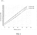
- FIG. 3 is a graphical representation of several example duty cycle curves for fans of two different fan types
- FIG. 4 is a graphical representation of several example duty cycle curves for fans of two additional fan types
- FIG. 5 is a flow diagram illustrating selected elements of an embodiment of a method for a management controller to perform fan typing in an information handling system
- FIG. 6 is a flow diagram illustrating selected elements of an embodiment of a method for anomaly detection for a fan based on changes in a tachometer signal received from the fan;
- FIG. 7 is a flow diagram illustrating selected elements of an embodiment of a method for detecting and mitigating an anomaly associated with a fan in an information handling system.
- FIG. 8 is a graphical representation of multiple histograms in which tachometer signal readings are plotted against different duty cycles, according to some embodiments.
- a hyphenated form of a reference numeral refers to a specific instance of an element and the un-hyphenated form of the reference numeral refers to the collective or generic element.
- widget “72-1” refers to an instance of a widget class, which may be referred to collectively as widgets “72” and any one of which may be referred to generically as a widget “72”.
- an information handling system may include an instrumentality or aggregate of instrumentalities operable to compute, classify, process, transmit, receive, retrieve, originate, switch, store, display, manifest, detect, record, reproduce, handle, or utilize various forms of information, intelligence, or data for business, scientific, control, entertainment, or other purposes.
- an information handling system may be a personal computer, a PDA, a consumer electronic device, a network storage device, or another suitable device and may vary in size, shape, performance, functionality, and price.
- an information handling system may be one of multiple computing devices in a large server system.
- An information handling system may include memory, one or more processing resources such as a central processing unit (CPU) or hardware or software control logic.
- CPU central processing unit
- Additional components of the information handling system may include one or more storage devices, one or more communications ports for communicating with external devices as well as various input and output (I/O) devices, such as a keyboard, a mouse, and a video display.
- the information handling system may also include one or more buses operable to transmit communication between the various hardware components.
- Computer-readable media may include an instrumentality or aggregation of instrumentalities that may retain data and/or instructions for a period of time.
- Computer-readable media may include, without limitation, storage media such as a direct access storage device (e.g., a hard disk drive or floppy disk), a sequential access storage device (e.g., a tape disk drive), compact disk, CD-ROM, DVD, random access memory (RAM), read-only memory (ROM), electrically erasable programmable read-only memory (EEPROM), or flash memory (SSD); as well as communications media such as wires, optical fibers, microwaves, radio waves, and other electromagnetic or optical carriers; or any combination of the foregoing.
- storage media such as a direct access storage device (e.g., a hard disk drive or floppy disk), a sequential access storage device (e.g., a tape disk drive), compact disk, CD-ROM, DVD, random access memory (RAM), read-only memory (ROM), electrically erasable programmable read-only memory (
- the inventors of the present disclosure have developed systems and methods disclosed herein for fan typing and anomaly detection for fans included in, or coupled to, information handling systems.
- the disclosed techniques are not dependent on dedicated fan typing circuitry or wiring and can distinguish between many different types of fans with different electrical specifications.
- the disclosed techniques may also be used for anomaly detection, such as when a fan is missing, has failed, or is experiencing a temporary, permanent, or frequency-specific performance degradation.
- FIGS. 1-8 In particular embodiments are best understood by reference to FIGS. 1-8 , in which like numbers are used to indicate like and corresponding parts.
- FIG. 1 illustrates a block diagram depicting selected elements of an embodiment of information handling system 100 .
- information handling system 100 may represent a personal computing device, such as a personal computer system, a desktop computer, a laptop computer, a notebook computer, etc., operated by a user.
- information handling system 100 may be operated by the user using a keyboard and a mouse (not shown).
- components of information handling system 100 may include, but are not limited to, a processor subsystem 120 , which may comprise one or more processors, and system bus 125 that communicatively couples various system components to processor subsystem 120 including, for example, a memory subsystem 130 , an I/O subsystem 140 , local storage resource 150 , and a network interface 160 .
- System bus 125 may represent a variety of suitable types of bus structures, e.g., a memory bus, a peripheral bus, or a local bus using various bus architectures in selected embodiments.
- such architectures may include, but are not limited to, Micro Channel Architecture (MCA) bus, Industry Standard Architecture (ISA) bus, Enhanced ISA (EISA) bus, Peripheral Component Interconnect (PCI) bus, PCI-Express bus, HYPERTRANSPORTTM (HT) bus, and VIDEO ELECTRONICS STANDARDS ASSOCIATIONTM (VESA) local bus.
- MCA Micro Channel Architecture
- ISA Industry Standard Architecture
- EISA Enhanced ISA
- PCI Peripheral Component Interconnect
- PCI-Express PCI-Express
- HT HYPERTRANSPORTTM
- VESA VIDEO ELECTRONICS STANDARDS ASSOCIATIONTM
- network interface 160 may be a suitable system, apparatus, or device operable to serve as an interface between information handling system 100 and a network. More specifically, network interface 160 may enable information handling system 100 to communicate over a network (not shown) using a suitable transmission protocol or standard.
- the network may include, or be part of, a storage area network (SAN), a personal area network (PAN), a local area network (LAN), a metropolitan area network (MAN), a wide area network (WAN), a wireless local area network (WLAN), a virtual private network (VPN), an intranet, the Internet or another appropriate architecture or system that facilitates the communication of signals, data and messages (generally referred to as data).
- SAN storage area network
- PAN personal area network
- LAN local area network
- MAN metropolitan area network
- WAN wide area network
- WLAN wireless local area network
- VPN virtual private network
- intranet the Internet or another appropriate architecture or system that facilitates the communication of signals, data and messages (generally referred to as data).
- network interface 160 may be communicatively coupled via a network to a network storage resource (not shown).
- the network coupled to network interface 160 may transmit data using a desired storage or communication protocol, including, but not limited to, Fibre Channel, Frame Relay, Asynchronous Transfer Mode (ATM), Internet protocol (IP), other packet-based protocol, small computer system interface (SCSI), Internet SCSI (iSCSI), Serial Attached SCSI (SAS) or another transport that operates with the SCSI protocol, advanced technology attachment (ATA), serial ATA (SATA), advanced technology attachment packet interface (ATAPI), serial storage architecture (SSA), integrated drive electronics (IDE), or any combination thereof.
- the network coupled to network interface 160 or various components associated therewith may be implemented using hardware, software, or any combination thereof.
- processor subsystem 120 may comprise a system, device, or apparatus operable to interpret and/or execute program instructions and process data, and may include a microprocessor, microcontroller, digital signal processor (DSP), application specific integrated circuit (ASIC), or another digital or analog circuitry configured to interpret and execute program instructions and process data.
- processor subsystem 120 may interpret and execute program instructions and process data stored locally (e.g., in memory subsystem 130 or local storage resource 150 ).
- processor subsystem 120 may interpret and execute program instructions and process data stored remotely (e.g., in network storage resources accessed via network interface 160 ).
- a memory subsystem within processor subsystem 120 may include multiple data caches, such as one or more level 1 (L1) caches and/or level 2 (L2) caches (not shown).
- L1 cache may be local to a particular processor or processor core within processor subsystem 120
- level 2 cache may be shared between multiple processors or processor cores within a processor subsystem 120 .
- a cache controller within a memory subsystem of processor subsystem 120 may include circuitry to manage the contents of one or more L1 caches and/or L2 caches.
- memory subsystem 130 may comprise a system, device, or apparatus operable to retain and retrieve program instructions and data for a period of time (e.g., computer-readable media).
- Memory subsystem 130 may comprise random access memory (RAM), electrically erasable programmable read-only memory (EEPROM), a PCMCIA card, flash memory, magnetic storage, opto-magnetic storage, or a suitable selection or array of volatile or non-volatile memory that retains data after power is removed.
- RAM random access memory
- EEPROM electrically erasable programmable read-only memory
- PCMCIA card electrically erasable programmable read-only memory
- flash memory magnetic storage
- opto-magnetic storage or a suitable selection or array of volatile or non-volatile memory that retains data after power is removed.
- memory subsystem 130 may include a level 3 (L3) cache or a last-level cache (not shown), which may be shared between processors or processor cores in multiple processor subsystems 120 .
- L3 cache level
- Local storage resource 150 may comprise computer-readable media (e.g., hard disk drive, floppy disk drive, CD-ROM, and/or other type of rotating storage media, flash memory, EEPROM, or another type of solid state storage media) and may be generally operable to store instructions and data, and to permit access to stored instructions and data on demand.
- local storage resource 150 may include a collection or array of storage devices and a storage controller.
- BIOS NVM non-volatile BIOS memory
- BIOS NVM memory 190 may be implemented using non-volatile random access memory.
- BIOS NVM 190 may include BIOS firmware 192 , representing pre-boot instructions executable by processor subsystem 120 , for example, for preparing information handling system 100 to boot by activating various hardware components in preparation of launching an operating system for execution.
- BIOS firmware 192 which may implement the Basic Input/Output System (BIOS) firmware interface, may further include instructions for displaying a user interface (which may also referred to as a BIOS setup program) by which a user may access, modify, and store BIOS user settings. Also shown stored in BIOS NVM 190 is BIOS storage 194 , which may represent data, such as program code, settings, data values, etc. that BIOS firmware 192 may store. In some embodiments, BIOS firmware 192 may implement a power-on-self-test when information handling system 100 is powered up or restarted following a shutdown. In certain embodiments, BIOS firmware 192 may have access to network interface 160 for various types of communication, such as with a network administrator.
- BIOS firmware 192 may have access to network interface 160 for various types of communication, such as with a network administrator.
- BIOS storage 194 may physically reside on a remote storage resource, such as in a network storage resource (not shown).
- an interface in compliance with the Unified Extensible Firmware Interface (UEFI) specification may replace the Basic Input/Output System (BIOS) firmware interface in the example embodiment illustrated in FIG. 1 .
- the UEFI specification defines a software interface between an operating system and platform firmware.
- I/O subsystem 140 may comprise a system, device, or apparatus generally operable to receive and transmit data to or from or within information handling system 100 .
- I/O subsystem 140 may represent, for example, a variety of communication interfaces, graphics interfaces, video interfaces, user input interfaces, and peripheral interfaces.
- I/O subsystem 140 may comprise a touch panel 142 and a display adapter 144 .
- the touch panel 142 may include circuitry for enabling touch functionality in conjunction with a display device that is driven by the display adapter 144 .
- information handling system 100 also includes a baseboard management controller (BMC) 180 .
- BMC baseboard management controller
- Baseboard management controller 180 includes a BMC processor 182 and BMC firmware 184 that when executed by BMC processor 182 performs the operations of the baseboard management controllers described herein.
- baseboard management controller 180 may monitor the physical state of information handling system 100 as well as devices included within or coupled to information handling system 100 .
- baseboard management controller 180 may be configured to perform remote management operations.
- baseboard management controller 180 may be configured to provide automatic alerts, to initiate power-on or power cycle events, boot or reboot events, or other power control functions on behalf of information handling system 100 .
- baseboard management controller 180 may be configured to perform operations described herein for fan typing and anomaly detection.
- information handing system 100 includes one or more power/fan control modules 170 and one or more power supply units 172 , each of which may include one or more fans 174 .
- power/fan control modules 170 may control the allocation of power generated by one or more of the power supply units 172 to other resources in system 100 .
- one or more of the power/fan control modules 170 may include a management controller (MC).
- the management controller may include circuitry and/or logic to perform operations described herein for fan typing and anomaly detection.
- one or more fans 174 may reside outside of the power supply units 172 , in which case the functionality of power/fan control modules 170 may be divided into separate power control modules and fan control modules (not shown).
- baseboard management controller 180 may be implemented within one or more of the power/fan control modules 170 rather than as a separate component of information handling system 100 .
- baseboard management controller 180 may exchange information and/or control signals with other components of information handling system 100 , such as power/fan control modules 170 , power supply units 172 , and/or fans 174 over a management control bus 115 .
- baseboard management controller 180 may provide controls to and receive information from various power supply units 172 and/or fans 174 through one or more power/fan control modules 170 .
- baseboard management controller 180 may, either directly or through one of the power/fan control modules 170 , provide a PWM control signal 171 as an input to a fan 174 and may receive a tachometer signal 173 that is output from the fan 174 .
- Baseboard management controller 180 may, either directly or through one of the power/fan control modules 170 , exchange information and/or control signals with other elements of power supply units 172 , such as to provide a notification of a result of a fan typing or fan anomaly detection exercise or to control the distribution of power in the information handling system or perform other functions, via one or more analog or digital signals 176 .
- fan typing is typically provided using dedicated motherboard circuitry, fan assembly circuitry, and wire harness wiring.
- the fan assembly circuitry typically includes extra pins on the motherboard and on the fan connector, as well as a wire harness connection of a “type” pin between +12V, GND or float.
- the motherboard circuitry typically includes logic that is able to multiplex in voltage signals from particular fan slots, scale down the voltages, and perform analog to digital conversions to determine the fan type.
- This dedicated circuitry and wiring can typically only grossly determine the fan type. For example, the circuitry might only be able to determine whether or not a fan is present in a particular fan slot or whether an installed fan is a high performance fan or a standard fan with no additional specificity.
- the systems and methods described herein may include optimizations to standard fan to motherboard interfaces such as replacing hardware based fan type detection (using dedicated circuits, firmware, and connectors that increase costs related to board space, fan assembly costs and circuitry complexity) with software based fan typing. This approach may not only decrease system costs but may also increase the quality (e.g., the accuracy) of the fan typing solution.
- the disclosed systems may include preloaded electrical specifications, e.g., data stored in a fan controller or in baseboard management controller tables representing curves in which tachometer signals output by fans of a particular fan type are plotted versus different PWM control signal duty cycles. Tachometer signal readings obtained from a given fan during a system boot phase or during runtime may be compared to the stored curve data to determine the fan type.
- the fans installed in information handling systems work as hard as they can to produce an expected tachometer signal output (in terms of revolutions per minute, or RPM) based on the input PWM duty cycle.
- Various fan failure modes such as broken blades or the presence of debris (e.g., dust or dirt) can affect the ability of a fan to perform with uniform air flow as expected by thermal control algorithms, especially in cases in which in-line dual rotors are not performing as expected.
- the ability of the fan to maintain the expected tachometer signal output corresponding to the duty cycle of its PDM control signal input is negatively impacted.
- existing fan typing techniques it can be difficult to distinguish between a fan of one fan type that has suffered this type of degradation and a fan of a different type with different electrical specifications, leading to incorrect fan typing.
- a baseboard management controller may be operable to capture and plot histograms to detect jitter on the tachometer signal output by a fan and to infer fan wobble based on detecting the tachometer signal jitter.
- management controller firmware may be operable to detect fan wobble for the purposes of better fan typing confidence, for predicating failure events, and/or for inferring vibrational harmonics beyond the pure RPM level, which may then be used to extrapolate the effect of a rotor on other system elements (e.g., a spinning rotor hard disk drive).
- Method 200 may be performed using information handling system 100 (see FIG. 1 ). For example, certain operations may be performed by a baseboard management controller, such as BMC 180 illustrated in FIG. 1 . It is noted that certain operations described in method 200 may be optional or may be rearranged in different embodiments.
- Method 200 may begin, at 202 , by supplying a PWM control signal with a given duty cycle to an input of a fan. The given duty cycle may be greater than or equal to a predetermined threshold duty cycle above which confidence that the potential fan types for the fan can be distinguished from each other is high.
- method 200 may include receiving a tachometer signal output of the fan while the PWM control signal has the given PWM duty cycle.
- the tachometer signal output may be received as data representing a frequency value for the tachometer that is proportional to the fan speed in terms of revaluations per minute (RPM).
- the method may include comparing frequency indicated by the tachometer signal output of the fan to an expected frequency for fans of a given fan type when controlled with the given PWM duty cycle. In some embodiments, this may include looking up the expected value of the frequency for fans of the given fan type when controlled with the given PWM duty cycle in a table maintained by the BMC that stores data representing RPM vs. PWM curves for fans of one or more fan types.
- the given fan type may be an expected fan type for the given fan, according to system configuration information associated with the information handling system.
- the information handling system may include (e.g., in BIOS NVM 190 illustrated in FIG. 1 or in another non-volatile memory location accessible by the BMC) an identifier associated with the particular hardware configuration of the information handling system.
- the BMC may obtain the configuration identifier from the memory and may determine the expected fan type based on the obtained configuration identifier.
- method 200 may include determining, based on the comparison, whether or not the fan is a fan of the given fan type. For example, if the frequency indicated by the tachometer signal output of the fan is equal to, or not statistically different from, an expected frequency for fans of a given fan type when controlled with the given PWM duty cycle, the given fan may be determined to be a fan of the given fan type. However, if the frequency indicated by the tachometer signal output of the fan is statistically different from the expected frequency for fans of a given fan type when controlled with the given PWM duty cycle, this may indicate that the fan is not a fan of the given type or that the fan cannot be typed due to a failure or significant performance degradation.
- the method may include providing an indication of whether or not the fan is a fan of the given fan type to a fan controller.
- an indication that the fan is of the given type may be provided to power/fan control module 170 (e.g., via management control bus 115 ).
- providing the indication that the fan is of the given type may including writing data indicating the result of the fan typing operation to a system log or control table stored in a memory accessible by the power/fan control module 170 or stored in BMC 180 , for example.
- FIG. 3 is a graphical representation 300 of several example duty cycle curves for fans of two different fan types referred to as fan type A and fan type B. More specifically, graph 300 includes five curves, each plotting tachometer signal values (in terms of RPM) versus PWM duty cycle values (in terms of percentages) for a particular 2U fan supplied by a particular vendor.
- fan type A is one of several high performance 2U fan types
- fan type B is one of several standard 2U fan types.
- graph 300 includes respective curves for two fans of fan type A supplied by two different vendors (shown as curves 402 ) and for three fans of fan type B supplied by three different vendors (shown as curves 404 ).
- FIG. 4 is a graphical representation 400 of several example duty cycle curves for fans of two additional fan types referred to as fan type C and fan type D. More specifically, graph 400 includes four curves, each plotting tachometer signal values (in terms of RPM) versus PWM duty cycle percentages for one of the two rotors in a particular 1U fan supplied by a particular vendor.
- fan type C is one of several high performance 1U fan types
- fan type D is one of several standard 1U fan types.
- graph 400 includes respective curves for two fans of a fan type C supplied by two different vendors (shown as curves 406 ) and for two fans of a fan type D supplied by two different vendors (shown as curves 408 ).
- the tachometer signals from the type C fans and the type D fans are similar at very low PWM duty cycle points and deviate at higher PWM duty cycle points.
- a PWM duty cycle of 40% may be sufficient to determine, with high confidence, whether a type C fan or a type D fan is installed.
- FIG. 4 illustrates that there is a roughly 1000 RPM difference (e.g., 8000 vs. 9000) between the curves for type C fans and type D fans when the duty cycle is 40%.
- the techniques described herein may be used to distinguish between more than two types of fans. In some systems, configurations including a mix of fan types, including both standard and high performance fan types, are not supported. However, in some embodiments, the techniques described herein for fan typing may be used to perform fan typing in systems that include fans of multiple different fan types. For example, these techniques may be used to determine a fan type from among multiple low cost fans, multiple mid-range or standard fans, and/or multiple high performance fans from one or multiple vendors, in different embodiments.
- a predetermined threshold duty cycle above which confidence that the potential fan types for the fan can be distinguished from each other is high may be calculated based on historical data, such as that shown in FIGS. 3 and 4 .
- the threshold duty cycle may be programmable, and therefore adaptable to changes in fan technology, system configurations, system workloads, performance goals, environmental factors, or other parameters that affect the expected relationships between PWM control signal duty cycles and tachometer signals.
- optional slots in which there might or might not be a fan installed at any particular time, are not supported.
- the techniques described herein for fan typing may be able to detect whether there is a fan missing in an optional fan slot.
- the systems described herein may initiate a characterization training cycle during which to discern the fan type based on an applicable PWM control signal stimulus to tachometer response curve.
- a training cycle may be initiated automatically upon a BMC boot or a thermal control daemon start.
- a training cycle may be initiated automatically upon detection of a fan hot plug event via a transition from receiving no tachometer pulses to receiving any tachometer pulses while the host system is powered on (e.g., via an interrupt triggered by the first received tachometer edge).
- the BMC may perform fan typing, as described above, for each fan in the information handling system in sequence.
- This may include the BMC firmware causing the PWM control signal duty cycle for each fan slot, in sequence, to ramp up to the predetermined threshold duty cycle, if it is not already operating at that duty cycle point, observing the tachometer response, including collecting data representing the response, and then returning to the previous PWM duty cycle.
- Performing the fan typing based on tachometer reading captured at the predetermined threshold duty cycle point, either at the time of data collection or later, may allow for high confidence in the result, as the curves diverge, while the fan speed is not high enough to create user concern or be excessively noisy.
- the results may be compared to the expected system configuration. For example, if system configuration information indicates that the system should include four fans in particular slots and that high performance fans are required, a comparison between the determined fan types and this expected configuration may be made to see if the required high performance fans are present in the expected fan slots. Note that some users may purchase high performance fans even if the system configuration does not require it. In this case, the techniques described herein may be used to accurately account for inventory usage. In some embodiments, a failed fan (for which the tachometer signal output indicates that the fan speed is below a minimum speed or is below the expectation for a standard fan) may be flagged as failed and may not be positively typed.
- Method 500 may be performed using information handling system 100 (see FIG. 1 ). For example, certain operations may be performed by a baseboard management controller, such as BMC 180 illustrated in FIG. 1 . It is noted that certain operations described in method 500 may be optional or may be rearranged in different embodiments.
- Method 500 may begin at 502 when, in response to system power up and BMC boot in an information handling system, the information handling system begins performing a power-on-self-test. In some embodiments, the power-on-self-test may be performed by the execution of a portion of BIOS firmware (such as BIOS firmware 192 illustrated in FIG. 1 ).
- BIOS firmware such as BIOS firmware 192 illustrated in FIG. 1
- method 500 may include the BMC setting the PWM duty cycle of all fans in the information handling system to a given static duty cycle for the power-on-self-test. Since fan noise increases with fan rotation speed, the given static duty cycle may represent a predetermined default duty cycle for power-on-self-test that has been selected to produce less noise than when the fan is operating in normally and/or for low power operation of the fan. In one example, the given static duty cycle for the power-on-self-test may be less than or equal to 20%.
- the method may include the BMC determining the maximum number of fans in the system and the system configuration requirements for the fans in this system.
- this configuration information may be obtained from a local memory, such as BIOS NVM 190 or another local memory, and may include an indication of the total number of fan slots in the system, an indication of the number of fan slots that are, or that are expected to be, populated in the current configuration of the information handling system, and/or an indication of the performance requirements for each of the fans that are, or are expected to be, present in the information handling system.
- one or more fans may be expected to be high performance fans.
- one or more fans may be expected to be low cost fans.
- all of the fans may have the same performance requirements.
- different fans in the information handling system may have different performance requirement, e.g., depending on their location and/or function within the information handling system.
- method 500 may include, for a given fan in the system, the BMC ramping the PWM duty cycle up from the given static duty cycle for the power-on-self-test to a predetermined confidence threshold value, if necessary, and checking the tachometer signal from the given fan. For example, if the given fan is already operating at or above the predetermined confidence threshold value (e.g., if the static duty cycle for the power-on-self-test for a particular fan is greater than or equal to the predetermined confidence threshold value), there may be no need to ramp up the PWM duty cycle for perform fan typing.
- the predetermined confidence threshold value e.g., if the static duty cycle for the power-on-self-test for a particular fan is greater than or equal to the predetermined confidence threshold value
- the predetermined confidence threshold duty cycle may be a duty cycle that has been statistically shown to represent a duty cycle above which confidence that the potential fan types for the fans in the information handling system can be distinguished from each other is high.
- the predetermined threshold duty cycle may be 40%. In other embodiments, the predetermined threshold duty cycle may be higher or lower than 40%.
- method 500 may continue to 514 . Otherwise, the tachometer signal may indicate that the fan expected to be present in a given fan slot may be missing entirely or may be damaged or degraded to a point at which cannot be typed, as in 512 .
- method 500 proceeds to 516 . Otherwise, the method may continue to 518 .
- output an indication of fan type and the attempt to type the given fan is concluded.
- an indication of the fan type may be provided to power/fan control module 170 (e.g., via management control bus 115 ).
- data indicating the result of the fan typing operation may be written to a system log or control table stored in a memory accessible by the power/fan control module 170 or stored in BMC 180 , for example.
- method 500 may return to 514 , after which the operation shown at 514 may be repeated one or more times to determine if the given fan is a fan of another one of multiple fan types that are possible for fans in the particular slot in the information handling system. If, or once, there are no additional fan types under consideration, the given fan cannot be typed and the attempt to type the given fan is concluded, as in 520 . In some embodiments, once it is determined that the given fan cannot be typed, an indication of the failure of the fan typing attempt may be provided to power/fan control module 170 (e.g., via management control bus 115 ) for subsequent analysis.
- data indicating the failure of the fan typing attempt may be written to a system log or control table stored in a memory accessible by the power/fan control module 170 or stored in BMC 180 , for example.
- method 500 may continue at 522 . If, at 522 , there are more fans in the system to be typed, the method may return to 508 , after which the operations shown in 508 through 520 may be repeated, as appropriate for each additional fan in the system. If, or once, there are no additional fans to be typed, the fan typing operation may be complete, as in 524 .
- a higher than expected tachometer reading may indicate the presence of a broken blade or a blade with debris on it, which may cause the fan to wobble and result in non-uniform tachometer ticks per revolution.
- asymmetric wobble may be detectable by a software function in the BMC firmware that measures tachometer tick cycle to cycle jitter and plots the measurement in a histogram. The crossing of a statistical threshold of tachometer cycle to cycle jitter may trigger a predictive failure sensor or may be used to inform a further refinement of physical fan type installed.
- this statistical jitter method for detecting wobble and asymmetric spinning may be used to infer localized, slot-specific fan vibrations outside of the expected tachometer signal harmonics.
- This information may be useful in a thermal control algorithm for the purpose of intelligently “steering” fan speeds away from sensitive vibration points that may adversely affect entities within the vicinity of that fan motor, such as rotating hard drives. This may help maximize spinning rotor drive throughput by reducing the access error rate.
- a hard drive might be sensitive to certain frequency variations.
- firmware may be operable to avoid those frequencies.
- the BMC firmware may avoid supplying a PWM control signal to the fan having a duty cycle associated with tachometer signal values corresponding to the problem frequencies.
- a notification e.g., a flag or warning
- a notification may be provided indicating that further investigation may be needed or that a fan may need to be replaced, among other potential corrective actions.
- method 600 may be performed using information handling system 100 (see FIG. 1 ).
- certain operations may be performed by a baseboard management controller, such as by executing a portion of BMC firmware 184 on BMC processor 182 of BMC 180 illustrated in FIG. 1 .
- certain operations may be performed by executing, on processor subsystem 120 , program instructions stored locally (e.g., in memory subsystem 130 , or local storage resource 150 ) or remotely (e.g., in a network storage resource accessible through network interface 160 ).
- Method 600 may begin at 602 when, during a training period, the information handling system begins logging a tachometer signal (in terms of RPM) while running a given fan with a fixed PWM duty cycle input.
- the fixed PWM duty cycle may represent a predetermined confidence threshold value, as described above.
- method 600 may include calculating and saving data representing an average RPM reading collected during the training period.
- the data representing the average RPM reading collected during the training period may be stored locally (e.g., in memory subsystem 130 , or local storage resource 150 ) or remotely (e.g., in a network storage resource accessible through network interface 160 ).
- the method may include generating a histogram representing the number of occurrences of RPM values in each of multiple bins of RPM values, identifying the top bins represented in the histogram, and saving the data representing the top bins and the number of occurrences of RPM values in each of the top bins or in each of the multiple bins.
- the data representing the top bins and the number of occurrences of RPM values in each of the top bins or in each of the multiple bins collected during the training period may be stored locally (e.g., in memory subsystem 130 , or local storage resource 150 ) or remotely (e.g., in a network storage resource accessible through network interface 160 ).
- a histogram tool of a spreadsheet application may be operable to count the number of data points in each data bin.
- a data point may be included in a particular data bin if its value is greater than the lower bound for the data bin and is less than or equal to the upper bound for the data bin. If the data range for the bins is not specified, the spreadsheet tool may create a set of evenly distributed bins between the minimum and maximum values of the input data.
- a re-evaluation may be performed periodically (e.g., on a predetermined schedule) or may be initiated in response to a configuration change in the information handling system, such as the addition of a fan or another component in the information handling system (using a hot plug installation or an installation while at least some parts of the system are shut down), the replacement of a fan or another component in the information handling system (using a hot swap installation or a replacement while at least some parts of the system are shut down), a software patch or upgrade, or another type of hardware or software configuration change.
- the results of the analysis may be saved as new reference data with which subsequently collected data is to be compared rather than, or in addition to, being compared to the reference data collected during the training phase.
- method 600 may include, for another period of time, logging the tachometer signal (in terms of RPM) while running the fan with the fixed PWM duty cycle, and then calculating and saving data representing an average RPM reading collected during the other period of time.
- the data representing the average RPM reading collected during the other period may be stored locally (e.g., in memory subsystem 130 , or local storage resource 150 ) or remotely (e.g., in a network storage resource accessible through network interface 160 ).
- the method may include scaling a new set of bins to align with the reference RPM data, generating new histogram, and identifying the top bins (and the corresponding numbers of occurrences in each of the top bins or all bins) in the new histogram.
- method 600 may continue at 618 .
- the method may include identifying a potential failure or performance degradation of the given fan based on the presence of one or more new top bins and/or lower numbers of occurrences for particular bins compared to the reference data. Regardless of whether or not an anomaly was detected, method 600 may return to 608 . If and when conditions indicate that it is time for a further re-evaluation, the operations shown in 610 through 618 may be repeated, as appropriate, for each successive re-evaluation.
- the operations of method 600 shown in FIG. 6 may be performed independently for each fan in the information handling system to detect any anomalies associated with particular ones of the fans.
- the operations shown as 602 - 606 and/or 610 - 618 may be performed (independently) for multiple fans in parallel.
- these operations may be performed for one fan at a time until they have been completed on all fans.
- the behavior of the fan and/or the system in which it resides may be characterized more thoroughly by introducing perturbations in the PWM control signal and observing the resulting tachometer signal changes.
- the behavior of a high performance fan that normally operates at a relatively low speed e.g., with a tachometer signal and fan speed corresponding to a PWM control signal duty cycle of 10%
- the behavior of a fan may be characterized by providing a PWM control signal for which the duty cycle is ramped up or down incrementally while the resulting tachometer signal output is observed.
- an indication of the anomaly may be provided a fan controller, such as a power/fan controller 170 illustrated in FIG. 1 , a management controller residing in the power/fan controller 170 , a baseboard management controller such as BMC 180 , or another component of the information handling system in which the fan is installed that includes circuitry or logic affecting the operation of the fan.
- the fan controller may react in any number of ways, in different embodiments, to further characterize or attempt to mitigate the detected anomaly. The actions taken may include but are not limited to:
- method 700 may be performed using information handling system 100 (see FIG. 1 ).
- certain operations may be performed by a baseboard management controller, such as by executing a portion of BMC firmware 184 on BMC processor 182 of BMC 180 illustrated in FIG. 1 .
- certain operations may be performed by executing, on processor subsystem 120 , program instructions stored locally (e.g., in memory subsystem 130 , or local storage resource 150 ) or remotely (e.g., in a network storage resource accessible through network interface 160 ).
- Method 700 may begin at 702 by identifying a potential failure or performance degradation of a given fan based on an anomaly observed in an analysis of the top RPM bins and/or numbers of occurrences in each bin of a histogram of the occurrences of RPM values in particular RPM value ranges, e.g., as illustrated in FIG. 6 and described above. For example, the presence of one or more new top bins and/or lower numbers of occurrences for particular bins compared to the reference data may indicate a potential fan problem.
- a potential fan problem may be indicated if the amount of the deviation from the reference data meets a particular threshold value. For example, a threshold value at which a lower number of occurrences for a particular bin is considered significant may be set at 80% of the reference data. In this example, if the number of occurrences in a particular bin is at least 20% lower than indicated in the reference data, a potential failure or performance degradation of the given fan may be identified. In another example, a threshold value at which the presence of new top bins is considered significant may be set at 20% of the reference data. In this example, if the number of top bins present in the most recently generated histogram that are not present in the reference data represents at least 20% of the number of top bins identified in the reference data, a potential failure or performance degradation of the given fan may be identified.
- method 700 may proceed to 706 . Otherwise, the method may continue at 708 . For example, if the tachometer signal for the given fan does not meet a minimum specification for all fan types, this may indicate that the fan has suffered a serious or fatal failure. If no tachometer signal is received from the fan slot in which the given fan is expected to be present, this may indicate that there is no fan in the slot. At 706 , the method may include generating a notification of a potential problem with the given fan.
- an indication of the potential problem may be provided to power/fan control module 170 (e.g., via management control bus 115 ).
- data indicating the potential problem may be written to a system log or control table stored in a memory accessible by the power/fan control module 170 or stored in BMC 180 , for example.
- the method may proceed to 710 . Otherwise, the anomaly may indicate a more general performance degradation and the method may continue at 712 .
- the method may include programming a fan controller to skip over the problem frequencies when ramping the PWM duty cycle up or down.
- method 700 may include increasing the fan speed by an incremental amount as a countermeasure to the detected fan performance degradation issue, and then repeating the data collection and analysis described above in reference to the re-evaluation of the given fan.
- method 700 may proceed to 724 , where no further action is taken. If, however, the analysis indicates that the detected issue has not been corrected, the method may continue at 716 .
- method 700 may continue at 718 . Otherwise, the method may return to 712 , after which the fan speed may be further reduced one or more times in an attempt to correct the detected issue, as in operations 714 and 716 .
- the method may include invoking system power throttling to reduce the thermal effects of the detected fan performance degradation issue, if any, and then repeating the data collection and analysis to determine whether the detected issue (whether includes a performance issue, a thermal issue, or both) has been corrected.
- method 700 may proceed to 724 , at which point no further action is necessary. However, if the analysis indicates that the detected issue has still not been resolved, the method may proceed to 722 , after which a notification of the potential problem may be generated.
- an indication of the potential problem may be provided to power/fan control module 170 (e.g., via management control bus 115 ).
- data indicating the potential problem may be written to a system log or control table stored in a memory accessible by the power/fan control module 170 or stored in BMC 180 , for example.
- While the example method for detecting and mitigating an anomaly associated with a fan in an information handling system illustrated in FIG. 7 includes incrementally increasing the fan speed prior until it reaches its maximum speed, in other embodiments, the fan speed may be increased to its maximum speed with first attempting to mitigate the detected anomaly through incremental speed increases. In still other embodiments, power throttling may be invoked before, at the same time as, during, or instead of an attempt to mitigate the detected anomaly through incremental speed increases or setting the fan speed to it maximum speed.
- FIG. 8 is a graphical representation 800 of multiple histograms in which tachometer signal readings (in terms of RPM) collected during various experiments are plotted against different duty cycles (in terms of percentage), as described above, for different conditions.
- the first set of histograms represented in FIG. 8 by the left-most column in each grouping of three columns, was generated from tachometer readings taken during normal operation of a particular fan and are used as baseline measurements.
- the second set of histograms, represented in FIG. 8 by the middle column in each grouping of three columns was generated from tachometer readings taken under a first test condition, in which fan blades were touched with 28 gauge (AWG) wire.
- the third set of histograms represented in FIG. 8 by the right-most column in each grouping of three columns, was generated from tachometer readings taken under a second test condition, in which one fan blade was broken off.
- Each log includes, for a particular one of the three conditions described above, entries including the respective histogram bins and the numbers of occurrences (data points) in each bin.
- the raw data collected from the logic analyzer also included timestamps and the state of the tachometer (1 or 0) (not shown).
- the value shown for a given bin represents the upper boundary of the given bin and the lower boundary of the given bin is the value shown for the previous bin.
- the top bins (e.g., those having the highest number of occurrences) include 650, 683, and 573 occurrences, respectively. These bins are identified in FIG. 8 by the labels 802 , 804 , and 806 , respectively.
- the top three bins for test case 2 include 538, 501, and 48 occurrences, respectively. These bins are identified in FIG. 8 by the labels 812 , 810 , and 816 , respectively.
- Bins with significantly altered numbers of occurrences compared to the baseline case include those bins labeled collectively as 808 (one of which has a lower number of occurrences than in the baseline case and one of which has a higher number of occurrences than in the baseline case), and the bins labeled as 810 and 814 (each of which has a lower number of occurrences than in the baseline case).
- the broken fan blade affected the behavior of the fan enough for the changes to be reflected in the tachometer signal output. More specifically, with one blade missing (and a corresponding lighter load on the fan), bins shifted down slightly, indicating that the fan sped up slightly.
- the new top bins are indicative of vibrations due to the fan being out of balance and uneven pressures as the blades pass the stationary plastic parts.
- an information handling system may, in some embodiments, implement systems and methods for fan typing and anomaly detection based on the expected and observed relationships between tachometer signal outputs and PWM control signal inputs, and deviations therefrom.
- These techniques do not require dedicated circuitry for fan typing nor a dedicated fan type pin (and associated wiring), as is the case with existing solutions.
- This provides technical benefits by reducing the amount and complexity of the circuitry needed to perform fan typing and anomaly detection and the corresponding financial benefits of reducing the board space and number components (e.g., circuitry and connectors) needed to implement this functionality.
- the software based fan typing and anomaly detection approaches described herein may be performed in an unobtrusive manner (e.g., in terms of power and/or sound) during a system boot phase and during runtime rediscovery following a configuration change in the system, such as through hot-plugging or a software upgrade.
- the systems described herein may include a BMC subsystem that uses tachometer signal interrupts to calculate tachometer signal jitter and a subsequent determination of asymmetric fan wobble corresponding to the tachometer signal jitter.
- the systems and methods described herein may use calculated fan wobble rates to determine the actual vibration signature of a fan, and may inform control mechanism that skip over certain PWM duty cycle points at which potential problems (such as for drive throughput) were identified using calculation of excursions such as wobble.
Landscapes
- Engineering & Computer Science (AREA)
- Combustion & Propulsion (AREA)
- General Engineering & Computer Science (AREA)
- Mechanical Engineering (AREA)
- Chemical & Material Sciences (AREA)
- Signal Processing (AREA)
- Physics & Mathematics (AREA)
- Mathematical Physics (AREA)
- Human Computer Interaction (AREA)
- Microelectronics & Electronic Packaging (AREA)
- Fuzzy Systems (AREA)
- Power Engineering (AREA)
- Health & Medical Sciences (AREA)
- Biomedical Technology (AREA)
- Thermal Sciences (AREA)
- Cooling Or The Like Of Electrical Apparatus (AREA)
Abstract
Description
-
- logging the detection of the anomaly in a system event log, which may provide a user with a notification of a potential problem with a particular fan
- initiating a fan speed offset, in which the fan speed is increased incrementally as a countermeasure to a potential fan failure
- setting the fan speed to its maximum value, as an alternative to an incremental system fan speed increase
- invoking system power throttling to ensure that system thermal measurements are within defined limits
| TABLE 1 |
| Histogram Data |
| BASELINE | TEST CONDITION 1 | TEST CONDITION 2 |
| occur- | occur- | occur- | |||
| bin | rences | bin | rences | bin | rences |
| 0.002984 | 1 | 0.002984 | 1 | 0.002963 | 1 |
| 0.002993 | 650 | 0.002993 | 650 | 0.002972 | 364 |
| 0.003001 | 124 | 0.003001 | 124 | 0.002982 | 362 |
| 0.00301 | 0 | 0.00301 | 0 | 0.002991 | 48 |
| 0.003019 | 0 | 0.003019 | 0 | 0.003 | 0 |
| 0.003028 | 93 | 0.003028 | 93 | 0.003009 | 104 |
| 0.003037 | 683 | 0.003037 | 683 | 0.003019 | 501 |
| 0.003046 | 0 | 0.003046 | 0 | 0.003028 | 122 |
| 0.003055 | 0 | 0.003055 | 0 | 0.003037 | 48 |
| 0.003064 | 0 | 0.003064 | 0 | 0.003046 | 0 |
| 0.00341 | 0 | 0.00341 | 0 | 0.003406 | 0 |
| 0.003419 | 0 | 0.003419 | 0 | 0.003415 | 136 |
| 0.003428 | 0 | 0.003428 | 0 | 0.003425 | 538 |
| 0.003437 | 202 | 0.003437 | 202 | 0.003434 | 70 |
| 0.003446 | 573 | 0.003446 | 573 | 0.003443 | 93 |
| 0.003454 | 0 | 0.003454 | 0 | 0.003452 | 481 |
| 0.003463 | 12 | 0.003463 | 12 | 0.003462 | 185 |
Claims (14)
Priority Applications (1)
| Application Number | Priority Date | Filing Date | Title |
|---|---|---|---|
| US16/017,222 US10866006B2 (en) | 2018-06-25 | 2018-06-25 | Systems and methods for fan typing and anomaly detection |
Applications Claiming Priority (1)
| Application Number | Priority Date | Filing Date | Title |
|---|---|---|---|
| US16/017,222 US10866006B2 (en) | 2018-06-25 | 2018-06-25 | Systems and methods for fan typing and anomaly detection |
Publications (2)
| Publication Number | Publication Date |
|---|---|
| US20190390864A1 US20190390864A1 (en) | 2019-12-26 |
| US10866006B2 true US10866006B2 (en) | 2020-12-15 |
Family
ID=68981532
Family Applications (1)
| Application Number | Title | Priority Date | Filing Date |
|---|---|---|---|
| US16/017,222 Active US10866006B2 (en) | 2018-06-25 | 2018-06-25 | Systems and methods for fan typing and anomaly detection |
Country Status (1)
| Country | Link |
|---|---|
| US (1) | US10866006B2 (en) |
Cited By (4)
| Publication number | Priority date | Publication date | Assignee | Title |
|---|---|---|---|---|
| US20220099100A1 (en) * | 2019-05-22 | 2022-03-31 | Hewlett-Packard Development Company, L.P. | Identification signals for fans |
| US12173720B2 (en) * | 2020-03-05 | 2024-12-24 | Panasonic Intellectual Property Management Co., Ltd. | Identification method and air blowing system |
| US20250036721A1 (en) * | 2023-07-28 | 2025-01-30 | Dell Products L.P. | Detecting anomalies in device telemetry data using distributional distance determinations |
| US12393239B2 (en) | 2023-06-27 | 2025-08-19 | Dell Products Lp | Method and apparatus for an embedded controller (EC) used to identify different installed cooling fan types and operating performance configurations |
Families Citing this family (20)
| Publication number | Priority date | Publication date | Assignee | Title |
|---|---|---|---|---|
| US11402882B2 (en) * | 2018-09-19 | 2022-08-02 | Hewlett Packard Enterprise Development Lp | Pulse width modulation fan |
| CN109236714B (en) * | 2018-11-06 | 2020-08-07 | 英业达科技有限公司 | Fan control circuit and fan control system |
| US20220099099A1 (en) * | 2019-05-22 | 2022-03-31 | Hewlett-Packard Development Company, L.P. | Identification signals for fans |
| US11687134B2 (en) * | 2020-05-19 | 2023-06-27 | Quanta Computer Inc. | Cooling device identification |
| US11333574B2 (en) * | 2020-05-19 | 2022-05-17 | Dell Products L.P. | Method for monitoring cooling fan performance and system therefor |
| CN113961415A (en) * | 2020-07-20 | 2022-01-21 | 广达电脑股份有限公司 | Cooling device identification system |
| CN112360788B (en) * | 2020-10-15 | 2023-04-21 | 宁畅信息产业(北京)有限公司 | Fan stability testing method and device, computer equipment and storage medium |
| US11661950B2 (en) * | 2020-11-20 | 2023-05-30 | Lg Energy Solution, Ltd. | Diagnostic system for a vehicle |
| CN112799916B (en) * | 2021-02-02 | 2024-03-29 | 中诚华隆计算机技术有限公司 | Monitoring method, device and system for server fan |
| CN113359963A (en) * | 2021-04-29 | 2021-09-07 | 山东英信计算机技术有限公司 | Method, device and equipment for monitoring fan aging and readable medium |
| KR20230029323A (en) * | 2021-08-24 | 2023-03-03 | 삼성전자주식회사 | Storage package, storage device and method for operation the storage device |
| CN114115490B (en) * | 2021-10-31 | 2023-07-25 | 郑州云海信息技术有限公司 | A server fan control method, system, device and medium |
| CN114326990B (en) * | 2021-11-30 | 2023-06-23 | 苏州浪潮智能科技有限公司 | Fan abnormality handling method, device, electronic equipment and storage medium |
| US11836023B2 (en) * | 2022-03-08 | 2023-12-05 | Dell Products L.P. | Automatic detection of cooling system based on a tachometer signal |
| CN116932314A (en) * | 2022-04-08 | 2023-10-24 | 戴尔产品有限公司 | Cooling capability degradation diagnosis in an information handling system |
| CN114837979B (en) * | 2022-05-10 | 2023-09-12 | 联想长风科技(北京)有限公司 | Fan control method and system |
| CN115355190B (en) * | 2022-08-05 | 2026-03-17 | 中国长城科技集团股份有限公司 | Fan specification identification methods, devices, electronic equipment and storage media |
| US12596998B2 (en) * | 2023-01-30 | 2026-04-07 | Dell Products Lp | System and method for a refurbishable fan assembly |
| CN120044937A (en) * | 2025-04-27 | 2025-05-27 | 沐曦集成电路(南京)有限公司 | Verification method, verification device, verification equipment, verification medium and verification program product for fan controller |
| CN120720257B (en) * | 2025-08-25 | 2025-11-21 | 浪潮电子信息产业股份有限公司 | Fan testing method and electronic equipment |
Citations (44)
| Publication number | Priority date | Publication date | Assignee | Title |
|---|---|---|---|---|
| US6262400B1 (en) * | 2000-10-03 | 2001-07-17 | Delphi Technologies, Inc. | Control method for a resistance heater in a vehicle heating system |
| US6428282B1 (en) * | 1999-06-14 | 2002-08-06 | Hewlett-Packard Company | System with fan speed synchronization control |
| US20040009074A1 (en) * | 2002-07-15 | 2004-01-15 | Adc Dsl Systems, Inc. | Fan control system |
| US20040257024A1 (en) * | 2003-06-11 | 2004-12-23 | Marando Eileen M. | Programmable PWM stretching for tachometer measurement |
| US20050077849A1 (en) * | 2003-10-07 | 2005-04-14 | Twinhead International Corp. | Motor speed detecting device for use between motor and system |
| US20050238336A1 (en) * | 2003-09-22 | 2005-10-27 | Bekker Leonid A | Method and apparatus to achieve accurate fan tachometer with programmable look-up table |
| US20060117779A1 (en) * | 2004-12-03 | 2006-06-08 | Frank Liebenow | Method of determining cooling system effectiveness |
| US20060152891A1 (en) * | 2005-01-07 | 2006-07-13 | Elie Jreij | System and method for communication with an information handling system cooling fan |
| CN1811197A (en) * | 2005-01-28 | 2006-08-02 | 鸿富锦精密工业(深圳)有限公司 | Rotation speed detecting device and method for brushless DC PWM fan |
| US20070019383A1 (en) * | 2005-07-09 | 2007-01-25 | Chang Yu-Chen | System and method for automatically detecting a type of a cpu fan |
| CN1913334A (en) * | 2005-08-09 | 2007-02-14 | 中兴通讯股份有限公司 | Speed regulating fan system with fault-tolerant capacity |
| US20070098374A1 (en) * | 2005-10-31 | 2007-05-03 | Nobuto Fujiwara | Information processing apparatus and fan control method |
| US20070108923A1 (en) * | 2005-11-16 | 2007-05-17 | Tyan Computer Corporation | Apparatus and method for driving different fans |
| US20070201612A1 (en) * | 2006-02-24 | 2007-08-30 | Delta Electronics, Inc. | Fan system and detector thereof |
| US20070229291A1 (en) * | 2006-03-31 | 2007-10-04 | Tyan Computer Corporation | Universal apparatus for driving diverse fans |
| US20080007194A1 (en) * | 2006-03-31 | 2008-01-10 | Philippe Mace | Method of servo controlling the speed of an electric motor on start-up, and apparatus implementing the system |
| US20080165482A1 (en) * | 2007-01-09 | 2008-07-10 | Samsung Electronics Co., Ltd. | Display apparatus, fan unit and fan speed control method thereof |
| JP2008208806A (en) * | 2007-02-27 | 2008-09-11 | Nec Corp | Fan failure diagnosis device, method and program |
| CN101334673A (en) * | 2007-06-29 | 2008-12-31 | 鸿富锦精密工业(深圳)有限公司 | Computer fan control circuit and control method |
| CN101443718A (en) * | 2004-12-23 | 2009-05-27 | 美蓓亚株式会社 | Microcontroller methods of improving reliability in DC brushless motors and cooling fans |
| US20090169188A1 (en) * | 2008-01-02 | 2009-07-02 | Winbond Electronics Corporation | Apparatus and method for fan auto-detection |
| DE102008017555A1 (en) * | 2008-04-07 | 2009-10-08 | Winbond Electronics Corp. | Device for detecting fan type and controlling fan e.g. 4-wire pulse width modulation fan, in computer, has tachometer connected with direct current generator and receiving tachometer signal to detect change in speed of fan |
| US20090289590A1 (en) * | 2008-05-23 | 2009-11-26 | Huang Pai-Ching | System and method for compensating characteristics of a fan |
| US20100007795A1 (en) * | 2008-07-09 | 2010-01-14 | Bing Ouyang | System and Method for Clock Offset Detection |
| US20110093109A1 (en) * | 2008-03-25 | 2011-04-21 | Sicpa Holdings Sa | Method and system for controlling production of items |
| US20110156630A1 (en) * | 2009-12-24 | 2011-06-30 | Pegatron Corporation | Device and Method for Detecting Type of Fan |
| US20110199034A1 (en) * | 2010-02-12 | 2011-08-18 | Wu Ming-Chang | Fan control system capable of modulating a rotational speed of a fan and method thereof |
| US20120035769A1 (en) * | 2010-08-06 | 2012-02-09 | Hon Hai Precision Industry Co., Ltd. | System and method for controlling an electronic device fan |
| JP2013041093A (en) * | 2011-08-15 | 2013-02-28 | Canon Inc | Image forming apparatus |
| US20130054047A1 (en) * | 2011-08-31 | 2013-02-28 | Stephen G. Uhlmann | Identifying a fan connected to a computing device |
| US20130079626A1 (en) * | 2011-09-26 | 2013-03-28 | Andriy Shmatukha | Systems and methods for automated dynamic contrast enhancement imaging |
| CN103501690A (en) * | 2011-03-23 | 2014-01-08 | 雷斯梅德有限公司 | Detection of ventilation sufficiency |
| US20140028292A1 (en) * | 2012-07-30 | 2014-01-30 | International Business Machines Corporation | Identification system and electronic system for identifying a fan type of a fan |
| US20140192475A1 (en) * | 2013-01-10 | 2014-07-10 | Eric M. Tunks | System and Method of Controlling an Air Mover |
| US20140310039A1 (en) * | 2013-04-16 | 2014-10-16 | Centurylink Intellectual Property Llc | Automated Cloud Expansion and Ordering System and Method |
| US20150170514A1 (en) * | 2013-12-13 | 2015-06-18 | Here Global B.V. | Systems and Methods for Detecting Road Congestion and Incidents in Real Time |
| CN104763665A (en) * | 2015-03-04 | 2015-07-08 | 杭州华三通信技术有限公司 | Fan fault detection method and device of network device |
| CN105224047A (en) * | 2014-06-09 | 2016-01-06 | 华为技术有限公司 | Fan, fan governor, electronic equipment and fan recognition methods |
| US20160144713A1 (en) * | 2014-11-26 | 2016-05-26 | Tomtom Telematics B.V. | Apparatus and method for determining an advised driving speed |
| US20160239067A1 (en) * | 2015-02-12 | 2016-08-18 | Dell Products L.P. | Fan speed determination for improved power management in information handling systems |
| US20170061638A1 (en) * | 2014-02-19 | 2017-03-02 | Giesecke & Devrient Gmbh | Method for Examining a Value Document, and Means for Carrying out the Method |
| US20170209339A1 (en) * | 2016-01-22 | 2017-07-27 | Hayward Industries, Inc. | Systems and Methods for Providing Network Connectivity and Remote Monitoring, Optimization, and Control of Pool/Spa Equipment |
| US20180316289A1 (en) * | 2017-05-01 | 2018-11-01 | Nidec Corporation | Brushless dc motor, and identification method and identification apparatus of identifying type of brushless dc motor |
| US20180373300A1 (en) * | 2017-06-21 | 2018-12-27 | Cisco Technology, Inc. | Predictive monitoring of computer cooling systems |
-
2018
- 2018-06-25 US US16/017,222 patent/US10866006B2/en active Active
Patent Citations (45)
| Publication number | Priority date | Publication date | Assignee | Title |
|---|---|---|---|---|
| US6428282B1 (en) * | 1999-06-14 | 2002-08-06 | Hewlett-Packard Company | System with fan speed synchronization control |
| US6262400B1 (en) * | 2000-10-03 | 2001-07-17 | Delphi Technologies, Inc. | Control method for a resistance heater in a vehicle heating system |
| US20040009074A1 (en) * | 2002-07-15 | 2004-01-15 | Adc Dsl Systems, Inc. | Fan control system |
| US20040257024A1 (en) * | 2003-06-11 | 2004-12-23 | Marando Eileen M. | Programmable PWM stretching for tachometer measurement |
| US20050238336A1 (en) * | 2003-09-22 | 2005-10-27 | Bekker Leonid A | Method and apparatus to achieve accurate fan tachometer with programmable look-up table |
| US20050077849A1 (en) * | 2003-10-07 | 2005-04-14 | Twinhead International Corp. | Motor speed detecting device for use between motor and system |
| US20060117779A1 (en) * | 2004-12-03 | 2006-06-08 | Frank Liebenow | Method of determining cooling system effectiveness |
| CN101443718A (en) * | 2004-12-23 | 2009-05-27 | 美蓓亚株式会社 | Microcontroller methods of improving reliability in DC brushless motors and cooling fans |
| US20060152891A1 (en) * | 2005-01-07 | 2006-07-13 | Elie Jreij | System and method for communication with an information handling system cooling fan |
| CN1811197A (en) * | 2005-01-28 | 2006-08-02 | 鸿富锦精密工业(深圳)有限公司 | Rotation speed detecting device and method for brushless DC PWM fan |
| US20070019383A1 (en) * | 2005-07-09 | 2007-01-25 | Chang Yu-Chen | System and method for automatically detecting a type of a cpu fan |
| CN1913334A (en) * | 2005-08-09 | 2007-02-14 | 中兴通讯股份有限公司 | Speed regulating fan system with fault-tolerant capacity |
| US20070098374A1 (en) * | 2005-10-31 | 2007-05-03 | Nobuto Fujiwara | Information processing apparatus and fan control method |
| US20070108923A1 (en) * | 2005-11-16 | 2007-05-17 | Tyan Computer Corporation | Apparatus and method for driving different fans |
| US20070201612A1 (en) * | 2006-02-24 | 2007-08-30 | Delta Electronics, Inc. | Fan system and detector thereof |
| US20070229291A1 (en) * | 2006-03-31 | 2007-10-04 | Tyan Computer Corporation | Universal apparatus for driving diverse fans |
| US20080007194A1 (en) * | 2006-03-31 | 2008-01-10 | Philippe Mace | Method of servo controlling the speed of an electric motor on start-up, and apparatus implementing the system |
| US20080165482A1 (en) * | 2007-01-09 | 2008-07-10 | Samsung Electronics Co., Ltd. | Display apparatus, fan unit and fan speed control method thereof |
| JP2008208806A (en) * | 2007-02-27 | 2008-09-11 | Nec Corp | Fan failure diagnosis device, method and program |
| CN101334673A (en) * | 2007-06-29 | 2008-12-31 | 鸿富锦精密工业(深圳)有限公司 | Computer fan control circuit and control method |
| US20090003806A1 (en) * | 2007-06-29 | 2009-01-01 | Hong Fu Jin Precision Industry (Shenzhen) Co., Ltd. | Method and circuit for controlling rotation speed of computer fan |
| US20090169188A1 (en) * | 2008-01-02 | 2009-07-02 | Winbond Electronics Corporation | Apparatus and method for fan auto-detection |
| US20110093109A1 (en) * | 2008-03-25 | 2011-04-21 | Sicpa Holdings Sa | Method and system for controlling production of items |
| DE102008017555A1 (en) * | 2008-04-07 | 2009-10-08 | Winbond Electronics Corp. | Device for detecting fan type and controlling fan e.g. 4-wire pulse width modulation fan, in computer, has tachometer connected with direct current generator and receiving tachometer signal to detect change in speed of fan |
| US20090289590A1 (en) * | 2008-05-23 | 2009-11-26 | Huang Pai-Ching | System and method for compensating characteristics of a fan |
| US20100007795A1 (en) * | 2008-07-09 | 2010-01-14 | Bing Ouyang | System and Method for Clock Offset Detection |
| US20110156630A1 (en) * | 2009-12-24 | 2011-06-30 | Pegatron Corporation | Device and Method for Detecting Type of Fan |
| US20110199034A1 (en) * | 2010-02-12 | 2011-08-18 | Wu Ming-Chang | Fan control system capable of modulating a rotational speed of a fan and method thereof |
| US20120035769A1 (en) * | 2010-08-06 | 2012-02-09 | Hon Hai Precision Industry Co., Ltd. | System and method for controlling an electronic device fan |
| CN103501690A (en) * | 2011-03-23 | 2014-01-08 | 雷斯梅德有限公司 | Detection of ventilation sufficiency |
| JP2013041093A (en) * | 2011-08-15 | 2013-02-28 | Canon Inc | Image forming apparatus |
| US20130054047A1 (en) * | 2011-08-31 | 2013-02-28 | Stephen G. Uhlmann | Identifying a fan connected to a computing device |
| US20130079626A1 (en) * | 2011-09-26 | 2013-03-28 | Andriy Shmatukha | Systems and methods for automated dynamic contrast enhancement imaging |
| US20140028292A1 (en) * | 2012-07-30 | 2014-01-30 | International Business Machines Corporation | Identification system and electronic system for identifying a fan type of a fan |
| US20140192475A1 (en) * | 2013-01-10 | 2014-07-10 | Eric M. Tunks | System and Method of Controlling an Air Mover |
| US20140310039A1 (en) * | 2013-04-16 | 2014-10-16 | Centurylink Intellectual Property Llc | Automated Cloud Expansion and Ordering System and Method |
| US20150170514A1 (en) * | 2013-12-13 | 2015-06-18 | Here Global B.V. | Systems and Methods for Detecting Road Congestion and Incidents in Real Time |
| US20170061638A1 (en) * | 2014-02-19 | 2017-03-02 | Giesecke & Devrient Gmbh | Method for Examining a Value Document, and Means for Carrying out the Method |
| CN105224047A (en) * | 2014-06-09 | 2016-01-06 | 华为技术有限公司 | Fan, fan governor, electronic equipment and fan recognition methods |
| US20160144713A1 (en) * | 2014-11-26 | 2016-05-26 | Tomtom Telematics B.V. | Apparatus and method for determining an advised driving speed |
| US20160239067A1 (en) * | 2015-02-12 | 2016-08-18 | Dell Products L.P. | Fan speed determination for improved power management in information handling systems |
| CN104763665A (en) * | 2015-03-04 | 2015-07-08 | 杭州华三通信技术有限公司 | Fan fault detection method and device of network device |
| US20170209339A1 (en) * | 2016-01-22 | 2017-07-27 | Hayward Industries, Inc. | Systems and Methods for Providing Network Connectivity and Remote Monitoring, Optimization, and Control of Pool/Spa Equipment |
| US20180316289A1 (en) * | 2017-05-01 | 2018-11-01 | Nidec Corporation | Brushless dc motor, and identification method and identification apparatus of identifying type of brushless dc motor |
| US20180373300A1 (en) * | 2017-06-21 | 2018-12-27 | Cisco Technology, Inc. | Predictive monitoring of computer cooling systems |
Non-Patent Citations (2)
| Title |
|---|
| 1-of-8 Fet Multiplexer/Demultiplexer 2.5-V/3.3-V Low-Voltage High-Bandwidth Bus Switch, SN74CB3Q3251, Revised Mar. 2005, Texas Instruments www.ti.com; 21 pages. |
| Low-Voltage, CMOS Analog Multiplexers/Switches, Max4581/Max4582/Max4583, www.maxim-ic.com, 2012; 17 pages. |
Cited By (4)
| Publication number | Priority date | Publication date | Assignee | Title |
|---|---|---|---|---|
| US20220099100A1 (en) * | 2019-05-22 | 2022-03-31 | Hewlett-Packard Development Company, L.P. | Identification signals for fans |
| US12173720B2 (en) * | 2020-03-05 | 2024-12-24 | Panasonic Intellectual Property Management Co., Ltd. | Identification method and air blowing system |
| US12393239B2 (en) | 2023-06-27 | 2025-08-19 | Dell Products Lp | Method and apparatus for an embedded controller (EC) used to identify different installed cooling fan types and operating performance configurations |
| US20250036721A1 (en) * | 2023-07-28 | 2025-01-30 | Dell Products L.P. | Detecting anomalies in device telemetry data using distributional distance determinations |
Also Published As
| Publication number | Publication date |
|---|---|
| US20190390864A1 (en) | 2019-12-26 |
Similar Documents
| Publication | Publication Date | Title |
|---|---|---|
| US10866006B2 (en) | Systems and methods for fan typing and anomaly detection | |
| CN107122321B (en) | Hardware repair method, hardware repair system, and computer-readable storage device | |
| US7921203B2 (en) | Specifying associations among attributes of entities in | |
| US20090249319A1 (en) | Testing method of baseboard management controller | |
| US8745367B2 (en) | Electronic system, and preheating method and apparatus thereof | |
| US20150370681A1 (en) | Power profile diagnostic system | |
| US20170219239A1 (en) | Fan characterization and control system | |
| US20190235592A1 (en) | Cooling behavior in computer systems | |
| US11755404B2 (en) | Custom baseboard management controller (BMC) firmware stack monitoring system and method | |
| US20170199746A1 (en) | Management Controller | |
| US11226862B1 (en) | System and method for baseboard management controller boot first resiliency | |
| US10437270B2 (en) | Systems and methods for reporting of excessive vibration conditions in a storage resource | |
| US20170303438A1 (en) | Systems and methods for fan performance-based scaling of thermal control parameters | |
| US8335661B1 (en) | Scoring applications for green computing scenarios | |
| CN104572143A (en) | Startup detection system and method for computer | |
| US8839040B2 (en) | Computer system and detecting-alarming method thereof | |
| US9329923B2 (en) | Diagnostic testing based on information handling system variables | |
| US10095293B2 (en) | System and method for determining power supply capability | |
| US20130097412A1 (en) | Performing A Boot Sequence In A Multi-Processor System | |
| CN103109265B (en) | The method and system of system maintenance is performed in calculating equipment | |
| US20210397231A1 (en) | Temperature control device, information processing apparatus, and temperature control method | |
| US8001313B2 (en) | Insertion and removal of computing cards in server I/O slots | |
| US12416955B2 (en) | Dynamic PSys resistor network for improved accuracy and reduced transients | |
| US20250103316A1 (en) | Applying attributes introduced in firmware updates | |
| US20230324968A1 (en) | Cooling capability degradation diagnosis in an information handling system |
Legal Events
| Date | Code | Title | Description |
|---|---|---|---|
| AS | Assignment |
Owner name: DELL PRODUCTS L.P., TEXAS Free format text: ASSIGNMENT OF ASSIGNORS INTEREST;ASSIGNORS:LAMBERT, TIMOTHY M.;FARKAS, SANDOR T.;CURTIS, ROBERT B.;SIGNING DATES FROM 20180622 TO 20180625;REEL/FRAME:046192/0795 |
|
| FEPP | Fee payment procedure |
Free format text: ENTITY STATUS SET TO UNDISCOUNTED (ORIGINAL EVENT CODE: BIG.); ENTITY STATUS OF PATENT OWNER: LARGE ENTITY |
|
| AS | Assignment |
Owner name: CREDIT SUISSE AG, CAYMAN ISLANDS BRANCH, AS COLLAT Free format text: PATENT SECURITY AGREEMENT (CREDIT);ASSIGNORS:DELL PRODUCTS L.P.;EMC CORPORATION;EMC IP HOLDING COMPANY LLC;REEL/FRAME:047648/0346 Effective date: 20180906 Owner name: THE BANK OF NEW YORK MELLON TRUST COMPANY, N.A., A Free format text: PATENT SECURITY AGREEMENT (NOTES);ASSIGNORS:DELL PRODUCTS L.P.;EMC CORPORATION;EMC IP HOLDING COMPANY LLC;REEL/FRAME:047648/0422 Effective date: 20180906 Owner name: CREDIT SUISSE AG, CAYMAN ISLANDS BRANCH, AS COLLATERAL AGENT, NORTH CAROLINA Free format text: PATENT SECURITY AGREEMENT (CREDIT);ASSIGNORS:DELL PRODUCTS L.P.;EMC CORPORATION;EMC IP HOLDING COMPANY LLC;REEL/FRAME:047648/0346 Effective date: 20180906 Owner name: THE BANK OF NEW YORK MELLON TRUST COMPANY, N.A., AS COLLATERAL AGENT, TEXAS Free format text: PATENT SECURITY AGREEMENT (NOTES);ASSIGNORS:DELL PRODUCTS L.P.;EMC CORPORATION;EMC IP HOLDING COMPANY LLC;REEL/FRAME:047648/0422 Effective date: 20180906 |
|
| AS | Assignment |
Owner name: THE BANK OF NEW YORK MELLON TRUST COMPANY, N.A., T Free format text: SECURITY AGREEMENT;ASSIGNORS:CREDANT TECHNOLOGIES, INC.;DELL INTERNATIONAL L.L.C.;DELL MARKETING L.P.;AND OTHERS;REEL/FRAME:049452/0223 Effective date: 20190320 Owner name: THE BANK OF NEW YORK MELLON TRUST COMPANY, N.A., TEXAS Free format text: SECURITY AGREEMENT;ASSIGNORS:CREDANT TECHNOLOGIES, INC.;DELL INTERNATIONAL L.L.C.;DELL MARKETING L.P.;AND OTHERS;REEL/FRAME:049452/0223 Effective date: 20190320 |
|
| STPP | Information on status: patent application and granting procedure in general |
Free format text: RESPONSE TO NON-FINAL OFFICE ACTION ENTERED AND FORWARDED TO EXAMINER |
|
| STPP | Information on status: patent application and granting procedure in general |
Free format text: FINAL REJECTION MAILED |
|
| STPP | Information on status: patent application and granting procedure in general |
Free format text: RESPONSE AFTER FINAL ACTION FORWARDED TO EXAMINER |
|
| AS | Assignment |
Owner name: THE BANK OF NEW YORK MELLON TRUST COMPANY, N.A., TEXAS Free format text: SECURITY AGREEMENT;ASSIGNORS:CREDANT TECHNOLOGIES INC.;DELL INTERNATIONAL L.L.C.;DELL MARKETING L.P.;AND OTHERS;REEL/FRAME:053546/0001 Effective date: 20200409 |
|
| STPP | Information on status: patent application and granting procedure in general |
Free format text: DOCKETED NEW CASE - READY FOR EXAMINATION |
|
| STPP | Information on status: patent application and granting procedure in general |
Free format text: NOTICE OF ALLOWANCE MAILED -- APPLICATION RECEIVED IN OFFICE OF PUBLICATIONS |
|
| STPP | Information on status: patent application and granting procedure in general |
Free format text: PUBLICATIONS -- ISSUE FEE PAYMENT VERIFIED |
|
| STCF | Information on status: patent grant |
Free format text: PATENTED CASE |
|
| AS | Assignment |
Owner name: EMC IP HOLDING COMPANY LLC, TEXAS Free format text: RELEASE OF SECURITY INTEREST AT REEL 047648 FRAME 0346;ASSIGNOR:CREDIT SUISSE AG, CAYMAN ISLANDS BRANCH;REEL/FRAME:058298/0510 Effective date: 20211101 Owner name: EMC CORPORATION, MASSACHUSETTS Free format text: RELEASE OF SECURITY INTEREST AT REEL 047648 FRAME 0346;ASSIGNOR:CREDIT SUISSE AG, CAYMAN ISLANDS BRANCH;REEL/FRAME:058298/0510 Effective date: 20211101 Owner name: DELL PRODUCTS L.P., TEXAS Free format text: RELEASE OF SECURITY INTEREST AT REEL 047648 FRAME 0346;ASSIGNOR:CREDIT SUISSE AG, CAYMAN ISLANDS BRANCH;REEL/FRAME:058298/0510 Effective date: 20211101 |
|
| AS | Assignment |
Owner name: EMC IP HOLDING COMPANY LLC, TEXAS Free format text: RELEASE OF SECURITY INTEREST IN PATENTS PREVIOUSLY RECORDED AT REEL/FRAME (047648/0422);ASSIGNOR:THE BANK OF NEW YORK MELLON TRUST COMPANY, N.A., AS NOTES COLLATERAL AGENT;REEL/FRAME:060160/0862 Effective date: 20220329 Owner name: EMC CORPORATION, MASSACHUSETTS Free format text: RELEASE OF SECURITY INTEREST IN PATENTS PREVIOUSLY RECORDED AT REEL/FRAME (047648/0422);ASSIGNOR:THE BANK OF NEW YORK MELLON TRUST COMPANY, N.A., AS NOTES COLLATERAL AGENT;REEL/FRAME:060160/0862 Effective date: 20220329 Owner name: DELL PRODUCTS L.P., TEXAS Free format text: RELEASE OF SECURITY INTEREST IN PATENTS PREVIOUSLY RECORDED AT REEL/FRAME (047648/0422);ASSIGNOR:THE BANK OF NEW YORK MELLON TRUST COMPANY, N.A., AS NOTES COLLATERAL AGENT;REEL/FRAME:060160/0862 Effective date: 20220329 |
|
| AS | Assignment |
Owner name: DELL MARKETING L.P. (ON BEHALF OF ITSELF AND AS SUCCESSOR-IN-INTEREST TO CREDANT TECHNOLOGIES, INC.), TEXAS Free format text: RELEASE OF SECURITY INTEREST IN PATENTS PREVIOUSLY RECORDED AT REEL/FRAME (053546/0001);ASSIGNOR:THE BANK OF NEW YORK MELLON TRUST COMPANY, N.A., AS NOTES COLLATERAL AGENT;REEL/FRAME:071642/0001 Effective date: 20220329 Owner name: DELL INTERNATIONAL L.L.C., TEXAS Free format text: RELEASE OF SECURITY INTEREST IN PATENTS PREVIOUSLY RECORDED AT REEL/FRAME (053546/0001);ASSIGNOR:THE BANK OF NEW YORK MELLON TRUST COMPANY, N.A., AS NOTES COLLATERAL AGENT;REEL/FRAME:071642/0001 Effective date: 20220329 Owner name: DELL PRODUCTS L.P., TEXAS Free format text: RELEASE OF SECURITY INTEREST IN PATENTS PREVIOUSLY RECORDED AT REEL/FRAME (053546/0001);ASSIGNOR:THE BANK OF NEW YORK MELLON TRUST COMPANY, N.A., AS NOTES COLLATERAL AGENT;REEL/FRAME:071642/0001 Effective date: 20220329 Owner name: DELL USA L.P., TEXAS Free format text: RELEASE OF SECURITY INTEREST IN PATENTS PREVIOUSLY RECORDED AT REEL/FRAME (053546/0001);ASSIGNOR:THE BANK OF NEW YORK MELLON TRUST COMPANY, N.A., AS NOTES COLLATERAL AGENT;REEL/FRAME:071642/0001 Effective date: 20220329 Owner name: EMC CORPORATION, MASSACHUSETTS Free format text: RELEASE OF SECURITY INTEREST IN PATENTS PREVIOUSLY RECORDED AT REEL/FRAME (053546/0001);ASSIGNOR:THE BANK OF NEW YORK MELLON TRUST COMPANY, N.A., AS NOTES COLLATERAL AGENT;REEL/FRAME:071642/0001 Effective date: 20220329 Owner name: DELL MARKETING CORPORATION (SUCCESSOR-IN-INTEREST TO FORCE10 NETWORKS, INC. AND WYSE TECHNOLOGY L.L.C.), TEXAS Free format text: RELEASE OF SECURITY INTEREST IN PATENTS PREVIOUSLY RECORDED AT REEL/FRAME (053546/0001);ASSIGNOR:THE BANK OF NEW YORK MELLON TRUST COMPANY, N.A., AS NOTES COLLATERAL AGENT;REEL/FRAME:071642/0001 Effective date: 20220329 Owner name: EMC IP HOLDING COMPANY LLC, TEXAS Free format text: RELEASE OF SECURITY INTEREST IN PATENTS PREVIOUSLY RECORDED AT REEL/FRAME (053546/0001);ASSIGNOR:THE BANK OF NEW YORK MELLON TRUST COMPANY, N.A., AS NOTES COLLATERAL AGENT;REEL/FRAME:071642/0001 Effective date: 20220329 |
|
| MAFP | Maintenance fee payment |
Free format text: PAYMENT OF MAINTENANCE FEE, 4TH YEAR, LARGE ENTITY (ORIGINAL EVENT CODE: M1551); ENTITY STATUS OF PATENT OWNER: LARGE ENTITY Year of fee payment: 4 |