US10865895B2 - Subsea control valve - Google Patents
Subsea control valve Download PDFInfo
- Publication number
- US10865895B2 US10865895B2 US16/336,093 US201716336093A US10865895B2 US 10865895 B2 US10865895 B2 US 10865895B2 US 201716336093 A US201716336093 A US 201716336093A US 10865895 B2 US10865895 B2 US 10865895B2
- Authority
- US
- United States
- Prior art keywords
- fluid
- fluid line
- return
- bore
- ball valve
- Prior art date
- Legal status (The legal status is an assumption and is not a legal conclusion. Google has not performed a legal analysis and makes no representation as to the accuracy of the status listed.)
- Active
Links
Images


Classifications
-
- E—FIXED CONSTRUCTIONS
- E21—EARTH OR ROCK DRILLING; MINING
- E21B—EARTH OR ROCK DRILLING; OBTAINING OIL, GAS, WATER, SOLUBLE OR MELTABLE MATERIALS OR A SLURRY OF MINERALS FROM WELLS
- E21B33/00—Sealing or packing boreholes or wells
- E21B33/02—Surface sealing or packing
- E21B33/03—Well heads; Setting-up thereof
- E21B33/035—Well heads; Setting-up thereof specially adapted for underwater installations
- E21B33/0355—Control systems, e.g. hydraulic, pneumatic, electric, acoustic, for submerged well heads
-
- F—MECHANICAL ENGINEERING; LIGHTING; HEATING; WEAPONS; BLASTING
- F16—ENGINEERING ELEMENTS AND UNITS; GENERAL MEASURES FOR PRODUCING AND MAINTAINING EFFECTIVE FUNCTIONING OF MACHINES OR INSTALLATIONS; THERMAL INSULATION IN GENERAL
- F16K—VALVES; TAPS; COCKS; ACTUATING-FLOATS; DEVICES FOR VENTING OR AERATING
- F16K11/00—Multiple-way valves, e.g. mixing valves; Pipe fittings incorporating such valves
- F16K11/02—Multiple-way valves, e.g. mixing valves; Pipe fittings incorporating such valves with all movable sealing faces moving as one unit
- F16K11/08—Multiple-way valves, e.g. mixing valves; Pipe fittings incorporating such valves with all movable sealing faces moving as one unit comprising only taps or cocks
- F16K11/087—Multiple-way valves, e.g. mixing valves; Pipe fittings incorporating such valves with all movable sealing faces moving as one unit comprising only taps or cocks with spherical plug
- F16K11/0873—Multiple-way valves, e.g. mixing valves; Pipe fittings incorporating such valves with all movable sealing faces moving as one unit comprising only taps or cocks with spherical plug the plug being only rotatable around one spindle
- F16K11/0876—Multiple-way valves, e.g. mixing valves; Pipe fittings incorporating such valves with all movable sealing faces moving as one unit comprising only taps or cocks with spherical plug the plug being only rotatable around one spindle one connecting conduit having the same axis as the spindle
-
- F—MECHANICAL ENGINEERING; LIGHTING; HEATING; WEAPONS; BLASTING
- F16—ENGINEERING ELEMENTS AND UNITS; GENERAL MEASURES FOR PRODUCING AND MAINTAINING EFFECTIVE FUNCTIONING OF MACHINES OR INSTALLATIONS; THERMAL INSULATION IN GENERAL
- F16K—VALVES; TAPS; COCKS; ACTUATING-FLOATS; DEVICES FOR VENTING OR AERATING
- F16K11/00—Multiple-way valves, e.g. mixing valves; Pipe fittings incorporating such valves
- F16K11/02—Multiple-way valves, e.g. mixing valves; Pipe fittings incorporating such valves with all movable sealing faces moving as one unit
- F16K11/04—Multiple-way valves, e.g. mixing valves; Pipe fittings incorporating such valves with all movable sealing faces moving as one unit comprising only lift valves
- F16K11/056—Multiple-way valves, e.g. mixing valves; Pipe fittings incorporating such valves with all movable sealing faces moving as one unit comprising only lift valves with ball-shaped valve members
-
- F—MECHANICAL ENGINEERING; LIGHTING; HEATING; WEAPONS; BLASTING
- F16—ENGINEERING ELEMENTS AND UNITS; GENERAL MEASURES FOR PRODUCING AND MAINTAINING EFFECTIVE FUNCTIONING OF MACHINES OR INSTALLATIONS; THERMAL INSULATION IN GENERAL
- F16K—VALVES; TAPS; COCKS; ACTUATING-FLOATS; DEVICES FOR VENTING OR AERATING
- F16K11/00—Multiple-way valves, e.g. mixing valves; Pipe fittings incorporating such valves
- F16K11/02—Multiple-way valves, e.g. mixing valves; Pipe fittings incorporating such valves with all movable sealing faces moving as one unit
- F16K11/08—Multiple-way valves, e.g. mixing valves; Pipe fittings incorporating such valves with all movable sealing faces moving as one unit comprising only taps or cocks
- F16K11/087—Multiple-way valves, e.g. mixing valves; Pipe fittings incorporating such valves with all movable sealing faces moving as one unit comprising only taps or cocks with spherical plug
- F16K11/0873—Multiple-way valves, e.g. mixing valves; Pipe fittings incorporating such valves with all movable sealing faces moving as one unit comprising only taps or cocks with spherical plug the plug being only rotatable around one spindle
-
- E—FIXED CONSTRUCTIONS
- E21—EARTH OR ROCK DRILLING; MINING
- E21B—EARTH OR ROCK DRILLING; OBTAINING OIL, GAS, WATER, SOLUBLE OR MELTABLE MATERIALS OR A SLURRY OF MINERALS FROM WELLS
- E21B34/00—Valve arrangements for boreholes or wells
- E21B34/02—Valve arrangements for boreholes or wells in well heads
- E21B34/04—Valve arrangements for boreholes or wells in well heads in underwater well heads
-
- Y—GENERAL TAGGING OF NEW TECHNOLOGICAL DEVELOPMENTS; GENERAL TAGGING OF CROSS-SECTIONAL TECHNOLOGIES SPANNING OVER SEVERAL SECTIONS OF THE IPC; TECHNICAL SUBJECTS COVERED BY FORMER USPC CROSS-REFERENCE ART COLLECTIONS [XRACs] AND DIGESTS
- Y10—TECHNICAL SUBJECTS COVERED BY FORMER USPC
- Y10T—TECHNICAL SUBJECTS COVERED BY FORMER US CLASSIFICATION
- Y10T137/00—Fluid handling
- Y10T137/8593—Systems
- Y10T137/86493—Multi-way valve unit
- Y10T137/86574—Supply and exhaust
- Y10T137/86638—Rotary valve
Definitions
- the present invention relates to a subsea control valve for controlling the supply of hydraulic fluid to a subsea actuator.
- the present invention also relates to a subsea control system for controlling a subsea fluid-actuated device between an initial state and an actuated state.
- the present invention relates to a subsea control valve, which is used to hydraulically control a subsea device.
- a subsea device may typically be a spring-biased valve where the valve is open when the spring force is counteracted by hydraulic fluid and where the valve is closed when the spring force is not counteracted.
- a ball valve with three fluid lines is known from EP 2006586.
- the ball member is oval or non-spherical to obtain that a sealing member for sealing between the ball member and the housing is exposed to a higher biasing force in the closed position than in the open position.
- One object of the invention is to provide a reliable and yet simple subsea control valve. Another object is to reduce the size of subsea control equipment, such as the subsea control valve. These objects are parts of an overall object to decrease the size and weight of a subsea installation and hence to reduce time and costs involved with planning and installing the subsea installation.
- the present invention relates to a subsea control valve for controlling the supply of hydraulic fluid to a subsea fluid-actuated device, comprising:
- the fluid lines are provided as bores through the different parts of the housing.
- Fluid is supplied from the high pressure fluid line bore to the fluid-actuated device via the ball valve member and the actuator fluid line bore when the valve is in the second position.
- the high pressure fluid line bore is hereinafter referred to as an input fluid line bore.
- the ball valve member In second position, the ball valve member is closing the return fluid line.
- Fluid is returned from the fluid actuated device to the low pressure fluid line bore via the ball valve member and the actuator fluid line bore when the ball valve member is in the first position.
- the low pressure fluid line bore is hereinafter referred to as a return fluid line bore.
- the ball valve member In this first position the ball valve member is closing the input fluid line.
- the present invention relates to a subsea control valve for controlling the supply of hydraulic fluid to a subsea fluid-actuated device, comprising:
- the valve comprises an input side ball seat and a return side ball seat for supporting the ball valve member within the housing, where the input fluid line is provided through the input side ball seat and the return fluid line is provided through the return side ball seat.
- the input side ball seat and the return side ball seat are biased towards the ball valve member.
- the ball seats may be biased in different manners by spring element and or by fluid pressure acting on surfaces or a combination.
- the fluid pressure may be the fluid pressure of a fluid flowing through the ball valve element or it may be a fluid pressure from another source.
- a first ball valve seal is provided between the input side ball seat and the ball valve member and a second ball valve seal is provided between the return side ball seat and the ball valve member.
- a radius of the first ball valve seal is smaller than a radius of the second ball valve seal.
- the radius of the first ball valve seal may also be equal to the radius of the second ball valve seal.
- the valve comprises:
- the input side ball seat comprises an input side inner piston surface exposed to the fluid pressure of the input fluid line and an input side outer piston surface exposed to the fluid pressure of the actuator fluid line; and where the return side ball seat comprises a return side inner piston surface exposed to the fluid pressure of the return fluid line and a return side outer piston surface exposed to the fluid pressure of the actuator fluid line.
- the actuator fluid will then act on the piston surface and thereby press the ball seats towards the ball element, and this force will dependent on if the actuator fluid line is connected to the input fluid line or the return fluid line.
- an input side spring device and a return side spring device are provided between the respective ball seats and end elements. This spring device will also assist in pressing the ball seat against the ball element.
- These spring devices may be similar on the two sides or they may be of different strength in biasing the ball seat against the ball valve element.
- a rotation axis of the ball valve member is perpendicular to a longitudinal axis of the input fluid line and a longitudinal axis of the return fluid line.
- a longitudinal axis of the actuator fluid line may be aligned with or coinciding with the rotation axis of the ball valve member.
- the fluid line axis of the input and return fluid lines may be arranged in a common plane mainly perpendicular to the rotation axis and possibly also to the actuator fluid line.
- the input fluid line axis and the return fluid line axis may be aligned, hence be arranged at opposite sides of the ball valve element.
- the ball valve member comprises a shaft protruding out from an opening of the housing for rotation of the ball valve member in relation to the housing, where a shaft seal is provided between the shaft and the opening of the housing.
- the ball valve member comprises a supporting element protruding into the actuator fluid line bore of the housing. This will assist stabilizing the ball valve element during rotation, as the ball valve element thereby have contact points on both sides of the ball valve element during rotation, hence the shaft and the supporting element.
- the through bore of the ball valve member comprises a first segment perpendicular to the rotation axis and a second segment coinciding with the rotation axis.
- the bore hence turns the flow through the ball valve element 90 degrees from the input to the actuator and from the actuator to the return in the two positions.
- the through bore comprises a third segment also arranged perpendicular to the rotation axis, giving two bore segments from the outer side of the ball valve element and into the center of the ball valve element, which both are perpendicular to the rotation axis and where both bore segments are connected to the bore segment coinciding with the rotation axis.
- These two bore segments may also be arranged perpendicular to each other, so that when the input line bore and the return bore are aligned a 90 degree turn of the ball valve will connect either the input line bore to the actuator bore or the return line to the actuator bore. It is possible to envisage other angles between these two bore segments in the ball valve element.
- the shaft and the ball valve member may be provided as one body, or as several assembled bodies.
- the valve member is connected to the shaft by means of a connection interface allowing the valve member to be rotated by the shaft, but where the connection interface comprises a piston surface exposed to the fluid of the actuator fluid line.
- the through bore of the ball valve member comprises a fluid bore section extending towards the piston surface.
- the area of the input side inner piston surface is larger than the area of the return side inner piston surface.
- the area of the input side outer piston surface is smaller than the area of the return side outer piston surface.
- the present invention also relates to a system for controlling a subsea fluid-actuated device between an initial state and an actuated state, the device comprising an actuator member biased with a biasing force to the initial state; where the system comprises:
- high pressure source and low pressure source these are in this application not set at specific levels, rather that the high pressure source is a source with a pressure higher than the low pressure source, and the low pressure source may for instance be a subsea return line.
- the high pressure source in this invention may be a source generally denoted as low pressure source for the subsea system as a whole, where the subsea system as a whole normally would have a high pressure source and a low pressure source of hydraulics and a return line for hydraulics.
- the subsea control system comprises:
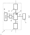
- FIG. 1 illustrates schematically a system for controlling a subsea fluid-actuated device
- FIG. 2 illustrates the fluid flow in the system of FIG. 1 in the initial state
- FIG. 3 illustrates the fluid flow in the system of FIG. 1 in the actuated
- FIG. 4 illustrates a cross sectional side view of a first embodiment of a subsea control valve for controlling the supply of hydraulic fluid to a subsea actuator in the first position;
- FIG. 5 illustrates the subsea control valve of FIG. 4 in the second position
- FIG. 6 illustrates a cross sectional side view of an alternative embodiment of the valve in the first position
- FIG. 7 illustrates the alternative embodiment of the valve of FIG. 6 in the second position
- FIG. 8 illustrates a cross sectional top view of the first embodiment
- FIG. 9 illustrates the control system of the subsea control valve
- FIG. 10 illustrates one example of a subsea fluid-actuated device being controlled by the system of FIG. 1 .
- FIG. 11 illustrates an alternative embodiment of the invention.
- FIG. 1 a system 1 for controlling a subsea fluid-actuated device 4 is shown.
- the system 1 is indicated with a dashed box.
- the system 1 comprises an input fluid system 2 , a return fluid system 3 and a subsea control valve 10 connected to the input fluid system 2 via a first fluid line 6 and to the return fluid system 3 via second fluid line 7 .
- the system 1 is connectable to the fluid-actuated device 4 , to an input fluid source indicated with a dotted box 5 a and to a return fluid reservoir/line to the surface indicated with a dotted box 5 b.
- the fluid-actuated device 4 , the input fluid source 5 a and the return fluid reservoir 5 b are not considered to be a part of the system 1 .
- valve device 10 has been connected to the fluid actuated device 4 via a third fluid line 8 .
- the input fluid system 2 has been connected to the input fluid source 5 a and the return fluid system 3 has been connected to the fluid reservoir 5 b.
- the input fluid system 2 comprises fluid bores, valves etc for supplying fluid from the input fluid source 5 a to the valve 10 .
- the system 2 may comprise selector valves for selecting to supply fluid to the valve 10 from one of several possible sources, for example for redundancy purposes.
- the fluid source 5 a may be located topside (connected to the system 1 via an umbilical) or it may be located on the seabed.
- the return fluid reservoir 5 b may be a fluid reservoir located topside (again connected to the system 1 via the umbilical) or on the seabed.
- the return fluid reservoir 5 b may also be a fluid line which are feed back to the input fluid source 5 a via a pump etc. for increasing the fluid pressure to the fluid pressure of the input fluid line. If the fluid is considered environmentally friendly, the return fluid may also be dumped to sea.
- the input fluid system 2 , the return fluid system 3 , the input fluid source 5 a and the return fluid reservoir 5 b are considered known for the skilled person and will not be described herein further in detail.
- the system 1 is used to control a subsea fluid-actuated device 4 , for example a subsea actuator, which for instance may open and close a valve.
- a subsea fluid-actuated device 4 for example a subsea actuator, which for instance may open and close a valve.
- the device 4 is here a subsea actuator, for example an actuator for moving a subsea valve (not shown) between its open and closed states, typically by means of a linear movement.
- the device 4 is shown to comprise a housing 4 a with a reciprocating piston 4 b provided within the housing 4 a.
- An actuator rod 4 c is provided through the housing 4 a and is connected to the piston 4 b. Together, the actuator rod and actuator piston forms an actuator member.
- a fluid chamber 4 d On a first side of the piston, a fluid chamber 4 d is provided.
- a spring member 4 e is provided on the second side, opposite of the first side. The fluid chamber 4 d would be connected to the above third fluid line 8 .
- most safety critical subsea valves as the main valves closing down the well, are configured to be in its closed state if the fluid pressure in the chamber 4 d is low, for example due to a fluid leakage, an error in the control system etc.
- the spring member 4 e is biased to keep the valve in this closed or initial state.
- the force provided by the spring member 4 e will be counteracted, thereby causing the actuator member of the device 4 to move the valve to its open state.
- the present subsea control system 1 may be used to control not only valves (such as downhole valves, valves in Christmas trees etc), but also other subsea equipment such as chokes, etc.
- the ball valve 10 is in a first position, in which the fluid chamber 4 d of the device 4 is connected via fluid lines 8 and 7 to the return fluid system 3 .
- the fluid pressure is too low to counteract the biasing force of the spring member 4 e , causing the device 4 to be in its initial or non-actuated state.
- the ball valve 10 is in a second position, in which the fluid chamber 4 d of the device 4 is connected via fluid lines 8 and 6 to the input fluid system 2 .
- the fluid pressure is sufficiently high to counteract the biasing force of the spring member 4 e, causing the device 4 to be in its actuated state.
- FIGS. 4 and 5 where a first embodiment of the subsea control valve 10 is shown.
- the purpose of the control valve 10 is to control the supply of hydraulic fluid to the device 4 .
- the direction of the fluid flow between systems 2 , 3 and the device 4 are controlled by the position of the ball valve due to the pressure differences between the fluid in the system 2 and 3 and due to the fluid pressure required to counteract the biasing force of the spring 4 e.
- the fluid-actuated device 4 is biased with a biasing force to an initial state.
- the fluid pressure of the input fluid system 2 is higher than the pressure needed to counteract the biasing force while the fluid pressure of the return fluid system 3 is lower than the pressure needed to counteract the biasing force.
- the control valve 10 comprises a housing 11 with an input fluid line bore 16 , a return fluid line bore 17 and an actuator fluid line bore 18 .
- Each fluid line bore 16 , 17 , 18 may be provided with respective fluid line connectors at the indicated positions 16 A, 17 A, 18 A for connection to the fluid lines 6 , 7 , 8 of FIG. 1 .
- the longitudinal axis of the fluid line bores 16 , 17 , 18 are indicated as dashed lines I 16 , I 17 , I 18 .
- the axis I 16 and I 17 are provided in the same plane.
- the axis I 16 and I 17 are aligned with each other as shown in FIGS. 4 and 5 .
- the axis I 18 is perpendicular to the axis I 16 and I 17 .
- the axis I 16 and I 17 are aligned and within a common plane, however it is possible to envisage the axis not being aligned but still being in a common plane perpendicular to the I 18 .
- the control valve 10 further comprises a ball valve member 20 with a through bore 21 , pivotably connected within the housing 11 between the input fluid line bore 16 , the return fluid line bore 17 and the actuator fluid line bore 18 .
- the ball valve member 20 comprises a shaft 22 protruding out from an opening 13 of the housing 11 .
- the shaft 22 is used to rotate the ball valve member 20 in relation to the housing 11 , for example by means of a motor. This will be described in detail further below.
- a shaft seal 24 is provided between the shaft 22 and the opening 13 of the housing 11 .
- This shaft seal 24 may for example be an O-ring or other suitable type of seal.
- the ball valve member 20 may also comprise a supporting element 23 protruding into the actuator fluid line bore 18 of the housing 11 .
- the supporting element 23 may rotate together with the ball valve member 20 during rotation of the ball valve member 20 .
- the bore 21 is provided through the supporting element 23 .
- the supporting element 23 is formed as a part of the ball valve member 20 , and is arranged at the opposite side of the ball valve member in comparison with the shaft 22 . Hence when the shaft is rotated the support member 23 provide a stabilizing element at the opposite side of the ball valve member.
- a rotation axis of the shaft 21 and hence of the ball valve member 20 is indicated by a dashed line R in FIGS. 4-7 .
- the longitudinal axis I 18 of the actuator fluid line bore 18 is aligned with the rotation axis R of the ball valve member 20 . Accordingly, the fluid line axis I 16 , I 17 are also perpendicular to the rotation axis R.
- the control valve 10 comprises an input side ball seat 30 and a return side ball seat 40 for supporting the ball valve member 20 and sealing elements within the housing 11 .
- the input side ball seat 30 is provided on the same side as the input fluid line bore 16 , and the input fluid line bore 16 is provided as a bore through the input side ball seat 30 .
- the return side ball seat 40 is provided on the same side as the return fluid line bore 17 , and the return fluid line bore 17 is provided as a bore through the return side ball seat 40 .
- the control valve 10 further comprises an input side end element 50 and a return side end element 60 connected to the housing 11 .
- the end elements 50 , 60 may be connected to the housing 11 for example by means of threads, welding etc. Sealing elements 53 , 63 are provided between the respective end elements 50 , 60 and the housing 11 .
- the input fluid line bore 16 is provided as a bore through the input side end element 50 and the return fluid line bore 17 is provided as a bore through the return side end element 60 .
- the input side end element 50 and input side ball seat 30 with their bores then form fluid lines of mainly constant cross sections from the connection point into the ball valve element.
- the end elements 50 , 60 are supporting the ball seats 30 , 40 .
- the input side ball seat 30 comprises an axially protruding section 32 , protruding in the direction towards the input fluid line port 16 A.
- the input side end element 50 comprises an opening 52 for receiving the axially protruding section 32 .
- An input side seal 51 is provided between the axially protruding section 32 and the opening 52 .
- the return side ball seat 40 comprises an axially protruding section 42 , protruding in the direction towards the return fluid line port 17 A.
- the return side end element 60 comprises an opening 62 for receiving the axially protruding section 42 .
- a return side seal 61 is provided between the axially protruding section 32 and the opening 52 .
- An inner annular piston surface 33 is provided in the end of the axially protruding section 32 of the input side ball seat 30 , facing towards the input side end element 50 .
- the input side ball seat 30 also comprises an outer annular piston surface 35 facing towards the input side end element 50 .
- annular piston surface 43 is provided in the end of the axially protruding section 42 of the return side ball seat 40 , facing towards the return side end element 60 .
- the return side ball seat 40 also comprises an outer annular piston surface 45 facing towards the return side end element 60 .
- inner and outer here refers to the axis I 16 and I 17 , where the inner piston surfaces 33 , 43 are closer to the axis I 16 and I 17 than the outer piston surfaces 35 , 45 .
- the input side ball seat 30 and the return side ball seat 40 are biased towards the ball valve member 20 by means of respective spring devices 71 , 72 .
- the input side spring device 71 is provided between the outer annular piston surface 35 of the input side ball seat 30 and the input side end element 50 .
- the return side spring device 72 is provided between the outer annular piston surface 45 of the return side ball seat 40 and the return side end element 60 .
- a first ball valve seal 31 is provided between the input side ball seat 30 and the ball valve member 20 and a second ball valve seal 41 is provided between the return side ball seat 40 and the ball valve member 20 .
- the first ball valve seal 31 is preferably a substantially ring-shaped sealing element having a radius R 31 .
- the second ball valve seal 41 is preferably a substantially ring-shaped sealing element having a radius R 41 .
- the fluid in the input fluid line bore 16 is acting on the inner annular piston surface 33 of the ball seat 30 and that the fluid in the return fluid line bore 17 is acting on the inner annular pistons surface 43 of the ball seat 40 .
- the fluid in the actuator fluid line bore 18 is acting on both of the outer piston surfaces 35 , 45 of the ball seats 30 , 40 .
- FIG. 4 the first position of the ball valve member 20 is shown.
- the actuator fluid line bore 18 and the return fluid line bore 17 are connected to each other via the through bore 21 .
- the fluid pressure in the actuator fluid line bore 18 will be equal to the fluid pressure in the return fluid line bore 17 .
- Both of the outer annular piston surfaces 35 , 45 and the inner annular piston surface 43 will be exposed to the same fluid pressure.
- FIG. 5 the second position of the ball valve member 20 is shown.
- the input fluid line bore 16 and the actuator fluid line bore 18 are connected to each other via the through bore 21 .
- the fluid pressure in the actuator fluid line bore 18 will be equal to the fluid pressure in the input fluid line bore 16 .
- Both of the outer annular piston surfaces 35 , 45 and the inner annular piston surface 33 will be exposed to the same fluid pressure.
- the radius R 31 of the first ball valve seal 31 is equal to the radius R 41 of the second ball valve seal 41 .
- the area of the outer annular piston surface 35 is equal to the area of the outer annular piston surface 45 and the area of the inner annular piston surface 33 is equal to the area of the inner annular piston surface 43 .
- FIG. 8 showing a top view of the control valve of FIG. 5 (i.e. in its second position).
- the bore 21 provided in the ball valve member 20 comprises a first bore section 21 a and a second bore section 21 b provided perpendicular to the first bore section 21 a .
- the bore 21 comprises a third bore section 21 c which is provided centrally downwards to the actuator fluid line bore 18 , i.e. perpendicular to both the first and second bore sections 21 a, 21 b.
- the bore sections 21 b and 21 c are also shown in FIG. 4 and the bore sections 21 a and 21 c are also shown in FIG. 5 .
- the third bore section 21 c is provided through the supporting element 23 of the ball valve member 20 .
- the ball valve member may have only one bore section 21 a which is to be provided in fluid communication with the input fluid line bore 16 in the first state and the return fluid line bore 17 in second state, while the bore section 21 c is always provided in fluid communication with the actuator fluid line bore 18 .
- a rotation of 180° of the ball valve member 20 is necessary to move the control valve 10 between its first and second position, when the input fluid line bore and return fluid line bore are aligned at opposite sides of the ball valve member. It is possible to envisage the input fluid line bore and the return fluid line bore at 90 degrees with each other or another angle but in the same plane, and then the rotation of the ball valve will not necessary need 180 degrees but rather 90 degrees or another other angle.
- the axis I 16 and I 17 of the bores 16 , 17 are coinciding with each other, as shown in FIGS. 4, 5 and 8 .
- the axis I 16 and I 17 of the bores 16 , 17 may for example be oriented with an angle of for example 10°-170° with respect to each other (depending of course of the desired diameter of the bores 16 , 17 and the diameter of the ball member).
- FIGS. 6 and 7 The control valve of FIGS. 6 and 7 is substantially equal to the control valve of FIGS. 4 and 5 . Hence, only the differences will be described below.
- the radius R 31 of the first ball valve seal 31 is smaller than the radius R 41 of the second ball valve seal 41 .
- the area of the input side inner annular piston surface 33 is larger than the area of the return side inner annular piston surface 43 .
- the area of the input side outer annular piston surface 35 is smaller than the area of the return side outer annular piston surface 45 . Accordingly, it is achieved that the fluid pressure, or the difference in fluid pressure, is assisting in the sealing of the control valve by pushing the ball seats 30 , 40 towards the ball valve member 20 .
- the areas of the piston surfaces and the areas within the seals 31 , 41 are different due to the differences in fluid pressure in the input fluid line bore 16 and the return fluid line bore 17 .
- FIG. 9 shows a stepper motor 50 having its rotor connected to the valve shaft 22 of the control valve 10 , and a motor controller 60 for controlling the stepper motor 50 .
- the motor controller is connected to a power source and is controlling the electric power (voltage/current) supplied to the motor 50 by means of a control circuit, for example a digital signal processor.
- the stepper motor 50 does not itself give an accurate feedback with respect to the position of its rotor, hence a sensor device 61 is connected to the motor controller for determining the orientation of the shaft 22 .
- the sensor device 61 may be integrated in the motor controller itself, for example by means of a current sensor measuring the back-emf of the current supplied to the motor.
- the sensor device 61 may comprise one or more position sensors connected to the housing 11 and/or the shaft 22 .
- FIG. 11 showing an alternative embodiment to FIG. 6 . Only the differences will be described here.
- the ball valve member 20 and the shaft 22 are made as one body, alternatively as two bodies fixed to each other.
- connection interface 26 comprises a piston surface 25 exposed to the fluid of the actuator fluid line bore 18 .
- the piston surface 25 and a piston surface 27 of the supporting element 23 being exposed to the fluid of the actuator fluid line bore 18 are provided on opposite sides of the ball valve member 20 .
- a fourth fluid bore section 21 d with a smaller radius than the other bores in the ball valve element may be provided as an extension of the fluid bore section 21 c along the axis 18 A towards the shaft 22 .
- the fourth fluid flow bore section 21 d will contribute to easier or quicker fluid pressure alignment between the side of the ball valve member 20 being adjacent to the shaft 22 and the side of the ball valve member 20 being adjacent to the port 18 A.
- This forth fluid bore section 21 d is not necessary as the fluid pressure from the actuator port 18 A will be transmitted to the piston surface 25 through the cavity in the housing along the ball valve element anyhow. As indicated in FIG. 11 , there is a small gap between the shaft 22 and the ball valve member 20 , forming the piston surface 25 .
Landscapes
- Engineering & Computer Science (AREA)
- General Engineering & Computer Science (AREA)
- Mechanical Engineering (AREA)
- Life Sciences & Earth Sciences (AREA)
- Geology (AREA)
- Mining & Mineral Resources (AREA)
- Physics & Mathematics (AREA)
- Environmental & Geological Engineering (AREA)
- Fluid Mechanics (AREA)
- General Life Sciences & Earth Sciences (AREA)
- Geochemistry & Mineralogy (AREA)
- Taps Or Cocks (AREA)
Abstract
Description
-
- a housing with an input fluid line, an output fluid line and an actuator fluid line;
- a ball valve member with a through bore, pivotably connected within the housing between the input fluid line, the output fluid line and the actuator fluid line, the ball valve member having a first and a second position;
- where the actuator fluid line and the output fluid line are connected to each other via the through bore when the ball valve member is in its first position;
- where the input fluid line and the actuator fluid line are connected to each other via the through bore when the ball valve member is in its second position.
-
- a housing with an input fluid line bore connectable to a input fluid system, a return fluid line bore connectable to a return fluid system and an actuator fluid line bore connectable to the fluid-actuated device;
- a ball valve member with a through bore, pivotably connected within the housing between the input fluid line bore, the return fluid line bore and the actuator fluid line bore, the ball valve member having a first and a second position;
- where the actuator fluid line bore and the return fluid line bore are connected to each other via the through bore when the ball valve member is in its first position, thereby allowing fluid to be returned from the fluid-actuated device to the return fluid system;
- where the input fluid line bore and the actuator fluid line bore are connected to each other via the through bore when the ball valve member is in its second position, thereby allowing fluid to flow from the input fluid system to the fluid-actuated device.
-
- an input side end element and a return side end element connected to the housing;
- where an axially protruding section of the input side ball seat is sealed towards the input side end element by means of an input side seal;
- where an axially protruding section of the return side ball seat is sealed towards the return side end element by means of a return side seal. The input fluid line and return fluid line runs through the input side end element and return side end element respectively. These end elements also comprise sealing elements between them and the housing. The bores of the end elements and the ball seats are formed with a mainly common cross section, similar also to cross section of the bores of the valve element.
-
- a subsea control valve comprising a ball valve member, an input fluid bore, a return fluid bore and an actuator fluid bore,
- an input fluid system connected to the input fluid bore, where the fluid pressure of the input fluid system is configured to be higher than the pressure needed to counteract the biasing force of the actuator member;
- a return fluid system connected to the return fluid bore, where the fluid pressure of the return fluid system is configured to be lower than the pressure needed to counteract the biasing force of the actuator member;
- where the actuator fluid line bore of the valve is connectable to the fluid-actuated device;
- where the actuator fluid line bore and the return fluid line bore are connected to each other when a ball valve member is in its first position; thereby allowing fluid to return from the actuator fluid line bore to the return fluid bore;
- where the input fluid line bore and the actuator fluid line bore are connected to each other when the ball valve member is in its second position, thereby allowing fluid to flow from the input fluid system to the actuator fluid line bore.
-
- a stepper motor connected to the valve shaft;
- a motor controller for controlling the stepper motor;
- a sensor device connected to the motor controller for determining the orientation of the shaft.
Claims (26)
Applications Claiming Priority (3)
| Application Number | Priority Date | Filing Date | Title |
|---|---|---|---|
| NO20161517 | 2016-09-22 | ||
| NO20161517A NO343144B1 (en) | 2016-09-22 | 2016-09-22 | Subsea control valve |
| PCT/EP2017/074023 WO2018055083A1 (en) | 2016-09-22 | 2017-09-22 | Subsea control valve |
Publications (2)
| Publication Number | Publication Date |
|---|---|
| US20190226590A1 US20190226590A1 (en) | 2019-07-25 |
| US10865895B2 true US10865895B2 (en) | 2020-12-15 |
Family
ID=59982362
Family Applications (1)
| Application Number | Title | Priority Date | Filing Date |
|---|---|---|---|
| US16/336,093 Active US10865895B2 (en) | 2016-09-22 | 2017-09-22 | Subsea control valve |
Country Status (5)
| Country | Link |
|---|---|
| US (1) | US10865895B2 (en) |
| EP (1) | EP3516277B1 (en) |
| AU (1) | AU2017331399B2 (en) |
| NO (1) | NO343144B1 (en) |
| WO (1) | WO2018055083A1 (en) |
Cited By (1)
| Publication number | Priority date | Publication date | Assignee | Title |
|---|---|---|---|---|
| US20210108494A1 (en) * | 2018-04-17 | 2021-04-15 | Fmc Technologies, Inc. | Frac Transfer Diverter Valve |
Families Citing this family (2)
| Publication number | Priority date | Publication date | Assignee | Title |
|---|---|---|---|---|
| CN113154089B (en) * | 2021-01-08 | 2025-11-21 | 西安蓝晓科技新材料股份有限公司 | Sealing device and valve body system |
| CN115199562B (en) * | 2022-07-14 | 2026-03-17 | 阳江海上风电实验室 | A reversible pressure-limiting pump suction device suitable for suction cylinder foundations |
Citations (12)
| Publication number | Priority date | Publication date | Assignee | Title |
|---|---|---|---|---|
| US2698731A (en) | 1949-06-29 | 1955-01-04 | Gustave J Koehler | Fluid valve |
| US3118650A (en) | 1961-02-28 | 1964-01-21 | Sargent Engineering Corp | Ball valve construction |
| US3721265A (en) | 1971-04-29 | 1973-03-20 | Fmc Corp | Three-way valve |
| US4552334A (en) | 1984-03-28 | 1985-11-12 | Kawasaki Steel Corporation | Flow change-over valve for the blowing of fluids into molten metal vessel |
| US5285809A (en) | 1991-10-11 | 1994-02-15 | Fukuhara Corporation | Drain discharge device |
| US5944055A (en) | 1997-09-05 | 1999-08-31 | Dicky; Julius | Control valve with swivel connector |
| US20010032951A1 (en) | 1999-10-13 | 2001-10-25 | Robert C. Stewart | Ball valve stem seal arrangement |
| US20020096210A1 (en) | 2001-01-22 | 2002-07-25 | Paul Schwarz | Safety valve and safety valve system |
| US20050252560A1 (en) | 2002-05-01 | 2005-11-17 | Dahl Brothers Canada Limited | Field configurable shut-off valve |
| EP2006586A2 (en) | 2007-06-21 | 2008-12-24 | Tac, Llc | Dynamic ball valve sealing device for three-way valves |
| US20140124195A1 (en) | 2012-04-11 | 2014-05-08 | Mit Holdings Ltd | Apparatus and method to remotely control fluid flow in tubular strings and wellbore annulus |
| US20150226343A1 (en) | 2014-02-11 | 2015-08-13 | Johnson Controls Technology Company | Systems and methods for controlling flow with a 270 degree rotatable valve |
-
2016
- 2016-09-22 NO NO20161517A patent/NO343144B1/en unknown
-
2017
- 2017-09-22 EP EP17777227.4A patent/EP3516277B1/en active Active
- 2017-09-22 AU AU2017331399A patent/AU2017331399B2/en active Active
- 2017-09-22 US US16/336,093 patent/US10865895B2/en active Active
- 2017-09-22 WO PCT/EP2017/074023 patent/WO2018055083A1/en not_active Ceased
Patent Citations (12)
| Publication number | Priority date | Publication date | Assignee | Title |
|---|---|---|---|---|
| US2698731A (en) | 1949-06-29 | 1955-01-04 | Gustave J Koehler | Fluid valve |
| US3118650A (en) | 1961-02-28 | 1964-01-21 | Sargent Engineering Corp | Ball valve construction |
| US3721265A (en) | 1971-04-29 | 1973-03-20 | Fmc Corp | Three-way valve |
| US4552334A (en) | 1984-03-28 | 1985-11-12 | Kawasaki Steel Corporation | Flow change-over valve for the blowing of fluids into molten metal vessel |
| US5285809A (en) | 1991-10-11 | 1994-02-15 | Fukuhara Corporation | Drain discharge device |
| US5944055A (en) | 1997-09-05 | 1999-08-31 | Dicky; Julius | Control valve with swivel connector |
| US20010032951A1 (en) | 1999-10-13 | 2001-10-25 | Robert C. Stewart | Ball valve stem seal arrangement |
| US20020096210A1 (en) | 2001-01-22 | 2002-07-25 | Paul Schwarz | Safety valve and safety valve system |
| US20050252560A1 (en) | 2002-05-01 | 2005-11-17 | Dahl Brothers Canada Limited | Field configurable shut-off valve |
| EP2006586A2 (en) | 2007-06-21 | 2008-12-24 | Tac, Llc | Dynamic ball valve sealing device for three-way valves |
| US20140124195A1 (en) | 2012-04-11 | 2014-05-08 | Mit Holdings Ltd | Apparatus and method to remotely control fluid flow in tubular strings and wellbore annulus |
| US20150226343A1 (en) | 2014-02-11 | 2015-08-13 | Johnson Controls Technology Company | Systems and methods for controlling flow with a 270 degree rotatable valve |
Cited By (2)
| Publication number | Priority date | Publication date | Assignee | Title |
|---|---|---|---|---|
| US20210108494A1 (en) * | 2018-04-17 | 2021-04-15 | Fmc Technologies, Inc. | Frac Transfer Diverter Valve |
| US11898644B2 (en) * | 2018-04-17 | 2024-02-13 | Fmc Technologies, Inc. | Frac transfer diverter valve |
Also Published As
| Publication number | Publication date |
|---|---|
| WO2018055083A1 (en) | 2018-03-29 |
| US20190226590A1 (en) | 2019-07-25 |
| BR112019005272A2 (en) | 2019-06-04 |
| AU2017331399B2 (en) | 2023-08-03 |
| NO343144B1 (en) | 2018-11-19 |
| AU2017331399A1 (en) | 2019-03-14 |
| EP3516277B1 (en) | 2020-07-15 |
| NO20161517A1 (en) | 2018-03-23 |
| EP3516277A1 (en) | 2019-07-31 |
Similar Documents
| Publication | Publication Date | Title |
|---|---|---|
| CN104736858B (en) | Hydraulic system with dynamic seals | |
| US6152172A (en) | Hall effect valve spool position sensor | |
| RU2471959C1 (en) | Two-stage underwater actuating mechanisms | |
| US6575426B2 (en) | Valve system and method | |
| US10371280B2 (en) | Actuator for a valve | |
| US10865895B2 (en) | Subsea control valve | |
| US10669801B2 (en) | Subsea tree override tool apparatus and method | |
| US9470324B2 (en) | Directional valve and method of operation | |
| TWI421426B (en) | Electric needle valve | |
| US11448242B2 (en) | Hydraulic system for use under water with a hydraulic actuating drive | |
| AU2002331034A1 (en) | Valve system and method | |
| US20200166427A1 (en) | Subsea valve, flow system and method of use | |
| US9841119B2 (en) | Pilot valve arrangement | |
| US10352468B2 (en) | Controller apparatus, system and/or method for controlling pressures in a fluid control system | |
| US7913971B2 (en) | Hydraulic override | |
| JP6559108B2 (en) | Switching valve device | |
| BR112014003453B1 (en) | pressure-compensated actuator system to pipeline pressure and method to reduce the force requirements of an actuator in a downhole environment | |
| EP2732128B1 (en) | A solenoid-operated valve | |
| US20180291705A1 (en) | Subsea actuator with magnetic return | |
| US9945494B2 (en) | Pneumatic directional valve and method of operation | |
| GB2472725A (en) | Hydraulic valve with a valve member having different cross-sectional areas | |
| RU2755177C2 (en) | Apparatus for control of downhole fluid medium | |
| GB2565172A (en) | Subsea valve, flow system and method of use |
Legal Events
| Date | Code | Title | Description |
|---|---|---|---|
| FEPP | Fee payment procedure |
Free format text: ENTITY STATUS SET TO UNDISCOUNTED (ORIGINAL EVENT CODE: BIG.); ENTITY STATUS OF PATENT OWNER: LARGE ENTITY |
|
| AS | Assignment |
Owner name: FMC KONGSBERG SUBSEA AS, NORWAY Free format text: ASSIGNMENT OF ASSIGNORS INTEREST;ASSIGNOR:MAGNUS, HEYN HALFDAN;REEL/FRAME:049479/0041 Effective date: 20161010 Owner name: FMC KONGSBERG SUBSEA AS, NORWAY Free format text: ASSIGNMENT OF ASSIGNORS INTEREST;ASSIGNOR:MATHISEN, STIG FREDRIK;REEL/FRAME:049479/0013 Effective date: 20190404 |
|
| STPP | Information on status: patent application and granting procedure in general |
Free format text: APPLICATION DISPATCHED FROM PREEXAM, NOT YET DOCKETED |
|
| STPP | Information on status: patent application and granting procedure in general |
Free format text: DOCKETED NEW CASE - READY FOR EXAMINATION |
|
| STPP | Information on status: patent application and granting procedure in general |
Free format text: NON FINAL ACTION MAILED |
|
| STPP | Information on status: patent application and granting procedure in general |
Free format text: NOTICE OF ALLOWANCE MAILED -- APPLICATION RECEIVED IN OFFICE OF PUBLICATIONS |
|
| STPP | Information on status: patent application and granting procedure in general |
Free format text: PUBLICATIONS -- ISSUE FEE PAYMENT VERIFIED |
|
| STCF | Information on status: patent grant |
Free format text: PATENTED CASE |
|
| MAFP | Maintenance fee payment |
Free format text: PAYMENT OF MAINTENANCE FEE, 4TH YEAR, LARGE ENTITY (ORIGINAL EVENT CODE: M1551); ENTITY STATUS OF PATENT OWNER: LARGE ENTITY Year of fee payment: 4 |
|
| AS | Assignment |
Owner name: TECHNIPFMC NORGE AS, NORWAY Free format text: CHANGE OF NAME;ASSIGNOR:FMC KONGSBERG SUBSEA AS;REEL/FRAME:071648/0304 Effective date: 20250130 |