US10865825B2 - Structural fastener - Google Patents

Structural fastener Download PDF

Info

Publication number
US10865825B2
US10865825B2 US16/040,413 US201816040413A US10865825B2 US 10865825 B2 US10865825 B2 US 10865825B2 US 201816040413 A US201816040413 A US 201816040413A US 10865825 B2 US10865825 B2 US 10865825B2
Authority
US
United States
Prior art keywords
nut
sectioned
threaded
sections
cage
Prior art date
Legal status (The legal status is an assumption and is not a legal conclusion. Google has not performed a legal analysis and makes no representation as to the accuracy of the status listed.)
Expired - Fee Related, expires
Application number
US16/040,413
Other versions
US20200025235A1 (en
Inventor
Michael Walter Smith
Daniel James Dickinson
Current Assignee (The listed assignees may be inaccurate. Google has not performed a legal analysis and makes no representation or warranty as to the accuracy of the list.)
Mag Daddy LLC
Original Assignee
Mag Daddy LLC
Priority date (The priority date is an assumption and is not a legal conclusion. Google has not performed a legal analysis and makes no representation as to the accuracy of the date listed.)
Filing date
Publication date
Application filed by Mag Daddy LLC filed Critical Mag Daddy LLC
Priority to US16/040,413 priority Critical patent/US10865825B2/en
Publication of US20200025235A1 publication Critical patent/US20200025235A1/en
Priority to US16/779,870 priority patent/US11655841B2/en
Application granted granted Critical
Publication of US10865825B2 publication Critical patent/US10865825B2/en
Priority to US17/405,030 priority patent/US20210404504A1/en
Expired - Fee Related legal-status Critical Current
Adjusted expiration legal-status Critical

Links

Images

Classifications

    • FMECHANICAL ENGINEERING; LIGHTING; HEATING; WEAPONS; BLASTING
    • F16ENGINEERING ELEMENTS AND UNITS; GENERAL MEASURES FOR PRODUCING AND MAINTAINING EFFECTIVE FUNCTIONING OF MACHINES OR INSTALLATIONS; THERMAL INSULATION IN GENERAL
    • F16BDEVICES FOR FASTENING OR SECURING CONSTRUCTIONAL ELEMENTS OR MACHINE PARTS TOGETHER, e.g. NAILS, BOLTS, CIRCLIPS, CLAMPS, CLIPS OR WEDGES; JOINTS OR JOINTING
    • F16B37/00Nuts or like thread-engaging members
    • F16B37/08Quickly-detachable or mountable nuts, e.g. consisting of two or more parts; Nuts movable along the bolt after tilting the nut
    • F16B37/0871Quickly-detachable or mountable nuts, e.g. consisting of two or more parts; Nuts movable along the bolt after tilting the nut engaging the bolt laterally, i.e. without the need to engage the end of the bolt
    • F16B37/0885Quickly-detachable or mountable nuts, e.g. consisting of two or more parts; Nuts movable along the bolt after tilting the nut engaging the bolt laterally, i.e. without the need to engage the end of the bolt in two halves hingedly connected
    • FMECHANICAL ENGINEERING; LIGHTING; HEATING; WEAPONS; BLASTING
    • F16ENGINEERING ELEMENTS AND UNITS; GENERAL MEASURES FOR PRODUCING AND MAINTAINING EFFECTIVE FUNCTIONING OF MACHINES OR INSTALLATIONS; THERMAL INSULATION IN GENERAL
    • F16BDEVICES FOR FASTENING OR SECURING CONSTRUCTIONAL ELEMENTS OR MACHINE PARTS TOGETHER, e.g. NAILS, BOLTS, CIRCLIPS, CLAMPS, CLIPS OR WEDGES; JOINTS OR JOINTING
    • F16B37/00Nuts or like thread-engaging members
    • F16B37/08Quickly-detachable or mountable nuts, e.g. consisting of two or more parts; Nuts movable along the bolt after tilting the nut
    • F16B37/0807Nuts engaged from the end of the bolt, e.g. axially slidable nuts
    • F16B37/0821Nuts engaged from the end of the bolt, e.g. axially slidable nuts in two halves pivotally connected
    • FMECHANICAL ENGINEERING; LIGHTING; HEATING; WEAPONS; BLASTING
    • F16ENGINEERING ELEMENTS AND UNITS; GENERAL MEASURES FOR PRODUCING AND MAINTAINING EFFECTIVE FUNCTIONING OF MACHINES OR INSTALLATIONS; THERMAL INSULATION IN GENERAL
    • F16BDEVICES FOR FASTENING OR SECURING CONSTRUCTIONAL ELEMENTS OR MACHINE PARTS TOGETHER, e.g. NAILS, BOLTS, CIRCLIPS, CLAMPS, CLIPS OR WEDGES; JOINTS OR JOINTING
    • F16B37/00Nuts or like thread-engaging members
    • F16B37/08Quickly-detachable or mountable nuts, e.g. consisting of two or more parts; Nuts movable along the bolt after tilting the nut
    • F16B37/0871Quickly-detachable or mountable nuts, e.g. consisting of two or more parts; Nuts movable along the bolt after tilting the nut engaging the bolt laterally, i.e. without the need to engage the end of the bolt
    • F16B37/0892Quickly-detachable or mountable nuts, e.g. consisting of two or more parts; Nuts movable along the bolt after tilting the nut engaging the bolt laterally, i.e. without the need to engage the end of the bolt in two or more pieces, e.g. assemblies made by two C-shaped nuts mutually interlocked, or retained by an additional member
    • FMECHANICAL ENGINEERING; LIGHTING; HEATING; WEAPONS; BLASTING
    • F16ENGINEERING ELEMENTS AND UNITS; GENERAL MEASURES FOR PRODUCING AND MAINTAINING EFFECTIVE FUNCTIONING OF MACHINES OR INSTALLATIONS; THERMAL INSULATION IN GENERAL
    • F16BDEVICES FOR FASTENING OR SECURING CONSTRUCTIONAL ELEMENTS OR MACHINE PARTS TOGETHER, e.g. NAILS, BOLTS, CIRCLIPS, CLAMPS, CLIPS OR WEDGES; JOINTS OR JOINTING
    • F16B37/00Nuts or like thread-engaging members
    • F16B37/08Quickly-detachable or mountable nuts, e.g. consisting of two or more parts; Nuts movable along the bolt after tilting the nut

Definitions

  • the invention relates generally to devices for fastening objects, and more particularly to a fastener and strut hangers to secure construction components or to attach onto an engagement structure, such as a chassis, a strut, a hollow substrate, a wall, a plate or any suitable surface.
  • an engagement structure such as a chassis, a strut, a hollow substrate, a wall, a plate or any suitable surface.
  • a number of devices and fasteners in building construction are currently available to secure cables or for fastening threaded rods, struts, panels, body panels, building structure, and electrical conduit to the chassis or frame of a building.
  • spring nuts and other devices are used to secure bolts and threaded rods to a strut or truss.
  • Clamps and cable ties are used to secure cables in electrical wiring and boxes.
  • a strut refers to a u-shaped bracket having holes to allow for attachment at various points and to facilitate a variety of construction situations.
  • the chassis of the building may include any substrate, plate, roof or ceiling support, structural framework, chassis component or subcomponent, support component, wall or any suitable object or combination.
  • Attaching conduit, electrical boxes, wires or cables to a building structure, electrical box or body panel typically requires securing threaded rods with two bolts to support wires, cable clamps, electrical boxes, screw in cable clamps, straps, tape or clips already fastened to a wire assembly.
  • At least some of the fasteners require extended height or blind insertion and installation of the fasteners in difficult locations because the installer is not able to fully view the fastener or the mounting point on the body panel.
  • These known fasteners require fastening with a wrench, ratchet or screw driver and thus are cumbersome and difficult to install, especially in inaccessible areas. Nor can they be installed without a wrench, ratchet or screw driver for example on an electrical box, conduit or in automobile environments that can be difficult. Further, replacement of an installed, broken nut, rod or strut requires removal and can again be difficult and time consuming.
  • Conventional nuts such as nuts and spring nuts are placed by hand into a channel of strut to attach other structural components (e.g., another strut, cable hanger, bracket, etc.) to the strut such as a conventional nut described in U.S. Pat. No. 9,103,365 incorporated by reference.
  • two conventional nuts on either side of the strut are required to clamp the rod in place into the strut.
  • conventional nuts require the installer to hold the nuts in place with one hand while rotating the threaded rod, then threading the second nut with their other hand, requiring two hands.
  • a spring nut requires two hands since an installer inserts the nut and the spring between the channel back and the channel opening while rotating the threaded rod with their other hand.
  • FIG. 1 is an exploded view of a multi sectioned nut according to one embodiment
  • FIG. 2 is a partially assembled view of a multi sectioned nut operable to attach to a threaded fastener according to another embodiment
  • FIG. 3 is a view of a strut and sectioned nut assembly according to one embodiment
  • FIG. 4 is a perspective view of a plurality of multi sectioned threaded nut sections according to one embodiment.
  • FIG. 5 is a perspective view of a cage according to one embodiment
  • FIG. 6 is a exploded view of a plurality of multi sectioned threaded nut sections according to one embodiment
  • FIG. 7 is a view of a partially assembled multi sectioned nut assembly
  • FIG. 8 is a side view of a plurality of multi sectioned threaded nut sections according to one embodiment
  • FIG. 9 is a cross section view of a plurality of multi sectioned threaded nut sections according to one embodiment
  • FIG. 10 is a side view of a strut and sectioned nut assembly according to one embodiment
  • FIG. 11 is a top view of a strut and sectioned nut assembly according to one embodiment.
  • FIG. 12 is another side view of a strut and sectioned nut assembly according to one embodiment.
  • a multi sectioned nut is operable to attach to a threaded fastener.
  • the multi sectioned nut includes a plurality of multi sectioned threaded nut sections and a turn-lock formed on at least one end, such as a top, of the plurality of threaded nut sections.
  • a cage is detachably coupled to the plurality of nut sections operable to allow the nut sections spring open on a side opposite the cage to allow the threaded fastener to pass through.
  • the turn-lock is inserted into a strut slot and rotated to removably attach to the strut slot.
  • the multi sectioned nut may include at least two sections however multiple sections such as 3, 4, 5, 6, 7, 8 or any suitable number sections are contemplated.
  • the turn-lock has a rectangular shape with rounded edges, to avoid radius interference.
  • the turn lock may have a length that is greater than width thus forms the rectangular shape.
  • the width of the turn-lock is sized to be slightly narrower than the slot width to permit insertion of the turn-lock into the slot.
  • the turn lock is then rotated 90 degrees such that the length of turn lock is greater than the slot width thus securely engaging the turn lock with the strut.
  • the multi sectioned threaded nut sections and the cage are comprised of at least one of: zinc die cast, machine steel, cast plastic or powdered metal, cindered (pressing powder together), plastic, vinyl, rubber, plastisol, plastic, acetal, polyacetal, polyoxymethylene, nylon, fiberglass, carbon fiber or similar materials.
  • the locking tabs provide a type of hinge between the plurality of multi sectioned threaded nut sections. The locking tabs stabilize and retain the multi sectioned threaded nut sections.
  • wings on each of the ends of the cage engage corresponding depressions on open ends of the multi sectioned threaded nut sections to stabilize and retain the cage on the multi sectioned threaded nut sections.
  • the multi sectioned nut may be rotated on the threaded fastener to continuously adapt to variations in height in order to adjust the position of the strut.
  • the threaded fastener may be rotated on the threaded fastener to continuously adapt to variations in height in order to adjust the position of the strut.
  • the multi sectioned nut permits relatively easy insertion of the strut into a building chassis, pillar, structure, door, roof or suitable panel while providing a relatively high level of strength and support. Assembly of the multi sectioned nut onto the threaded fastener or rod is very easy and requires no or a relatively low level of installation effort and as a result provides many ergonomic advantages.
  • the multi sectioned nut eliminates the need for threading a nut on a long threaded rod, and thus significantly reduces the time to attach the nut to the threaded rod assembly. Also, the installer can attach the multi sectioned nut with one hand whereas the prior art conventional nuts require two hands to hold the nuts and the structural construction member.
  • the relatively easy attachment is particularly advantageous for operators who repetitively install multi sectioned nuts onto the building chassis.
  • the relatively easy installation required for inserting the multi sectioned nut into the building chassis may result in fewer injuries to the assembly workers, including injuries related to repetitive stress syndrome.
  • Further by selecting a single multi sectioned nut or reducing the number of different fasteners for different strut lengths and thicknesses confusion during assembly is eliminated since the same type or a reduced number of fasteners may be used for all or most struts. Thus, an electrician, installer, or assembly worker need not worry about selecting the wrong fastener.
  • the multi section nut is easily rotated in the strut slot and the multi section nut may be easily rotated for the desired position on the threaded fastener.
  • the multi sectioned nut may also fasten to plastic and/or metal engagement structures.
  • the multi sectioned nut may be made of anti-corrosive material such as plastic or treated metal to provide long reliable service life.
  • the multi sectioned nut is relatively easy to manufacture using relatively inexpensive manufacturing processes and materials such as casting steel alloy.
  • the use of the multi sectioned nut decreases installation effort and time, assembly and construction costs, increases worker productivity and efficiency, improves reliability and quality and decreases overall assembly, warranty and maintenance costs.
  • the multi sectioned nut improves reliability both in the short term and in the long term, while further improving safety and quality.
  • FIG. 1 is an exploded view of a multi sectioned nut 10 according to one embodiment.
  • the multi sectioned nut 10 includes a plurality of multi sectioned threaded nut sections 20 and a band 50 .
  • the plurality of multi sectioned nut sections 20 includes two multi sectioned threaded nut sections 30 , 40 although any suitable number of sections is contemplated such as 3, 4, 5, 6, 8 or more.
  • FIG. 2 is a partially assembled view of a multi sectioned nut 10 operable to attach to a threaded fastener 60 according to another embodiment.
  • the multi sectioned nut 10 is operable to attach to the threaded fastener 60 by inserting into, pushing and then spreading open the respective tapered sections 32 , 42 of threaded nut sections 30 , 40 creating an opening for the threaded fastener 60 to pass through.
  • FIG. 5 is a perspective view of a cage 50 according to one embodiment.
  • the cage 50 is detachably coupled to the plurality of nut sections 20 ( 30 , 40 ) and is operable to spring open on an open side of nut sections 30 , 40 opposite the cage to allow the threaded fastener 60 to pass into tapered sections 32 , 42 .
  • the multi sectioned nut 10 includes a plurality of multi sectioned threaded nut sections 20 ( 30 , 40 ) and a turn-lock 34 , 44 formed on at least one end of the plurality of threaded nut sections.
  • FIG. 3 is a view of a strut 300 and sectioned nut assembly according to one embodiment.
  • the turn lock 34 , 44 is shown in the strut slot 310 before turning in an unlocked position.
  • the turn-lock 34 , 44 is inserted into a strut slot 310 and the turn lock 34 , 44 is rotated to a locked position to removably attach to the strut slot 310 .
  • the turn-lock 34 , 44 may be rotated 90 degrees according to one embodiment into the locked position.
  • FIG. 4 is a perspective view of a plurality of multi sectioned threaded nut sections 30 , 40 according to one embodiment and further showing the turn lock 34 , 44 details.
  • Turn lock 34 further includes a flange 400 to engage an edge portion of the strut slot 310 when in a locked position, and groove 410 , 430 to accommodate a lip or edge of the strut slot 310 to permit sufficient clearance of the strut slot 310 rim when rotated.
  • Turn lock 44 further includes a flange 420 to engage a portion of the strut slot 310 when in a locked position, and groove 430 to permit sufficient clearance of the strut slot 310 rim.
  • the groove 410 , 430 form a boss or stand-off width similar to or slightly smaller than the width of the strut slot 310 in order to sufficiently engage the strut slot and provide the desired amount of attachment or detachment force when in a locked position.
  • the turn-lock 34 , 44 has rectangular shaped flanges 400 , 420 with rounded edges, to avoid radius interference.
  • the turn lock 34 , 44 may have a length that is greater than width thus forming the rectangular shape.
  • the width of the turn-lock 34 , 44 is sized such slightly narrower than the slot width to permit insertion of the turn-lock into the slot as shown in FIG. 3 .
  • the turn lock 34 , 44 is then rotated 90 degrees such that the length of turn lock 34 , 44 is greater than the slot width thus securely engaging the turn lock with the strut.
  • the rounded edges are sized such that a radius from the center of the turn lock to the closest edge of the strut permits rotation in the channel. The turn lock to rotate 90 degrees while maximizing length and thus strength.
  • FIG. 5 is a perspective view of a cage 50 according to one embodiment.
  • wings 500 , 510 on each of the ends of the cage 50 engage corresponding depressions 512 (shown in FIG. 2 ) and 502 (not shown) on open ends of the multi sectioned threaded nut sections to stabilize and retain the cage 50 on the multi sectioned threaded nut sections 30 , 40 .
  • the wings 500 , 510 include corresponding prongs 514 , 516 to engage the corresponding depressions 512 (shown in FIG. 2 ) and 502 (not shown) thus preventing the nut sections 30 , 40 from escaping the cage 50 .
  • cage 50 provides a springing hold on the nut sections 30 , 40 to allow nut sections 30 , 40 to open and then close and thus enclose the nut sections 30 , 40 together and to further allow the threads 120 on the nut sections to engage the threads 200 on the threaded fastener 60 .
  • the multi sectioned threaded nut sections 20 , 32 , 42 and the cage 50 may be comprised of at least one of: zinc die cast, machine steel, cast plastic or powdered metal, cindered (pressing powder together), plastic, vinyl, rubber, plastisol, plastic, acetal, polyacetal, polyoxymethylene, nylon, fiberglass, carbon fiber, or similar materials.
  • FIG. 6 is a exploded view of a plurality of multi sectioned threaded nut sections according to one embodiment prior to attachment of the cage 50 .
  • the locking tabs 100 , 110 provide a hinge function for the plurality of multi sectioned threaded nut sections 30 , 40 to permit opening of the nut sections 30 , 40 as described above.
  • Locking tab 110 may be a prong having a curve as shown in FIG. 6 to permit rotation about and pivoting between the nut sections 30 , 40 .
  • Corresponding locking tab 100 has a corresponding shape and form to rotatable engage locking tab prong 110 .
  • FIG. 7 is a view of a partially assembled multi sectioned nut assembly.
  • nut section 30 has a tongue 100 or tab and nut section 40 has a locking groove 110 .
  • the locking tabs 100 , 110 are shown aligning and keeping nut sections 30 , 40 while providing an opening suitable for threaded rod 60 .
  • FIG. 8 is a side view of a plurality of multi sectioned threaded nut sections according to one embodiment showing the locking tabs 100 , 110 coupled.
  • the locking tabs 100 , 110 stabilize and retain the multi sectioned threaded nut sections 30 , 40 when in a closed position such as when in compression with the cage 50 .
  • the sections 30 , 40 form a stable joint and thus do not slip or slide apart axially either when the nut sections 30 , 40 are in either open or closed positions.
  • FIG. 9 is a cross section view of a plurality of multi sectioned threaded 120 nut section 40 according to one embodiment. Locking tab 100 is shown.
  • FIG. 10 is a side view of a strut and sectioned nut 10 assembly attached to a structural member 300 according to one embodiment.
  • the nut may be inserted into any suitable slot 310 of the structural member 300 .
  • FIG. 11 is a top view of a strut and sectioned nut assembly 10 attached to a structural member 300 according to one embodiment.
  • the nut assembly 10 is shown in the locked position.
  • the nut may be inserted into any suitable slot 310 of the structural member 300 .
  • FIG. 12 is another side view of a strut and sectioned nut assembly according to the embodiment of FIG. 11 rotated 90 degrees.
  • the multi sectioned nut 10 may be rotated to continuously adapt to variations in height in order to adjust the position of the strut 300 .
  • the height of the strut 300 may be raised or lowered simply by rotating the nut 10 from the strut 300 and adjusting the position of the rod 60 and rotating the nut 10 into a locked position.
  • the position of the nut 10 may be raised or lowered by rotating the nut 10 along the rod 60 or by pushing the nut 10 out then snapping it back in at the desired rod 60 height or position.
  • only a single type or size of multi sectioned nut 10 need be used with a building, chassis or application even if different strut attachment lengths are required at different attachment points.
  • the multi sectioned nut permits relatively easy insertion of the strut into a building chassis, pillar, structure, door, roof or suitable panel while providing a relatively high level of strength and support. Assembly of the multi sectioned nut 20 onto the threaded fastener or rod 60 is very easy and requires no or a relatively low level of installation effort and as a result provides many ergonomic advantages.
  • the multi sectioned nut 10 eliminates the need for threading a conventional unsectioned nut on a long threaded rod, and thus significantly reduces the nut—threaded rod assembly. Also, the installer can attach the multi sectioned nut 10 with one hand whereas the prior art conventional nuts require two hands to hold the nut and the structural construction member.

Landscapes

  • Engineering & Computer Science (AREA)
  • General Engineering & Computer Science (AREA)
  • Mechanical Engineering (AREA)
  • Mutual Connection Of Rods And Tubes (AREA)

Abstract

A multi sectioned nut is operable to attach to a threaded fastener. The multi sectioned nut includes a plurality of multi sectioned threaded nut sections and a turn-lock formed on at least one end of the plurality of threaded nut sections. A cage is detachably coupled to the plurality of nut sections operable to spring open on a side opposite the cage to allow the threaded fastener to pass through. The turn-lock is inserted into a strut slot and rotated to removably attach to the strut slot. According to one embodiment, the multi sectioned nut may include at least two sections.

Description

FIELD OF THE INVENTION
The invention relates generally to devices for fastening objects, and more particularly to a fastener and strut hangers to secure construction components or to attach onto an engagement structure, such as a chassis, a strut, a hollow substrate, a wall, a plate or any suitable surface.
BACKGROUND OF THE INVENTION
A number of devices and fasteners in building construction are currently available to secure cables or for fastening threaded rods, struts, panels, body panels, building structure, and electrical conduit to the chassis or frame of a building. For example, spring nuts and other devices are used to secure bolts and threaded rods to a strut or truss. Clamps and cable ties are used to secure cables in electrical wiring and boxes. As used herein, a strut refers to a u-shaped bracket having holes to allow for attachment at various points and to facilitate a variety of construction situations. The chassis of the building may include any substrate, plate, roof or ceiling support, structural framework, chassis component or subcomponent, support component, wall or any suitable object or combination.
Attaching conduit, electrical boxes, wires or cables to a building structure, electrical box or body panel typically requires securing threaded rods with two bolts to support wires, cable clamps, electrical boxes, screw in cable clamps, straps, tape or clips already fastened to a wire assembly. At least some of the fasteners require extended height or blind insertion and installation of the fasteners in difficult locations because the installer is not able to fully view the fastener or the mounting point on the body panel. These known fasteners require fastening with a wrench, ratchet or screw driver and thus are cumbersome and difficult to install, especially in inaccessible areas. Nor can they be installed without a wrench, ratchet or screw driver for example on an electrical box, conduit or in automobile environments that can be difficult. Further, replacement of an installed, broken nut, rod or strut requires removal and can again be difficult and time consuming.
Conventional nuts such as nuts and spring nuts are placed by hand into a channel of strut to attach other structural components (e.g., another strut, cable hanger, bracket, etc.) to the strut such as a conventional nut described in U.S. Pat. No. 9,103,365 incorporated by reference. Further, two conventional nuts on either side of the strut are required to clamp the rod in place into the strut. However conventional nuts require the installer to hold the nuts in place with one hand while rotating the threaded rod, then threading the second nut with their other hand, requiring two hands. A spring nut requires two hands since an installer inserts the nut and the spring between the channel back and the channel opening while rotating the threaded rod with their other hand.
BRIEF DESCRIPTION OF THE DRAWINGS
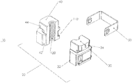
FIG. 1 is an exploded view of a multi sectioned nut according to one embodiment;
FIG. 2 is a partially assembled view of a multi sectioned nut operable to attach to a threaded fastener according to another embodiment;
FIG. 3 is a view of a strut and sectioned nut assembly according to one embodiment;
FIG. 4 is a perspective view of a plurality of multi sectioned threaded nut sections according to one embodiment; and
FIG. 5 is a perspective view of a cage according to one embodiment;
FIG. 6 is a exploded view of a plurality of multi sectioned threaded nut sections according to one embodiment;
FIG. 7 is a view of a partially assembled multi sectioned nut assembly
FIG. 8 is a side view of a plurality of multi sectioned threaded nut sections according to one embodiment;
FIG. 9 is a cross section view of a plurality of multi sectioned threaded nut sections according to one embodiment;
FIG. 10 is a side view of a strut and sectioned nut assembly according to one embodiment;
FIG. 11 is a top view of a strut and sectioned nut assembly according to one embodiment; and
FIG. 12 is another side view of a strut and sectioned nut assembly according to one embodiment.
DETAILED DESCRIPTION OF THE PREFERRED EMBODIMENTS
A multi sectioned nut is operable to attach to a threaded fastener. The multi sectioned nut includes a plurality of multi sectioned threaded nut sections and a turn-lock formed on at least one end, such as a top, of the plurality of threaded nut sections. A cage is detachably coupled to the plurality of nut sections operable to allow the nut sections spring open on a side opposite the cage to allow the threaded fastener to pass through. The turn-lock is inserted into a strut slot and rotated to removably attach to the strut slot. According to one embodiment, the multi sectioned nut may include at least two sections however multiple sections such as 3, 4, 5, 6, 7, 8 or any suitable number sections are contemplated.
According to one embodiment, the turn-lock has a rectangular shape with rounded edges, to avoid radius interference. The turn lock may have a length that is greater than width thus forms the rectangular shape. The width of the turn-lock is sized to be slightly narrower than the slot width to permit insertion of the turn-lock into the slot. The turn lock is then rotated 90 degrees such that the length of turn lock is greater than the slot width thus securely engaging the turn lock with the strut.
The multi sectioned threaded nut sections and the cage are comprised of at least one of: zinc die cast, machine steel, cast plastic or powdered metal, cindered (pressing powder together), plastic, vinyl, rubber, plastisol, plastic, acetal, polyacetal, polyoxymethylene, nylon, fiberglass, carbon fiber or similar materials. The locking tabs provide a type of hinge between the plurality of multi sectioned threaded nut sections. The locking tabs stabilize and retain the multi sectioned threaded nut sections.
According to one embodiment, wings on each of the ends of the cage engage corresponding depressions on open ends of the multi sectioned threaded nut sections to stabilize and retain the cage on the multi sectioned threaded nut sections.
During installation, the multi sectioned nut may be rotated on the threaded fastener to continuously adapt to variations in height in order to adjust the position of the strut. Thus, only a single multi sectioned nut need be used with a building, chassis or application even if different strut attachment lengths are required at different attachment points.
The multi sectioned nut permits relatively easy insertion of the strut into a building chassis, pillar, structure, door, roof or suitable panel while providing a relatively high level of strength and support. Assembly of the multi sectioned nut onto the threaded fastener or rod is very easy and requires no or a relatively low level of installation effort and as a result provides many ergonomic advantages. The multi sectioned nut eliminates the need for threading a nut on a long threaded rod, and thus significantly reduces the time to attach the nut to the threaded rod assembly. Also, the installer can attach the multi sectioned nut with one hand whereas the prior art conventional nuts require two hands to hold the nuts and the structural construction member. Also, conventional nuts do not self align the nut with the slot opening on the channel back, so readjustment of the first and second nuts is required to align the rod to pass through the slot. In contrast, the multi sectioned nut is automatically self aligned because the turn lock is coupled to the slot and thus no alignment of the rod is required with the slot.
The relatively easy attachment is particularly advantageous for operators who repetitively install multi sectioned nuts onto the building chassis. The relatively easy installation required for inserting the multi sectioned nut into the building chassis may result in fewer injuries to the assembly workers, including injuries related to repetitive stress syndrome. Further by selecting a single multi sectioned nut or reducing the number of different fasteners for different strut lengths and thicknesses, confusion during assembly is eliminated since the same type or a reduced number of fasteners may be used for all or most struts. Thus, an electrician, installer, or assembly worker need not worry about selecting the wrong fastener.
The relatively high level of strength, characteristic of the multi sectioned nut, securely attaches to the building or chassis. Further, the multi sectioned nut quickly and easily adjusts to the threaded fastener and minimizes long tedious threading of nuts on the threaded fastener, stripping threads, rounding hex nut edges, flexing of the threaded fastener and structural members, pushing and bending by operators, vibration and thermal expansion. For example, since conventional top and bottom nuts between the strut are required to clamp the strut, changes in length of the strut or rod requires untightening and re-tightening of the nuts. In contrast, the multi section nut is easily rotated in the strut slot and the multi section nut may be easily rotated for the desired position on the threaded fastener. The multi sectioned nut may also fasten to plastic and/or metal engagement structures. The multi sectioned nut may be made of anti-corrosive material such as plastic or treated metal to provide long reliable service life.
Yet another advantage is that the multi sectioned nut is relatively easy to manufacture using relatively inexpensive manufacturing processes and materials such as casting steel alloy. The use of the multi sectioned nut decreases installation effort and time, assembly and construction costs, increases worker productivity and efficiency, improves reliability and quality and decreases overall assembly, warranty and maintenance costs. The multi sectioned nut improves reliability both in the short term and in the long term, while further improving safety and quality.
FIG. 1 is an exploded view of a multi sectioned nut 10 according to one embodiment. The multi sectioned nut 10 includes a plurality of multi sectioned threaded nut sections 20 and a band 50. According to one embodiment the plurality of multi sectioned nut sections 20 includes two multi sectioned threaded nut sections 30, 40 although any suitable number of sections is contemplated such as 3, 4, 5, 6, 8 or more.
FIG. 2 is a partially assembled view of a multi sectioned nut 10 operable to attach to a threaded fastener 60 according to another embodiment. The multi sectioned nut 10 is operable to attach to the threaded fastener 60 by inserting into, pushing and then spreading open the respective tapered sections 32, 42 of threaded nut sections 30, 40 creating an opening for the threaded fastener 60 to pass through.
FIG. 5 is a perspective view of a cage 50 according to one embodiment. The cage 50 is detachably coupled to the plurality of nut sections 20 (30, 40) and is operable to spring open on an open side of nut sections 30, 40 opposite the cage to allow the threaded fastener 60 to pass into tapered sections 32, 42. The multi sectioned nut 10 includes a plurality of multi sectioned threaded nut sections 20 (30, 40) and a turn- lock 34, 44 formed on at least one end of the plurality of threaded nut sections.
FIG. 3 is a view of a strut 300 and sectioned nut assembly according to one embodiment. As shown the turn lock 34, 44 is shown in the strut slot 310 before turning in an unlocked position. The turn- lock 34, 44 is inserted into a strut slot 310 and the turn lock 34, 44 is rotated to a locked position to removably attach to the strut slot 310. The turn- lock 34, 44 may be rotated 90 degrees according to one embodiment into the locked position.
FIG. 4 is a perspective view of a plurality of multi sectioned threaded nut sections 30, 40 according to one embodiment and further showing the turn lock 34, 44 details. Turn lock 34 further includes a flange 400 to engage an edge portion of the strut slot 310 when in a locked position, and groove 410, 430 to accommodate a lip or edge of the strut slot 310 to permit sufficient clearance of the strut slot 310 rim when rotated. Turn lock 44 further includes a flange 420 to engage a portion of the strut slot 310 when in a locked position, and groove 430 to permit sufficient clearance of the strut slot 310 rim. The groove 410, 430 form a boss or stand-off width similar to or slightly smaller than the width of the strut slot 310 in order to sufficiently engage the strut slot and provide the desired amount of attachment or detachment force when in a locked position. According to one embodiment, the turn- lock 34, 44 has rectangular shaped flanges 400, 420 with rounded edges, to avoid radius interference. The turn lock 34, 44 may have a length that is greater than width thus forming the rectangular shape. The width of the turn- lock 34, 44 is sized such slightly narrower than the slot width to permit insertion of the turn-lock into the slot as shown in FIG. 3. The turn lock 34, 44 is then rotated 90 degrees such that the length of turn lock 34, 44 is greater than the slot width thus securely engaging the turn lock with the strut. The rounded edges are sized such that a radius from the center of the turn lock to the closest edge of the strut permits rotation in the channel. The turn lock to rotate 90 degrees while maximizing length and thus strength.
FIG. 5 is a perspective view of a cage 50 according to one embodiment. According to one embodiment, wings 500, 510 on each of the ends of the cage 50 engage corresponding depressions 512 (shown in FIG. 2) and 502 (not shown) on open ends of the multi sectioned threaded nut sections to stabilize and retain the cage 50 on the multi sectioned threaded nut sections 30, 40. According to one embodiment, the wings 500, 510 include corresponding prongs 514, 516 to engage the corresponding depressions 512 (shown in FIG. 2) and 502 (not shown) thus preventing the nut sections 30, 40 from escaping the cage 50. Thus cage 50 provides a springing hold on the nut sections 30, 40 to allow nut sections 30, 40 to open and then close and thus enclose the nut sections 30, 40 together and to further allow the threads 120 on the nut sections to engage the threads 200 on the threaded fastener 60.
The multi sectioned threaded nut sections 20, 32, 42 and the cage 50 may be comprised of at least one of: zinc die cast, machine steel, cast plastic or powdered metal, cindered (pressing powder together), plastic, vinyl, rubber, plastisol, plastic, acetal, polyacetal, polyoxymethylene, nylon, fiberglass, carbon fiber, or similar materials.
FIG. 6 is a exploded view of a plurality of multi sectioned threaded nut sections according to one embodiment prior to attachment of the cage 50. The locking tabs 100, 110 provide a hinge function for the plurality of multi sectioned threaded nut sections 30, 40 to permit opening of the nut sections 30, 40 as described above. Locking tab 110 may be a prong having a curve as shown in FIG. 6 to permit rotation about and pivoting between the nut sections 30, 40. Corresponding locking tab 100 has a corresponding shape and form to rotatable engage locking tab prong 110.
FIG. 7 is a view of a partially assembled multi sectioned nut assembly. According to one embodiment, nut section 30 has a tongue 100 or tab and nut section 40 has a locking groove 110. The locking tabs 100, 110 are shown aligning and keeping nut sections 30, 40 while providing an opening suitable for threaded rod 60.
FIG. 8 is a side view of a plurality of multi sectioned threaded nut sections according to one embodiment showing the locking tabs 100, 110 coupled. The locking tabs 100, 110 stabilize and retain the multi sectioned threaded nut sections 30, 40 when in a closed position such as when in compression with the cage 50. As a result, the sections 30, 40 form a stable joint and thus do not slip or slide apart axially either when the nut sections 30, 40 are in either open or closed positions.
FIG. 9 is a cross section view of a plurality of multi sectioned threaded 120 nut section 40 according to one embodiment. Locking tab 100 is shown.
FIG. 10 is a side view of a strut and sectioned nut 10 assembly attached to a structural member 300 according to one embodiment. The nut may be inserted into any suitable slot 310 of the structural member 300.
FIG. 11 is a top view of a strut and sectioned nut assembly 10 attached to a structural member 300 according to one embodiment. The nut assembly 10 is shown in the locked position. The nut may be inserted into any suitable slot 310 of the structural member 300.
FIG. 12 is another side view of a strut and sectioned nut assembly according to the embodiment of FIG. 11 rotated 90 degrees. During installation the multi sectioned nut 10 may be rotated to continuously adapt to variations in height in order to adjust the position of the strut 300. For example, if the rod 60 is affixed to a ceiling or support, then the height of the strut 300 may be raised or lowered simply by rotating the nut 10 from the strut 300 and adjusting the position of the rod 60 and rotating the nut 10 into a locked position. The position of the nut 10 may be raised or lowered by rotating the nut 10 along the rod 60 or by pushing the nut 10 out then snapping it back in at the desired rod 60 height or position. Thus, only a single type or size of multi sectioned nut 10 need be used with a building, chassis or application even if different strut attachment lengths are required at different attachment points.
The multi sectioned nut permits relatively easy insertion of the strut into a building chassis, pillar, structure, door, roof or suitable panel while providing a relatively high level of strength and support. Assembly of the multi sectioned nut 20 onto the threaded fastener or rod 60 is very easy and requires no or a relatively low level of installation effort and as a result provides many ergonomic advantages. The multi sectioned nut 10 eliminates the need for threading a conventional unsectioned nut on a long threaded rod, and thus significantly reduces the nut—threaded rod assembly. Also, the installer can attach the multi sectioned nut 10 with one hand whereas the prior art conventional nuts require two hands to hold the nut and the structural construction member.
It is understood that the implementation of other variations and modifications of the present invention in its various aspects will be apparent to those of ordinary skill in the art and that the invention is not limited by the specific embodiments described. It is therefore contemplated to cover by the present invention any and all modifications, variations or equivalents that fall within the spirit and scope of the basic underlying principles disclosed and claimed herein.

Claims (16)

What is claimed is:
1. A multi sectioned nut operable to attach to a threaded fastener, comprising:
a plurality of multi sectioned threaded nut sections;
a turn-lock formed on at least one end of the plurality of threaded nut sections, wherein the turn-lock has a length greater than a width and is inserted into a strut slot and rotated to removably attach to the strut slot; and
a cage detachably coupled to the plurality of nut sections operable to spring open on a side opposite the cage to allow the threaded fastener to pass through.
2. The multi sectioned nut of claim 1 comprising two multi sectioned threaded nut sections.
3. The multi sectioned nut of claim 1 wherein the multi sectioned nut is operable to attach to at least one of: a suitable wire, cable, conduit, electrical box, an adjustable strap, and a tie wrap.
4. The multi sectioned nut of claim 1 wherein the turn-lock has a rectangular shape with rounded edges, to avoid radius interference.
5. The multi sectioned nut of claim 1 wherein at least one of: the multi sectioned threaded nut sections and the cage are comprised of at least one of: zinc die cast, machine steel, cast plastic or powdered metal, cindered (pressing powder together), plastic, vinyl, rubber, plastisol, plastic, acetal, polyacetal, polyoxymethylene, nylon, fiberglass and carbon fiber.
6. The multi sectioned nut of claim 1 further comprising locking tabs on corresponding plurality of multi sectioned threaded nut sections.
7. The multi sectioned nut of claim 1 further comprising wings on each of the ends of the cage to engage corresponding depressions on (open ends) of the multi sectioned threaded nut sections.
8. A sectioned nut operable to attach to a threaded fastener:
a first and a second sectioned threaded nut sections hinged via locking tabs;
a turn-lock formed on at least one end of the first and second threaded nut sections, wherein the turn-lock is inserted into a strut slot and rotated to removably attach the threaded fastener to the strut slot; and
a cage detachably coupled to the first and second nut sections operable to spring open on a side opposite the cage to allow the threaded fastener to pass through.
9. The sectioned nut of claim 8 further comprising wings on each of the ends of the cage to engage corresponding depressions on (open ends) of the multi sectioned threaded nut sections.
10. The sectioned nut of claim 8 wherein the turn-lock has a rectangular shape with rounded edges, to avoid radius interference.
11. The sectioned nut of claim 8 wherein at least one of: the multi sectioned threaded nut sections and the cage are comprised of at least one of: zinc die cast, machine steel, cast plastic or powdered metal, cindered (pressing powder together), plastic, vinyl, rubber, plastisol, plastic, acetal, polyacetal, polyoxymethylene, nylon, fiberglass and carbon fiber.
12. The sectioned nut of claim 8 wherein the locking tabs hold the first and second nut sections and prevents twisting.
13. A strut and sectioned nut assembly comprising:
a threaded fastener:
a first and a second sectioned threaded nut sections hinged via locking tabs;
a turn-lock formed on at least one end of the first and second threaded nut sections operable to be inserted into a strut slot and rotated to removably attach the threaded fastener to the strut slot; and
a cage detachably coupled to the first and second nut sections operable to spring open on a side opposite the cage to allow the threaded fastener to pass through.
14. The assembly of claim 13 further comprising wings on each of the ends of the cage to engage corresponding depressions on (open ends) of the multi sectioned threaded nut sections.
15. The assembly of claim 13 wherein the turn-lock has a rectangular shape with rounded edges, to avoid radius interference.
16. The assembly of claim 13 wherein the locking tabs hold the first and second nut sections and prevent twisting.
US16/040,413 2018-07-19 2018-07-19 Structural fastener Expired - Fee Related US10865825B2 (en)

Priority Applications (3)

Application Number Priority Date Filing Date Title
US16/040,413 US10865825B2 (en) 2018-07-19 2018-07-19 Structural fastener
US16/779,870 US11655841B2 (en) 2018-07-19 2020-02-03 Structural fastener
US17/405,030 US20210404504A1 (en) 2018-07-19 2021-08-18 Structural Fastener

Applications Claiming Priority (1)

Application Number Priority Date Filing Date Title
US16/040,413 US10865825B2 (en) 2018-07-19 2018-07-19 Structural fastener

Related Child Applications (2)

Application Number Title Priority Date Filing Date
US15/998,605 Continuation-In-Part US11261897B2 (en) 2003-11-17 2018-08-20 Structural fastener
US16/779,870 Continuation-In-Part US11655841B2 (en) 2018-07-19 2020-02-03 Structural fastener

Publications (2)

Publication Number Publication Date
US20200025235A1 US20200025235A1 (en) 2020-01-23
US10865825B2 true US10865825B2 (en) 2020-12-15

Family

ID=69162876

Family Applications (1)

Application Number Title Priority Date Filing Date
US16/040,413 Expired - Fee Related US10865825B2 (en) 2018-07-19 2018-07-19 Structural fastener

Country Status (1)

Country Link
US (1) US10865825B2 (en)

Cited By (2)

* Cited by examiner, † Cited by third party
Publication number Priority date Publication date Assignee Title
US11655841B2 (en) * 2018-07-19 2023-05-23 Mag Daddy Llc Structural fastener
US20240389781A1 (en) * 2023-05-24 2024-11-28 Sincere Greenworld Corporation Thread fixing base and quick fixing structure

Families Citing this family (3)

* Cited by examiner, † Cited by third party
Publication number Priority date Publication date Assignee Title
US11414868B2 (en) * 2019-05-14 2022-08-16 John C. Tutino Angled threaded rod coupling having mountable pass through coupler
WO2022020727A1 (en) 2020-07-24 2022-01-27 Erico International Corporation Systems and methods for a hanger for supporting a threaded object
CA3150565A1 (en) * 2021-03-03 2022-09-03 Eaton Intelligent Power Limited Structural fastener including coupler for threaded rod

Citations (12)

* Cited by examiner, † Cited by third party
Publication number Priority date Publication date Assignee Title
US1510492A (en) * 1922-03-25 1924-10-07 Louis G Caron Nut
US1887963A (en) * 1930-11-15 1932-11-15 David G Stafford Nut for valve stems
US1915588A (en) * 1932-01-23 1933-06-27 Arrington John Slip nut
US3038366A (en) * 1959-10-15 1962-06-12 Roy G Hindman Separating nut assembly
US3741067A (en) * 1971-05-27 1973-06-26 Eaton Corp Fastening assembly
US4083288A (en) * 1976-06-11 1978-04-11 Patrick Yelverton Williams Split nuts
US4863198A (en) * 1987-03-31 1989-09-05 The United States Of America As Represented By The United States Department Of Energy Split gland
US4923349A (en) * 1985-05-28 1990-05-08 Hartley Logsdon Threaded split coupling nut
US5226678A (en) * 1987-03-31 1993-07-13 Petranto Joseph J Split gland
US6962470B2 (en) * 2002-07-02 2005-11-08 Joseph Anscher Rod clip
US20080179883A1 (en) * 2007-01-30 2008-07-31 Fullerton Fastening Systems Llc Rapidly engaging female threaded coupler
US20100158635A1 (en) * 2008-12-23 2010-06-24 Brian Rodman Split Nut Assembly

Patent Citations (12)

* Cited by examiner, † Cited by third party
Publication number Priority date Publication date Assignee Title
US1510492A (en) * 1922-03-25 1924-10-07 Louis G Caron Nut
US1887963A (en) * 1930-11-15 1932-11-15 David G Stafford Nut for valve stems
US1915588A (en) * 1932-01-23 1933-06-27 Arrington John Slip nut
US3038366A (en) * 1959-10-15 1962-06-12 Roy G Hindman Separating nut assembly
US3741067A (en) * 1971-05-27 1973-06-26 Eaton Corp Fastening assembly
US4083288A (en) * 1976-06-11 1978-04-11 Patrick Yelverton Williams Split nuts
US4923349A (en) * 1985-05-28 1990-05-08 Hartley Logsdon Threaded split coupling nut
US4863198A (en) * 1987-03-31 1989-09-05 The United States Of America As Represented By The United States Department Of Energy Split gland
US5226678A (en) * 1987-03-31 1993-07-13 Petranto Joseph J Split gland
US6962470B2 (en) * 2002-07-02 2005-11-08 Joseph Anscher Rod clip
US20080179883A1 (en) * 2007-01-30 2008-07-31 Fullerton Fastening Systems Llc Rapidly engaging female threaded coupler
US20100158635A1 (en) * 2008-12-23 2010-06-24 Brian Rodman Split Nut Assembly

Cited By (2)

* Cited by examiner, † Cited by third party
Publication number Priority date Publication date Assignee Title
US11655841B2 (en) * 2018-07-19 2023-05-23 Mag Daddy Llc Structural fastener
US20240389781A1 (en) * 2023-05-24 2024-11-28 Sincere Greenworld Corporation Thread fixing base and quick fixing structure

Also Published As

Publication number Publication date
US20200025235A1 (en) 2020-01-23

Similar Documents

Publication Publication Date Title
US10865825B2 (en) Structural fastener
US11619324B2 (en) Structural fastener
US11261897B2 (en) Structural fastener
US6761341B2 (en) Bar hanger and mounting clip assembly
US11815206B2 (en) Structural fastener
US20210404504A1 (en) Structural Fastener
US5898987A (en) Method of installing acoustical ceiling grid
US7883065B2 (en) Mounting bracket
US9353890B2 (en) Magnetic cable fastener
US4263952A (en) Fastener for metal framing
US20160079909A1 (en) Photovoltaic panel mounting system
EP3693622A1 (en) Structural fastener
US4455716A (en) Tap bracket or the like
US11784428B2 (en) Structural fastener
US7162837B1 (en) Structural member stabilizing system
US11655841B2 (en) Structural fastener
US4046344A (en) Conduit clamping device
US4601451A (en) Dual amplifier tap bracket or the like
EP3647642A1 (en) Structural fastener
US20040200944A1 (en) Mounting bracket, and method therefor
US5899418A (en) Cable fastening device
JPS6011290Y2 (en) Mounting means such as rods
JP2553710Y2 (en) Gutter hanging bracket
JPH0612098Y2 (en) Suspension
JP2017189055A (en) Split hardware fitting

Legal Events

Date Code Title Description
FEPP Fee payment procedure

Free format text: ENTITY STATUS SET TO UNDISCOUNTED (ORIGINAL EVENT CODE: BIG.); ENTITY STATUS OF PATENT OWNER: SMALL ENTITY

FEPP Fee payment procedure

Free format text: ENTITY STATUS SET TO SMALL (ORIGINAL EVENT CODE: SMAL); ENTITY STATUS OF PATENT OWNER: SMALL ENTITY

STPP Information on status: patent application and granting procedure in general

Free format text: NON FINAL ACTION MAILED

STPP Information on status: patent application and granting procedure in general

Free format text: RESPONSE TO NON-FINAL OFFICE ACTION ENTERED AND FORWARDED TO EXAMINER

STPP Information on status: patent application and granting procedure in general

Free format text: PUBLICATIONS -- ISSUE FEE PAYMENT VERIFIED

STCF Information on status: patent grant

Free format text: PATENTED CASE

FEPP Fee payment procedure

Free format text: MAINTENANCE FEE REMINDER MAILED (ORIGINAL EVENT CODE: REM.); ENTITY STATUS OF PATENT OWNER: SMALL ENTITY

LAPS Lapse for failure to pay maintenance fees

Free format text: PATENT EXPIRED FOR FAILURE TO PAY MAINTENANCE FEES (ORIGINAL EVENT CODE: EXP.); ENTITY STATUS OF PATENT OWNER: SMALL ENTITY

STCH Information on status: patent discontinuation

Free format text: PATENT EXPIRED DUE TO NONPAYMENT OF MAINTENANCE FEES UNDER 37 CFR 1.362

FP Lapsed due to failure to pay maintenance fee

Effective date: 20241215