US10864989B2 - Adaptative wind turbine - Google Patents
Adaptative wind turbine Download PDFInfo
- Publication number
- US10864989B2 US10864989B2 US15/304,220 US201515304220A US10864989B2 US 10864989 B2 US10864989 B2 US 10864989B2 US 201515304220 A US201515304220 A US 201515304220A US 10864989 B2 US10864989 B2 US 10864989B2
- Authority
- US
- United States
- Prior art keywords
- rotor
- drone
- wind turbine
- blade
- blades
- Prior art date
- Legal status (The legal status is an assumption and is not a legal conclusion. Google has not performed a legal analysis and makes no representation as to the accuracy of the status listed.)
- Active, expires
Links
Images


Classifications
-
- B—PERFORMING OPERATIONS; TRANSPORTING
- B64—AIRCRAFT; AVIATION; COSMONAUTICS
- B64C—AEROPLANES; HELICOPTERS
- B64C39/00—Aircraft not otherwise provided for
- B64C39/02—Aircraft not otherwise provided for characterised by special use
- B64C39/024—Aircraft not otherwise provided for characterised by special use of the remote controlled vehicle type, i.e. RPV
-
- F—MECHANICAL ENGINEERING; LIGHTING; HEATING; WEAPONS; BLASTING
- F03—MACHINES OR ENGINES FOR LIQUIDS; WIND, SPRING, OR WEIGHT MOTORS; PRODUCING MECHANICAL POWER OR A REACTIVE PROPULSIVE THRUST, NOT OTHERWISE PROVIDED FOR
- F03D—WIND MOTORS
- F03D1/00—Wind motors with rotation axis substantially parallel to the air flow entering the rotor
- F03D1/06—Rotors
- F03D1/0608—Rotors characterised by their aerodynamic shape
-
- B—PERFORMING OPERATIONS; TRANSPORTING
- B64—AIRCRAFT; AVIATION; COSMONAUTICS
- B64C—AEROPLANES; HELICOPTERS
- B64C11/00—Propellers, e.g. of ducted type; Features common to propellers and rotors for rotorcraft
- B64C11/003—Variable-diameter propellers; Mechanisms therefor
-
- B—PERFORMING OPERATIONS; TRANSPORTING
- B64—AIRCRAFT; AVIATION; COSMONAUTICS
- B64C—AEROPLANES; HELICOPTERS
- B64C27/00—Rotorcraft; Rotors peculiar thereto
- B64C27/04—Helicopters
- B64C27/12—Rotor drives
- B64C27/16—Drive of rotors by means, e.g. propellers, mounted on rotor blades
-
- B—PERFORMING OPERATIONS; TRANSPORTING
- B64—AIRCRAFT; AVIATION; COSMONAUTICS
- B64C—AEROPLANES; HELICOPTERS
- B64C39/00—Aircraft not otherwise provided for
- B64C39/02—Aircraft not otherwise provided for characterised by special use
- B64C39/022—Tethered aircraft
-
- F—MECHANICAL ENGINEERING; LIGHTING; HEATING; WEAPONS; BLASTING
- F03—MACHINES OR ENGINES FOR LIQUIDS; WIND, SPRING, OR WEIGHT MOTORS; PRODUCING MECHANICAL POWER OR A REACTIVE PROPULSIVE THRUST, NOT OTHERWISE PROVIDED FOR
- F03D—WIND MOTORS
- F03D13/00—Assembly, mounting or commissioning of wind motors; Arrangements specially adapted for transporting wind motor components
- F03D13/20—Arrangements for mounting or supporting wind motors; Masts or towers for wind motors
-
- B64C2201/042—
-
- B64C2201/108—
-
- B—PERFORMING OPERATIONS; TRANSPORTING
- B64—AIRCRAFT; AVIATION; COSMONAUTICS
- B64U—UNMANNED AERIAL VEHICLES [UAV]; EQUIPMENT THEREFOR
- B64U30/00—Means for producing lift; Empennages; Arrangements thereof
- B64U30/20—Rotors; Rotor supports
-
- B—PERFORMING OPERATIONS; TRANSPORTING
- B64—AIRCRAFT; AVIATION; COSMONAUTICS
- B64U—UNMANNED AERIAL VEHICLES [UAV]; EQUIPMENT THEREFOR
- B64U50/00—Propulsion; Power supply
- B64U50/10—Propulsion
- B64U50/19—Propulsion using electrically powered motors
-
- F—MECHANICAL ENGINEERING; LIGHTING; HEATING; WEAPONS; BLASTING
- F05—INDEXING SCHEMES RELATING TO ENGINES OR PUMPS IN VARIOUS SUBCLASSES OF CLASSES F01-F04
- F05B—INDEXING SCHEME RELATING TO WIND, SPRING, WEIGHT, INERTIA OR LIKE MOTORS, TO MACHINES OR ENGINES FOR LIQUIDS COVERED BY SUBCLASSES F03B, F03D AND F03G
- F05B2220/00—Application
- F05B2220/70—Application in combination with
- F05B2220/706—Application in combination with an electrical generator
-
- F—MECHANICAL ENGINEERING; LIGHTING; HEATING; WEAPONS; BLASTING
- F05—INDEXING SCHEMES RELATING TO ENGINES OR PUMPS IN VARIOUS SUBCLASSES OF CLASSES F01-F04
- F05B—INDEXING SCHEME RELATING TO WIND, SPRING, WEIGHT, INERTIA OR LIKE MOTORS, TO MACHINES OR ENGINES FOR LIQUIDS COVERED BY SUBCLASSES F03B, F03D AND F03G
- F05B2240/00—Components
- F05B2240/20—Rotors
- F05B2240/202—Rotors with adjustable area of intercepted fluid
- F05B2240/2021—Rotors with adjustable area of intercepted fluid by means of telescoping blades
-
- F—MECHANICAL ENGINEERING; LIGHTING; HEATING; WEAPONS; BLASTING
- F05—INDEXING SCHEMES RELATING TO ENGINES OR PUMPS IN VARIOUS SUBCLASSES OF CLASSES F01-F04
- F05B—INDEXING SCHEME RELATING TO WIND, SPRING, WEIGHT, INERTIA OR LIKE MOTORS, TO MACHINES OR ENGINES FOR LIQUIDS COVERED BY SUBCLASSES F03B, F03D AND F03G
- F05B2240/00—Components
- F05B2240/90—Mounting on supporting structures or systems
- F05B2240/92—Mounting on supporting structures or systems on an airbourne structure
- F05B2240/923—Mounting on supporting structures or systems on an airbourne structure which is a vehicle
-
- F—MECHANICAL ENGINEERING; LIGHTING; HEATING; WEAPONS; BLASTING
- F05—INDEXING SCHEMES RELATING TO ENGINES OR PUMPS IN VARIOUS SUBCLASSES OF CLASSES F01-F04
- F05B—INDEXING SCHEME RELATING TO WIND, SPRING, WEIGHT, INERTIA OR LIKE MOTORS, TO MACHINES OR ENGINES FOR LIQUIDS COVERED BY SUBCLASSES F03B, F03D AND F03G
- F05B2240/00—Components
- F05B2240/90—Mounting on supporting structures or systems
- F05B2240/93—Mounting on supporting structures or systems on a structure floating on a liquid surface
- F05B2240/931—Mounting on supporting structures or systems on a structure floating on a liquid surface which is a vehicle
-
- Y—GENERAL TAGGING OF NEW TECHNOLOGICAL DEVELOPMENTS; GENERAL TAGGING OF CROSS-SECTIONAL TECHNOLOGIES SPANNING OVER SEVERAL SECTIONS OF THE IPC; TECHNICAL SUBJECTS COVERED BY FORMER USPC CROSS-REFERENCE ART COLLECTIONS [XRACs] AND DIGESTS
- Y02—TECHNOLOGIES OR APPLICATIONS FOR MITIGATION OR ADAPTATION AGAINST CLIMATE CHANGE
- Y02E—REDUCTION OF GREENHOUSE GAS [GHG] EMISSIONS, RELATED TO ENERGY GENERATION, TRANSMISSION OR DISTRIBUTION
- Y02E10/00—Energy generation through renewable energy sources
- Y02E10/70—Wind energy
- Y02E10/72—Wind turbines with rotation axis in wind direction
-
- Y02E10/721—
-
- Y02E10/725—
-
- Y—GENERAL TAGGING OF NEW TECHNOLOGICAL DEVELOPMENTS; GENERAL TAGGING OF CROSS-SECTIONAL TECHNOLOGIES SPANNING OVER SEVERAL SECTIONS OF THE IPC; TECHNICAL SUBJECTS COVERED BY FORMER USPC CROSS-REFERENCE ART COLLECTIONS [XRACs] AND DIGESTS
- Y02—TECHNOLOGIES OR APPLICATIONS FOR MITIGATION OR ADAPTATION AGAINST CLIMATE CHANGE
- Y02E—REDUCTION OF GREENHOUSE GAS [GHG] EMISSIONS, RELATED TO ENERGY GENERATION, TRANSMISSION OR DISTRIBUTION
- Y02E10/00—Energy generation through renewable energy sources
- Y02E10/70—Wind energy
- Y02E10/727—Offshore wind turbines
-
- Y—GENERAL TAGGING OF NEW TECHNOLOGICAL DEVELOPMENTS; GENERAL TAGGING OF CROSS-SECTIONAL TECHNOLOGIES SPANNING OVER SEVERAL SECTIONS OF THE IPC; TECHNICAL SUBJECTS COVERED BY FORMER USPC CROSS-REFERENCE ART COLLECTIONS [XRACs] AND DIGESTS
- Y02—TECHNOLOGIES OR APPLICATIONS FOR MITIGATION OR ADAPTATION AGAINST CLIMATE CHANGE
- Y02T—CLIMATE CHANGE MITIGATION TECHNOLOGIES RELATED TO TRANSPORTATION
- Y02T70/00—Maritime or waterways transport
- Y02T70/50—Measures to reduce greenhouse gas emissions related to the propulsion system
- Y02T70/5218—Less carbon-intensive fuels, e.g. natural gas, biofuels
- Y02T70/5236—Renewable or hybrid-electric solutions
-
- Y02T70/5254—
Definitions
- the present invention relates to a wind turbine comprising at least one blade on which is positioned a generator, the radius of rotation of the blades relative to the support structure being adapted according to the wind speed.
- the aim of the invention is notably to optimize the power/cost ratio of a wind turbine in order to significantly lower the wind energy production cost.
- a wind turbine consists of a mast, a nacelle containing the electric generator and a rotor generally consisting of three blades 120° apart.
- Most of the conventional wind turbine masts have a braced or lattice form, or even tubular form.
- the maximum power P produced by a wind turbine is as follows:
- 16 27 is the Betz limit and corresponds to me maximum theoretical efficiency
- S is the surface swept by the wind turbine
- V is the speed of the wind and ⁇ the density of the air.
- a blade element in order to achieve the Betz limit and thus extract the maximum power from the wind, a blade element must have approximately a cord length C of the following form:
- the equation (2) indicates to us that the manufacturing cost (dcost) of this blade element is inversely proportional to the square of the position of our blade element on the blade.
- our blade element covers a surface area
- the power/cost ratio is therefore
- a wind turbine with secondary rotors is a conventional horizontal axis wind turbine in which the current generator is migrated from the hub to the end of each of the blades. Furthermore, each of the secondary generators is equipped with a propeller in order to rotate said generator.
- the international patent application No WO 02/086312 A1 discloses this type of wind turbine.
- WO 2010/039790 A2 discloses a wind turbine comprising secondary generators equipped with propellers, this wind turbine floating in the air in the manner of a rotary kite.
- the power produced by the wind turbine is given by the following formula: ⁇ S 0 ⁇ V 3 ⁇ Cp 0 in which ⁇ is the density of the air, V is the wind speed and Cp 0 is the power coefficient of the so-called conventional wind turbine.
- a Cp 0 equal to 0 would mean a wind turbine of zero energy efficiency. Conversely, a Cp 0 equal to 1 would mean a wind turbine of 100% energy efficiency, that is to say a wind turbine which manages to pick up all the wind energy. In practice, any wind turbine, whatever its form and its construction, is limited by the Betz limit to a theoretical value of
- ⁇ be the ratio between the blade end speed and the wind speed, called tsr (tip speed ratio); T the sum of the thrust forces of the secondary rotors.
- This equation can be seen as being the equality between the energy produced by the blades and the energy harvested by the secondary rotors.
- ⁇ 2 ⁇ S 0 ⁇ V 3 ( 3.1 ) is nothing more than the power of the wind passing through the surface area swept by the wind turbine.
- n represents the number of secondary rotors (or the number of blades if there is only a single secondary rotor installed on each of the blades) and S 1 is the surface area swept by a rotor, assuming here that each secondary rotor is identical.
- ⁇ is the attenuation of the wind speed. The form of the rotor wake and the wind speeds far upstream of the wind turbine, level with the wind turbine and far behind the wind turbine are known.
- Cp 0 is the power coefficient of our wind turbine if it had not been provided with secondary rotors, that is to say if the electric current generator had been placed in the hub.
- the present invention aims to remedy the drawbacks of the prior art mentioned above.
- the present invention relates, in its most general acceptance, to a wind turbine comprising at least one blade linked by a connecting means to a support structure, a generator being fixed to at least one blade, said connecting means being linked to the support structure by a hub and each blade being able to rotate, characterized in that the radius of rotation of each blade is adapted according to the wind speed.
- the wind turbine is linked by a cable to a support structure able to be raised relative to the ground by means of motors and elements ensuring a lift in air. That makes it possible to make the wind turbine according to the invention airborne.
- said connecting means is a cable. That creates a low wind resistance and makes it possible to reduce the system manufacturing costs.
- the radius of rotation of said blades can be adapted according to the wind speed by virtue of a winder. That makes it possible to obtain a greater or lesser blade sweep surface area and thus produce more or less electricity, the production of electricity being proportional to the blade sweep surface area.
- said connecting means is a bar. That also makes it possible to reduce the system manufacturing costs.
- the radius of rotation of said blades can be adapted according to the wind speed by virtue of telescopic means. That makes it possible to obtain a greater or lesser blade sweep surface area.
- said generator is fixed at the blade end.
- said support structure is a mast.
- said support structure is a kite. That makes it possible to exploit stronger winds at altitude and therefore increase V in the equation (1). Furthermore, that allows the rotation of the blades of the wind turbine in a vertical plane.
- This rotation in a vertical plane is particularly innovative in the field of airborne wind turbines. In effect, the airborne wind turbines of the prior art are forced to perform a rotation in an oblique plane in order to ensure a lift in air.
- the rotation in a vertical plane of the airborne wind turbine that is the object of the present invention is permitted by virtue of the fact that the lift in air of the wind turbine is assured by the support structure which is able to be raised into the air, for example the kite.
- the rotation in a vertical plane ensures the passage through the wind turbine of a greater mass of air and generates a better electricity yield compared to a wind turbine performing a rotation in an oblique plane.
- a boat comprises the airborne wind turbine according to the invention. That makes it possible to power the motor of the boat.
- the blades of the wind turbine rotate in a vertical plane. That ensures the passage through the wind turbine of a greater mass of air and generates a better electricity yield compared to a wind turbine performing a rotation in an oblique plane.
- FIG. 1 illustrates a wind turbine with rotation radius that can be adapted according to the wind speed, the support structure of which is a mast, according to an embodiment of the invention.
- FIG. 2 illustrates an airborne wind turbine with rotation radius that can be adapted according to the wind speed, linked to a support structure that can be raised into the air by means of motors and elements ensuring a lift in air, according to an embodiment of the invention.
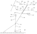
- FIG. 3 illustrates an airborne wind turbine with rotation radius that can be adapted according to the wind speed, the support structure of which is a kite, according to an embodiment of the invention.
- FIG. 4 illustrates an adaptation of the rotation radius of the blades of a wind turbine, according to an embodiment of the invention.
- FIG. 5 illustrates a boat comprising an airborne wind turbine according to an embodiment of the invention.
- FIG. 1 shows a wind turbine 10 comprising a mast as support structure 30 , two blades 20 , 21 linked by a connecting means 40 to said support structure 30 and a generator 50 fixed to each blade 20 , 21 .
- Said connecting means 40 is linked to the support structure 30 by a hub 60 and said blades 20 , 21 are able to rotate, the radius of rotation of said blades 20 , 21 being adapted according to the wind speed.
- the wind turbine is not placed into the wind but downwind, in order to avoid contact between the blades and the mast. Furthermore, the blade elements are kept in place by virtue of the centrifugal force.
- a counterweight linked to the hub 60 is placed diametrically opposite the blade 20 .
- the connecting means 40 can be a cable or else a bar in materials appropriate to the wind sector.
- the connecting means is a cable, it is essential for the blade to have a self-stabilizing profile to ensure a stability of the aerodynamic angle of incidence of the blade.
- the generators 50 can be placed anywhere on the blades 20 , 21 and preferably at blade end. Each of the generators is equipped with a propeller in order to rotate said generator.
- a winder when the connecting means 40 is a cable.
- a winder for example positioned in the hub 60 , makes it possible, by unwinding or winding the connecting means 40 , to increase or reduce the radius of rotation of the blades 20 , 21 and therefore vary the production of electricity.
- Another means of adapting the radius of rotation of the blades 20 , 21 is the use of telescopic means. That is notably feasible when the connecting means ( 40 ) is a bar.
- FIG. 2 shows an airborne wind turbine 10 linked by a cable 90 to a support structure 30 that can be raised relative to the ground by means of motors 110 , 111 and elements 115 , 116 , 120 , 121 , 122 , 123 ensuring a lift in air.
- a support structure 30 can correspond to a rotary kite 70 , said to be of helicopter type.
- kite can be used to keep the wind turbine in the air.
- the kites can be rigid or flexible, rotary or fixed. With the lift in air being assured by the kite, the wind turbine does not need to have a lift role and the blades thereof can therefore rotate in a vertical plane, in order to obtain a sweep surface area passed through by a greater mass of air and generate a better electricity yield compared to a wind turbine rotating in an oblique plane.
- kitesurf kite Such a rigid kite is the kite in rhomboid form which still graces the play of children.
- kitesurf kite An example of a flexible kite is the “kitesurf” kite which day by day gains in popularity and performance. Less known because it is more complex but no less efficient is the rotary kite. One or more blade(s) rotate about a center of rotation linked to the earth by a cable. The very large surface area swept by this type of kite ensures a lift much greater than the fixed kites with equal apparent surface area.
- Two subtypes of rotary kite can be identified, those with the rotor slightly inclined into the wind and those with the rotor strictly horizontal.
- the kite with rotor slightly inclined into the wind is nothing more than an autogiro linked to the earth by a cable.
- One very interesting example of this type of kite was used in the second world war, the Focke-Achgelis Fa 330.
- kite in fact uses the force of the wind to rotate the blades which in turn generate the lift.
- This type of kite does not require any motor to operate, but with the drawback of having a catastrophic spurious aerodynamic drag and difficulty in starting.
- the kite with strictly horizontal rotor can be likened more to the helicopter and has blade(s) which rotate in a perfectly horizontal plane.
- the latter model requires the use of motors which consume energy but has an excellent lift/drag ratio and can start on its own and land and take off vertically, an electronic control device, for example positioned in the hub or on the ground or else on the blades, can be added thereto in order to obtain a perfect stability even in the case of turbulent wind.
- kites can be used to bear the wind turbine according to the present invention.
- solutions that can be envisaged for each of these types are presented.
- the rigid or semi-rigid kite is the best known, consisting of a rigid structure (skeleton) and fabric to cover the surface.
- a kite of stabilized “airplane wing” type is also a rigid kite. It is not the form of the kite which determines its type but the manner in which it is constructed. In order to increase its lift, it will be advisable to have it sweep a large surface area by having it describe the widest possible trajectory.
- This type of kite requires the use of a long boom allowing the kite to “catch the wind” in its initial take-off phase.
- An alternative solution to the take-off boom would consist in adding a balloon (or dirigible) inflated with a gas that is lighter than air in order to permanently lift the kite in air even in the absence of wind.
- the flexible kite has become widely available through the kitesurf phenomenon; it is a kite made entirely of fabric provided with box sections which inflate by virtue of the incident wind.
- This type of kite can be seen as a paraglider sail linked to the earth via a cable.
- the take-off and landing system is fairly complicated and has already been developed by the companies Skysail (registered trademark) and Kitegen (registered trademark).
- Skysail registered trademark
- Kitegen registered trademark
- FIG. 3 A wind turbine 10 equipped with such a kite 70 according to the invention is illustrated in FIG. 3 .
- the kite of autogiro type is not a serious candidate because of the enormous aerodynamic drag that it generates and its inability to take off vertically. Only the so-called helicopter type kite will be discussed.
- the so-called helicopter type kite (with strictly horizontal rotor), as illustrated in FIG. 2 , consists of one or more rotors 115 , 116 .
- an electronic device for cyclically varying one of the aerodynamic parameters (leading angle of the blades, travel, blade-hub distance, etc.) combined with the presence of at least one sensor, must be added (as in the case of a conventional helicopter).
- a device controlling the speed of rotation of the two or more rotors (speed which will not be the same on all the rotors) is added, which causes the stability on one axis to be assured under the effect of the incident wind. On the other axis, the stability is assured by a horizontal empennage.
- the wind turbine provided with such a device then consists of a cable linking it to the ground, a central hub 60 rotating about the cable, and one or more rigid or non-rigid connecting means 40 , each connecting means being linked to a blade 20 , 21 , which is twisted or not.
- a generator 50 is mounted which is equipped with a propeller operating on startup as propulsive propeller, and then as current generator 50 .
- Such a propeller must have a strictly symmetrical profile. This generator 50 can therefore be used as motor (assisting in startup) and as current generator 50 .
- the electricity produced by the generator(s) passes through the connecting elements. the hub and the cable linked to the ground.
- said central hub 60 is equipped with a winder making it possible for the assembly to be unwound or wound in order to vary the radius of rotation of the device.
- This wind turbine 10 is itself linked by a cable 90 to a rigid structure consisting of a rigid axis 113 and possibly an empennage 114 .
- One or more rotors 115 , 116 rotate about the rigid axis 113 of the structure.
- Each of these rotors 115 , 116 is equipped with one or more rigid or non-rigid blades 120 , 121 , equipped at blade end with a wing 122 , 123 , mounted on a motor 110 , 111 with a propulsive propeller.
- the blades 120 , 121 , the wings 122 , 123 and the rotors 115 , 116 have only a lift role (kite) and do not contribute to the generation of electricity.
- the motors 110 , 111 of the kite of helicopter type are powered by the wind turbine 10 and/or the electrical network.
- Each of the rotors 115 , 116 of the kite can be equipped with a winding, unwinding device in order to vary the radius of rotation of each blade which is linked thereto.
- the wind turbine 10 is equipped with a winder situated in the hub 60 and/or on the ground, which makes it possible, in the take-off and landing phases, to accommodate and release the kite.
- the structure of the kite and that of the wind turbine will be one after the landing.
- the lift into the air will be made by virtue of the rotation of the blades of the kite. This rotation generates the lift as in the case of a conventional helicopter.
- the take-off phase is performed according to the sequencing of the following steps:
- the landing phase is performed according to the sequencing of the following steps:
- the wind turbine 10 is in a stable state aerodynamically, but it must nevertheless be attached to a device for controlling the winding and the unwinding of the cable.
- the length of the unwound cable is a function of the altitude reached, of the wind speed and of the distance which separates the wind turbine from the kite.
- An airborne wind turbine 10 that is to say when the support structure is a kite 70 , can be linked to a boat 80 thus producing the electricity powering the motor 100 propelling the boat as is illustrated in FIG. 5 . It can be linked to the boat 80 by a cable 81 .
- the point of anchorage 82 to the boat can be situated anywhere. The electricity passes through the cable 81 , the anchoring point 82 and to the motor 100 of the boat 80 .
- the winders bear a cable serving both as electrical conductor and for mechanical traction.
- No known electrical cable manufacturer offers an electrical and mechanical cable which offers all of the advantages of a good electrical conductor, small bending radius and high tensile strength.
- a winder of large diameter which is powerful and heavy for each blade
- the two winders are synchronized with one another by embedded electronics programmed for this purpose.
- the mechanical cable can consist of aramid fibers, and the electrical cable can be that used for machine tools which withstands a large number of winding windings.
- the helicopter-type kite just like the wind turbine, gains by also having an adaptive radius of rotation, therefore being equipped also with winders situated in its hub.
- Such a drone offers significant competitive advantages in terms of range, stability and lifting force.
- such an aerodynamic lift means with rotating wings offers commercial openings other than simple lifting of a wind turbine.
- the mechanical cable remains separate.
- the drag generated by the latter is negligible because it has a very small apparent diameter compared to that of the electrical cable.
- the vortex generated at wing end is a spurious eddy generated by the lift of a blade/wing; this vortex would generate an additional spurious aerodynamic drag.
- the propellers situated at blade end rotate in the reverse direction of the blade end vortex. The vortex is thus reduced. The vortex rotates from the lower surface to the upper surface of the wing, so the small secondary rotors have to rotate in the reverse direction thereof.
- the vortex generated by the blade and the eddy flow generated by the propeller represent two air flows which are undesirable and which tend to cancel each other out.
- these motors in order to ensure a maximum power/weight ratio, will advantageously be of the “in-runner” type, that is to say having permanent magnets on the rotor and not the stator.
- Such a configuration has the advantage of being more energy efficient, less expensive and more lightweight.
Landscapes
- Engineering & Computer Science (AREA)
- Mechanical Engineering (AREA)
- Life Sciences & Earth Sciences (AREA)
- Sustainable Development (AREA)
- Sustainable Energy (AREA)
- Chemical & Material Sciences (AREA)
- Combustion & Propulsion (AREA)
- General Engineering & Computer Science (AREA)
- Aviation & Aerospace Engineering (AREA)
- Physics & Mathematics (AREA)
- Fluid Mechanics (AREA)
- Wind Motors (AREA)
Abstract
Description
is the Betz limit and corresponds to me maximum theoretical efficiency, S is the surface swept by the wind turbine and V is the speed of the wind and ρ the density of the air.
-
- R is the sweep radius of the wind turbine
- B is the number of blades
- Lambda is the ratio of blade end speed to wind speed (“tip speed ratio” or tsr)
- r/R is the position on the blade of our element, at 1 it is on the end of the blade, at 0 it is at the hub level, at 0.5 it is in the middle of the blade.
and as according to the equation (1), the power is proportional to the surface area swept, therefore the generated power dP of our blade element is proportional to the position thereof on the blade.
or approximately 59%. The same applies for a wind turbine equipped with secondary rotor(s).
is nothing more than the power of the wind passing through the surface area swept by the wind turbine.
T=nρλ 2 V 2(1−α)2αS 1 (5)
(ratio between the surface area swept by a secondary rotor and the surface area swept by the blades), (4) and (5) give
P=nρ(1−α)22αλ3 V 3 S 1 (7)
in which only the solution
is physically possible.
-
- Initially, the so-called helicopter-type kite and the wind turbine with vertical rotor form a solid assembly. All the cables are completely wound and the kite occupies the top position of this assembly.
- Electricity from the network is injected into the kite, its motors set the two rotors rotating, which, by rotating, provide centrifugal force to the blades which gradually move away from the hub of their rotor. The more these blades move away from the hub, the more quickly they rotate and the more lift they produce. From a certain moment, this lift is greater than the weight of the assembly which then rises into the air.
- By rising into the air, the main cable which links the wind turbine to the ground and the cable which links the wind turbine to the kite are gradually unwound. The
kite assembly 70 then moves away from the wind turbine assembly. - On reaching a certain altitude, electricity is injected into the motors of the wind turbine which start to rotate, and by rotating, a centrifugal force is created which causes the cables of the blades to unwind from the wind turbine.
- On reaching a certain diameter which is a function of the measured wind, the unwinding of the cables of the blades of the wind turbine is blocked, and the motors of the wind turbine convert to generator mode to produce current and inject a small portion of this current into the so-called helicopter type kite and a large portion of this current into the electrical network.
-
- When the measured wind becomes too low, the generators of the wind turbine are stopped, and the winders of the wind turbine wind the cables of the blades of the wind turbine.
- Once the wind turbine is fully wound, the motors of the kite slow down and the winders wind the cables of the blades of the kite, which reduces the lift and, after a certain moment, the lift of the kite is lower than the weight of the wind turbine which causes a loss of altitude.
- By losing altitude, the cables linking the wind turbine to the ground and the wind turbine to the kite are wound. On reaching the ground, all the cables are wound and the motors/generators are stopped.
-
- Wind turbine intended for the consumer market:
- nominal power: 3 kw
- hub altitude: 40 m
- diameter of the main vertical rotor: 5 m
- number of blades: 2
- number of generators: 2 (1 installed at the end of each of the blades)
- nominal power of each of the generators: 1.5 kw
- length of a blade: 1 m
- unwound length of the cable securing each of the blades 1.5 m
- constituent material of the blade: resin/glass or carbon fiber composite
- constituent material of the cable: polyethylene of very high molar mass, copper (high performance polyethylene is situated in the middle of the cable and is used for the mechanical strength of the cable, the copper for the electrical conductivity).
- Wind turbine intended for the electricity supplier market:
- nominal power: 3 MW
- hub altitude: 250 m
- diameter of the main vertical rotor: 150 m
- number of blades: 2
- number of generators: 2 (1 installed at the end of each of the blades)
- nominal power of each of the generators: 1.5 MW
- length of a blade: 35 m
- unwound length of the cable securing each of the blades 40 m
- constituent material of the blade: resin/carbon fiber composite
- constituent material of the cable: polyethylene of very high molar mass, copper (the high performance polyethylene is situated in the middle of the cable and is used for the mechanical strength of the cable, the copper for the electrical conductivity).
- Wind turbine intended for the consumer market:
-
- 1. placing an accelerometer on the frame and a position sensor (Hall effect or optical sensor: this sensor sends a pulse, each time the blade passes in front of it), the accelerometer sends a signal that is characterized, once filtered, by an amplitude and a phase. The amplitude is proportional to the quantity of the imbalance observed. The phase indicates the position of the imbalance. This phase therefore makes it possible to determine the blade causing the imbalance.
- 2. Measuring the instantaneous current consumed by each of the motors on the winder. Since each motor has the same specification, if one of the motors consumes a greater current than the others, that indicates that the blade that it retains is pulling more than the other blades. This blade is therefore responsible for the imbalance.
Claims (19)
Applications Claiming Priority (3)
| Application Number | Priority Date | Filing Date | Title |
|---|---|---|---|
| FR1453397 | 2014-04-16 | ||
| FR1453397A FR3020096B1 (en) | 2014-04-16 | 2014-04-16 | ADAPTIVE WIND |
| PCT/EP2015/058133 WO2015158754A1 (en) | 2014-04-16 | 2015-04-15 | Adaptative wind turbine |
Publications (2)
| Publication Number | Publication Date |
|---|---|
| US20170036761A1 US20170036761A1 (en) | 2017-02-09 |
| US10864989B2 true US10864989B2 (en) | 2020-12-15 |
Family
ID=51014499
Family Applications (1)
| Application Number | Title | Priority Date | Filing Date |
|---|---|---|---|
| US15/304,220 Active 2038-02-14 US10864989B2 (en) | 2014-04-16 | 2015-04-15 | Adaptative wind turbine |
Country Status (3)
| Country | Link |
|---|---|
| US (1) | US10864989B2 (en) |
| FR (1) | FR3020096B1 (en) |
| WO (1) | WO2015158754A1 (en) |
Families Citing this family (4)
| Publication number | Priority date | Publication date | Assignee | Title |
|---|---|---|---|---|
| GB201800090D0 (en) * | 2018-01-04 | 2018-02-21 | Kiteswarms Ltd | A kite apparatus |
| EP4062052B1 (en) * | 2019-11-20 | 2024-03-13 | Bernhard Miller | High-altitude-wind turbine with autonomous wings vertical at takeoff |
| CN113306712B (en) * | 2021-05-20 | 2022-11-22 | 北斗安泽防务科技有限公司 | Unmanned aerial vehicle rotor connection structure |
| EP4428361A1 (en) * | 2023-03-07 | 2024-09-11 | Kamil PODHOLA | Wind turbine system |
Citations (23)
| Publication number | Priority date | Publication date | Assignee | Title |
|---|---|---|---|---|
| FR578074A (en) | 1923-03-13 | 1924-09-16 | Inst Voor Aero En Hydro Dynami | Flowing fluid drive machine |
| US5171127A (en) | 1988-12-23 | 1992-12-15 | Alexander Feldman | Vertical axis sail bladed wind turbine |
| WO2002086312A1 (en) | 2001-04-23 | 2002-10-31 | Forskningscenter Risø (Risø National Laboratory) | Wind turbine having secondary rotors |
| US20030230898A1 (en) | 2002-05-28 | 2003-12-18 | Jamieson Peter Mckeich | Variable diameter rotor |
| US20060093483A1 (en) * | 2002-01-18 | 2006-05-04 | Brueckner Manfred K | Sky turbine that is mounted on a city |
| US7183663B2 (en) * | 2001-11-07 | 2007-02-27 | Bryan William Roberts | Precisely controlled flying electric generators |
| US7317261B2 (en) * | 2004-02-20 | 2008-01-08 | Rolls-Royce Plc | Power generating apparatus |
| US20100032947A1 (en) * | 2008-03-06 | 2010-02-11 | Bevirt Joeben | Apparatus for generating power using jet stream wind power |
| US7675189B2 (en) * | 2007-07-17 | 2010-03-09 | Baseload Energy, Inc. | Power generation system including multiple motors/generators |
| WO2010039790A2 (en) | 2008-10-01 | 2010-04-08 | Joby Energy, Inc. | System and method for airborne cyclically controlled power generation using autorotation |
| US20100221112A1 (en) * | 2008-10-01 | 2010-09-02 | Bevirt Joeben | System and method for airborne cyclically controlled power generation using autorotation |
| US20100295320A1 (en) * | 2009-05-20 | 2010-11-25 | Bevirt Joeben | Airborne Power Generation System With Modular Electrical Elements |
| US20110121570A1 (en) * | 2009-06-19 | 2011-05-26 | Bevirt Joeben | System and method for controlling a tethered flying craft using tether attachment point manipulation |
| US20110215582A1 (en) * | 2010-03-02 | 2011-09-08 | Jorge Parera | Wind-operated electrical generating system |
| US20110260462A1 (en) * | 2010-03-24 | 2011-10-27 | Damon Vander Lind | Planform Configuration for Stability of a Powered Kite and a System and Method for Use of Same |
| US20110266809A1 (en) * | 2009-06-03 | 2011-11-03 | Grant Calverley | Gyroglider power-generation, control apparatus and method |
| US20110272527A1 (en) * | 2010-05-06 | 2011-11-10 | Larson Quinn L | Power generating kite system |
| US20120104763A1 (en) * | 2010-11-03 | 2012-05-03 | Damon Vander Lind | Kite configuration and flight strategy for flight in high wind speeds |
| US8350403B2 (en) * | 2008-07-18 | 2013-01-08 | Baseload Energy, Inc. | Tether handling for airborne electricity generators |
| EP2562084A1 (en) | 2011-08-25 | 2013-02-27 | KPS Limited | A kite for a system for extracting energy from the wind |
| US20140021723A1 (en) * | 2009-02-21 | 2014-01-23 | Frank L. Christy | Solar Tree with Optional Wind Turbine Generator |
| US20170241403A1 (en) * | 2016-02-23 | 2017-08-24 | George Auther Spencer | Vertical axis windmill |
| US20180066633A1 (en) * | 2015-10-23 | 2018-03-08 | Matteo Bojanovich | Method and means for mounting wind turbines upon a column |
-
2014
- 2014-04-16 FR FR1453397A patent/FR3020096B1/en active Active
-
2015
- 2015-04-15 US US15/304,220 patent/US10864989B2/en active Active
- 2015-04-15 WO PCT/EP2015/058133 patent/WO2015158754A1/en not_active Ceased
Patent Citations (23)
| Publication number | Priority date | Publication date | Assignee | Title |
|---|---|---|---|---|
| FR578074A (en) | 1923-03-13 | 1924-09-16 | Inst Voor Aero En Hydro Dynami | Flowing fluid drive machine |
| US5171127A (en) | 1988-12-23 | 1992-12-15 | Alexander Feldman | Vertical axis sail bladed wind turbine |
| WO2002086312A1 (en) | 2001-04-23 | 2002-10-31 | Forskningscenter Risø (Risø National Laboratory) | Wind turbine having secondary rotors |
| US7183663B2 (en) * | 2001-11-07 | 2007-02-27 | Bryan William Roberts | Precisely controlled flying electric generators |
| US20060093483A1 (en) * | 2002-01-18 | 2006-05-04 | Brueckner Manfred K | Sky turbine that is mounted on a city |
| US20030230898A1 (en) | 2002-05-28 | 2003-12-18 | Jamieson Peter Mckeich | Variable diameter rotor |
| US7317261B2 (en) * | 2004-02-20 | 2008-01-08 | Rolls-Royce Plc | Power generating apparatus |
| US7675189B2 (en) * | 2007-07-17 | 2010-03-09 | Baseload Energy, Inc. | Power generation system including multiple motors/generators |
| US20100032947A1 (en) * | 2008-03-06 | 2010-02-11 | Bevirt Joeben | Apparatus for generating power using jet stream wind power |
| US8350403B2 (en) * | 2008-07-18 | 2013-01-08 | Baseload Energy, Inc. | Tether handling for airborne electricity generators |
| US20100221112A1 (en) * | 2008-10-01 | 2010-09-02 | Bevirt Joeben | System and method for airborne cyclically controlled power generation using autorotation |
| WO2010039790A2 (en) | 2008-10-01 | 2010-04-08 | Joby Energy, Inc. | System and method for airborne cyclically controlled power generation using autorotation |
| US20140021723A1 (en) * | 2009-02-21 | 2014-01-23 | Frank L. Christy | Solar Tree with Optional Wind Turbine Generator |
| US20100295320A1 (en) * | 2009-05-20 | 2010-11-25 | Bevirt Joeben | Airborne Power Generation System With Modular Electrical Elements |
| US20110266809A1 (en) * | 2009-06-03 | 2011-11-03 | Grant Calverley | Gyroglider power-generation, control apparatus and method |
| US20110121570A1 (en) * | 2009-06-19 | 2011-05-26 | Bevirt Joeben | System and method for controlling a tethered flying craft using tether attachment point manipulation |
| US20110215582A1 (en) * | 2010-03-02 | 2011-09-08 | Jorge Parera | Wind-operated electrical generating system |
| US20110260462A1 (en) * | 2010-03-24 | 2011-10-27 | Damon Vander Lind | Planform Configuration for Stability of a Powered Kite and a System and Method for Use of Same |
| US20110272527A1 (en) * | 2010-05-06 | 2011-11-10 | Larson Quinn L | Power generating kite system |
| US20120104763A1 (en) * | 2010-11-03 | 2012-05-03 | Damon Vander Lind | Kite configuration and flight strategy for flight in high wind speeds |
| EP2562084A1 (en) | 2011-08-25 | 2013-02-27 | KPS Limited | A kite for a system for extracting energy from the wind |
| US20180066633A1 (en) * | 2015-10-23 | 2018-03-08 | Matteo Bojanovich | Method and means for mounting wind turbines upon a column |
| US20170241403A1 (en) * | 2016-02-23 | 2017-08-24 | George Auther Spencer | Vertical axis windmill |
Non-Patent Citations (1)
| Title |
|---|
| International Search Report, dated Jul. 31, 2015, from corresponding PCT Application. |
Also Published As
| Publication number | Publication date |
|---|---|
| FR3020096B1 (en) | 2019-04-19 |
| FR3020096A1 (en) | 2015-10-23 |
| WO2015158754A1 (en) | 2015-10-22 |
| US20170036761A1 (en) | 2017-02-09 |
Similar Documents
| Publication | Publication Date | Title |
|---|---|---|
| US10871149B2 (en) | Floating marine wind turbine | |
| CN105874195B (en) | Column buoy platform | |
| US9080550B2 (en) | Airborne wind energy conversion system with fast motion transfer | |
| US6616402B2 (en) | Serpentine wind turbine | |
| US7582981B1 (en) | Airborne wind turbine electricity generating system | |
| US7188808B1 (en) | Aerialwind power generation system and method | |
| US20100221112A1 (en) | System and method for airborne cyclically controlled power generation using autorotation | |
| US20110121570A1 (en) | System and method for controlling a tethered flying craft using tether attachment point manipulation | |
| US9587630B2 (en) | Rotor kite wind energy system and more | |
| US20100026007A1 (en) | Apparatus and method for harvesting wind power using tethered airfoil | |
| US20080048453A1 (en) | Tethered Wind Turbine | |
| US9732731B2 (en) | Pivoting perch for flying wind turbine parking | |
| US20110127775A1 (en) | Airborne Power Generation System With Modular Structural Elements | |
| US20210291979A1 (en) | Unmanned Aircraft, Control Method, Associated Platform and High-Altitude Turbine | |
| US9422920B2 (en) | High-altitude wind power generation system with cycloidal turbine and motor-generator, and method of operating the same | |
| US10864989B2 (en) | Adaptative wind turbine | |
| CN103403297A (en) | Horizontal axis airfoil turbine | |
| US10570886B2 (en) | Airborne device | |
| US7861973B1 (en) | Wind responsive power generation system | |
| KR20100033086A (en) | The aerial wind power generating system which uses the possibility mind levitation tube | |
| JP2018204480A (en) | Wind power generator | |
| CN221385188U (en) | Tension gain device for power kite | |
| HK1189644A (en) | Horizontal axis airfoil turbine |
Legal Events
| Date | Code | Title | Description |
|---|---|---|---|
| STPP | Information on status: patent application and granting procedure in general |
Free format text: DOCKETED NEW CASE - READY FOR EXAMINATION |
|
| STPP | Information on status: patent application and granting procedure in general |
Free format text: NON FINAL ACTION COUNTED, NOT YET MAILED |
|
| STPP | Information on status: patent application and granting procedure in general |
Free format text: NON FINAL ACTION MAILED |
|
| STPP | Information on status: patent application and granting procedure in general |
Free format text: RESPONSE TO NON-FINAL OFFICE ACTION ENTERED AND FORWARDED TO EXAMINER |
|
| STPP | Information on status: patent application and granting procedure in general |
Free format text: NON FINAL ACTION MAILED |
|
| STPP | Information on status: patent application and granting procedure in general |
Free format text: AWAITING TC RESP, ISSUE FEE PAYMENT VERIFIED |
|
| STCF | Information on status: patent grant |
Free format text: PATENTED CASE |
|
| FEPP | Fee payment procedure |
Free format text: MAINTENANCE FEE REMINDER MAILED (ORIGINAL EVENT CODE: REM.); ENTITY STATUS OF PATENT OWNER: SMALL ENTITY |
|
| FEPP | Fee payment procedure |
Free format text: SURCHARGE FOR LATE PAYMENT, SMALL ENTITY (ORIGINAL EVENT CODE: M2554); ENTITY STATUS OF PATENT OWNER: SMALL ENTITY |
|
| MAFP | Maintenance fee payment |
Free format text: PAYMENT OF MAINTENANCE FEE, 4TH YR, SMALL ENTITY (ORIGINAL EVENT CODE: M2551); ENTITY STATUS OF PATENT OWNER: SMALL ENTITY Year of fee payment: 4 |