US10864958B2 - Multi-use, three-wheel, portable, quick assemble, disassemble vehicle method thereof - Google Patents
Multi-use, three-wheel, portable, quick assemble, disassemble vehicle method thereof Download PDFInfo
- Publication number
- US10864958B2 US10864958B2 US15/872,951 US201815872951A US10864958B2 US 10864958 B2 US10864958 B2 US 10864958B2 US 201815872951 A US201815872951 A US 201815872951A US 10864958 B2 US10864958 B2 US 10864958B2
- Authority
- US
- United States
- Prior art keywords
- assembly
- coupled
- steering
- electric
- stand
- Prior art date
- Legal status (The legal status is an assumption and is not a legal conclusion. Google has not performed a legal analysis and makes no representation as to the accuracy of the status listed.)
- Active
Links
- 238000000034 method Methods 0.000 title description 10
- 230000008878 coupling Effects 0.000 claims description 53
- 238000010168 coupling process Methods 0.000 claims description 53
- 238000005859 coupling reaction Methods 0.000 claims description 53
- 230000037361 pathway Effects 0.000 claims description 7
- 230000002250 progressing effect Effects 0.000 claims 2
- 230000007246 mechanism Effects 0.000 abstract description 7
- 241000710160 Eggplant mosaic virus Species 0.000 description 59
- 230000006870 function Effects 0.000 description 7
- 239000004033 plastic Substances 0.000 description 7
- 230000008901 benefit Effects 0.000 description 6
- 230000000712 assembly Effects 0.000 description 4
- 238000000429 assembly Methods 0.000 description 4
- 230000005484 gravity Effects 0.000 description 4
- 229910052751 metal Inorganic materials 0.000 description 4
- 239000002184 metal Substances 0.000 description 4
- 230000008569 process Effects 0.000 description 4
- 230000006872 improvement Effects 0.000 description 3
- 238000002347 injection Methods 0.000 description 3
- 239000007924 injection Substances 0.000 description 3
- WHXSMMKQMYFTQS-UHFFFAOYSA-N Lithium Chemical compound [Li] WHXSMMKQMYFTQS-UHFFFAOYSA-N 0.000 description 2
- 239000002253 acid Substances 0.000 description 2
- 238000005452 bending Methods 0.000 description 2
- 239000000969 carrier Substances 0.000 description 2
- 230000007797 corrosion Effects 0.000 description 2
- 238000005260 corrosion Methods 0.000 description 2
- 230000000694 effects Effects 0.000 description 2
- 238000009434 installation Methods 0.000 description 2
- JEIPFZHSYJVQDO-UHFFFAOYSA-N iron(III) oxide Inorganic materials O=[Fe]O[Fe]=O JEIPFZHSYJVQDO-UHFFFAOYSA-N 0.000 description 2
- 229910052744 lithium Inorganic materials 0.000 description 2
- 230000008439 repair process Effects 0.000 description 2
- 208000027418 Wounds and injury Diseases 0.000 description 1
- 238000007792 addition Methods 0.000 description 1
- 230000003466 anti-cipated effect Effects 0.000 description 1
- 230000015556 catabolic process Effects 0.000 description 1
- 230000008859 change Effects 0.000 description 1
- 230000001149 cognitive effect Effects 0.000 description 1
- 230000002354 daily effect Effects 0.000 description 1
- 230000006378 damage Effects 0.000 description 1
- 201000010099 disease Diseases 0.000 description 1
- 208000037265 diseases, disorders, signs and symptoms Diseases 0.000 description 1
- 230000009977 dual effect Effects 0.000 description 1
- 230000005611 electricity Effects 0.000 description 1
- 238000005516 engineering process Methods 0.000 description 1
- 230000003203 everyday effect Effects 0.000 description 1
- 230000001771 impaired effect Effects 0.000 description 1
- 208000014674 injury Diseases 0.000 description 1
- 239000000203 mixture Substances 0.000 description 1
- 230000004048 modification Effects 0.000 description 1
- 238000012986 modification Methods 0.000 description 1
- 239000002991 molded plastic Substances 0.000 description 1
- 230000002265 prevention Effects 0.000 description 1
- 230000000135 prohibitive effect Effects 0.000 description 1
- 230000008685 targeting Effects 0.000 description 1
- 239000002699 waste material Substances 0.000 description 1
- 238000005303 weighing Methods 0.000 description 1
Images


Classifications
-
- B—PERFORMING OPERATIONS; TRANSPORTING
- B62—LAND VEHICLES FOR TRAVELLING OTHERWISE THAN ON RAILS
- B62K—CYCLES; CYCLE FRAMES; CYCLE STEERING DEVICES; RIDER-OPERATED TERMINAL CONTROLS SPECIALLY ADAPTED FOR CYCLES; CYCLE AXLE SUSPENSIONS; CYCLE SIDE-CARS, FORECARS, OR THE LIKE
- B62K5/00—Cycles with handlebars, equipped with three or more main road wheels
- B62K5/02—Tricycles
- B62K5/023—Tricycles specially adapted for disabled riders, e.g. personal mobility type vehicles with three wheels
- B62K5/025—Tricycles specially adapted for disabled riders, e.g. personal mobility type vehicles with three wheels power-driven
-
- B—PERFORMING OPERATIONS; TRANSPORTING
- B62—LAND VEHICLES FOR TRAVELLING OTHERWISE THAN ON RAILS
- B62J—CYCLE SADDLES OR SEATS; AUXILIARY DEVICES OR ACCESSORIES SPECIALLY ADAPTED TO CYCLES AND NOT OTHERWISE PROVIDED FOR, e.g. ARTICLE CARRIERS OR CYCLE PROTECTORS
- B62J43/00—Arrangements of batteries
- B62J43/10—Arrangements of batteries for propulsion
- B62J43/16—Arrangements of batteries for propulsion on motorcycles or the like
-
- B—PERFORMING OPERATIONS; TRANSPORTING
- B62—LAND VEHICLES FOR TRAVELLING OTHERWISE THAN ON RAILS
- B62J—CYCLE SADDLES OR SEATS; AUXILIARY DEVICES OR ACCESSORIES SPECIALLY ADAPTED TO CYCLES AND NOT OTHERWISE PROVIDED FOR, e.g. ARTICLE CARRIERS OR CYCLE PROTECTORS
- B62J43/00—Arrangements of batteries
- B62J43/20—Arrangements of batteries characterised by the mounting
- B62J43/28—Arrangements of batteries characterised by the mounting hidden within the cycle frame
-
- B—PERFORMING OPERATIONS; TRANSPORTING
- B62—LAND VEHICLES FOR TRAVELLING OTHERWISE THAN ON RAILS
- B62K—CYCLES; CYCLE FRAMES; CYCLE STEERING DEVICES; RIDER-OPERATED TERMINAL CONTROLS SPECIALLY ADAPTED FOR CYCLES; CYCLE AXLE SUSPENSIONS; CYCLE SIDE-CARS, FORECARS, OR THE LIKE
- B62K5/00—Cycles with handlebars, equipped with three or more main road wheels
- B62K5/02—Tricycles
- B62K5/027—Motorcycles with three wheels
-
- B—PERFORMING OPERATIONS; TRANSPORTING
- B62—LAND VEHICLES FOR TRAVELLING OTHERWISE THAN ON RAILS
- B62K—CYCLES; CYCLE FRAMES; CYCLE STEERING DEVICES; RIDER-OPERATED TERMINAL CONTROLS SPECIALLY ADAPTED FOR CYCLES; CYCLE AXLE SUSPENSIONS; CYCLE SIDE-CARS, FORECARS, OR THE LIKE
- B62K5/00—Cycles with handlebars, equipped with three or more main road wheels
- B62K5/02—Tricycles
- B62K5/06—Frames for tricycles
-
- B—PERFORMING OPERATIONS; TRANSPORTING
- B62—LAND VEHICLES FOR TRAVELLING OTHERWISE THAN ON RAILS
- B62M—RIDER PROPULSION OF WHEELED VEHICLES OR SLEDGES; POWERED PROPULSION OF SLEDGES OR SINGLE-TRACK CYCLES; TRANSMISSIONS SPECIALLY ADAPTED FOR SUCH VEHICLES
- B62M7/00—Motorcycles characterised by position of motor or engine
- B62M7/12—Motorcycles characterised by position of motor or engine with the engine beside or within the driven wheel
-
- B—PERFORMING OPERATIONS; TRANSPORTING
- B62—LAND VEHICLES FOR TRAVELLING OTHERWISE THAN ON RAILS
- B62J—CYCLE SADDLES OR SEATS; AUXILIARY DEVICES OR ACCESSORIES SPECIALLY ADAPTED TO CYCLES AND NOT OTHERWISE PROVIDED FOR, e.g. ARTICLE CARRIERS OR CYCLE PROTECTORS
- B62J43/00—Arrangements of batteries
-
- B—PERFORMING OPERATIONS; TRANSPORTING
- B62—LAND VEHICLES FOR TRAVELLING OTHERWISE THAN ON RAILS
- B62K—CYCLES; CYCLE FRAMES; CYCLE STEERING DEVICES; RIDER-OPERATED TERMINAL CONTROLS SPECIALLY ADAPTED FOR CYCLES; CYCLE AXLE SUSPENSIONS; CYCLE SIDE-CARS, FORECARS, OR THE LIKE
- B62K2204/00—Adaptations for driving cycles by electric motor
Definitions
- the present invention also includes major components designed to easily fold, collapse, or remove without the use of tools, and whereas the components are in the size and weight so as any person of modest physical strength may be capable of handling the individual components to the point where the mobility vehicle may fit into various size storage compartments or vehicles from large and small.
- this new and novel invention is aimed at resolving and addressing numerous disadvantages of the prior art presenting a stable platform that can cross the boundaries of all three of the above target groups with significant advantages and improvements so as to appeal to a majority of the users that can benefit from EMV's.
- the present invention comprises two major parts. a front major part comprising a steering assembly and a rear major part comprising a chassis.
- this invention comprises five major parts: First, a folding steering column, Second, the steering assembly, in which the folding steering column is attached, Third, the a chassis in which Fourth, a detachable seat and seat post, and Fifth, a self-contained and removable battery box are integrated to further allow this invention to rapidly break down into smaller and easier components increasing versatility by fitting in vehicles of many sizes and addressing issues for those with limited strength.
- the conical coupling assembly it is a further objective to present a newly developed double ended hand screw wherein it either secures or separates the conical coupling assembly.
- the double ended hand screw comprises a narrower threaded male end, comprising a wider threaded male end opposing the narrower threaded male end, comprising a cylindrical disc separating the opposing narrower threaded male end from the wider threaded male end, comprising a U-shaped handle pivotally mounted to the cylindrical disc.
- the double ended hand screws' wider threaded male end is screwed into the threaded hole of the downward facing female receiving end, applies downward pressure against the upper of the upward vertical facing conical male end, thus releasing and separating the conical coupling assembly.
- the U-shaped handle of the double ended hand screw pivots on bushings and acts as a lever for tightening and loosening and then lies flat on the floor deck. Additionally, the length of the U-shaped handle is in a dimension wherein should the double ended hand screw loosen during vehicle use, it makes contact with the steering assemblies rear and downward facing curved support member.
- the stand system may comprise two adjustable telescopic legs at the lower of a steering assemblies rear and downward facing curved support member, wherein the front wheel of the steering assembly and the telescopic legs form a triangular stand; or, the stand system comprises an upside down, spring tensioned, T-shaped kick stand instead of the telescopic legs.
- the horizontal bar of the T-shape kick stand provides footing on the ground when extended and then folds back under the chassis when not in use.
- Either stand system frees the user's hands to manipulate the chassis into coupling position and more importantly, while the user is standing upright rather than in a dangerous bent over stance. In addition, it relieves the user from balancing the steering assembly with one hand and while attempting to align and couple the chassis to the steering assembly with the other hand.
- a rectangular electric controller wherein the controller mounts flush to a fork of a steering assembly.
- a side of the electric controller comprises a rabbet joint wherein it mounts flush to a steering fork of a steering assembly with a respective rabbet joint.
- the seat post is removable without tools and when removed, provides extra floor space for storage or to make stowing or transport in another vehicle easier.
- a further objective of this new invention is to present a highly maneuverable vehicle that may be used indoors or outdoors, may fit through a standard size doorway, has a speed, range, and frame strength to not only function for users with walking disabilities, but functions for users who will use it for leisure, or commercial/industrial purposes.
- this invention comprises two major parts and two minor parts.
- the first major part is the front half of the EMV or the front steering assembly combined with a motor assembly comprising a steering handle mounted on a steering column.
- the steering handle comprising left and right handle grips, comprising a twist throttle with a forward and reverse button on one handle side to regulate speed and direction of the EMV by sending a signal via electrical wire to a central instrument junction box, which in turn connects to an electric controller—the electric controller which is interconnected with a battery, will send metered amounts of electricity or polarity to the motor-A steering handle comprising; a USB charge port for users to charge phones, tablets, etc.
- a central instrument junction box wherein it interconnects with an inverter and a battery comprising; a hand brake mounted on a steering handle opposite the handle of a twist throttle and connected to brakes on a motor assembly via a brake cable comprising; a horn button on the same side of the steering handle as the hand brake and electrically connected to a central instrument junction box—A central instrument junction box comprising; a box mounted on an upper of the steering column wherein the instrument comprises a key ignition, LED headlights, a horn, a display indicate if ignition is on, warning lights, and a batteries state of charge.
- the steering handle which may be telescopically adjusted, slides into the upper of a steering column folding structure and is secured in the desired height with the use of an eccentric clamp.
- the steering column folding structure comprises an eccentric clamp at the upper of the steering column folding structure to secure the handlebar height, a pivoting hinge with a locking clamp lever at the lower of the structure and is semi permanently mounted to the lower steering assembly wherein the handlebars, combined with the steering column folding structure, may fold downward.
- a folding handlebar is the first part of making an EMV easily storable or transported in a vehicle.
- a hollow, rear downward facing curved support frame member extends back and downward from the steering assembly and towards the ground comprising a pathway through the rear and downward facing curved support frame member for electrical power wires to couple an electric controller with a battery.
- Left and right steering forks extend downward from below the folding structure of the steering assembly comprising, a notched rabbet joint on a fork, comprising an electric controller with a respective rabbet joint wherein the electric controller mounts flush to a fork.
- the electric controller comprises a processor to control the EMVs functions, an electrical connector at the upper of the electric controller for connecting the wires from an instrument junction box which interconnects to a battery, an electrical connector at the lower of the electric controller, connecting a pathway to power a motor.
- the electric controller with rabbet joint coupled to a steering fork with rabbet joint is an important invention for EMVs for a number of reasons. Firstly, it simplifies the assemble and break down. It is important to note that for an EMV to truly be quick and easy to take apart, the fewer the wires and connections between a steering assembly and a chassis the better. Most of the prior art bury the electric controllers and other electrical and mechanical parts in the back half of the EMV requiring numerous parts to disconnect when breaking down the EMV into manageable sections. Most prior art that show components located on the front half, chose to use bulky and poorly engineered ways to integrate those components.
- the rabbet joint controller mounts seamlessly using what was otherwise wasted space and blends in with no unsightly boxes or mounting structures.
- the controller has a two-speed limiter button to limit top speed to 8 mph in one setting or up to 16 mph in full speed setting so users who require speed limitations have that choice.
- the electric controller to the lowest of the steering fork legs-the left and right steering forks comprise brackets to mount the respective left and right axles of the electric hub motor wheel assembly.
- a stand assembly is applied to further simplify connection of the front major part of the EMV to the back major part and comprises vertical tubes respectively mounted on the left and right lower of the curved support frame member.
- Each tube comprises a threaded horizontal hole in which a wing screw may be screwed in, to secure left and right “L” shaped telescopic legs that fit through each respective vertical tube.
- the stand assembly can be a spring tension kick stand comprising, an upside-down T shaped assembly wherein the horizontal part of the T-shape contacts the ground when extended down and folds back under the chassis when not in use.
- the telescopic stand assembly or the kick stand assembly address problems with the prior art.
- the problem with assembly and break-down of an EMV is the users' ability to easily line up the coupling components. Typically, the user must lift one section of an EMV with one hand and then lift another section with the other hand manually aligning the components to fit.
- the process can be time consuming, clumsy, and possibly an impossible feat. Additionally, the process may cause injury to users-the user may need to bend or contort into dangerous positions in order to complete the coupling.
- a stand mechanism for a steering assembly allows the user to quickly and easily stand the front major part of the invention presented here at a correct and stable height, wherein the rear major part may be effortlessly coupled to the front major part.
- the stand assembly is not used to stand the steering assembly and the user must align the front major part with the rear major part using one hand to hold the front while using the second hand to align the rear.
- the final component of the front major part is a three-part conical coupling assembly.
- the special conical coupling assembly is applied for coupling the two major parts of the invention into a complete vehicle.
- the first two parts attach to the front major part and the third part attaches to the back major part of the invention.
- the first part of the conical coupling assembly comprises a sturdy hollow beam that is horizontally attached to the lowest of the rear and downward facing curved frame support member, and with a longer of the beam facing towards the back.
- the second part comprises an upward vertical facing conical male end attached to the upper and rear of the horizontal hollow beam comprising, a vertical threaded hole machined through the center of the upward vertical facing conical male end, and wherein the lower of the upward vertical facing conical male end comprises respective left and right horizontal alignment pins.
- the upward vertical conical male end and a downward facing female receiving end have respective left and right chamfered sides in its architecture, or it can also function as a circular cone without the chamfers.
- the hollow beam provides a protected pathway for electrical wires to pass from the front major part to connect to a battery of the back major part.
- the second major part of the EMV presented here is the back of the vehicle which is the rear chassis assembly in which the user may stand or sit while driving the EMV.
- the chassis comprises a metal rectangular frame constructed of square or round tubing with three cross members.
- the first two cross members besides providing strength and rigidity, are spaced apart wherein a battery housed in removable box (minor part 1 to be discussed later) rests in a metal strap basket housing recessed under the frame, wherein the top of the removable battery box is flush with the upper of the frame.
- the second and third cross members are spaced apart to allow a seat post (minor part 2 to be discussed later) mounting bracket to be placed in the center rear of the chassis assembly comprising a rectangular plate with four threaded holes placed at the four corners of the plate and comprising a cylindrical female receiving tube in the center of the rectangular plate.
- the platform that the user stands on comprises a plastic injection molded deck coupled to the upper frame with screws and covers the frame chassis, and comprises mud guard fenders over the rear wheels, a rectangular opening over the battery box wherein the battery box may be removed, a rectangular opening to allow a seat post to be installed and removed, and a circular vertical opening at the center front of the chassis to allow for the fastening of the conical coupling assembly.
- the third part of the conical coupling assembly is part of the chassis frame and is centered and flush to the upper front of the frame comprising a downward facing female receiving end that respectively couples to the conical coupling assemblies second component (the upward vertical facing conical male end)
- the downward facing female receiving end comprises a threaded hole with a diameter equal to the diameter of the upper of the upward vertical facing conical male end.
- the user tilts the chassis back by grasping the seat with both hands, places a foot on the back of the floor deck, and pivots the rear chassis back, using the rear wheels as the pivot point-this requires no bending over and makes it much safer and easier for users who have disabilities, are older, or are frail.
- the rear chassis, without the seat installed may be coupled to the steering assembly by the user grabbing the chassis frame with one hand and maneuvering it onto the steering assembly.
- the invention presented here is designed to be simple and easy to use, tools are not required to assemble or reassemble it.
- a special double ended hand screw comprising a narrower threaded end that fits into the upper of the upward vertical facing male conical end's internal threads, securing the conical coupling assembly together comprising, a larger diameter cylindrical disc, wherein a U-shaped handle is pivotally mounted and comprises a threaded end facing the opposite direction of the narrower threaded end, with a diameter equal to the upper of the upward vertical facing conical male end.
- the U-shaped pivoting handle is used to provide leverage to secure or release the conical coupling assembly, and when not in use, pivots and lies flat on the floor deck.
- the pivoting lever also acts as a safety while lying flat wherein in the event the securing screw may loosen, the pivot lever can go no further than the point it hits the rear and downward facing curved frame support member, thus ensuring complete safety.
- the wider threaded end of the double ended hand screw with a diameter equal to the upward vertical facing conical male end, will help release and or separate the conical coupling assembly when a user screws it into the upper of the downward facing female receiving end.
- the invention presented here has been thought out so well, that anticipated issues over time are addressed making it a truly novel EMV.
- any coupled joint that is exposed to the elements may become a victim of dirt, corrosion, rust, etc.
- the conical coupling assembly couples as easy as it uncouples-unscrew the double ended hand screw, tilt the chassis back and done. But in the event the coupled conical coupling assembly becomes stuck due to lack of use, dirt, corrosion, rust etc. the user simply flips the double ended hand screw over and uses the wider threaded end to release and separate the assembly.
- the seat-post comprises a tubular post comprising an eccentric clamp at the top, a horizontal rectangular mounting plate located approximately 2 inches from the bottom of the post comprising, 4 equally spaced holes for hand screws at each corner.
- the rectangular mounting plate respectively fits over the rectangular seat post bracket in the chassis frame and the remaining 2 inches of tubular pipe slides into the receiving hole in the center of the seat post mounting bracket.
- a seat with a downward facing tubular post will fit inside the upper of the seat post and is secured with the eccentric clamp. Height of the seat may be adjusted by inserting removable pins into holes in the seat post that would correspond to holes in the downward post of the seat. In the invention presented here, the seat and seat post are easily removed.
- the seat-post may be fastened by using screws with finger grip heads, requiring no tools. Depending on how the user mounts the seat-post, it can be removed as quickly as 1 second, or with finger screws, around 15 seconds.
- the seat-post's height and location on the chassis permits the user to stand or sit comfortably without needing to remove the seat-post nor requiring bulky and complicated folding seat post mechanisms. Accordingly, in the preferred embodiment, the seat post will be installed and allows the user the flexibility and choice of whether to stand, sit, or a combination thereof and which does not limit groups of populations that the prior art with stand only or sit only EMV's focus on.
- the removable battery box comprises a plastic housing, comprising a rubber top to cover a battery, comprising two electrical connectors-one connector to supply power from a battery to Major part 1, the other connector to function as the charge port, and comprising a strap over the top of the battery box wherein the user may easily remove the battery box from the EMV with one hand.
- an additional charge port is mounted on the floor deck, then wired and connected to the charge port of the battery box. It should be noted that depending on the needs and requirements of the user, the choice of batteries placed in the battery box may vary in weight and power density. Between lithium and lead acid batteries, the battery can weigh as little as 10 lbs or as much as 38 lbs.
- FIG. 1 is a perspective of the electric mobility vehicle of the present invention.
- FIG. 4 is a perspective exploded view of the conical coupling assembly and rear and downward facing curved frame support member.
- FIG. 6 is a side view with hidden lines of the assembled conical coupling assembly and rear and downward facing curved frame support member.
- FIG. 8 is an exploded perspective view of Major part 2 (rear chassis assembly) and battery box.
- FIG. 10 is a side view of the removable seat-post with seat.
- FIG. 11 is a perspective view of the removable seat-post with seat.
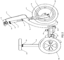
- FIG. 13 is a left side view of Major part 1 (front steering assembly).
- FIG. 16 is a side elevation of the present invention showing Major part 2 (rear chassis assembly) positioned to connect to Major part 1 (front steering assembly).
- the new and improved invention presented here is a transportable, battery powered, three wheeled electric, mobility vehicle comprising a unique coupling assembly between the two major parts of the EMV using a conical coupling assembly, a stand system, wherein the EMV may be quickly and safely assembled and disassembled into two major parts, and with the quick and easy option of breaking down the 2 nd major part into three smaller lighter parts, wherein most users may easily lift individual parts to store or transport into most locations or vehicles. More specifically:
- the steering column folding structure 7 comprises an eccentric clamp 8 at the top that allows for height adjustment of the handlebar assembly 10 , comprising a hollow tube, comprising a hinged folding mechanism 6 to allow handlebar assembly 10 to easily fold downward.
- Folding structure 7 which includes both eccentric clamp 8 and hinged folding mechanism 6 , connects to the lower steering column and steering fork 2 a and 2 b respectively.
- Moving down fork 2 a comprises a rabbet joint in the fork that mates flush, and seen more clearly in FIG. 13,14,15 , electric controller 3 with respective rabbet joints in which electric controller 3 is mounted to fork 2 a .
- Power and all corresponding handlebar wiring interconnects through wire harness 5 which runs through the rear and downward facing hollow curved frame support member 18 to the top of electric controller 3 .
- Electric controller 3 connects to the front electric hub motor 1 in which a tire 4 is mounted.
- At the lower end of fork 2 a and seen from FIG.
- electric hub motor 1 which comprise threaded axles running horizontally through it, mounts to respective left and right fork flanges with nuts.
- brake cable 11 connects to drum brake lever 25 completing the brake system.
- Attached to the lowest of the downward facing curved frame support member 18 comprises rear facing horizontal hollow beam 32 , comprising a special upward vertical facing male conical end 31 and best seen in FIG. 3,4,5,6,7 . This completes Major part 1 (front steering assembly).
- FIG. 1 generally shows the floor deck 20 which comprises and better viewed in FIG. 8,9 , a rubber floor mat 20 - 1 , injection molded plastic floor deck 20 - 2 , metal frame 33 to support the platform and house the battery box 30 , removable seat post 23 , removable/adjustable seat 22 , left wheel 24 a , right wheel 24 b , special double ended hand screw 21 .
- FIG. 3 shows an assembled side view of the special upward vertical facing conical male end wherein rear and downward facing curved frame support member 18 , horizontal hollow beam 32 , and upward vertical facing conical male end 31 are all combined and lined up to accept the downward facing female receiving end 28 , to which special double ended hand screw 21 will complete the assembly.
- FIG. 4 respectively shows a perspective view of FIG. 3 which shows more of the special conical coupling assemblies' architecture.
- FIG. 7 depicts Major part 1 (front steering assembly) freely standing upright using the special telescopic stand system.
- telescopic L-shaped legs 19 a and 19 b are in the upright position and the feet of the L-shaped legs are positioned to face the rear of the EMV, out of the way and secured tightly by respective wing screws 27 a , 27 b .
- FIG. 8 perspective and FIG. 9 right side views respectively illustrate exploded and layered views of Major part 2 (rear chassis assembly) and for further clarity, minus seat post 23 , seat 22 , right wheel 24 b , right fender of plastic floor deck 20 - 2 , and the rear axle.
- the layers comprise a rubber floor mat 20 - 1 with openings to allow special double ended hand screw 21 and seat post 23 to pass through, a plastic injection molded floor deck 20 - 2 with respective openings to allow special double ended hand screw 21 , battery box 30 , and seat post 23 to pass through.
- the removable seat and seat-post adds to the versatility of the invention presented here.
- the preferred embodiment will include seat post 23 and seat 22 .
- seat-post 23 and seat 22 may be additionally secured with hand screws, requiring no tools to screw in or out and would typically be applied when the user is not planning on removing seat-post 23 and seat 22 very often.
- FIG. 12 removable battery comprises plastic battery box 30 , comprising electrical connectors 35 a and 35 b whereas 35b is a charge port and whereas 35a is the power connector to which a wire from Major part 1(front steering assembly) will interconnect the battery to the electric controller, comprising a durable rubber top 36 to cover the battery, comprising strap 37 for lifting the battery box 30 in and out of deck frame 33 .
- the battery housed in the battery box 30 (Minor part 1) which, depending on the type of battery, ie. Lithium or sealed lead acid, may weigh as Little as 10 lbs or up to 38 lbs provides a driving range of up to 30 miles.
- an easily removable battery box 30 allows the user to charge the battery away from the EMV which benefits not only individual users, but to rental, and industrial users who may want to have spare charged battery packs ready to swap out when the current battery is exhausted, thus reducing down time and increasing efficiency.
- FIG. 13, 14,15 show left side, rear, and perspective views respectively and focus on electric controller with rabbet joint 3 coupling with left fork 2 a 's respective rabbet joint.
- Detail A of FIG. 14 shows an enlarged view with hidden lines clarifying how neatly electric controller with rabbet joint 3 couples to fork 2 a . Though it may seem trivial, this is important for a number of reasons:
- FIG. 16 shows in the preferred embodiment, Major part 2 in a tilted back position and lined up to connect with Major part 1 and in which the telescopic stand system is applied, allowing Major part 1 to stand freely at the perfect height to easily couple downward facing female receiving end 28 onto upward vertical facing male conical end 31 .
- the user grasps seat 22 with his/her hands, and while one foot is positioned on the rear of floor deck 20 , tilts Major part 2 (rear chassis assembly) back, aligns with Major part 1 (front steering assembly) and lowers, thus coupling Major part 2 with Major part 1 and forming a complete vehicle once electrically connecting battery box 30 to electric controller with rabbet joint 3 .
- the user aligns Major part 2 with Major part 1 by bending down and simply lifting the front of Major part 2 with one hand and setting it on Major part 1.
Landscapes
- Engineering & Computer Science (AREA)
- Mechanical Engineering (AREA)
- Chemical & Material Sciences (AREA)
- Combustion & Propulsion (AREA)
- Transportation (AREA)
- Motorcycle And Bicycle Frame (AREA)
Abstract
Description
- 1. This allows the floor deck to be flat-a flat floor deck is key to targeting the 3 populations discussed here:
- (A) First, persons with walking disabilities often have pain and trouble lifting their legs. Many EMV's have batteries mounted on top of the floor decks which require the user to lift his/her legs over the battery when mounting or dismounting the vehicle. In addition, there is less room for the user's feet to be comfortably placed.
- (B) Second, persons who will use the EMV presented here as a form of recreation also Benefit from the flat floor deck because like persons with disabilities, they find that the extra space is more comfortable plus it is more streamline not having a bulky battery in view.
- (C) Third, industrial users-along with users that have walking disabilities and recreational users, the added real estate that a flat deck provides allows users to place boxes and other forms of cargo, or even an additional passenger on the deck (especially with the seat post removed) and can move their cargo quickly and efficiently.
- 2. Second, the batteries' low center of gravity provides extra stability which translates to a better ride and better safety from tipping.
- 1. For a quick assembly or disassembly system to be efficient,
Major part 1 andMajor part 2 must have very few connections between each other. Electric controller with rabbet joint 3 mounted onMajor part 1 leaves only a single wire to connect or disconnect when assembling or disassemblingMajor part 1 to and fromMajor part 2. - 2. Because electric controller with rabbet joint 3 is mounted close to the motor and close to the wiring harness, there is less chance for damaging wires and less wiring heat up during operation.
- 3. Diagnostic, repair, and replacement is much easier with electric controller with rabbet joint 3 mounted externally.
- 4. Because it is almost invisible, taking up no room on the handlebars nor steering column, the flush mounted electric controller with rabbet joint 3 coupled to fork 2 a is an improvement that will provide a greater chance for commercial success in all populations targeted.
Claims (5)
Priority Applications (1)
| Application Number | Priority Date | Filing Date | Title |
|---|---|---|---|
| US15/872,951 US10864958B2 (en) | 2018-01-16 | 2018-01-16 | Multi-use, three-wheel, portable, quick assemble, disassemble vehicle method thereof |
Applications Claiming Priority (1)
| Application Number | Priority Date | Filing Date | Title |
|---|---|---|---|
| US15/872,951 US10864958B2 (en) | 2018-01-16 | 2018-01-16 | Multi-use, three-wheel, portable, quick assemble, disassemble vehicle method thereof |
Publications (2)
| Publication Number | Publication Date |
|---|---|
| US20190217912A1 US20190217912A1 (en) | 2019-07-18 |
| US10864958B2 true US10864958B2 (en) | 2020-12-15 |
Family
ID=67213249
Family Applications (1)
| Application Number | Title | Priority Date | Filing Date |
|---|---|---|---|
| US15/872,951 Active US10864958B2 (en) | 2018-01-16 | 2018-01-16 | Multi-use, three-wheel, portable, quick assemble, disassemble vehicle method thereof |
Country Status (1)
| Country | Link |
|---|---|
| US (1) | US10864958B2 (en) |
Cited By (3)
| Publication number | Priority date | Publication date | Assignee | Title |
|---|---|---|---|---|
| USD934956S1 (en) | 2021-05-23 | 2021-11-02 | Raymond Rhamey | Folding electric personal utility scooter |
| US20240166293A1 (en) * | 2022-11-17 | 2024-05-23 | Polaris Industries Inc. | Utility vehicle |
| USD1092293S1 (en) * | 2023-05-18 | 2025-09-09 | Jeffrey Schneider | Electric scooter |
Families Citing this family (5)
| Publication number | Priority date | Publication date | Assignee | Title |
|---|---|---|---|---|
| US10988032B2 (en) | 2016-04-19 | 2021-04-27 | Walnut Technology Limited | Self-propelled personal transportation device |
| CN108786083B (en) * | 2017-04-28 | 2020-05-05 | 胡桃智能科技(东莞)有限公司 | Electric vehicle, electric vehicle system and control method thereof |
| US11260926B2 (en) * | 2018-01-24 | 2022-03-01 | Jeffrey Schneider | Folding portable electric scooter |
| US11225167B2 (en) * | 2018-10-02 | 2022-01-18 | Assembled Products Corporation | Electric cart |
| USD1105990S1 (en) * | 2024-11-28 | 2025-12-16 | Shenzhen Hatcher Intelligent Technology Co., Ltd. | Electric tricycle |
Citations (16)
| Publication number | Priority date | Publication date | Assignee | Title |
|---|---|---|---|---|
| US3605929A (en) * | 1969-07-07 | 1971-09-20 | Burton A Rolland | One rider golf cart |
| US4909525A (en) * | 1989-01-13 | 1990-03-20 | Michael Flowers | Convertible personal vehicle having a take-apart frame |
| US5020624A (en) * | 1989-11-13 | 1991-06-04 | Everest & Jennings, Inc. | Power drive scooter |
| US5036938A (en) * | 1989-03-13 | 1991-08-06 | Blount Wendell G | Disassemblable riding scooter |
| US5064209A (en) * | 1990-12-03 | 1991-11-12 | Kurschat Erich G | Combined trailer/wheelchair |
| US5090513A (en) * | 1990-12-24 | 1992-02-25 | Amigo Mobility International, Inc. | Powered wheeled vehicle for the handicapped and others desiring assistance incorporating automatically locking swivelable and raiseable powered seat |
| US5228533A (en) * | 1990-12-27 | 1993-07-20 | Genus Medical Inc. | Knockdown motorized scooter |
| US5848660A (en) * | 1997-04-16 | 1998-12-15 | Zap Power Systems | Portable collapsible scooter |
| US6170592B1 (en) * | 1999-06-09 | 2001-01-09 | Donald P. H. Wu | Detachable framework for an electric cart |
| US6176337B1 (en) * | 1997-04-30 | 2001-01-23 | Golden Technologies, Inc. | Personal mobility vehicle |
| US6378642B1 (en) * | 2001-02-26 | 2002-04-30 | Eugene R Sutton | Motorized scooter |
| US7044249B2 (en) * | 2003-12-30 | 2006-05-16 | Ju-Yu Fan | Connecting structure of front and rear frame parts of a cart for people to ride on |
| US7234557B2 (en) * | 2004-10-26 | 2007-06-26 | Yung Cheng Chen | Electric vehicle with partitionable structure |
| US7363998B2 (en) * | 2005-12-07 | 2008-04-29 | Ju-Yu Fan | Walk-substituting cart chassis structure |
| US9174692B2 (en) * | 2012-10-02 | 2015-11-03 | Acton, Inc. | Foldable mobility device |
| US20190225294A1 (en) * | 2018-01-24 | 2019-07-25 | Jeffrey Schneider | Folding portable electric scooter |
-
2018
- 2018-01-16 US US15/872,951 patent/US10864958B2/en active Active
Patent Citations (16)
| Publication number | Priority date | Publication date | Assignee | Title |
|---|---|---|---|---|
| US3605929A (en) * | 1969-07-07 | 1971-09-20 | Burton A Rolland | One rider golf cart |
| US4909525A (en) * | 1989-01-13 | 1990-03-20 | Michael Flowers | Convertible personal vehicle having a take-apart frame |
| US5036938A (en) * | 1989-03-13 | 1991-08-06 | Blount Wendell G | Disassemblable riding scooter |
| US5020624A (en) * | 1989-11-13 | 1991-06-04 | Everest & Jennings, Inc. | Power drive scooter |
| US5064209A (en) * | 1990-12-03 | 1991-11-12 | Kurschat Erich G | Combined trailer/wheelchair |
| US5090513A (en) * | 1990-12-24 | 1992-02-25 | Amigo Mobility International, Inc. | Powered wheeled vehicle for the handicapped and others desiring assistance incorporating automatically locking swivelable and raiseable powered seat |
| US5228533A (en) * | 1990-12-27 | 1993-07-20 | Genus Medical Inc. | Knockdown motorized scooter |
| US5848660A (en) * | 1997-04-16 | 1998-12-15 | Zap Power Systems | Portable collapsible scooter |
| US6176337B1 (en) * | 1997-04-30 | 2001-01-23 | Golden Technologies, Inc. | Personal mobility vehicle |
| US6170592B1 (en) * | 1999-06-09 | 2001-01-09 | Donald P. H. Wu | Detachable framework for an electric cart |
| US6378642B1 (en) * | 2001-02-26 | 2002-04-30 | Eugene R Sutton | Motorized scooter |
| US7044249B2 (en) * | 2003-12-30 | 2006-05-16 | Ju-Yu Fan | Connecting structure of front and rear frame parts of a cart for people to ride on |
| US7234557B2 (en) * | 2004-10-26 | 2007-06-26 | Yung Cheng Chen | Electric vehicle with partitionable structure |
| US7363998B2 (en) * | 2005-12-07 | 2008-04-29 | Ju-Yu Fan | Walk-substituting cart chassis structure |
| US9174692B2 (en) * | 2012-10-02 | 2015-11-03 | Acton, Inc. | Foldable mobility device |
| US20190225294A1 (en) * | 2018-01-24 | 2019-07-25 | Jeffrey Schneider | Folding portable electric scooter |
Cited By (3)
| Publication number | Priority date | Publication date | Assignee | Title |
|---|---|---|---|---|
| USD934956S1 (en) | 2021-05-23 | 2021-11-02 | Raymond Rhamey | Folding electric personal utility scooter |
| US20240166293A1 (en) * | 2022-11-17 | 2024-05-23 | Polaris Industries Inc. | Utility vehicle |
| USD1092293S1 (en) * | 2023-05-18 | 2025-09-09 | Jeffrey Schneider | Electric scooter |
Also Published As
| Publication number | Publication date |
|---|---|
| US20190217912A1 (en) | 2019-07-18 |
Similar Documents
| Publication | Publication Date | Title |
|---|---|---|
| US10864958B2 (en) | Multi-use, three-wheel, portable, quick assemble, disassemble vehicle method thereof | |
| US11260926B2 (en) | Folding portable electric scooter | |
| US11535330B2 (en) | Folding bicycle and method of use | |
| US7293619B2 (en) | Front wheel motor driven-golf trolley | |
| US8585071B2 (en) | Releasable forward wheel apparatus for a wheelchair | |
| US9744095B1 (en) | Self-propelled walker | |
| US4094374A (en) | Two wheeled electrically powered vehicle | |
| US9757290B1 (en) | Adjustable device for attaching a manual wheelchair to a scooter | |
| US10675206B2 (en) | Electrically driven wheeled walker | |
| US9731785B1 (en) | Tiltable electric tricycle | |
| US3934669A (en) | Powered vehicle | |
| US7461715B1 (en) | Personal mobility vehicle with releasable folding seat | |
| JPH0374578B2 (en) | ||
| US5927730A (en) | Scooter cart | |
| CN110785343B (en) | System for Rolling and Folding Bicycles | |
| US9988114B1 (en) | Self-balancing stand-up transporter-driven trailer | |
| CN108243606A (en) | Attachments for wheelchairs | |
| US7207407B2 (en) | Quick disconnect support bracket for a wheeled vehicle | |
| WO2004028890A1 (en) | Folding bicycle | |
| WO2004093595A1 (en) | Trolley type contaiiner, convertible into a scooter | |
| US6896079B1 (en) | Convertible wheelchair and methods for making the same | |
| CN107472431A (en) | Segway Human Transporter | |
| GB2282355A (en) | Motorised personal transport vehicle | |
| GB2563083A (en) | Rear attendant standing platform for a manual or self propelled wheelchair adapted with a battery powered propulsion system | |
| RU2735878C1 (en) | Light trolley for transportation of goods and passengers over rough terrain |
Legal Events
| Date | Code | Title | Description |
|---|---|---|---|
| FEPP | Fee payment procedure |
Free format text: ENTITY STATUS SET TO UNDISCOUNTED (ORIGINAL EVENT CODE: BIG.); ENTITY STATUS OF PATENT OWNER: MICROENTITY |
|
| FEPP | Fee payment procedure |
Free format text: ENTITY STATUS SET TO MICRO (ORIGINAL EVENT CODE: MICR); ENTITY STATUS OF PATENT OWNER: MICROENTITY |
|
| STPP | Information on status: patent application and granting procedure in general |
Free format text: NON FINAL ACTION MAILED |
|
| STPP | Information on status: patent application and granting procedure in general |
Free format text: NON FINAL ACTION MAILED |
|
| STPP | Information on status: patent application and granting procedure in general |
Free format text: NON FINAL ACTION MAILED |
|
| STPP | Information on status: patent application and granting procedure in general |
Free format text: RESPONSE TO NON-FINAL OFFICE ACTION ENTERED AND FORWARDED TO EXAMINER |
|
| STPP | Information on status: patent application and granting procedure in general |
Free format text: FINAL REJECTION MAILED |
|
| STPP | Information on status: patent application and granting procedure in general |
Free format text: RESPONSE AFTER FINAL ACTION FORWARDED TO EXAMINER |
|
| STPP | Information on status: patent application and granting procedure in general |
Free format text: PUBLICATIONS -- ISSUE FEE PAYMENT RECEIVED |
|
| STPP | Information on status: patent application and granting procedure in general |
Free format text: PUBLICATIONS -- ISSUE FEE PAYMENT VERIFIED |
|
| STCF | Information on status: patent grant |
Free format text: PATENTED CASE |
|
| MAFP | Maintenance fee payment |
Free format text: PAYMENT OF MAINTENANCE FEE, 4TH YEAR, MICRO ENTITY (ORIGINAL EVENT CODE: M3551); ENTITY STATUS OF PATENT OWNER: MICROENTITY Year of fee payment: 4 |