US10864946B2 - Automotive panel structure - Google Patents
Automotive panel structure Download PDFInfo
- Publication number
- US10864946B2 US10864946B2 US16/170,837 US201816170837A US10864946B2 US 10864946 B2 US10864946 B2 US 10864946B2 US 201816170837 A US201816170837 A US 201816170837A US 10864946 B2 US10864946 B2 US 10864946B2
- Authority
- US
- United States
- Prior art keywords
- wall
- panel
- wall panel
- double
- hollow double
- Prior art date
- Legal status (The legal status is an assumption and is not a legal conclusion. Google has not performed a legal analysis and makes no representation as to the accuracy of the status listed.)
- Active, expires
Links
- 239000011162 core material Substances 0.000 claims abstract description 140
- 239000012792 core layer Substances 0.000 claims description 101
- 230000013011 mating Effects 0.000 claims description 81
- 239000000463 material Substances 0.000 claims description 72
- 239000000835 fiber Substances 0.000 claims description 62
- 230000002093 peripheral effect Effects 0.000 claims description 51
- 239000000126 substance Substances 0.000 claims description 47
- 238000012856 packing Methods 0.000 claims description 26
- 229920005989 resin Polymers 0.000 claims description 18
- 239000011347 resin Substances 0.000 claims description 18
- 239000006260 foam Substances 0.000 claims description 13
- 239000003566 sealing material Substances 0.000 claims description 12
- 239000011521 glass Substances 0.000 claims description 7
- 239000004743 Polypropylene Substances 0.000 claims description 5
- 229920000728 polyester Polymers 0.000 claims description 5
- -1 polypropylene Polymers 0.000 claims description 4
- 229920001155 polypropylene Polymers 0.000 claims description 4
- 229920000178 Acrylic resin Polymers 0.000 claims description 3
- 239000004925 Acrylic resin Substances 0.000 claims description 3
- 229920000742 Cotton Polymers 0.000 claims description 3
- 239000004677 Nylon Substances 0.000 claims description 3
- 229920000297 Rayon Polymers 0.000 claims description 3
- 229920001971 elastomer Polymers 0.000 claims description 3
- 229920001778 nylon Polymers 0.000 claims description 3
- 229920002635 polyurethane Polymers 0.000 claims description 3
- 239000004814 polyurethane Substances 0.000 claims description 3
- 239000002964 rayon Substances 0.000 claims description 3
- 239000005060 rubber Substances 0.000 claims description 3
- 230000000149 penetrating effect Effects 0.000 claims description 2
- 230000005540 biological transmission Effects 0.000 abstract description 49
- 239000007789 gas Substances 0.000 description 60
- 238000010586 diagram Methods 0.000 description 26
- 239000000853 adhesive Substances 0.000 description 23
- 230000001070 adhesive effect Effects 0.000 description 23
- 230000003247 decreasing effect Effects 0.000 description 20
- 238000009413 insulation Methods 0.000 description 19
- 238000013016 damping Methods 0.000 description 18
- 239000010410 layer Substances 0.000 description 18
- 238000010521 absorption reaction Methods 0.000 description 15
- 230000007423 decrease Effects 0.000 description 14
- XEEYBQQBJWHFJM-UHFFFAOYSA-N Iron Chemical compound [Fe] XEEYBQQBJWHFJM-UHFFFAOYSA-N 0.000 description 12
- 230000006835 compression Effects 0.000 description 12
- 238000007906 compression Methods 0.000 description 12
- 230000000694 effects Effects 0.000 description 10
- 229910018503 SF6 Inorganic materials 0.000 description 8
- 229910000831 Steel Inorganic materials 0.000 description 7
- 238000005452 bending Methods 0.000 description 7
- 239000010959 steel Substances 0.000 description 7
- 229910052782 aluminium Inorganic materials 0.000 description 6
- XAGFODPZIPBFFR-UHFFFAOYSA-N aluminium Chemical compound [Al] XAGFODPZIPBFFR-UHFFFAOYSA-N 0.000 description 6
- 229910052742 iron Inorganic materials 0.000 description 6
- 238000012423 maintenance Methods 0.000 description 6
- 230000004048 modification Effects 0.000 description 6
- 238000012986 modification Methods 0.000 description 6
- SFZCNBIFKDRMGX-UHFFFAOYSA-N sulfur hexafluoride Chemical compound FS(F)(F)(F)(F)F SFZCNBIFKDRMGX-UHFFFAOYSA-N 0.000 description 5
- 229960000909 sulfur hexafluoride Drugs 0.000 description 5
- 238000004873 anchoring Methods 0.000 description 4
- 238000000071 blow moulding Methods 0.000 description 4
- 230000006872 improvement Effects 0.000 description 4
- 238000005304 joining Methods 0.000 description 4
- 238000004519 manufacturing process Methods 0.000 description 4
- 230000007246 mechanism Effects 0.000 description 4
- 238000000034 method Methods 0.000 description 4
- 230000009467 reduction Effects 0.000 description 4
- 229920005992 thermoplastic resin Polymers 0.000 description 4
- 229920001187 thermosetting polymer Polymers 0.000 description 4
- FYYHWMGAXLPEAU-UHFFFAOYSA-N Magnesium Chemical compound [Mg] FYYHWMGAXLPEAU-UHFFFAOYSA-N 0.000 description 3
- 230000008859 change Effects 0.000 description 3
- WRQGPGZATPOHHX-UHFFFAOYSA-N ethyl 2-oxohexanoate Chemical compound CCCCC(=O)C(=O)OCC WRQGPGZATPOHHX-UHFFFAOYSA-N 0.000 description 3
- 229910052749 magnesium Inorganic materials 0.000 description 3
- 239000011777 magnesium Substances 0.000 description 3
- 229910052751 metal Inorganic materials 0.000 description 3
- 239000002184 metal Substances 0.000 description 3
- 239000012071 phase Substances 0.000 description 3
- OHMHBGPWCHTMQE-UHFFFAOYSA-N 2,2-dichloro-1,1,1-trifluoroethane Chemical compound FC(F)(F)C(Cl)Cl OHMHBGPWCHTMQE-UHFFFAOYSA-N 0.000 description 2
- 230000000052 comparative effect Effects 0.000 description 2
- 239000002828 fuel tank Substances 0.000 description 2
- 239000002245 particle Substances 0.000 description 2
- 239000011343 solid material Substances 0.000 description 2
- 238000003466 welding Methods 0.000 description 2
- JOYRKODLDBILNP-UHFFFAOYSA-N Ethyl urethane Chemical compound CCOC(N)=O JOYRKODLDBILNP-UHFFFAOYSA-N 0.000 description 1
- 238000013459 approach Methods 0.000 description 1
- 230000008901 benefit Effects 0.000 description 1
- 238000006243 chemical reaction Methods 0.000 description 1
- 238000006073 displacement reaction Methods 0.000 description 1
- 238000003780 insertion Methods 0.000 description 1
- 230000037431 insertion Effects 0.000 description 1
- 229910052743 krypton Inorganic materials 0.000 description 1
- DNNSSWSSYDEUBZ-UHFFFAOYSA-N krypton atom Chemical compound [Kr] DNNSSWSSYDEUBZ-UHFFFAOYSA-N 0.000 description 1
- 238000005192 partition Methods 0.000 description 1
- 230000035699 permeability Effects 0.000 description 1
- 229920001225 polyester resin Polymers 0.000 description 1
- 239000004645 polyester resin Substances 0.000 description 1
- 238000003825 pressing Methods 0.000 description 1
- 230000008569 process Effects 0.000 description 1
- 230000002787 reinforcement Effects 0.000 description 1
- 239000007787 solid Substances 0.000 description 1
- 239000007790 solid phase Substances 0.000 description 1
- 229920003051 synthetic elastomer Polymers 0.000 description 1
- 229920002994 synthetic fiber Polymers 0.000 description 1
- 239000012209 synthetic fiber Substances 0.000 description 1
- 239000005061 synthetic rubber Substances 0.000 description 1
- 229910052724 xenon Inorganic materials 0.000 description 1
- FHNFHKCVQCLJFQ-UHFFFAOYSA-N xenon atom Chemical compound [Xe] FHNFHKCVQCLJFQ-UHFFFAOYSA-N 0.000 description 1
Images


Classifications
-
- B—PERFORMING OPERATIONS; TRANSPORTING
- B32—LAYERED PRODUCTS
- B32B—LAYERED PRODUCTS, i.e. PRODUCTS BUILT-UP OF STRATA OF FLAT OR NON-FLAT, e.g. CELLULAR OR HONEYCOMB, FORM
- B32B3/00—Layered products comprising a layer with external or internal discontinuities or unevennesses, or a layer of non-planar shape; Layered products comprising a layer having particular features of form
- B32B3/26—Layered products comprising a layer with external or internal discontinuities or unevennesses, or a layer of non-planar shape; Layered products comprising a layer having particular features of form characterised by a particular shape of the outline of the cross-section of a continuous layer; characterised by a layer with cavities or internal voids ; characterised by an apertured layer
- B32B3/266—Layered products comprising a layer with external or internal discontinuities or unevennesses, or a layer of non-planar shape; Layered products comprising a layer having particular features of form characterised by a particular shape of the outline of the cross-section of a continuous layer; characterised by a layer with cavities or internal voids ; characterised by an apertured layer characterised by an apertured layer, the apertures going through the whole thickness of the layer, e.g. expanded metal, perforated layer, slit layer regular cells B32B3/12
-
- B—PERFORMING OPERATIONS; TRANSPORTING
- B62—LAND VEHICLES FOR TRAVELLING OTHERWISE THAN ON RAILS
- B62D—MOTOR VEHICLES; TRAILERS
- B62D25/00—Superstructure or monocoque structure sub-units; Parts or details thereof not otherwise provided for
- B62D25/02—Side panels
-
- B—PERFORMING OPERATIONS; TRANSPORTING
- B32—LAYERED PRODUCTS
- B32B—LAYERED PRODUCTS, i.e. PRODUCTS BUILT-UP OF STRATA OF FLAT OR NON-FLAT, e.g. CELLULAR OR HONEYCOMB, FORM
- B32B15/00—Layered products comprising a layer of metal
- B32B15/04—Layered products comprising a layer of metal comprising metal as the main or only constituent of a layer, which is next to another layer of the same or of a different material
- B32B15/043—Layered products comprising a layer of metal comprising metal as the main or only constituent of a layer, which is next to another layer of the same or of a different material of metal
-
- B—PERFORMING OPERATIONS; TRANSPORTING
- B32—LAYERED PRODUCTS
- B32B—LAYERED PRODUCTS, i.e. PRODUCTS BUILT-UP OF STRATA OF FLAT OR NON-FLAT, e.g. CELLULAR OR HONEYCOMB, FORM
- B32B15/00—Layered products comprising a layer of metal
- B32B15/04—Layered products comprising a layer of metal comprising metal as the main or only constituent of a layer, which is next to another layer of the same or of a different material
- B32B15/08—Layered products comprising a layer of metal comprising metal as the main or only constituent of a layer, which is next to another layer of the same or of a different material of synthetic resin
-
- B—PERFORMING OPERATIONS; TRANSPORTING
- B32—LAYERED PRODUCTS
- B32B—LAYERED PRODUCTS, i.e. PRODUCTS BUILT-UP OF STRATA OF FLAT OR NON-FLAT, e.g. CELLULAR OR HONEYCOMB, FORM
- B32B15/00—Layered products comprising a layer of metal
- B32B15/14—Layered products comprising a layer of metal next to a fibrous or filamentary layer
-
- B—PERFORMING OPERATIONS; TRANSPORTING
- B32—LAYERED PRODUCTS
- B32B—LAYERED PRODUCTS, i.e. PRODUCTS BUILT-UP OF STRATA OF FLAT OR NON-FLAT, e.g. CELLULAR OR HONEYCOMB, FORM
- B32B15/00—Layered products comprising a layer of metal
- B32B15/18—Layered products comprising a layer of metal comprising iron or steel
-
- B—PERFORMING OPERATIONS; TRANSPORTING
- B32—LAYERED PRODUCTS
- B32B—LAYERED PRODUCTS, i.e. PRODUCTS BUILT-UP OF STRATA OF FLAT OR NON-FLAT, e.g. CELLULAR OR HONEYCOMB, FORM
- B32B15/00—Layered products comprising a layer of metal
- B32B15/20—Layered products comprising a layer of metal comprising aluminium or copper
-
- B—PERFORMING OPERATIONS; TRANSPORTING
- B32—LAYERED PRODUCTS
- B32B—LAYERED PRODUCTS, i.e. PRODUCTS BUILT-UP OF STRATA OF FLAT OR NON-FLAT, e.g. CELLULAR OR HONEYCOMB, FORM
- B32B25/00—Layered products comprising a layer of natural or synthetic rubber
- B32B25/04—Layered products comprising a layer of natural or synthetic rubber comprising rubber as the main or only constituent of a layer, which is next to another layer of the same or of a different material
- B32B25/045—Layered products comprising a layer of natural or synthetic rubber comprising rubber as the main or only constituent of a layer, which is next to another layer of the same or of a different material of foam
-
- B—PERFORMING OPERATIONS; TRANSPORTING
- B32—LAYERED PRODUCTS
- B32B—LAYERED PRODUCTS, i.e. PRODUCTS BUILT-UP OF STRATA OF FLAT OR NON-FLAT, e.g. CELLULAR OR HONEYCOMB, FORM
- B32B25/00—Layered products comprising a layer of natural or synthetic rubber
- B32B25/10—Layered products comprising a layer of natural or synthetic rubber next to a fibrous or filamentary layer
-
- B—PERFORMING OPERATIONS; TRANSPORTING
- B32—LAYERED PRODUCTS
- B32B—LAYERED PRODUCTS, i.e. PRODUCTS BUILT-UP OF STRATA OF FLAT OR NON-FLAT, e.g. CELLULAR OR HONEYCOMB, FORM
- B32B27/00—Layered products comprising a layer of synthetic resin
- B32B27/06—Layered products comprising a layer of synthetic resin as the main or only constituent of a layer, which is next to another layer of the same or of a different material
- B32B27/065—Layered products comprising a layer of synthetic resin as the main or only constituent of a layer, which is next to another layer of the same or of a different material of foam
-
- B—PERFORMING OPERATIONS; TRANSPORTING
- B32—LAYERED PRODUCTS
- B32B—LAYERED PRODUCTS, i.e. PRODUCTS BUILT-UP OF STRATA OF FLAT OR NON-FLAT, e.g. CELLULAR OR HONEYCOMB, FORM
- B32B27/00—Layered products comprising a layer of synthetic resin
- B32B27/06—Layered products comprising a layer of synthetic resin as the main or only constituent of a layer, which is next to another layer of the same or of a different material
- B32B27/08—Layered products comprising a layer of synthetic resin as the main or only constituent of a layer, which is next to another layer of the same or of a different material of synthetic resin
-
- B—PERFORMING OPERATIONS; TRANSPORTING
- B32—LAYERED PRODUCTS
- B32B—LAYERED PRODUCTS, i.e. PRODUCTS BUILT-UP OF STRATA OF FLAT OR NON-FLAT, e.g. CELLULAR OR HONEYCOMB, FORM
- B32B27/00—Layered products comprising a layer of synthetic resin
- B32B27/12—Layered products comprising a layer of synthetic resin next to a fibrous or filamentary layer
-
- B—PERFORMING OPERATIONS; TRANSPORTING
- B32—LAYERED PRODUCTS
- B32B—LAYERED PRODUCTS, i.e. PRODUCTS BUILT-UP OF STRATA OF FLAT OR NON-FLAT, e.g. CELLULAR OR HONEYCOMB, FORM
- B32B27/00—Layered products comprising a layer of synthetic resin
- B32B27/32—Layered products comprising a layer of synthetic resin comprising polyolefins
-
- B—PERFORMING OPERATIONS; TRANSPORTING
- B32—LAYERED PRODUCTS
- B32B—LAYERED PRODUCTS, i.e. PRODUCTS BUILT-UP OF STRATA OF FLAT OR NON-FLAT, e.g. CELLULAR OR HONEYCOMB, FORM
- B32B27/00—Layered products comprising a layer of synthetic resin
- B32B27/36—Layered products comprising a layer of synthetic resin comprising polyesters
-
- B—PERFORMING OPERATIONS; TRANSPORTING
- B32—LAYERED PRODUCTS
- B32B—LAYERED PRODUCTS, i.e. PRODUCTS BUILT-UP OF STRATA OF FLAT OR NON-FLAT, e.g. CELLULAR OR HONEYCOMB, FORM
- B32B3/00—Layered products comprising a layer with external or internal discontinuities or unevennesses, or a layer of non-planar shape; Layered products comprising a layer having particular features of form
- B32B3/02—Layered products comprising a layer with external or internal discontinuities or unevennesses, or a layer of non-planar shape; Layered products comprising a layer having particular features of form characterised by features of form at particular places, e.g. in edge regions
- B32B3/04—Layered products comprising a layer with external or internal discontinuities or unevennesses, or a layer of non-planar shape; Layered products comprising a layer having particular features of form characterised by features of form at particular places, e.g. in edge regions characterised by at least one layer folded at the edge, e.g. over another layer ; characterised by at least one layer enveloping or enclosing a material
-
- B—PERFORMING OPERATIONS; TRANSPORTING
- B32—LAYERED PRODUCTS
- B32B—LAYERED PRODUCTS, i.e. PRODUCTS BUILT-UP OF STRATA OF FLAT OR NON-FLAT, e.g. CELLULAR OR HONEYCOMB, FORM
- B32B3/00—Layered products comprising a layer with external or internal discontinuities or unevennesses, or a layer of non-planar shape; Layered products comprising a layer having particular features of form
- B32B3/02—Layered products comprising a layer with external or internal discontinuities or unevennesses, or a layer of non-planar shape; Layered products comprising a layer having particular features of form characterised by features of form at particular places, e.g. in edge regions
- B32B3/06—Layered products comprising a layer with external or internal discontinuities or unevennesses, or a layer of non-planar shape; Layered products comprising a layer having particular features of form characterised by features of form at particular places, e.g. in edge regions for securing layers together; for attaching the product to another member, e.g. to a support, or to another product, e.g. groove/tongue, interlocking
-
- B—PERFORMING OPERATIONS; TRANSPORTING
- B32—LAYERED PRODUCTS
- B32B—LAYERED PRODUCTS, i.e. PRODUCTS BUILT-UP OF STRATA OF FLAT OR NON-FLAT, e.g. CELLULAR OR HONEYCOMB, FORM
- B32B3/00—Layered products comprising a layer with external or internal discontinuities or unevennesses, or a layer of non-planar shape; Layered products comprising a layer having particular features of form
- B32B3/02—Layered products comprising a layer with external or internal discontinuities or unevennesses, or a layer of non-planar shape; Layered products comprising a layer having particular features of form characterised by features of form at particular places, e.g. in edge regions
- B32B3/08—Layered products comprising a layer with external or internal discontinuities or unevennesses, or a layer of non-planar shape; Layered products comprising a layer having particular features of form characterised by features of form at particular places, e.g. in edge regions characterised by added members at particular parts
-
- B—PERFORMING OPERATIONS; TRANSPORTING
- B32—LAYERED PRODUCTS
- B32B—LAYERED PRODUCTS, i.e. PRODUCTS BUILT-UP OF STRATA OF FLAT OR NON-FLAT, e.g. CELLULAR OR HONEYCOMB, FORM
- B32B3/00—Layered products comprising a layer with external or internal discontinuities or unevennesses, or a layer of non-planar shape; Layered products comprising a layer having particular features of form
- B32B3/10—Layered products comprising a layer with external or internal discontinuities or unevennesses, or a layer of non-planar shape; Layered products comprising a layer having particular features of form characterised by a discontinuous layer, i.e. formed of separate pieces of material
- B32B3/12—Layered products comprising a layer with external or internal discontinuities or unevennesses, or a layer of non-planar shape; Layered products comprising a layer having particular features of form characterised by a discontinuous layer, i.e. formed of separate pieces of material characterised by a layer of regularly- arranged cells, e.g. a honeycomb structure
-
- B—PERFORMING OPERATIONS; TRANSPORTING
- B32—LAYERED PRODUCTS
- B32B—LAYERED PRODUCTS, i.e. PRODUCTS BUILT-UP OF STRATA OF FLAT OR NON-FLAT, e.g. CELLULAR OR HONEYCOMB, FORM
- B32B3/00—Layered products comprising a layer with external or internal discontinuities or unevennesses, or a layer of non-planar shape; Layered products comprising a layer having particular features of form
- B32B3/26—Layered products comprising a layer with external or internal discontinuities or unevennesses, or a layer of non-planar shape; Layered products comprising a layer having particular features of form characterised by a particular shape of the outline of the cross-section of a continuous layer; characterised by a layer with cavities or internal voids ; characterised by an apertured layer
- B32B3/30—Layered products comprising a layer with external or internal discontinuities or unevennesses, or a layer of non-planar shape; Layered products comprising a layer having particular features of form characterised by a particular shape of the outline of the cross-section of a continuous layer; characterised by a layer with cavities or internal voids ; characterised by an apertured layer characterised by a layer formed with recesses or projections, e.g. hollows, grooves, protuberances, ribs
-
- B—PERFORMING OPERATIONS; TRANSPORTING
- B32—LAYERED PRODUCTS
- B32B—LAYERED PRODUCTS, i.e. PRODUCTS BUILT-UP OF STRATA OF FLAT OR NON-FLAT, e.g. CELLULAR OR HONEYCOMB, FORM
- B32B5/00—Layered products characterised by the non- homogeneity or physical structure, i.e. comprising a fibrous, filamentary, particulate or foam layer; Layered products characterised by having a layer differing constitutionally or physically in different parts
- B32B5/02—Layered products characterised by the non- homogeneity or physical structure, i.e. comprising a fibrous, filamentary, particulate or foam layer; Layered products characterised by having a layer differing constitutionally or physically in different parts characterised by structural features of a fibrous or filamentary layer
- B32B5/12—Layered products characterised by the non- homogeneity or physical structure, i.e. comprising a fibrous, filamentary, particulate or foam layer; Layered products characterised by having a layer differing constitutionally or physically in different parts characterised by structural features of a fibrous or filamentary layer characterised by the relative arrangement of fibres or filaments of different layers, e.g. the fibres or filaments being parallel or perpendicular to each other
-
- B—PERFORMING OPERATIONS; TRANSPORTING
- B32—LAYERED PRODUCTS
- B32B—LAYERED PRODUCTS, i.e. PRODUCTS BUILT-UP OF STRATA OF FLAT OR NON-FLAT, e.g. CELLULAR OR HONEYCOMB, FORM
- B32B5/00—Layered products characterised by the non- homogeneity or physical structure, i.e. comprising a fibrous, filamentary, particulate or foam layer; Layered products characterised by having a layer differing constitutionally or physically in different parts
- B32B5/18—Layered products characterised by the non- homogeneity or physical structure, i.e. comprising a fibrous, filamentary, particulate or foam layer; Layered products characterised by having a layer differing constitutionally or physically in different parts characterised by features of a layer of foamed material
-
- B—PERFORMING OPERATIONS; TRANSPORTING
- B32—LAYERED PRODUCTS
- B32B—LAYERED PRODUCTS, i.e. PRODUCTS BUILT-UP OF STRATA OF FLAT OR NON-FLAT, e.g. CELLULAR OR HONEYCOMB, FORM
- B32B5/00—Layered products characterised by the non- homogeneity or physical structure, i.e. comprising a fibrous, filamentary, particulate or foam layer; Layered products characterised by having a layer differing constitutionally or physically in different parts
- B32B5/22—Layered products characterised by the non- homogeneity or physical structure, i.e. comprising a fibrous, filamentary, particulate or foam layer; Layered products characterised by having a layer differing constitutionally or physically in different parts characterised by the presence of two or more layers which are next to each other and are fibrous, filamentary, formed of particles or foamed
- B32B5/24—Layered products characterised by the non- homogeneity or physical structure, i.e. comprising a fibrous, filamentary, particulate or foam layer; Layered products characterised by having a layer differing constitutionally or physically in different parts characterised by the presence of two or more layers which are next to each other and are fibrous, filamentary, formed of particles or foamed one layer being a fibrous or filamentary layer
- B32B5/245—Layered products characterised by the non- homogeneity or physical structure, i.e. comprising a fibrous, filamentary, particulate or foam layer; Layered products characterised by having a layer differing constitutionally or physically in different parts characterised by the presence of two or more layers which are next to each other and are fibrous, filamentary, formed of particles or foamed one layer being a fibrous or filamentary layer another layer next to it being a foam layer
-
- B—PERFORMING OPERATIONS; TRANSPORTING
- B32—LAYERED PRODUCTS
- B32B—LAYERED PRODUCTS, i.e. PRODUCTS BUILT-UP OF STRATA OF FLAT OR NON-FLAT, e.g. CELLULAR OR HONEYCOMB, FORM
- B32B5/00—Layered products characterised by the non- homogeneity or physical structure, i.e. comprising a fibrous, filamentary, particulate or foam layer; Layered products characterised by having a layer differing constitutionally or physically in different parts
- B32B5/22—Layered products characterised by the non- homogeneity or physical structure, i.e. comprising a fibrous, filamentary, particulate or foam layer; Layered products characterised by having a layer differing constitutionally or physically in different parts characterised by the presence of two or more layers which are next to each other and are fibrous, filamentary, formed of particles or foamed
- B32B5/24—Layered products characterised by the non- homogeneity or physical structure, i.e. comprising a fibrous, filamentary, particulate or foam layer; Layered products characterised by having a layer differing constitutionally or physically in different parts characterised by the presence of two or more layers which are next to each other and are fibrous, filamentary, formed of particles or foamed one layer being a fibrous or filamentary layer
- B32B5/26—Layered products characterised by the non- homogeneity or physical structure, i.e. comprising a fibrous, filamentary, particulate or foam layer; Layered products characterised by having a layer differing constitutionally or physically in different parts characterised by the presence of two or more layers which are next to each other and are fibrous, filamentary, formed of particles or foamed one layer being a fibrous or filamentary layer another layer next to it also being fibrous or filamentary
-
- B—PERFORMING OPERATIONS; TRANSPORTING
- B32—LAYERED PRODUCTS
- B32B—LAYERED PRODUCTS, i.e. PRODUCTS BUILT-UP OF STRATA OF FLAT OR NON-FLAT, e.g. CELLULAR OR HONEYCOMB, FORM
- B32B7/00—Layered products characterised by the relation between layers; Layered products characterised by the relative orientation of features between layers, or by the relative values of a measurable parameter between layers, i.e. products comprising layers having different physical, chemical or physicochemical properties; Layered products characterised by the interconnection of layers
- B32B7/02—Physical, chemical or physicochemical properties
- B32B7/022—Mechanical properties
-
- B—PERFORMING OPERATIONS; TRANSPORTING
- B32—LAYERED PRODUCTS
- B32B—LAYERED PRODUCTS, i.e. PRODUCTS BUILT-UP OF STRATA OF FLAT OR NON-FLAT, e.g. CELLULAR OR HONEYCOMB, FORM
- B32B7/00—Layered products characterised by the relation between layers; Layered products characterised by the relative orientation of features between layers, or by the relative values of a measurable parameter between layers, i.e. products comprising layers having different physical, chemical or physicochemical properties; Layered products characterised by the interconnection of layers
- B32B7/04—Interconnection of layers
- B32B7/08—Interconnection of layers by mechanical means
-
- B—PERFORMING OPERATIONS; TRANSPORTING
- B32—LAYERED PRODUCTS
- B32B—LAYERED PRODUCTS, i.e. PRODUCTS BUILT-UP OF STRATA OF FLAT OR NON-FLAT, e.g. CELLULAR OR HONEYCOMB, FORM
- B32B7/00—Layered products characterised by the relation between layers; Layered products characterised by the relative orientation of features between layers, or by the relative values of a measurable parameter between layers, i.e. products comprising layers having different physical, chemical or physicochemical properties; Layered products characterised by the interconnection of layers
- B32B7/04—Interconnection of layers
- B32B7/12—Interconnection of layers using interposed adhesives or interposed materials with bonding properties
-
- B—PERFORMING OPERATIONS; TRANSPORTING
- B62—LAND VEHICLES FOR TRAVELLING OTHERWISE THAN ON RAILS
- B62D—MOTOR VEHICLES; TRAILERS
- B62D24/00—Connections between vehicle body and vehicle frame
-
- B—PERFORMING OPERATIONS; TRANSPORTING
- B62—LAND VEHICLES FOR TRAVELLING OTHERWISE THAN ON RAILS
- B62D—MOTOR VEHICLES; TRAILERS
- B62D25/00—Superstructure or monocoque structure sub-units; Parts or details thereof not otherwise provided for
- B62D25/20—Floors or bottom sub-units
-
- B—PERFORMING OPERATIONS; TRANSPORTING
- B62—LAND VEHICLES FOR TRAVELLING OTHERWISE THAN ON RAILS
- B62D—MOTOR VEHICLES; TRAILERS
- B62D27/00—Connections between superstructure or understructure sub-units
- B62D27/06—Connections between superstructure or understructure sub-units readily releasable
-
- B—PERFORMING OPERATIONS; TRANSPORTING
- B62—LAND VEHICLES FOR TRAVELLING OTHERWISE THAN ON RAILS
- B62D—MOTOR VEHICLES; TRAILERS
- B62D29/00—Superstructures, understructures, or sub-units thereof, characterised by the material thereof
- B62D29/04—Superstructures, understructures, or sub-units thereof, characterised by the material thereof predominantly of synthetic material
- B62D29/043—Superstructures
-
- B—PERFORMING OPERATIONS; TRANSPORTING
- B62—LAND VEHICLES FOR TRAVELLING OTHERWISE THAN ON RAILS
- B62D—MOTOR VEHICLES; TRAILERS
- B62D29/00—Superstructures, understructures, or sub-units thereof, characterised by the material thereof
- B62D29/04—Superstructures, understructures, or sub-units thereof, characterised by the material thereof predominantly of synthetic material
- B62D29/048—Connections therefor, e.g. joints
-
- B—PERFORMING OPERATIONS; TRANSPORTING
- B32—LAYERED PRODUCTS
- B32B—LAYERED PRODUCTS, i.e. PRODUCTS BUILT-UP OF STRATA OF FLAT OR NON-FLAT, e.g. CELLULAR OR HONEYCOMB, FORM
- B32B2250/00—Layers arrangement
- B32B2250/40—Symmetrical or sandwich layers, e.g. ABA, ABCBA, ABCCBA
-
- B—PERFORMING OPERATIONS; TRANSPORTING
- B32—LAYERED PRODUCTS
- B32B—LAYERED PRODUCTS, i.e. PRODUCTS BUILT-UP OF STRATA OF FLAT OR NON-FLAT, e.g. CELLULAR OR HONEYCOMB, FORM
- B32B2260/00—Layered product comprising an impregnated, embedded, or bonded layer wherein the layer comprises an impregnation, embedding, or binder material
- B32B2260/02—Composition of the impregnated, bonded or embedded layer
- B32B2260/021—Fibrous or filamentary layer
-
- B—PERFORMING OPERATIONS; TRANSPORTING
- B32—LAYERED PRODUCTS
- B32B—LAYERED PRODUCTS, i.e. PRODUCTS BUILT-UP OF STRATA OF FLAT OR NON-FLAT, e.g. CELLULAR OR HONEYCOMB, FORM
- B32B2260/00—Layered product comprising an impregnated, embedded, or bonded layer wherein the layer comprises an impregnation, embedding, or binder material
- B32B2260/04—Impregnation, embedding, or binder material
- B32B2260/046—Synthetic resin
-
- B—PERFORMING OPERATIONS; TRANSPORTING
- B32—LAYERED PRODUCTS
- B32B—LAYERED PRODUCTS, i.e. PRODUCTS BUILT-UP OF STRATA OF FLAT OR NON-FLAT, e.g. CELLULAR OR HONEYCOMB, FORM
- B32B2262/00—Composition or structural features of fibres which form a fibrous or filamentary layer or are present as additives
- B32B2262/02—Synthetic macromolecular fibres
- B32B2262/0246—Acrylic resin fibres
-
- B—PERFORMING OPERATIONS; TRANSPORTING
- B32—LAYERED PRODUCTS
- B32B—LAYERED PRODUCTS, i.e. PRODUCTS BUILT-UP OF STRATA OF FLAT OR NON-FLAT, e.g. CELLULAR OR HONEYCOMB, FORM
- B32B2262/00—Composition or structural features of fibres which form a fibrous or filamentary layer or are present as additives
- B32B2262/02—Synthetic macromolecular fibres
- B32B2262/0253—Polyolefin fibres
-
- B—PERFORMING OPERATIONS; TRANSPORTING
- B32—LAYERED PRODUCTS
- B32B—LAYERED PRODUCTS, i.e. PRODUCTS BUILT-UP OF STRATA OF FLAT OR NON-FLAT, e.g. CELLULAR OR HONEYCOMB, FORM
- B32B2262/00—Composition or structural features of fibres which form a fibrous or filamentary layer or are present as additives
- B32B2262/02—Synthetic macromolecular fibres
- B32B2262/0261—Polyamide fibres
-
- B—PERFORMING OPERATIONS; TRANSPORTING
- B32—LAYERED PRODUCTS
- B32B—LAYERED PRODUCTS, i.e. PRODUCTS BUILT-UP OF STRATA OF FLAT OR NON-FLAT, e.g. CELLULAR OR HONEYCOMB, FORM
- B32B2262/00—Composition or structural features of fibres which form a fibrous or filamentary layer or are present as additives
- B32B2262/02—Synthetic macromolecular fibres
- B32B2262/0276—Polyester fibres
-
- B—PERFORMING OPERATIONS; TRANSPORTING
- B32—LAYERED PRODUCTS
- B32B—LAYERED PRODUCTS, i.e. PRODUCTS BUILT-UP OF STRATA OF FLAT OR NON-FLAT, e.g. CELLULAR OR HONEYCOMB, FORM
- B32B2262/00—Composition or structural features of fibres which form a fibrous or filamentary layer or are present as additives
- B32B2262/04—Cellulosic plastic fibres, e.g. rayon
-
- B—PERFORMING OPERATIONS; TRANSPORTING
- B32—LAYERED PRODUCTS
- B32B—LAYERED PRODUCTS, i.e. PRODUCTS BUILT-UP OF STRATA OF FLAT OR NON-FLAT, e.g. CELLULAR OR HONEYCOMB, FORM
- B32B2262/00—Composition or structural features of fibres which form a fibrous or filamentary layer or are present as additives
- B32B2262/06—Vegetal fibres
- B32B2262/062—Cellulose fibres, e.g. cotton
-
- B—PERFORMING OPERATIONS; TRANSPORTING
- B32—LAYERED PRODUCTS
- B32B—LAYERED PRODUCTS, i.e. PRODUCTS BUILT-UP OF STRATA OF FLAT OR NON-FLAT, e.g. CELLULAR OR HONEYCOMB, FORM
- B32B2262/00—Composition or structural features of fibres which form a fibrous or filamentary layer or are present as additives
- B32B2262/10—Inorganic fibres
- B32B2262/101—Glass fibres
-
- B—PERFORMING OPERATIONS; TRANSPORTING
- B32—LAYERED PRODUCTS
- B32B—LAYERED PRODUCTS, i.e. PRODUCTS BUILT-UP OF STRATA OF FLAT OR NON-FLAT, e.g. CELLULAR OR HONEYCOMB, FORM
- B32B2266/00—Composition of foam
- B32B2266/02—Organic
- B32B2266/0207—Materials belonging to B32B25/00
-
- B—PERFORMING OPERATIONS; TRANSPORTING
- B32—LAYERED PRODUCTS
- B32B—LAYERED PRODUCTS, i.e. PRODUCTS BUILT-UP OF STRATA OF FLAT OR NON-FLAT, e.g. CELLULAR OR HONEYCOMB, FORM
- B32B2266/00—Composition of foam
- B32B2266/02—Organic
- B32B2266/0214—Materials belonging to B32B27/00
- B32B2266/0278—Polyurethane
-
- B—PERFORMING OPERATIONS; TRANSPORTING
- B32—LAYERED PRODUCTS
- B32B—LAYERED PRODUCTS, i.e. PRODUCTS BUILT-UP OF STRATA OF FLAT OR NON-FLAT, e.g. CELLULAR OR HONEYCOMB, FORM
- B32B2266/00—Composition of foam
- B32B2266/06—Open cell foam
-
- B—PERFORMING OPERATIONS; TRANSPORTING
- B32—LAYERED PRODUCTS
- B32B—LAYERED PRODUCTS, i.e. PRODUCTS BUILT-UP OF STRATA OF FLAT OR NON-FLAT, e.g. CELLULAR OR HONEYCOMB, FORM
- B32B2307/00—Properties of the layers or laminate
- B32B2307/10—Properties of the layers or laminate having particular acoustical properties
- B32B2307/102—Insulating
-
- B—PERFORMING OPERATIONS; TRANSPORTING
- B32—LAYERED PRODUCTS
- B32B—LAYERED PRODUCTS, i.e. PRODUCTS BUILT-UP OF STRATA OF FLAT OR NON-FLAT, e.g. CELLULAR OR HONEYCOMB, FORM
- B32B2307/00—Properties of the layers or laminate
- B32B2307/30—Properties of the layers or laminate having particular thermal properties
- B32B2307/304—Insulating
-
- B—PERFORMING OPERATIONS; TRANSPORTING
- B32—LAYERED PRODUCTS
- B32B—LAYERED PRODUCTS, i.e. PRODUCTS BUILT-UP OF STRATA OF FLAT OR NON-FLAT, e.g. CELLULAR OR HONEYCOMB, FORM
- B32B2307/00—Properties of the layers or laminate
- B32B2307/30—Properties of the layers or laminate having particular thermal properties
- B32B2307/306—Resistant to heat
-
- B—PERFORMING OPERATIONS; TRANSPORTING
- B32—LAYERED PRODUCTS
- B32B—LAYERED PRODUCTS, i.e. PRODUCTS BUILT-UP OF STRATA OF FLAT OR NON-FLAT, e.g. CELLULAR OR HONEYCOMB, FORM
- B32B2307/00—Properties of the layers or laminate
- B32B2307/50—Properties of the layers or laminate having particular mechanical properties
- B32B2307/51—Elastic
-
- B—PERFORMING OPERATIONS; TRANSPORTING
- B32—LAYERED PRODUCTS
- B32B—LAYERED PRODUCTS, i.e. PRODUCTS BUILT-UP OF STRATA OF FLAT OR NON-FLAT, e.g. CELLULAR OR HONEYCOMB, FORM
- B32B2307/00—Properties of the layers or laminate
- B32B2307/50—Properties of the layers or laminate having particular mechanical properties
- B32B2307/56—Damping, energy absorption
-
- B—PERFORMING OPERATIONS; TRANSPORTING
- B32—LAYERED PRODUCTS
- B32B—LAYERED PRODUCTS, i.e. PRODUCTS BUILT-UP OF STRATA OF FLAT OR NON-FLAT, e.g. CELLULAR OR HONEYCOMB, FORM
- B32B2307/00—Properties of the layers or laminate
- B32B2307/70—Other properties
- B32B2307/72—Density
-
- B—PERFORMING OPERATIONS; TRANSPORTING
- B32—LAYERED PRODUCTS
- B32B—LAYERED PRODUCTS, i.e. PRODUCTS BUILT-UP OF STRATA OF FLAT OR NON-FLAT, e.g. CELLULAR OR HONEYCOMB, FORM
- B32B2307/00—Properties of the layers or laminate
- B32B2307/70—Other properties
- B32B2307/724—Permeability to gases, adsorption
-
- B—PERFORMING OPERATIONS; TRANSPORTING
- B32—LAYERED PRODUCTS
- B32B—LAYERED PRODUCTS, i.e. PRODUCTS BUILT-UP OF STRATA OF FLAT OR NON-FLAT, e.g. CELLULAR OR HONEYCOMB, FORM
- B32B2307/00—Properties of the layers or laminate
- B32B2307/70—Other properties
- B32B2307/732—Dimensional properties
-
- B—PERFORMING OPERATIONS; TRANSPORTING
- B32—LAYERED PRODUCTS
- B32B—LAYERED PRODUCTS, i.e. PRODUCTS BUILT-UP OF STRATA OF FLAT OR NON-FLAT, e.g. CELLULAR OR HONEYCOMB, FORM
- B32B2605/00—Vehicles
- B32B2605/003—Interior finishings
-
- B—PERFORMING OPERATIONS; TRANSPORTING
- B32—LAYERED PRODUCTS
- B32B—LAYERED PRODUCTS, i.e. PRODUCTS BUILT-UP OF STRATA OF FLAT OR NON-FLAT, e.g. CELLULAR OR HONEYCOMB, FORM
- B32B2605/00—Vehicles
- B32B2605/08—Cars
-
- B—PERFORMING OPERATIONS; TRANSPORTING
- B60—VEHICLES IN GENERAL
- B60R—VEHICLES, VEHICLE FITTINGS, OR VEHICLE PARTS, NOT OTHERWISE PROVIDED FOR
- B60R13/00—Elements for body-finishing, identifying, or decorating; Arrangements or adaptations for advertising purposes
- B60R13/08—Insulating elements, e.g. for sound insulation
- B60R13/0815—Acoustic or thermal insulation of passenger compartments
Definitions
- the present disclosure relates to automotive panel structures.
- An automotive panel structure that includes a double-wall panel including an inner wall, an outer wall, and a sound damping material (core material) enclosed therebetween, is known, such as a sound insulating member described in Japanese Patent Publication No. 2001-242873.
- a double-wall panel has great transmission loss (sound insulating properties) and thereby reduces sound occurring when a car runs (road noise).
- the damping material needs to be adapted or modified in order to efficiently increase the transmission loss.
- the damping material as the core material is formed of a material in the shape of spherical grains or fibers, which are in contact with each other but are not fixed to each other, and therefore, can easily convert the energy of sound into kinetic energy, resulting in an increase in the road noise transmission loss.
- Japanese Patent Publication No. 2001-242873 attention is paid almost only to the damping material itself in the attempt to increase the road noise transmission loss.
- Japanese Patent Publication No. 2001-242873 does not have a perspective on how the damping material as the core material should be adapted or modified in the whole system of the double-wall panel including not only the damping material, but also the inner wall, the outer wall, and a gas enclosed together with the damping material between the walls. Therefore, there is room for improvement.
- Japanese Patent Publication No. 2001-242873 describes the thickness, length, etc., of the damping material as the core material in the case where the damping material is formed of fibers, and the density of the damping material in the case where the damping material is formed of spherical grains.
- Japanese Patent Publication No. 2001-242873 does not explicitly describe any specific basis for these numerical limitations.
- the present disclosure describes implementations of an automotive panel structure including a double-wall panel that has greater road noise transmission loss.
- the present disclosure is directed to an automotive panel structure.
- the panel structure includes a double-wall panel.
- the double-wall panel includes an inner wall, an outer wall facing the inner wall, and a core material enclosed between the inner wall and the outer wall, and having at least a predetermined thickness across the panel in all in-plane directions of the walls.
- the core material has a specific surface area of 20,000 mm 2 /cm 3 or more, where the specific surface area is defined as a surface area per unit volume.
- the heat absorption effect of the core material can reduce the spring elastic modulus k of the core layer and thereby reduce the resonant frequency of the double-wall panel, resulting in a significant increase in road noise transmission loss.
- the in-plane directions refer to directions perpendicular to a thickness direction between the inner wall and the outer wall.
- the core material may have a packing density of 0.11 g/cm 3 or less.
- the specific surface area of the core material can be set to 20,000 (mm 2 /cm 3 ) or more without an increase in the weight of the core material.
- the core material may be a fibrous substance and have a fiber thickness of 0.1-3 denier.
- the specific surface area of the core material can be set to 20,000 (mm 2 /cm 3 ) or more without an increase in the weight of the core material.
- the fibrous substance may contain at least one of polyester, acrylic resin, nylon, polypropylene, cotton, and rayon.
- the core material having a specific surface area of 20,000 (mm 2 /cm 3 ) or more is more easily configured.
- the core material may be a gas-permeable foam substance and have a framework thickness of 3-7 ⁇ m.
- the specific surface area of the core material can be set to 20,000 (mm 2 /cm 3 ) or more without an increase in the weight of the core material.
- the foam substance may contain at least one of polyurethane and rubber.
- the core material having a specific surface area of 20,000 (mm 2 /cm 3 ) or more is more easily configured.
- the foam substance may have an open-cell structure in which bubbles connect to each other.
- the predetermined thickness may be in the range of 15-50 mm.
- the road noise transmission loss can be efficiently increased while the thickness of the double-wall panel is limited in the practical thickness range.
- the double-wall panel may further include a core layer including a gas and the core material.
- the core material may be formed of a fibrous substance or a gas-permeable foam substance.
- a stiffness of the outer wall may be lower than a stiffness of the inner wall.
- the gas can be significantly moved in the core layer, whereby the energy of sound can be damped.
- the stiffness of the outer wall may be lower than or equal to the stiffness of PP or PE.
- the stiffness of the inner wall may be higher than or equal to the stiffness of glass fiber-reinforced resin.
- the stiffness of the outer wall is lower than or equal to the stiffness of PP or PE, and therefore, the gas in the core layer can be significantly moved due to significant vibrations of the outer wall caused or induced by incident sound, whereby the sound damping effect can be enhanced.
- the stiffness of the inner wall is higher than or equal to the stiffness of glass fiber-reinforced resin, and therefore, the inner wall can maintain a sufficient stiffness to serve as a panel included in the interior (a space where a driver and passengers are seated) of a car, or a fuel tank, etc.
- the stiffness of the outer wall that is lower than or equal to that of PP refers to a stiffness of 5000 MPa or less, preferably 2500 MPa or less, and more preferably 1500 MPa or less.
- the stiffness of the inner wall that is higher than or equal to that of glass fiber-reinforced resin refers to a stiffness of 3 GPa or more.
- outer wall having a stiffness lower than or equal to that of PE (1000 MPa) is preferably applied to, for example, a panel included in a fuel tank.
- the double-wall panel may further include a vertical wall configured to join the inner wall and the outer wall together, wherein the vertical wall is disposed at a peripheral portion of the inner and outer walls.
- the vertical wall may be mostly formed of the same material as that of the outer wall.
- the double-wall panel may further include a vertical wall configured to join the inner wall and the outer wall together, wherein the vertical wall is disposed at a peripheral portion of the inner and outer walls.
- the vertical wall may be mostly formed of the same material as that of the inner wall.
- the support (linking) stiffness between the inner wall and the outer wall can be increased.
- the core layer may be disposed closer to the outer wall between the inner wall and the outer wall.
- the double-wall panel may further include a stiff material having a stiffness higher than or equal to that of the inner wall, and disposed closer to the inner wall between the inner wall and the outer wall.
- the stiffness of the inner wall can be increased, and at the same time, the energy of sound entering through the outer wall can be efficiently converted into kinetic energy, and heat generated due to compression can be efficiently absorbed by the core layer.
- the stiff material is preferably a honeycomb material.
- the core layer may contain the core material formed of a fibrous substance.
- the core material may be disposed with a fiber direction thereof pointing along a wall surface (panel surface) of the outer wall.
- the core material is disposed with the fiber direction (the longitudinal direction of fibers) thereof pointing along the wall surface (panel surface) of the outer wall. More preferably, the fiber direction is parallel to the wall surface.
- the inner wall and the outer wall may have the same mass.
- the stiffness of the outer wall is lower than the stiffness of the inner wall, and the inner wall and the outer wall have the same mass.
- a peripheral edge of a hollow double-wall panel is formed by flanges joined to each other, and therefore, the inside of the peripheral edge of the hollow double-wall panel is not filled with a core material. Therefore, sound insulating properties and heat insulating properties are disadvantageously reduced at a joint portion between the hollow double-wall panel and a joint mating member.
- the double-wall panel may be a hollow double-wall panel, and an edge of the hollow double-wall panel may be joined to a joint surface of a joint mating member.
- peripheral edges of the two walls may be joined together, and a closed space between the two walls may be filled with the core material to such an extent that an inside of the edge of the hollow double-wall panel is filled with the core material.
- the core material contained in the edge of the hollow double-wall panel may cover the joint surface of the joint mating member.
- the inside of the edge of the hollow double-wall panel is also filled with the core material.
- the core material contained in the edge of the hollow double-wall panel covers the joint surface of the joint mating member. Therefore, even when the inside of the joint mating member is not filled with a core material, sound insulating properties and heat insulating properties can be ensured by the joint portion between the edge of the hollow double-wall panel and the joint surface of the joint mating member.
- the joint mating member may be a framework member of a car body, or a panel having the same structure as that of the hollow double-wall panel.
- the edge of the hollow double-wall panel may be joined to the joint surface of the joint mating member by a fastening part.
- a through-hole through which the fastening part is inserted may be provided in the edge of the hollow double-wall panel, penetrating through the edge in a thickness direction of the edge.
- the hollow double-wall panel may have an aperture ratio of less than 1%, where the aperture ratio is defined as the proportion of the opening area of one of openings of the through-hole to the area of one of main surfaces of the hollow double-wall panel.
- a gap between the edge of the hollow double-wall panel and the fastening part may be sealed by a sealing material.
- the hollow double-wall panel is joined to the framework member of a car body or another hollow double-wall panel having the same structure (i.e., various joint mating members). Therefore, the hollow double-wall panel can preferably be used as a panel member for various parts in the interior of a car.
- the hollow double-wall panel and a joint mating member can be joined together mechanically (i.e., with a sufficient joint strength).
- the aperture ratio of the through-hole provided in the hollow double-wall panel is less than 1%. Therefore, the through-hole can be provided in the hollow double-wall panel with about 70% or more (i.e., sufficient sound insulating properties in practical use) of the sound insulating properties that are achieved when the hollow double-wall panel is perfectly hermetically sealed (i.e., the through-hole is absent).
- the gap between the edge of the hollow double-wall panel and the fastening part is sealed using a sealing material. Therefore, even in the case where a through-hole through which the fastening part is inserted is provided in the edge of the hollow double-wall panel, sufficient hermeticity of the closed space in the hollow double-wall panel can be ensured.
- a core layer formed of the core material contained in the closed space of the hollow double-wall panel may have a thickness in the range of 7-50 mm.
- both sound insulating properties and thin thickness of the hollow double-wall panel can be simultaneously achieved.
- the thickness of the core layer of the hollow double-wall panel is 7 mm
- at least the minimum sound insulating properties of the hollow double-wall panel required in practical use can be ensured, while the thickness of the hollow double-wall panel is substantially minimized.
- the sound insulating properties of the hollow double-wall panel can be substantially maximized, while the thickness of the hollow double-wall panel is set to a maximum of the practical thickness range.
- the two walls are formed of materials may have different masses, and may have a mass difference percentage ⁇ M in the range of ⁇ 10%.
- the hollow double-wall panel can have better sound insulating properties than those of conventional panels.
- the hollow double-wall panel may have the edge, and a panel body excluding the edge.
- the edge may have a vertical portion protruding perpendicularly to the panel body.
- a surface in a thickness direction of the vertical portion may be joined to the joint surface of the joint mating member.
- the hollow double-wall panel can be substantially prevented from being disjoined from the joint mating member.
- the hollow double-wall panel may have the edge, and a panel body excluding the edge.
- the edge may have a sloping portion sloping in one direction in a thickness direction of the panel body.
- a surface facing in a thickness direction of the sloping portion may be joined to the joint surface of the joint mating member.
- a load can be applied uniformly to the entire surface (i.e., a joint surface to a joint mating member) facing in the thickness direction of the sloping portion.
- concentration of a load to a portion of a joint surface (e.g., a base end of the edge of the hollow double-wall panel) to a joint mating member of the sloping portion can be reduced.
- the road noise transmission loss can be increased.
- FIG. 1 is a cross-sectional view of a panel structure according to a first embodiment.
- FIGS. 2A-2C are schematic diagrams showing a double-wall panel of FIG. 1 .
- FIG. 3 is a diagram showing a relationship between the transmission loss of a double-wall panel and the frequency of noise.
- FIG. 4 is a diagram showing a difference in pressure change during compression of a closed cross-sectional portion between the presence and absence of a core material.
- FIGS. 5A and 5B are diagrams schematically showing an experimental example according to the first embodiment and Conventional Example 3, respectively.
- FIG. 5C is a diagram showing a relationship between the transmission losses of the experimental example of the first embodiment and Conventional Example 3, and the frequency of noise.
- FIG. 6 is a diagram showing a relationship between the average value of transmission loss in a predetermined region of noise frequency, and the specific surface area of a core material.
- FIG. 7 is a table showing a relationship between the packing density of a core material having a specific surface area of 20,000 (mm 2 /cm 3 ), and the mass per unit volume of a double-wall panel.
- FIG. 8 is a bar graph showing the bulk modulus of stationary-state air and the bulk modulus of a gas lower than that of air.
- FIGS. 9A-9C are schematic diagrams for describing the mechanism of a double-wall panel in which the stiffness of an outer wall is lower than the stiffness of an inner wall.
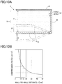
- FIG. 10A is a diagram schematically showing the vibration of an outer wall due to incident noise.
- FIG. 10B is a diagram showing a relationship between the compression ratio and wall-to-wall distance of a closed cross-sectional portion when compressed due to the vibration of an outer wall.
- FIG. 11 is a cross-sectional view showing a variation of the first embodiment.
- FIGS. 12A and 12B are a schematic diagram and a table, respectively, showing a specific example for describing a specific surface area.
- FIG. 13 is a schematic diagram for describing a production method for the double-wall panel of the first embodiment.
- FIGS. 14A and 14B are diagrams schematically showing panel structures according to Conventional Examples 1 and 2, respectively, related to the first embodiment.
- FIG. 14C is a cross-sectional view of a conventional panel structure including one of the panel structures of FIGS. 14A and 14B .
- FIG. 15 is a cross-sectional view showing a panel structure according to a second embodiment.
- FIG. 16 is a cross-sectional view showing a hollow double-wall panel of FIG. 15 .
- FIG. 17 is an enlarged view of a half portion of the hollow double-wall panel of FIG. 15 .
- FIG. 18 is a diagram showing a relationship between a thickness D and a sound power transmission loss ratio K of a core layer of a hollow double-wall panel.
- FIG. 19A is a cross-sectional view in the case where a horizontal portion is joined to a joint mating member using fastening parts.
- FIG. 19B is an enlarged view of a portion of FIG. 19A .
- FIG. 19C is a cross-sectional view showing a variation of FIG. 19B .
- FIG. 20 is a plan view of a hollow double-wall panel as viewed from above.
- FIG. 21 is a diagram showing a relationship between a sound insulation performance maintenance ratio T and an aperture ratio Y of a hollow double-wall panel.
- FIG. 22 is a cross-sectional view in the case where a joint portion of a hollow double-wall panel has a vertical portion and a horizontal portion.
- FIG. 23 is a cross-sectional view in the case where a vertical portion of a hollow double-wall panel is joined to a joint mating member using fastening parts.
- FIG. 24 is a cross-sectional view in the case where a joint portion of a hollow double-wall panel has a sloping portion.
- FIG. 25 is a cross-sectional view in the case where a sloping portion of a hollow double-wall panel is joined to a joint mating member using fastening parts.
- FIG. 26A is a cross-sectional view showing a hollow double-wall panel having two separate walls.
- FIG. 26B is an enlarged view of a portion of FIG. 26A .
- FIG. 27 is a diagram showing a relationship between a sound insulation level Q of a hollow double-wall panel and a noise frequency F.
- FIG. 28 is a cross-sectional view in the case of where hollow double-wall panels are joined together.
- the first embodiment is related to claims 1 - 15 , and is shown in FIGS. 1-14 .
- a panel structure 1 according to the first embodiment is applicable to the body of a car.
- the panel structure 1 includes a double-wall panel 5 .
- the panel structure 1 is particularly applicable to panel members (e.g., a roof panel, door panel, dashboard panel, floor panel, etc.) that form the interior of a car.
- panel members e.g., a roof panel, door panel, dashboard panel, floor panel, etc.
- the panel structure 1 is applied to a floor panel that forms a floor FL of the interior of a car.
- the panel structure 1 has the same basic configuration as that of a car body structure according to a second embodiment described below.
- the basic configuration is more highly related to the second embodiment, and therefore, will be described in greater detail in the description of the second embodiment.
- FIG. 1 is a cross-sectional view of the panel structure 1 of the first embodiment included in a car, taken along a plane perpendicular to the longitudinal direction of the car.
- the panel structure 1 is laterally symmetrical, and therefore, configurations of a center portion and one of left and right portions of the panel structure 1 in the transverse direction of a car will be described.
- the panel structure 1 includes a left and a right side sill 3 , a center tunnel 4 , and a left and a right double-wall panel 5 .
- the double-wall panels 5 each include an inner wall 22 , an outer wall 21 facing the inner wall 22 , and a core material 51 a enclosed between the inner wall 22 and the outer wall 21 .
- the side sills 3 are framework members of steel that form a left and a right end of a floor FL in the interior of a car.
- the side sills 3 are hollow inside and extend in the car longitudinal direction.
- the side sills 3 each have a body 31 and an inward protrusion 32 that protrudes from a lower portion of the body 31 inward in the car transverse direction.
- the inward protrusion 32 supports an outer end in the car transverse direction of the double-wall panel 5 .
- the center tunnel 4 is disposed at a center of the floor FL in the interior of a car, extending in the car longitudinal direction. In a cross-section thereof perpendicular to the car longitudinal direction, the center tunnel 4 is hollow and has substantially a trapezoidal shape protruding upward from the floor FL in the interior of a car.
- An exhaust pipe 6 extending in the car longitudinal direction, etc., are disposed in the center tunnel 4 .
- the center tunnel 4 has a body 41 and outward protrusions 42 that protrude from a lower portion of the body 41 outward in the car transverse direction.
- the outward protrusions 42 each support an inner end in the car transverse direction of the corresponding double-wall panel 5 .
- the inward protrusions 32 and the outward protrusions 42 have upper surfaces that are flat and have the same height for supporting the double-wall panels 5 horizontally.
- the double-wall panels 5 each include an outer wall 21 (lower wall) that is disposed in the exterior of a car, an inner wall 22 (upper wall) that is disposed in the interior of a car, vertical walls 23 (a transverse outer wall 23 o , a transverse inner wall 23 i , and if necessary, a front wall and a rear wall (not shown)) that vertically link peripheral edges of the outer wall 21 and the inner wall 22 .
- These parts of the double-wall panel 5 are substantially integrally formed in one piece by blow molding, etc., so that the double-wall panel 5 has a closed cross-sectional portion (hollow portion) 20 inside.
- the transverse outer wall 23 o and the transverse inner wall 23 i as the vertical walls 23 each include a lower vertical wall 23 a , an upper vertical wall 23 b , and a horizontal wall 23 c horizontally linking an upper end of the lower vertical wall 23 and a lower end of the upper vertical wall 23 together. These parts are integrally formed in one piece, which is in the shape of a step.
- the outer wall 21 is a wall (lower panel) through which noise enters the double-wall panel 5
- the inner wall 22 is a wall (upper wall) through which noise leaves the double-wall panel 5 , in a direction in which noise transmits from the outside of (below) the interior of a car into the interior of the car (above) (the thickness direction of the double-wall panel 5 ).
- the outer wall 21 , the inner wall 22 , and the vertical walls 23 of the double-wall panel 5 are all formed of resins.
- the outer wall 21 is formed of PP
- the inner wall 22 is formed of glass fiber-reinforced resin, so that the bending stiffness of the outer wall 21 is lower than the bending stiffness of the inner wall 22 .
- the vertical walls 23 are formed of the same PP as that of the outer wall 21 .
- the bending stiffness of the inner wall 22 is set higher than or equal to that of glass fiber-reinforced resin (3 GPa or more), and the bending stiffness of the outer wall 21 is set lower than or equal to that of PP (5000 MPa or less, preferably 2500 MPa or less, and more preferably 1500 MPa or less).
- the stiffness (elastic modulus) of the inner wall 22 is preferably set in the range of, for example, 3-15 GPa, taking into account the relationship between the mass and required performance of the inner wall 22 .
- the inner wall 22 is required to have a stiffness of 15 GPa.
- the inner wall 22 is thick, e.g., has a thickness of about 2.9 mm, the inner wall 22 is required to have a stiffness of as low as 3 GPa, which still satisfies the required performance. Therefore, if the inner wall 22 is configured to have a stiffness in the range of 3-15 GPa, it is preferable to set the thickness of the inner wall 22 to about 1.5-2.9 mm.
- a closed cross-sectional portion 20 between the outer wall 21 and the inner wall 22 is substantially completely filled with a core material 51 a and a gas 52 a (e.g., air).
- a solid layer 51 formed of the core material 51 a and a gas layer 52 formed of the gas 52 a constitute a core layer 50 .
- the core material 51 a which is formed of a fibrous substance, contains, for example, polyester, acrylic resin, nylon, polypropylene, cotton, or rayon. In this example, polyester is employed.
- the core material 51 a which is enclosed in the closed cross-sectional portion 20 and is formed of a fibrous substance, contains a large number of fibers 51 aa , most of which are aligned along a wall surface 21 a (panel surface) of the outer wall 21 (i.e., the fiber direction (longitudinal direction) of the fibers 51 aa is along the wall surface 21 a ).
- most of the fibers 51 aa of the fibrous core material 51 a are disposed substantially parallel to the wall surface 21 a of the outer wall 21 .
- an outer portion in the car transverse direction of each double-wall panel 5 is formed as a joint portion 110 to the corresponding side sill 3
- an inner portion in the car transverse direction of each double-wall panel 5 is formed as a joint portion 11 i to the center tunnel 4 .
- the joint portions 110 and 11 i are thinner than a center portion in the car transverse direction of the double-wall panel 5 .
- the outer joint portion 11 o in the car transverse direction of the double-wall panel 5 is supported by the inward protrusion 32 of the side sill 3 , while the inner joint portion 11 i in the car transverse direction of the double-wall panel 5 are supported by the outward protrusion 42 of the center tunnel 4 , so that the double-wall panel 5 spans between the side sill 3 and the center tunnel 4 .
- an adhesive material 12 is interposed between portions of the joint portion 110 of the double-wall panel 5 and the side sill 3 that face each other, and between portions of the joint portion 11 i of the double-wall panel 5 and the center tunnel 4 that face each other.
- the double-wall panel 5 is joined to the side sills 3 and the center tunnel 4 by the adhesive material 12 .
- a sound absorption layer W 1 and a skin layer W 2 are disposed in that order on an upper surface of the inner wall 22 of the double-wall panel 5 .
- the double-wall panel 5 of the first embodiment has a wall-to-wall distance (a gap between the outer wall 21 and the inner wall 22 ) in the range of 15-30 mm across the panel in all in-plane directions (the car transverse direction and the car longitudinal direction). Specifically, the double-wall panel 5 has a wall-to-wall distance of at least 15 mm at the joint portions 11 i and 11 o , which are thinner than the center portion in the car transverse direction.
- the present inventors have mainly paid attention to a spring elastic modulus k (described below) of the core layer 50 , and a stiffness ratio of the inner and outer walls 21 and 22 , etc.
- the double-wall panel 5 of the first embodiment is adapted or modified in terms of these two points so that the road noise transmission loss of the double-wall panel 5 of the first embodiment is increased compared to that of conventional double-wall panels.
- FIG. 2A is a schematic diagram showing the basis of a spring-mass-damper model representing the double-wall panel 5 , indicating how noise N entering through the outer wall 21 is transmitted before exiting through the inner wall 22 .
- FIG. 2B is a diagram showing a spring-mass-damper model representing the double-wall panel 5 .
- the mass of the outer wall 21 as an incident panel of FIG. 2B is represented by m 1 (kg)
- the mass of the inner wall 22 as an exit panel of FIG. 2B is represented by m 2 (kg)
- the spring elastic modulus of the core layer 50 i.e., how easily the gas 52 a enclosed in the closed cross-sectional portion 20 is compressed
- k N/m
- D D (N ⁇ s/m).
- the resonant frequency f rm of the double-wall panel 5 can be represented on the basis of an equation of motion of the double-wall panel 5 by:
- f rm 1 2 ⁇ ⁇ ⁇ k m e ( 1 )
- m e represents the effective mass of each of the inner and outer walls 21 and 22
- m e and k can be expressed by:
- ⁇ the density of the gas 52 a
- c the speed of sound
- d the wall-to-wall distance
- ⁇ c 2 the bulk modulus E (gas elastic modulus) of the core layer 50 .
- FIG. 14A is a schematic diagram of a panel structure 100 according to Conventional Example 1.
- FIG. 14B is a schematic diagram of a panel structure 110 according to Conventional Example 2.
- FIG. 14C is a cross-sectional view of a conventional body floor structure 120 to which the panel structure 100 of Conventional Example 1 or the panel structure 110 of Conventional Example 2 is applied.
- the panel structure 100 of Conventional Example 1 is based on a pseudo-double-wall structure 103 that includes a lower cover 101 , a steel material 102 , and a closed cross-sectional portion 103 A enclosed by the lower cover 101 and the steel material 102 , and therefore, is hollow inside.
- the double-wall structure 103 has a bolt insertion hole (not shown), etc., which reduces the hermeticity thereof.
- the panel structure 100 further includes various panels W 1 -W 3 that are stacked on the upper surface of the steel material 102 .
- the panel W 1 is a sound absorption layer
- the panel W 2 is a skin layer
- the panel W 3 which is formed of, for example, felt, is additionally provided to, together with the panels W 1 and W 2 , enhance the function of the pseudo-double-wall structure 103 .
- the panel structure 110 of Conventional Example 2 is a variation of Conventional Example 1. As shown in FIG. 14B , in the panel structure 110 , the felt W 3 is about four times as thick as Conventional Example 1, and the sound absorption layer W 1 is about seven times as thick as Conventional Example 1, so that the sound absorption effect is improved. Meanwhile, the entire panel structure 110 is about 1.15 times as thick as Conventional Example 1.
- FIG. 3 is a diagram showing a relationship between a noise frequency and a noise transmission loss (sound insulation level) caused by the panel structure of the floor FL in the interior of a car.
- a waveform La is of the panel structure 100 of Conventional Example 1
- a waveform Lb is of the panel structure 110 of Conventional Example 2.
- the noise frequency of road noise is, for example, 500 Hz or more.
- noise unpleasant to a passenger is considered to be in the frequency region of about 800-1600 Hz.
- the present inventors have paid attention to reduction of an apparent increase in the effective elastic modulus of the core layer 50 during compression (also hereinafter referred to as “spring elastic modulus decreasing means 1 ”), and decreasing of the bulk modulus E of the core layer 50 (also hereinafter referred to “spring elastic modulus decreasing means 2 ”), as specific means for decreasing the spring elastic modulus k of the core layer 50 .
- the outer wall 21 When noise initially enters the outer wall 21 as the incident panel, the outer wall 21 vibrates. In this process, when the outer wall 21 is deformed and bent into the closed cross-sectional portion 20 , the closed cross-sectional portion 20 (the core layer 50 ) is compressed due to the bending deformation, and its internal pressure increases because the closed cross-sectional portion 20 is a hermetic space.
- the present inventors have paid attention to the fact that the compression of the closed cross-sectional portion 20 (the core layer 50 ) warms and expands the gas 52 a in the core layer 50 , which leads to an apparent increase in the effective elastic modulus of the core layer 50 . Therefore, in the first embodiment, in order to reduce the apparent increase in the effective elastic modulus of the core layer 50 , the core material 51 a formed of a fibrous substance, with which the closed cross-sectional portion 20 is filled, is used to absorb heat generated in the gas 52 a due to the compression.
- the closed cross-sectional portion 20 when the closed cross-sectional portion 20 is compressed by ⁇ V from V 0 as shown in, for example, FIG. 4 , the closed cross-sectional portion 20 can be caused to undergo an isothermal change to the extent possible (see a waveform Ld in FIG. 4 ) compared to the case where the closed cross-sectional portion 20 undergoes an adiabatic change without absorption of heat by the core material 51 a (see a waveform Le in FIG. 4 ), whereby an increase in the internal pressure P of the closed cross-sectional portion 2 , i.e., an apparent increase in the effective elastic modulus of the core layer 50 , can be reduced (see P 1 ⁇ P 2 in FIG. 4 ).
- the compression ratio is higher in the case where the core material 51 a is enclosed in the closed cross-sectional portion 20 than in the case where the core material 51 a is not enclosed in the closed cross-sectional portion 20 .
- the apparent increase in the effective elastic modulus of the core layer 50 can be further reduced in the case where the core material 51 a is enclosed in the closed cross-sectional portion 20 than in the case where the core material 51 a is not enclosed in the closed cross-sectional portion 20
- the core material 51 a is preferably formed to have a dense structure, i.e., the surface area of the core material 51 a that is in contact with the gas 52 a is preferably increased.
- the specific surface area (S/V) of the core material 51 a which is defined as the surface area (S) per unit volume (V), is set to 20,000 (mm 2 /cm 3 ) or more.
- the packing density of the core material 51 a is set to 0.11 (g/cm 3 ) or less.
- the fiber thickness of the core material 51 a is set to 3 (denier) or less in order to satisfy the conditions that the specific surface area is 20,000 (mm 2 /cm 3 ) or more and the packing density is 0.11 (g/cm 3 ) or less.
- S/V specific surface area
- ⁇ represents the density (g/mm 3 ) of the fiber
- r represents the radius (mm) of the fiber
- M represents the weight (g) of the fibers in the core layer
- Vc represents the volume (cm 3 ) of the core layer.
- the specific surface area (S/V) is defined as the surface area (S) of the core material 51 a per unit volume (V).
- the specific surface area (S/V) is defined as “the length of the fiber per cm 3 ” ⁇ “the outer peripheral length of the fiber” (A).
- the length of the fiber per gram is “the volume of the fiber per gram”/the cross-section of the fiber, where “the volume of the fiber per gram” is “the reciprocal of the density of the fiber” (C). Therefore, the specific surface area can be more specifically defined as 1/(the density of the fiber ⁇ the cross-section of the fiber) ⁇ the packing density ⁇ “the outer peripheral length of the fiber” (D).
- the specific surface area (S/V) can be represented by Expression (3) on the basis of the descriptions (A)-(D).
- the denier of the fiber may be used instead of the radius r of the fiber.
- Expression (3) can be represented using the denier by replacing r by [d/( ⁇ 9,000 ⁇ ] 1/2 .
- the core material is a felt that is formed of PET fibers of 6 denier, and has a packing density of 600 g/m 2 and a thickness of 10 mm.
- the volume of the fiber per gram which is required in the calculation of “the length of the fiber per gram,” is 724 mm 3 /g, which is calculated using the density of the fiber (known polyester density: 1.38 (g/cm 3 )).
- the cross-sectional area of the fiber is 0.0000483 (mm 2 ), which is calculated using the radius r of the fiber. Based on these values, “the length of the fiber per gram” is 1,499 (m/g) according to the description (C).
- the specific surface area (7,020 (mm 2 /cm 3 )) can be calculated using the value (90,000 (mm/cm 3 ) of “the length of the fiber per unit volume” of the felt, and the value (0.078 (mm)) of “the outer peripheral length of the fiber” calculated above, according to the description (A).
- the specific surface area is 7,020 (mm 2 /cm 3 ).
- the specific surface area can be set to 20,000 (mm 2 /cm 3 ) or more.
- FIG. 5A is a schematic diagram of a double-wall panel 5 A according to an experimental example of the present invention that is a variation of the double-wall panel 5 of the first embodiment.
- the outer wall 210 is formed of an iron sheet
- the inner wall 220 is formed of a resin sheet
- the core material 51 a is formed of a fibrous substance having a specific surface area of 20,000 (mm 2 /cm 3 ).
- the core material 51 a is separated from the inner wall 220 by a gap S, while the core material 51 a is in contact with the outer wall 210 .
- FIG. 5B shows a conventional example double-wall panel 111 in which air 53 a is enclosed, instead of the core material 51 a , between the outer wall 210 formed of an iron sheet and the inner wall 220 formed of a resin sheet.
- FIG. 5C is a diagram showing a relationship between the road noise transmission loss of the double-wall panels and the frequency of noise.
- a waveform Le is of the experimental example (see FIG. 5A ) of the present invention
- ad a waveform Ld is of the conventional example (see FIG. 5B ).
- the transmission loss of the experimental example of the present invention with respect to noise having a frequency of, for example, 1,000 Hz is improved by about 5 dB compared to the conventional example.
- the transmission loss of the experimental example of the present invention with respect to the resonant frequency f rm is improved by about 15% compared to the transmission loss of the conventional example with respect to the resonant frequency f rm .
- FIG. 6 is a graph showing a relationship between the average value of transmission loss with respect to road noise (800-1600 Hz) and the specific surface area of the core material 51 a formed of a fibrous substance.
- points P 0 and P 2 indicate the average values of road noise transmission loss that are calculated from the waveforms Ld and Le, respectively, of FIG. 5C .
- the point P 0 indicates the average value of the conventional example (see FIG. 5B ).
- the point P 2 indicates the average value of the experimental example (see FIG. 5A ) in which the core material 51 a has a specific surface area of 20,000 (mm 2 /cm 3 ).
- points P 1 and P 3 indicate average values that are obtained when the core material 51 a has a specific surface area of 5,000 and 100,000 (mm 2 /cm 3 ), respectively. These average values are calculated in a manner similar to that is used for the points P 0 and P 2 .
- the double-wall panel 5 of the first embodiment is intended to achieve a transmission loss of about 50-55 dB with respect to road noise in a frequency region (800-1600 Hz) that includes frequencies of noise unpleasant to a passenger.
- the specific surface area of the core material 51 a formed of a fibrous substance is set to 20,000 (mm 2 /cm 3 ) or more.
- the table of FIG. 7 shows a relationship between the packing density of the core material 51 a and the mass per unit area of a double-wall panel, in the case where the specific surface area of the core material 51 a is set to 20,000 (mm 2 /cm 3 ).
- all double-wall panels according to a comparative example and Examples 1-3 of the first embodiment include the inner wall 22 (upper panel), the outer wall 21 (lower panel), and the core material 51 a enclosed therebetween.
- the specific surface area of the core material 51 a is set to 20,000 (mm 2 /cm 3 ).
- the packing density of the core material 51 a of each panel is set to a value shown in the table of FIG. 7 .
- a rough calculation indicates that the mass per unit area of an existing car body floor including a lower cover (thickness t: 0.6 mm, iron) and an interior mat and excluding a reinforce is 10,700 (g/m 2 ).
- the specific surface area of the core layer 50 is set to 20,000 (mm 2 /cm 3 ) or more in order to increase the transmission loss, the need to reduce the mass of the car body floor compared to the existing car body floor is satisfied.
- the specific surface area of the core layer 50 is 20,000 (mm 2 /cm 3 ), and the packing density of the core layer 50 is, for example, 0.3 (g/cm 3 ), which is higher than 0.11 (g/cm 3 ).
- the mass per unit area of the car body floor is greater than or equal to that of the existing car body floor (15,840>10,700 (g/m 2 )).
- the specific surface area of the core layer 50 is 20,000 (mm 2 /cm 3 ), and the packing density of the core layer 50 is 0.11 (g/cm 3 ), i.e., the fiber diameter of the core material 51 a is 3 (denier).
- the mass per unit area of the car body floor is smaller than that of the existing car body floor (10,140 ⁇ 10,700 (g/m 2 )).
- the specific surface area of the core layer 50 is 20,000 (mm 2 /cm 3 ) and the packing density of the core layer 50 is lower than 0.11 (g/cm 3 ), i.e., the fiber diameter of the core material 51 a is smaller than 3 (denier).
- the mass per unit area of the car body floor is smaller than that of the existing car body floor.
- the specific surface area is smaller than 20,000 (mm 2 /cm 3 ), and therefore, the above need is not satisfied.
- Japanese Patent Publication No. 2001-242873 (paragraph) describes experimental example 2 in which a fibrous substance has an average thickness of 15 (denier) and a packing density of 0.021 (g/cm 3 ).
- Example 3 in order to set the specific surface area of the core layer 50 to 20,000 (mm 2 /cm 3 ) or more in the case where the packing density of the core layer 50 is 0.024 (g/cm 3 ), close to 0.021 (g/cm 3 ), it is necessary to set the fiber diameter of the core material 51 a to 0.1 (denier) or less.
- the packing density of the fibrous substance is 0.11 (g/cm 3 ) or less, i.e., the fibrous substance has a light weight, but the fibrous substance has an extremely great average thickness (15>0.1 (denier)), and therefore, the specific surface area is much smaller than 20,000 (mm 2 /cm 3 ).
- the specific surface area is much smaller than 20,000 (mm 2 /cm 3 ).
- the double-wall panel 5 of the first embodiment is configured so that the specific surface area of the core layer 50 is 20,000 (mm 2 /cm 3 ) or more, and the packing density of the core material 51 a is 0.11 (g/cm 3 ) or less.
- the fiber diameter of the core material 51 a is 0.6 (denier).
- the core material 51 a having a fiber diameter of 0.6 (denier) can be implemented into practice. Meanwhile, if the fiber diameter of the core material 51 a is smaller than 0.1 (denier), the manufacturing cost increases.
- the fiber diameter of the core material 51 a is preferably 0.1-3 (denier), more preferably 0.1-0.6 (denier).
- the core material 51 a may be formed of a foam substance having gas permeability instead of the above fibrous substance.
- the foam substance may have, for example, an open-cell structure in which bubbles of polyurethane or porous rubber, etc., connect to each other.
- the road noise transmission loss can preferably be increased to about 44 dB or more by employing the spring elastic modulus decreasing means 1 .
- a configuration can be employed in which a gas 52 a that has a lower bulk modulus E than that of air in a stationary state is enclosed in the closed cross-sectional portion 20 (the core layer 50 ), in order to reduce the bulk modulus E of the core layer 50 .
- stationary-state air has a bulk modulus E of about 140 (kPa), and the bulk modulus E of the gas 52 a in the core layer 50 of the first embodiment is set lower than the bulk modulus E of stationary-state air.
- the bulk modulus E of a substance in this example, the gas 52 a ) indicates how difficult the substance is to compress.
- the gas 52 a that is easier to compress than stationary-state air i.e., sulfur hexafluoride (SF 6 ) gas as an easily compressible gas, is enclosed in the closed cross-sectional portion 20 (the core layer 50 ).
- stationary-state air i.e., sulfur hexafluoride (SF 6 ) gas as an easily compressible gas
- the bulk modulus E of the gas 52 a in the core layer 50 can be reduced to about 100 (kPa), which is lower than the bulk modulus E of stationary-state air (about 140 (kPa)).
- the reduction in the bulk modulus E of the gas 52 a in the core layer 50 can contributes to a decrease in the spring elastic modulus k of the core layer 50 .
- the decrease in the spring elastic modulus k of the core layer 50 can reduce the resonant frequency f rm of the double-wall panel 5 . Therefore, as a result of employing the spring elastic modulus decreasing means 2 , a transmission loss of about 40 (dB) can be obtained with respect to the frequency region of road noise.
- the easily compressible gas is not limited to sulfur hexafluoride (SF 6 ), and may, for example, be a hydrochlorofluorocarbon (HCFC) or hydrofluorocarbon (HFC), which is easily converted into gas when compressed.
- HCFC hydrochlorofluorocarbon
- HFC hydrofluorocarbon
- an easily compressible gas is enclosed in the closed cross-sectional portion 20 in order to set the bulk modulus E of the gas 52 a in the core layer 50 to a value lower than the bulk modulus E (about 140 (kPa)) of stationary-state air.
- the present disclosure is not limited to this.
- the bulk modulus E and the pressure (air pressure) have a linear relationship. Therefore, for example, air having a negative pressure may be enclosed as the gas 52 a in the closed cross-sectional portion 20 (the core layer 50 ).
- the bulk modulus E of the gas 52 a in the core layer 50 can be reduced to about 100 (kPa), which is substantially the same as when sulfur hexafluoride is enclosed as an easily compressible gas.
- the bulk modulus E of the gas 52 a in the core layer 50 can be reduced to about 70 (kPa), which is lower than when sulfur hexafluoride is enclosed as an easily compressible gas.
- the double-wall panel 5 of the first embodiment is configured to have both the spring elastic modulus decreasing means 1 that exploits the heat absorption effect of the core material 51 a , and the spring elastic modulus decreasing means 2 that causes the bulk modulus E ( ⁇ c 2 ) of the gas 52 a in the core layer 50 to be lower than the bulk modulus E of stationary-state air, whereby the spring elastic modulus k of the core layer 50 can be significantly reduced, resulting in a significant increase in transmission loss with respect to a frequency region corresponding to road noise.
- the spring elastic modulus decreasing means 2 allows a reduction in the heat absorption performance of the core material 51 a formed of a fibrous substance or foam substance in the spring elastic modulus decreasing means 1 , and therefore, the range of options of the core material 51 a can be proportionately increased.
- the spring elastic modulus decreasing means 1 allows a reduction in the decrease of the bulk modulus E of the gas 52 a in the core layer 50 in the spring elastic modulus decreasing means 2 , and therefore, the range of options of the easily compressible gas can be proportionately increased, or the negative pressure of air can be proportionately increased (i.e., air having a pressure closer to the atmospheric pressure can be used), for example.
- the double-wall panel 5 of the first embodiment may not have both of the spring elastic modulus decreasing means 1 and 2 , and may have only one of them.
- the outer wall 21 has a stiffness (bending stiffness) lower than or equal to that of PP (1500 MPa or less), and the inner wall 22 has a stiffness (bending stiffness) higher than or equal to that of glass fiber-reinforced resin (3 GPa or more), whereby the stiffness of the outer wall 21 is lower than the stiffness of the inner wall 22 .
- FIGS. 9A, 9B, and 9C are cross-sectional views schematically showing the double-wall panel 5 of the first embodiment for describing the mechanism.
- FIGS. 9A, 9B , and 9 C show states of the double-wall panel 5 that occur before, upon, and after, respectively, the noise N enters the double-wall panel 5 .
- the stiffness of the outer wall is high, the vibration of the outer wall is not likely to be induced due to the noise N entering thereinto, and the noise N entering the double-wall panel through the outer wall is likely to reach the interior of a car through the core layer and the inner wall without being damped.
- the outer wall 21 can be caused to more actively vibrate due to the noise N entering the double-wall panel 5 through the outer wall 21 , as shown in FIGS. 9A and 9B (see the outer wall 21 indicated by an imaginary line in FIG. 9B ).
- the outer wall 21 When the outer wall 21 thus vibrates, the outer wall 21 is deformed and bent into a convex shape toward the closed cross-sectional portion 20 (see the outer wall 21 indicated by an imaginary line in FIG. 9B ), the energy of sound (the kinetic energy of gas molecules 52 aa (air molecules) due to transmission of sound) that is transmitted in the core layer 50 from the outer wall 21 toward the inner wall 22 (upward) is transmitted in in-plane directions W (directions perpendicular to the thickness direction of the double-wall panel 5 ) as shown in FIG. 9C , instead of being transmitted directly toward the interior of a car.
- in-plane directions W directions perpendicular to the thickness direction of the double-wall panel 5
- the gas molecules 52 aa in the core layer 50 are compressed in a thickness direction Y (vertical direction) to actively collide the inner wall 22 .
- the gas molecules 52 aa compressed in the thickness direction Y collide the inner wall 22 and then diffuse in the in-plane directions W, i.e., the motion toward the inner wall 22 is converted into the motion in the in-plane directions W.
- the motion in the in-plane directions W of the gas molecules 52 aa in the core layer 50 causes friction between the gas molecules 52 aa (particles) and the core material 51 a formed of a fibrous substance, so that the energy of sound is converted into thermal energy, i.e., the energy of sound can be damped. This makes it more difficult for the noise N to penetrate through the double-wall panel 5 and reach the interior of a car.
- the vibration of the outer wall 21 due to the incident noise N is a fundamental vibration, having a single crest or trough (half the wavelength).
- the present disclosure is not limited to this.
- the vibration of the outer wall 21 may be an n-th harmonic vibration (n is a natural number of two or more). In this case, the same effect can be achieved.
- the vertical walls 23 are mostly formed of the same PP material as that of the outer wall 21 .
- the vertical wall 23 is mostly formed of a material having a lower stiffness than that of the inner wall 22 , such as PP having the same stiffness as that of the outer wall 21 , sound that is transmitted through the vertical wall 23 to reach the interior of a car can be more effectively damped.
- the vertical wall 23 is mostly formed of a material having a lower stiffness than that of the inner wall 22 , the present disclosure is not limited to this.
- the vertical wall 23 may be formed of a material having a higher stiffness than that of the outer wall 21 .
- the vertical wall 23 may be formed of a material having a stiffness similar to that of the inner wall 22 .
- the support (linking) stiffness between the outer wall 21 and the inner wall 22 can be increased.
- the outer wall 21 and the inner wall 22 have the same mass.
- both the mass ratio and stiffness ratio of the outer wall 21 to the inner wall 22 can contribute to an increase in the road noise transmission loss.
- the fiber direction of the core material 51 a formed of a fibrous substance is substantially parallel to the wall surface 21 a (panel surface) of the outer wall 21 (see the enlarged view of the X portion in FIG. 1 ), and therefore, the vibration of the outer wall 21 caused by the noise N entering the double-wall panel 5 through the outer wall 21 is not disturbed by the core material 51 a formed of a fibrous substance contained in the closed cross-sectional portion 20 (i.e., the vibration of the outer wall 21 is less damped).
- the outer wall 21 can actively vibrate, whereby the effect of damping the kinetic energy of gas molecules contained in the gas layer 52 can be enhanced.
- the wall-to-wall distance (the gap between the outer wall 21 and the inner wall 22 ) is in the range of 15-30 mm across the panel in all in-plane directions W.
- the closed cross-sectional portion 20 is compressed at a compression ratio ( ⁇ V/V), where V represents the volume of the closed cross-sectional portion 20 , and ⁇ V represents a decrease in the volume of the closed cross-sectional portion 20 caused by the depression or displacement of the outer wall 21 into the closed cross-sectional portion 20 .
- the compression ratio ( ⁇ V/V) of the closed cross-sectional portion 20 corresponds to the spring elastic modulus k of the core layer 50 (how easily the core layer 50 is compressed).
- the relationship between the compression ratio ( ⁇ V/V) and the wall-to-wall distance (d) is shown in a graph of FIG. 10B .
- the wall-to-wall distance d of the double-wall panel 5 is set in the range of, for example, 15-30 mm, as described above.
- the average value of the road noise transmission loss with respect to the frequency region of 800-1600 Hz can be increased to about 44 dB.
- the spring elastic modulus decreasing means 1 and 2 are employed, and the stiffness of the outer wall 21 is set lower than the stiffness of the inner wall 22 , the average value of the road noise transmission loss with respect to the frequency region of 800-1600 Hz can be increased to, for example, about 50-55 dB in the double-wall panel 5 of the first embodiment, as indicated by a waveform Lc of FIG. 3 .
- the panels 101 , 102 , and W 1 -W 3 , and the closed cross-sectional portion 103 A have separate functions.
- these functions are integrated together, and therefore, the panel thickness can be reduced to about half the thickness of Conventional Example 1.
- FIG. 3 is of the double-wall panel 5 of the first embodiment
- FIG. 2C is a schematic diagram of the double-wall panel 5 of the first embodiment for comparison with FIGS. 14A and 14B .
- FIG. 11 schematically shows a double-wall panel 5 B as a variation of the first embodiment.
- a honeycomb material 7 that is a stiff material having a stiffness higher than or equal to the stiffness of the inner wall 22 may be interposed between the core material 51 a formed of a fibrous substance and the inner wall 22 .
- the core layer 50 including the core material 51 a formed of a fibrous substance is disposed in a portion of the closed cross-sectional portion 20 closer to the outer wall 21
- the honeycomb material 7 is disposed in a portion of the closed cross-sectional portion 20 closer to the inner wall 22 .
- the honeycomb material 7 is formed of a steel sheet having, on a surface thereof, a honeycomb structure including hexagonal concave portions 71 and hexagonal convex portions 72 adjoining each other without a gap.
- the honeycomb material 7 disposed in a portion of the closed cross-sectional portion 20 closer to the inner wall 22 can increase the stiffness of such a portion.
- the core layer 50 disposed in a portion of the closed cross-sectional portion 20 closer to the outer wall 21 can enhance the above advantage that is provided by the outer wall 21 having a lower stiffness than that of the inner wall 22 , i.e., can increase the motion of air in the core layer 50 caused by the vibration of the outer wall 21 when sound enters through the outer wall 21 , and thereby accelerate the conversion of the energy of sound into kinetic energy, resulting in an improvement in the sound damping effect.
- the stiff material is not limited to the honeycomb material 7 , and may be one that has a stiffness higher than or equal to that of the inner wall 22 .
- the stiff material may be one that has a base portion, and a plurality of concave or convex ribs that are disposed on the base portion, facing the inner wall 22 .
- the double-wall panel 5 of the first embodiment is formed, by blow molding, etc., into a hollow shape having the closed cross-sectional portion 20 (hollow portion).
- the production method for the double-wall panel of the present disclosure is not limited to integral forming using blow molding.
- the double-wall panel of the present disclosure may be produced using other techniques.
- a box-shaped object 61 including the lower wall 21 and the vertical walls 23 but not the upper wall 22 of the double-wall panel 5 and having an upper opening 61 a is formed, and a fibrous substance ( 51 a ) as the core material 51 a is inserted into the box-shaped object 61 through the opening 61 a (step 1 indicated by an arrow 1 in FIG. 13 ).
- step 2 is preferably performed with the honeycomb material 7 previously attached to the back surface of the upper wall 22 (not shown).
- the honeycomb material 7 is formed of a steel sheet.
- the honeycomb material 7 may be attached to the back surface of the upper wall 22 by welding.
- the entire double-wall panel 5 including the core layer (fibrous substance ( 51 a )) is joined to a metal framework member of a car body by welding, etc. (step 3 indicated by an arrow 3 of FIG. 13 ).
- the side sill 3 as a framework member of a car body may be formed of an extruded aluminum material instead of steel.
- the outward protrusion 42 is a framework member, to which a tunnel side frame is typically applicable.
- the outward protrusion 42 may have a configuration similar to that of the side sill 3 , or may be formed of aluminum.
- FIGS. 15-28 The second embodiment, which is related to claims 16 - 20 , is shown in FIGS. 15-28 .
- parts are indicated by reference characters in a perspective different from that of the first embodiment.
- a panel structure 1 according to the second embodiment is applicable to a car body as with the first embodiment.
- the panel structure 1 includes a hollow double-wall panel 5 as a double-wall panel.
- the panel structure 1 is particularly applicable to panel members (e.g., a roof panel, door panel, dashboard panel, floor panel, etc.) that form the interior of a car.
- panel members e.g., a roof panel, door panel, dashboard panel, floor panel, etc.
- the panel structure 1 includes a left and a right side sill (a joint mating member or framework member) 3 , a center tunnel (joint mating member) 4 , and a left and right hollow double-wall panel 5 .
- the hollow double-wall panel 5 as a double-wall panel includes a wall 51 as an inner wall, a wall 52 as an outer wall facing the wall 51 , and a core material 53 a enclosed between the two walls 51 and 52 .
- the core material 53 a has at least a predetermined thickness across the panel in all in-plane directions (the car transverse direction and the car longitudinal direction) of the walls 51 and 52 .
- the core material 53 a of the second embodiment has a specific surface area of 20,000 (mm 2 /cm 3 ) or more, where the specific surface area is defined as a surface area per unit volume. See the first embodiment for specific settings.
- the left and right the side sills 3 which are formed of, for example, a metal, are framework members that form a left and a right end of the floor FL in the interior of a car, and support outer ends in the car transverse direction of the hollow double-wall panels 5 .
- the left and right side sills 3 are disposed at the left and right ends of the floor FL in the interior of a car, are hollow inside, exend in the car longitudinal direction, and are laterally symmetrical.
- the side sill 3 has, for example, substantially an L-shaped cross-section (a cross-section perpendicular to the car longitudinal direction).
- the side sill 3 has a vertical wall 31 having a rectangular cross-section, and a protruding portion 32 having, for example, a rectangular cross-section that protrudes from a lower portion of the vertical wall 31 inward in the car transverse direction.
- the protruding portion 32 is joined to the hollow double-wall panel 5 .
- the protruding portion 32 is also hereinafter referred to as the joint portion 32 .
- the internal space of the side sill 3 is divided into a plurality of (e.g., three) closed spaces Sp, Sq, and Sr by partition walls provided in the side sill 3 .
- the closed spaces Sp, Sq, and Sr are vertically arranged side by side, for example.
- the bottom closed space Sp has a rectangular cross-sectional shape (i.e., a cross-sectional shape of a cross-section perpendicular to the car longitudinal direction) that is wide in the car transverse direction, including a lower portion of the vertical wall 31 and the entire protruding portion 32 .
- the top closed space Sr and the middle closed space Sq each have a cross-sectional shape (i.e., a cross-sectional shape of a cross-section perpendicular to the car longitudinal direction) that is one of two upper and lower portions obtained by horizontally dividing an upper portion (i.e., a portion excluding the lower portion of the vertical wall 31 ) of the vertical wall 31 into two.
- the rectangular cross-sectional shapes of the closed spaces Sr and Sq have the same transverse width and are narrower than the bottom closed space Sr.
- the center tunnel 4 is formed of, for example, a metal.
- An exhaust pipe (not shown) in which exhaust gas from an engine (not shown) mounted in the engine room of a car flows, or a propeller shaft (not shown) that transmits the power of the engine to the rear wheels of a car, etc., is inserted into the center tunnel 4 .
- the center tunnel 4 supports the inner ends in the car transverse direction of the hollow double-wall panels 5 .
- the center tunnel 4 is disposed at a middle of the floor FL in the interior of a car, extending in the car longitudinal direction.
- the center tunnel 4 has, for example, a cross-sectional shape (i.e., a cross-sectional shape of a cross-section perpendicular to the car longitudinal direction) that is hollow and substantially trapezoidal, and protrudes upward from the floor FL in the interior of a car.
- a cross-sectional shape i.e., a cross-sectional shape of a cross-section perpendicular to the car longitudinal direction
- the center tunnel 4 includes a tunnel body 41 and a tunnel cover 42 .
- the tunnel body 41 extends in the car longitudinal direction.
- the tunnel body 41 has a cross-sectional shape (i.e., a cross-sectional shape of a cross-section perpendicular to the car longitudinal direction) that is substantially squared-C open downward, i.e., has a top wall 411 and a left and a right side wall 412 .
- the top wall 411 is formed in the shape of, for example, a flat plate.
- the left and right side walls 412 are extended downward from left and right ends of the top wall 411 .
- a distance between the left and right side walls 412 gradually becomes wider downward, i.e., slopes outward in the car transverse direction, for example.
- a joint portion 413 for joining to the corresponding hollow double-wall panel 5 is provided on one of the opposite main surfaces of each side wall 412 that faces outward in the car transverse direction.
- the joint portion 413 protrudes outward in the car transverse direction from a lower portion of the main surface of the side wall 412 facing outward in the car transverse direction, and is extended in the car longitudinal direction.
- the joint portion 413 has a cross-sectional shape (i.e., a cross-sectional shape of a cross-section perpendicular to the car longitudinal direction) that is, for example, substantially rectangular, and is, for example, hollow inside.
- the height of the upper surface of the joint portion 413 is the same as the height of the upper surface of the joint portion 32 of the side sill 3 facing that joint portion 413 so that the hollow double-wall panel 5 can be supported horizontally.
- the tunnel cover 42 which is used to close the bottom opening of the tunnel body 41 , is formed of an elongated flat plate extending in the car longitudinal direction.
- the tunnel cover 42 is disposed at the bottom opening of the tunnel body 41 , and is fixed to the tunnel body 41 using a fastening part (not shown), such as a bolt.
- peripheral portions of the two walls 51 and 52 are joined together, and a core layer 53 is formed in a closed space Sa between the two walls 51 and 52 .
- the walls 51 and 52 are formed of, for example, a resin (e.g., a thermosetting resin, such as polyester resin, or a thermoplastic resin, such as polypropylene).
- the hollow double-wall panel 5 is formed in the shape of a plate as a whole.
- the peripheral portions of the two walls 51 and 52 are joined together at, for example, peripheral portions of the hollow double-wall panel 5 .
- peripheral portions of the two walls 51 and 52 are joined together by being integrally formed.
- a molten resin as a material for the walls 51 and 52 is sprayed onto a mold for the hollow double-wall panel 5 to integrally form the two walls 51 and 52 . This technique is called blow molding.
- the core layer 53 is formed by filling the closed space Sa of the hollow double-wall panel 5 with the core material 53 a .
- the core layer 53 has at least one of sound insulating properties and heat insulating properties (in the second embodiment, both of them).
- the core material 53 a is formed of, for example, a fibrous substance or a substance having open-cell structure, in which a solid phase and a gas phase coexist.
- the gas phase may, for example, be a gas that is highly easily compressible, such as air or SF 6 (sulfur hexafluoride) gas, or various other gases, such as xenon gas and krypton gas.
- the gas phase may be a negative pressure gas or vacuum.
- the hollow double-wall panel 5 which is formed in the shape of, for example, a flat plate, includes a panel body 54 , and edges 55 that are a portion other than the panel body 54 .
- the edges 55 function as joint portions for joining to the joint mating members (e.g., the side sill 3 and the center tunnel 4 ).
- the edges 55 are also hereinafter referred to as the joint portions 55 .
- the closed space Sa in the hollow double-wall panel 5 is integrally formed from the inside of the panel body 54 to the inside of the edge 55
- the core layer 53 is integrally formed from the inside of the panel body 54 to the inside of the edge 55 .
- the insides of the panel body 54 and the edge 55 are filled with the core material 53 a.
- the panel body 54 is formed in the shape of, for example, a flat plate.
- the joint portions 55 are horizontal portions 55 H in the shape of a flat plate that protrude outward in a horizontal direction with respect to the panel body 54 from the opposite ends in the car transverse direction of the panel body 54 .
- the horizontal portions 55 H are provided at a predetermined depth from the lower main surface the panel body 54 in the thickness direction of the panel body 54 , so that there is a level difference (step) between the panel body 54 and each horizontal portion 55 H.
- the joint portion 55 is provided at only the opposite ends in the car transverse direction of the panel body 54 , but not at the opposite ends in the car longitudinal direction of the panel body 54 .
- the joint portion 55 may be provided at the opposite ends in the car longitudinal direction of the panel body 54 .
- a sound absorption layer W 1 and a skin layer W 2 are provided in that order on the upper surface (i.e., the upper surface of the upper wall 51 ) of the hollow double-wall panel 5 with the sound absorption layer W 1 closer to the upper surface.
- the sound absorption layer W 1 is formed of a material that absorbs sound (e.g., felt, urethane foam, etc.).
- the skin layer W 2 which is used to protect the surface of the hollow double-wall panel 5 or improve the appearance of the surface of the hollow double-wall panel 5 , is formed of, for example, synthetic fibers or rubber.
- the hollow double-wall panel 5 thus configured is joined between the side sill 3 and the center tunnel 4 with the double-wall panel 5 mounted from above.
- a lower surface (i.e., a lower surface in the thickness direction of the horizontal portion 55 H) 55 a of the outer joint portion 55 in the car transverse direction of the hollow double-wall panel 5 is put on top of an upper surface (i.e., a joint surface) 32 a of the joint portion 32 of the side sill 3 , so that the core material 53 a in the joint portion 55 covers the upper surface 32 a of the side sill 3 .
- an outer side surface 55 c in the car transverse direction of the joint portion 55 adjoins an inner side surface 31 a in the car transverse direction of the vertical wall 31 of the side sill 3
- an outer side surface 54 a in the car transverse direction of the panel body 54 adjoins an inner side surface 32 b in the car transverse direction of the joint portion 32 of the side sill 3 .
- the inner lower surface 55 a of the joint portion 55 in the car transverse direction of the hollow double-wall panel 5 is put on top of an upper surface (i.e., a joint surface) 413 a of the joint portion 413 of the center tunnel 4 , so that the core layer 53 (i.e., the core material 53 a ) in the joint portion 55 covers the upper surface 413 a of the center tunnel 4 .
- outer side surface 55 c in the car transverse direction of the joint portion 55 adjoins an outer side surface 412 a in the car transverse direction of the side wall 412 of the center tunnel 4
- the inner side surface 54 a in the car transverse direction of the panel body 54 adjoins the outer side surface 413 a in the car transverse direction of the joint portion 413 of the center tunnel 4 .
- the core material 53 a in the joint portion 55 covers the upper surface (i.e., a joint surface) 32 a of the side sill 3 on one side of the hollow double-wall panel 5 , and the upper surface (i.e., a joint surface) 413 a of the center tunnel 4 on the other side of the hollow double-wall panel 5 .
- sound insulating properties and heat insulating properties are ensured at the joint portions between the hollow double-wall panel 5 , and the side sill 3 and the center tunnel 4 .
- an adhesive material F is applied to gaps at the joint portion between the hollow double-wall panel 5 and the side sill 3 (i.e., a gap between the surfaces 31 a and 55 c , a gap between the surfaces 32 a and 55 a , and a gap between the surfaces 32 b and 54 a ).
- An adhesive material F is also applied to gaps at the joint portion between the hollow double-wall panel 5 and the center tunnel 4 (i.e., a gap between the surfaces 412 a and 55 c , a gap between the surfaces 413 a and 55 a , and a gap between the surfaces 413 b and 54 a ).
- the hollow double-wall panel 5 is joined to the side sill 3 and the center tunnel 4 by these adhesive materials F.
- FIG. 18 is a diagram showing a relationship between a thickness D (mm) of the core layer 53 and sound insulating performance (e.g., a sound power transmission loss ratio K (%)) of the hollow double-wall panel 5 .
- the sound power transmission loss ratio K refers to the ratio of sound power transmitted through the hollow double-wall panel 5 , where the ratio K is 100% in the case where the thickness D of the core layer 53 is 0 mm. As the sound power transmission loss ratio K increases, the sound insulating performance of the hollow double-wall panel 5 increases.
- the sound power transmission loss ratio K still increases, but has almost reached a plateau.
- the sound power transmission loss ratio K is reduced by less than 25%, compared to the sound power transmission loss ratio K in the case where the thickness D of the core layer 53 is 30 mm, and therefore, is maintained at a relatively high value.
- the sound power transmission loss ratio K tends to decrease rapidly.
- the thickness D of the core layer 53 be 15-30 mm Note that in the case where greater importance is put on the sound insulating properties of the hollow double-wall panel 5 , the thickness D of the core layer 53 may be set to as thick as 50 mm. In the case where greater importance is put on the thin thickness of the hollow double-wall panel 5 , the thickness D of the core layer 53 may be set to as thin as 15 mm.
- the edges 55 of the hollow double-wall panel 5 are joined to the joint surfaces of joint mating members (e.g., the joint surface 32 a of the side sill 3 and the joint surface 413 a of the center tunnel 4 ).
- joint mating members e.g., the joint surface 32 a of the side sill 3 and the joint surface 413 a of the center tunnel 4 .
- the peripheral edges of the two walls 51 and 52 are joined together, the closed space Sa between the two walls 51 and 52 is filled with the core material 53 a , and the insides of the edges 55 of the hollow double-wall panel 5 are also filled with the core material 53 a .
- the core material 53 a contained in the edge 55 of the hollow double-wall panel 5 covers the joint surface of the joint mating member.
- the inside of the edge 55 of the hollow double-wall panel 5 is also filled with the core material 53 a , and therefore,
- the core material 53 a contained in the edge 55 of the hollow double-wall panel 5 covers the joint surface of the joint mating member. Therefore, even if the inside of the joint mating member is not filled with a core material, sound insulating properties and heat insulating properties can be ensured at the joint portion between the edge 55 of the hollow double-wall panel 5 and the joint surface of the joint mating member.
- the joint mating members for the hollow double-wall panel 5 are a framework member (e.g., the side sill 3 ) and a reinforcement member (e.g., the center tunnel 4 ) of a car body. Therefore, the hollow double-wall panel 5 can be preferably used as a floor panel in the interior of a car.
- the edges (i.e., joint portions) 55 of the hollow double-wall panel 5 are joined to the joint surfaces 32 a and 413 a of the side sill 3 and the center tunnel 4 (joint mating members) by adhesion. Therefore, it is not necessary to provide a joint hole in the hollow double-wall panel 5 . Therefore, the hollow double-wall panel 5 can be joined to the joint mating members while the hermeticity of the closed space Sa in the hollow double-wall panel 5 is ensured.
- the thickness of the core layer 53 formed by filling the closed space Sa of the hollow double-wall panel 5 with the core material 53 a is in the range of 7-50 mm Therefore, both sound insulating properties and thin thickness of the hollow double-wall panel 5 can be simultaneously achieved.
- the thickness of the core layer 53 of the hollow double-wall panel 5 is 7 mm
- at least the minimum sound insulating properties of the hollow double-wall panel 5 required in practical use can be ensured, while the thickness of the hollow double-wall panel 5 can be substantially minimized
- the sound insulating properties of the hollow double-wall panel 5 can be substantially maximized, while the thickness of the hollow double-wall panel 5 is set to the maximum of the practical thickness range.
- the two walls 51 and 52 are formed of, for example, a thermosetting resin or thermoplastic resin. Therefore, the heat resistance of the hollow double-wall panel 5 can be improved compared to general-purpose resins, and the weight of the hollow double-wall panel 5 can be reduced, while a sufficient strength of the hollow double-wall panel 5 is ensured.
- the two walls 51 and 52 may be formed of aluminum, magnesium, or iron instead of a thermosetting resin or thermoplastic resin. Even in this case, a sufficient strength of the hollow double-wall panel 5 can be ensured. In the case where the two walls 51 and 52 may be formed of aluminum or magnesium, the weight of the hollow double-wall panel 5 can be reduced. In the case where the two walls 51 and 52 may be formed of aluminum or iron, a sufficient heat resistance of hollow double-wall panel 5 can be ensured.
- the two walls 51 and 52 may be formed of at least one of a thermosetting resin, a thermoplastic resin, aluminum, magnesium, and iron. Alternatively, the two walls 51 and 52 may be formed of the same or different one of the above materials.
- peripheral edges of the two walls 51 and 52 are joined together by being integrally formed. Therefore, the hermeticity of the two walls 51 and 52 can be increased at the peripheral edges thereof.
- the hollow double-wall panel 5 has the edges (i.e., joint portions) 55 and the panel body 54 excluding the edges 55 .
- the edge 55 has the horizontal portion 55 H that protrudes outward in the horizontal direction with respect to the panel body 54 .
- the surface 55 a in the thickness direction of the horizontal portion 55 H is joined to the joint surface of a joint mating member (e.g., the joint surface 32 a of the side sill 3 or the joint surface 413 a of the center tunnel 4 ).
- the hollow double-wall panel 5 can be substantially prevented from being disjoined from the joint mating member.
- the horizontal portion 55 H is thinner than the panel body 54 , and is disposed at a predetermined depth from the lower surface of the panel body 54 in the thickness direction of the panel body 54 , so that there is a level difference (step) between the horizontal portion 55 H and the panel body 54 .
- the horizontal portion 55 H may have the same thickness as that of the panel body 54 so that the upper and lower surfaces of the horizontal portion 55 H are flush with the upper and lower surfaces, respectively, of the panel body 54 , i.e., there is not a level difference (step) therebetween.
- the hollow double-wall panel 5 and a joint mating member are mechanically joined together using fastening parts 6 (a bolt 6 a and a nut 6 b ).
- a through-hole 55 b is provided in the horizontal portion 55 H of the edge 55 of the hollow double-wall panel 5 .
- the through-hole 55 b penetrates through the horizontal portion 55 H in the thickness direction of the horizontal portion 55 H.
- a through-hole 32 s is provided in the joint surface 32 a (i.e., an upper wall of the joint portion 32 ) of the side sill 3 .
- the nut 6 b is fixed to a back surface of the joint surface 32 a of the side sill 3 (i.e., a back surface of the upper wall of the joint portion 32 ).
- the threaded hole of the nut 6 b is aligned with the through-hole 32 s.
- the bolt 6 a is inserted into the through-hole 55 b of the horizontal portion 55 H of the hollow double-wall panel 5 and the through-hole 32 s of the joint surface 32 a of the side sill 3 successively, and is then screwed into the nut 6 b .
- This fastening allows the hollow double-wall panel 5 and the joint mating member (e.g., the side sill 3 ) to be mechanically joined together by the fastening parts 6 .
- a sealing material G is provided around the head 6 c of the bolt 6 a to seal a gap between the head 6 c of the bolt 6 a and an upper surface (i.e., an upper surface of the edge 55 ) of the horizontal portion 55 H.
- the sealing material G ensures sufficient hermeticity of the closed space Sa in the hollow double-wall panel 5 .
- the sealing material G may be provided between a back surface of the head 6 c of the bolt 6 a and a peripheral portion of the through-hole 55 b at the upper surface of the horizontal portion 55 H.
- an adhesive material F is applied to a joint portion between the hollow double-wall panel 5 and a joint mating member (e.g., the side sill 3 ).
- the adhesive material F also joins the hollow double-wall panel 5 to the joint mating member.
- the adhesive material F seals the gap between the through-hole 55 b and the bolt 6 a on the lower surface (i.e., a joint surface) 55 a of the edge 55 of the hollow double-wall panel 5 . This also ensures sufficient hermeticity of the closed space Sa in the hollow double-wall panel 5 .
- the edge 55 of the hollow double-wall panel 5 is joined to the joint surface of a joint mating member (e.g., the joint surface 32 a of the side sill 3 ) by the fastening parts 6 . Therefore, the hollow double-wall panel 5 and the joint mating member can be mechanically joined together (i.e., with a sufficient joining strength).
- a joint mating member e.g., the joint surface 32 a of the side sill 3
- the horizontal portion 55 H of the edge 55 of the hollow double-wall panel 5 is fastened to the joint surface of a joint mating member using the fastening parts 6 . Therefore, by the horizontal portion 55 H being joined to the joint mating member, the edge 55 of the hollow double-wall panel 5 can be mechanically joined to the joint surface of the joint mating member.
- the gap between the edge 55 of the hollow double-wall panel 5 (e.g., the upper surface of the edge 55 ) and a fastening part 6 (e.g., the head 6 c of the bolt 6 a ) is sealed by the sealing material G. Therefore, even in the case where the through-hole 55 b into which the fastening part 6 is inserted is provided in the edge 55 of the hollow double-wall panel 5 , the hermeticity of the closed space Sa in the hollow double-wall panel 5 can be ensured.
- the joining of the hollow double-wall panel 5 to the side sill 3 has been described as an example, the hollow double-wall panel 5 may be similarly joined to the center tunnel 4 using the fastening parts 6 .
- the adhesive material F may not be provided in the gap at the joint portion between the hollow double-wall panel 5 and the side sill 3 .
- Variation 2 is a modification of Variation 1 in which the through-hole 55 b of the edge 55 of the hollow double-wall panel 5 has the following relationship with the surface area of the hollow double-wall panel 5 .
- the aperture ratio Y is set to less than 1%.
- the opening area S 2 is defined as the sum of the opening areas of the openings on one side of all the through-holes 55 b.
- FIG. 21 is a diagram showing a relationship between a sound insulation performance maintenance ratio T (%) of the hollow double-wall panel 5 and the aperture ratio Y (%).
- the sound insulation performance maintenance ratio T refers to at what level the sound insulation performance of the hollow double-wall panel 5 is maintained.
- the sound insulation performance maintenance ratio T is 100% in the case where the aperture ratio Y is 0% (i.e., the through-hole 55 b is absent in the hollow double-wall panel 5 ), and 0% in the case where the aperture ratio Y is 100%.
- the aperture ratio Y is preferably set to less than 1% in order to maintain the sound insulation performance maintenance ratio T at a high value.
- the aperture ratio Y of the through-hole 55 b provided in the hollow double-wall panel 5 is less than 1%. Therefore, about 70% or more (i.e., sufficient sound insulating properties in practical use) of the sound insulating properties that are achieved when the hollow double-wall panel 5 is perfectly hermetically sealed (i.e., the through-hole 55 b is absent) can be ensured.
- the joint portion (i.e., an edge) 55 of the hollow double-wall panel 5 includes only the horizontal portion 55 H.
- the joint portion (i.e., an edge) 55 of the hollow double-wall panel 5 includes a horizontal portion 55 H and a vertical portion 55 V.
- the vertical portion 55 V is in the shape of a plate that protrudes upward in the vertical direction with respect to the panel body 54 , from an end in the car transverse direction of the panel body 54 of the hollow double-wall panel 5 .
- the horizontal portion 55 H is in the shape of a plate that protrudes from an upper end of the vertical portion 55 V, outward in the horizontal direction with respect to the panel body 54 .
- the horizontal portion 55 H is disposed at a predetermined depth from the lower surface 54 D of the panel body 54 upward in the thickness direction of the panel body 54 , i.e., there is a level difference (step) between the horizontal portion 55 H and the lower surface 54 D of the panel body 54 .
- the panel body 54 is disposed at a predetermined depth from an upper surface 55 i of the horizontal portion 55 H downward in the thickness direction of the horizontal portion 55 H, i.e., there is a level difference (step) between the panel body 54 and the upper surface 55 i of the horizontal portion 55 H.
- the thickness of the panel body 54 is, for example, smaller than the thickness of the panel body 54 of the second embodiment.
- an outer side surface 55 d in the car transverse direction of the vertical portion 55 V i.e., an outer surface in the thickness direction of the vertical portion 55 V
- the inner side surface (i.e., a joint surface) 32 b in the car transverse direction of the joint portion 32 of the side sill 3 so that the core material 53 a in the vertical portion 55 V covers the side surface 32 b of the side sill 3 .
- the outer side surface 55 c in the car transverse direction of the horizontal portion 55 H of the hollow double-wall panel 5 adjoins the inner side surface 31 a in the car transverse direction of the vertical wall 31 of the side sill 3 .
- the core material 53 a in the joint portion 55 of the hollow double-wall panel 5 covers the joint surfaces 32 a and 32 b of the side sill 3 , and therefore, sound insulating properties and heat insulating properties can be ensured at the joint portion between the hollow double-wall panel 5 and the side sill 3 .
- an adhesive material F is applied to gaps at the joint portion between the hollow double-wall panel 5 and the side sill 3 (i.e., a gap between the surfaces 31 a and 55 c , a gap between the surfaces 32 a and 55 a , and a gap between the surfaces 32 b and 55 d ).
- the hollow double-wall panel 5 is joined to the side sill 3 by the adhesive material F.
- an inner joint portion i.e., a joint portion joined to the center tunnel 4 ) 55 in the car transverse direction of the hollow double-wall panel 5 is similarly formed, and is similarly joined to the center tunnel 4 .
- the joint portion (i.e., an edge) 55 of the hollow double-wall panel 5 has the vertical portion 55 V protruding vertically with respect to the panel body 54 , and the outer side surface 55 d in the thickness direction of the vertical portion 55 V is joined to the joint surface of a joint mating member (e.g., the joint surface 32 b of the side sill 3 ). Therefore, even when a load is applied to the joint surface in the horizontal direction (i.e., the thickness direction of the vertical portion 55 V) with respect to the hollow double-wall panel 5 , the vertical portion 55 V is hooked by the joint surface of the joint mating member, and therefore, the hollow double-wall panel 5 is substantially prevented from being disjoined from the joint mating member.
- a joint mating member e.g., the joint surface 32 b of the side sill 3
- the joint portion (i.e., an edge) 55 of the hollow double-wall panel 5 includes the vertical portion 55 V and the horizontal portion 55 H.
- the joint portion (i.e., an edge) 55 of the hollow double-wall panel 5 may include only the vertical portion 55 V.
- Variation 4 is a modification of Variation 3 in which the hollow double-wall panel 5 and the side sill 3 (joint mating member) are mechanically joined together using fastening parts 7 (a bolt 7 a and a nut 7 b ).
- a through-hole 55 e is provided in the vertical portion 55 V of the joint portion (i.e., an edge) 55 of the hollow double-wall panel 5 .
- the through-hole 55 e penetrates through the vertical portion 55 V in the thickness direction of the vertical portion 55 V.
- a through-hole 32 t is provided in the side surface (i.e., a joint surface) 32 b of the joint portion 32 of the side sill 3 .
- the nut 7 b is fixed to a back surface (i.e., a back surface of the side wall of the joint portion 32 ) facing the joint surface 32 b of the side sill 3 .
- the threaded hole of the nut 7 b is aligned with the through-hole 32 t.
- the bolt 7 a is inserted into the through-hole 55 e of the vertical portion 55 V of the hollow double-wall panel 5 and the through-hole 32 t of the side surface 32 b of the side sill 3 successively, and is then screwed into the nut 7 b .
- This fastening allows the hollow double-wall panel 5 and a joint mating member (e.g., the side sill 3 ) to be mechanically joined together by the fastening parts 7 .
- a sealing material G is provided around the head 7 c of the bolt 7 a (i.e., a fastening part 7 ) to seal a gap between the head 7 c of the bolt 7 a and the vertical portion 55 V (i.e., the edge 55 ).
- the sealing material G ensures sufficient hermeticity of the closed space Sa in the hollow double-wall panel 5 .
- an adhesive material F is applied to a joint portion between the hollow double-wall panel 5 and a joint mating member (e.g., the side sill 3 ).
- the adhesive material F also joins the hollow double-wall panel 5 to the joint mating member.
- the adhesive material F seals a gap between the through-hole 55 e and the bolt 7 a at the side surface (i.e., a joint surface) 55 d of the vertical portion 55 V of the hollow double-wall panel 5 . This also ensures sufficient hermeticity of the closed space Sa in the hollow double-wall panel 5 .
- the vertical portion 55 V of the joint portion (i.e., an edge) 55 of the hollow double-wall panel 5 is fastened to the joint surface of a joint mating member (e.g., the side surface 32 b of the side sill 3 ) by the fastening parts 7 . Therefore, the joint portion 55 of the hollow double-wall panel 5 can be mechanically fixed to the joint mating member using the vertical portion 55 V joined to the joint mating member.
- the ends of the fastening parts 7 are prevented from protruding in the thickness direction of the panel body 54 .
- the fastening parts 7 can be substantially prevented from being stuck by an external object, and can be less noticeable from the outside.
- the joint portion (i.e., an edge) 55 of the hollow double-wall panel 5 includes the horizontal portion 55 H.
- the joint portion 55 of the hollow double-wall panel 5 includes a sloping portion 55 U.
- the sloping portion 55 U protrudes from an end in the car transverse direction of the panel body 54 of the hollow double-wall panel 5 , outward in the car transverse direction with respect to the panel body 54 , and is in the shape of a plate protruding upward in the vertical direction.
- An outer side surface 55 f in the car transverse direction of the sloping portion 55 U is perpendicular to the panel body 54 .
- the joint portion 32 of the side sill 3 protrudes from a lower portion of the vertical wall 31 inward in the car transverse direction, and the upper surface 32 a of joint portion 32 slopes in parallel to the extending direction of the sloping portion 55 U. In other words, the upper surface 32 a slopes down inward the car transverse direction.
- a lower surface (i.e., a lower surface in the thickness direction of the sloping portion 55 U, i.e., a joint surface to a joint mating member) 55 h of the sloping portion 55 U of the hollow double-wall panel 5 is put on top of the upper surface (i.e., a joint surface) 32 a of the joint portion 32 of the side sill 3 , so that the core material 53 a in the sloping portion 55 U covers the upper surface 32 a of the side sill 3 .
- the side surface 55 f of the sloping portion 55 U of the hollow double-wall panel 5 adjoins the inner side surface 31 a in the car transverse direction of the vertical wall 31 of the side sill 3 .
- the core material 53 a in the joint portion 55 of the hollow double-wall panel 5 covers the joint surface 32 a of the side sill 3 , and therefore, sound insulating properties and heat insulating properties are ensured at the joint portion between the hollow double-wall panel 5 and the side sill 3 .
- an adhesive material F is applied to gaps at the joint portion between the hollow double-wall panel 5 and the side sill 3 (i.e., a gap between the surfaces 31 a and 55 f , and a gap between the surfaces 32 a and 55 h ).
- the hollow double-wall panel 5 is joined to the side sill 3 by the adhesive material F.
- an inner joint portion i.e., a joint portion joined to the center tunnel 4 ) 55 in the car transverse direction of the hollow double-wall panel 5 is similarly formed, and is similarly joined to the center tunnel 4 .
- the joint portion (i.e., an edge) 55 of the hollow double-wall panel 5 has the sloping portion 55 U sloping in one direction (e.g., upward) in the thickness direction of the panel body 54 , and the lower surface (i.e., a joint surface) 55 h in the thickness direction of the sloping portion 55 U is joined to the joint surface of a joint mating member (e.g., the joint surface 32 a of the side sill 3 ). Therefore, a load can be applied uniformly to the entire lower surface (i.e., a joint surface to a joint mating member) in the thickness direction of the sloping portion 55 U.
- the concentration of a load to a portion of a joint surface (e.g., a base end of the edge 55 of the hollow double-wall panel 5 ) to a joint mating member of the sloping portion 55 U can be reduced.
- the lower surface 55 h in the thickness direction of the sloping portion 55 U is joined to the joint surface of a joint mating member (e.g., the joint surface 32 a of the side sill 3 ). Therefore, even when a pressing load is applied to the hollow double-wall panel 5 from above in the vertical direction of the panel body 54 , the sloping portion 55 U is hooked by the joint surface of the joint mating member, and therefore, the hollow double-wall panel 5 is substantially prevented from being disjoined from the joint mating member.
- Variation 6 is a modification of Variation 5 in which the hollow double-wall panel 5 and the side sill 3 (joint mating member) are mechanically joined together using fastening parts 8 (a bolt 8 a and a nut 8 b ).
- a through-hole 55 k is provided in the sloping portion 55 U of the hollow double-wall panel 5 .
- the through-hole 55 k penetrates through the sloping portion 55 U in the thickness direction of the sloping portion 55 U.
- a through-hole 32 u is provided in the upper surface (i.e., a joint surface) 32 a of the joint portion 32 of the side sill 3 .
- the nut 8 b is fixed to a back surface (i.e., a back surface of the upper wall of the joint portion 32 ) facing the joint surface 32 a of the side sill 3 .
- the threaded hole of the nut 8 b is aligned with the through-hole 32 u.
- the bolt 8 a is inserted into the through-hole 55 k of the sloping portion 55 U of the hollow double-wall panel 5 and the through-hole 32 u of the upper surface 32 a of the side sill 3 successively, and is then screwed into the nut 8 b .
- This fastening allows the hollow double-wall panel 5 and a joint mating member (e.g., the side sill 3 ) to be mechanically joined together by the fastening parts 8 .
- a sealing material G is provided around the head 8 c of the bolt 8 a (i.e., a fastening part 8 ) to seal a gap between the head 8 c of the bolt 8 a and the sloping portion 55 U (i.e., the edge 55 ).
- the sealing material G ensures sufficient hermeticity of the closed space Sa in the hollow double-wall panel 5 .
- an adhesive material F is applied to a joint portion between the hollow double-wall panel 5 and a joint mating member (e.g., the side sill 3 ).
- the adhesive material F also joins the hollow double-wall panel 5 to the joint mating member.
- the adhesive material F seals a gap between the through-hole 55 k and the bolt 8 a at a lower surface (i.e., a joint surface) 55 h of the sloping portion 55 U of the hollow double-wall panel 5 . This also ensures sufficient hermeticity of the closed space Sa in the hollow double-wall panel 5 .
- the sloping portion 55 U of the joint portion (i.e., an edge) 55 of the hollow double-wall panel 5 is fastened to the joint surface of a joint mating member (e.g., the side surface 32 b of the side sill 3 ) by the fastening parts 8 . Therefore, the hollow double-wall panel 5 can be mechanically fixed to the joint mating member using the sloping portion 55 U joined to the joint mating member.
- the ends of the fastening parts 8 are prevented from protruding in the thickness direction of the panel body 54 .
- the fastening parts 8 can be substantially prevented from being stuck by an external object, and can be less noticeable from the outside.
- Variation 7 is a modification of the second embodiment in which the two walls 51 and 52 of the hollow double-wall panel 5 are separately formed, and peripheral edges 51 s and 52 s of the two walls 51 and 52 are joined together by adhesion.
- one (e.g., the upper wall 51 ) of the walls 51 and 52 is formed in the shape of a shallow box that is open downward.
- the wall 51 includes an upper wall 51 a , and a peripheral wall 51 b that is erected downward from a peripheral edge of the upper wall 51 a .
- the other of the walls 51 and 52 (e.g., the lower wall 52 ) is formed in the shape of a shallow box that is open upward.
- the wall 52 includes a lower wall 52 a , and a peripheral wall 52 b that is erected upward from a peripheral edge of the lower wall 52 a.
- An upper portion of the peripheral wall 52 b of the wall 52 can be fitted into the peripheral wall 51 b of the wall 51 .
- a lower portion of the peripheral wall 52 b of the wall 52 includes the lower surface 55 a of the horizontal portion 55 H and the side surface 54 a of the panel body 54 .
- An anchoring projection 52 c for anchoring a lower end of the peripheral wall 51 b of the wall 51 is provided on an outer peripheral surface of the peripheral wall 52 b of the wall 52 .
- the anchoring projection 52 c projects outward from the outer peripheral surface of the peripheral wall 52 b of the wall 52 , and extends across the outer peripheral surface in a horizontal direction with respect to the lower surface 52 a of the wall 52 .
- an adhesive material J is applied to a gap between an inner peripheral surface of the peripheral wall 51 b of the wall 51 and an outer peripheral surface of the peripheral wall 52 b of the wall 52 .
- the peripheral edges 51 s and 52 s of the two walls 51 and 52 are joined together by adhesion due to the adhesive material J.
- the peripheral edges 51 s and 52 s of the two walls 51 and 52 are joined together by adhesion. Therefore, the flexibility of the shape and production method of the two walls 51 and 52 (i.e., the hollow double-wall panel 5 ) can be increased.
- the two walls 51 and 52 may be integrally formed so that the peripheral edges of the two walls 51 and 52 are joined together.
- the two walls 51 and 52 may be separately formed, and then the peripheral edges of the two walls 51 and 52 are joined together by adhesion.
- FIG. 27 is a diagram showing a relationship between a sound insulation level Q (Bb) of the hollow double-wall panel 5 and a noise frequency F (Hz).
- the sound insulation level Q is the sound power of noise that can be absorbed or damped by the hollow double-wall panel 5
- the noise frequency F is the frequency of noise.
- a curve P 1 indicates a relationship between the sound insulation level Q of the hollow double-wall panel 5 of Variation 8 and the noise frequency F
- a curve P 2 indicates a relationship between the sound insulation level Q of a conventional hollow double-wall panel (e.g., a hollow double-wall panel described in the Background section) and the noise frequency F.
- a conventional hollow double-wall panel e.g., a hollow double-wall panel described in the Background section
- the sound insulation level Q temporarily deceases rapidly in a low frequency region, and gradually increases in a high frequency region.
- the sound insulation level Q temporarily decreases rapidly and is higher than that of the curve P 1 in a low frequency region, and gradually increases and is always lower than that of the curve P 1 in a high frequency region.
- the noise frequency F audible to humans is, for example, 500 Hz or more.
- the curve P 1 is lower than the curve P 2 .
- the conventional hollow double-wall panel has better sound insulating properties than those of the hollow double-wall panel 5 of Variation 8.
- the curve P 1 is always higher than the curve P 2 .
- the hollow double-wall panel 5 of Variation 8 has better sound insulating properties than those of the conventional hollow double-wall panel.
- the two walls resonate at the frequency of noise, and the resonance causes a temporary rapid decrease in the sound insulation level Q in a low frequency region.
- the mass difference percentage ⁇ M of the two walls approaches 0%, the resonant frequency of the resonance shifts to a lower frequency region.
- the curve (the curves 1 and 2 ) indicating the relationship between the sound insulation level Q and the noise frequency F shifts to a lower frequency region.
- the entire curve (the curves 1 and 2 ) indicating the relationship between the sound insulation level Q and the noise frequency F shifts to a lower frequency region as shown in FIG. 27 , so that the curve 2 is always higher than the curve 1 at the noise frequency F of 500 Hz or more.
- the mass difference percentage ⁇ M of the two walls is set in the range of ⁇ 10% so that the hollow double-wall panel 5 of Variation 8 always has better sound insulating properties than those of conventional hollow double-wall panels at the noise frequency F of 500 Hz or more.
- the hollow double-wall panel 5 is applied to a floor panel included in the floor FL in the interior of a car.
- the hollow double-wall panel 5 may be applied to a roof, dashboard panel, and door in addition to a floor panel.
- the hollow double-wall panel 5 additionally including a sound absorption layer on one of the main surfaces (e.g., a main surface closer to the interior of a car) is particularly effective when applied to a floor panel, roof, dashboard panel, or door.
- the hollow double-wall panel 5 additionally including a sound absorption layer and a skin layer on one of the main surfaces (e.g., a main surface closer to the interior of a car) is particularly effective when applied to a floor panel, roof or door.
- the hollow double-wall panel 5 additionally including a sound absorption layer on one of the main surfaces (e.g., a main surface closer to the interior of a car) is particularly effective when applied to a dashboard panel.
- the hollow double-wall panel 5 is joined to framework members (the side sill 3 and the center tunnel 4 ).
- the hollow double-wall panel 5 is joined to another hollow double-wall panel (i.e., another hollow double-wall panel according to the present invention) 10 having the same structure.
- the hollow double-wall panel 5 is joined to a second hollow double-wall panel 10 using an adhesive material F and fastening parts 9 (a bolt 9 a and a nut 9 b ).
- a through-hole 55 b into which a fastening part 9 is inserted is provided in the joint portion 55 of the hollow double-wall panel 5 .
- the through-hole 55 b penetrates through the joint portion 55 in the thickness direction.
- the second hollow double-wall panel 10 is formed as, for example, a dashboard panel which separates an engine room from the interior of a car.
- peripheral edges of two walls 11 and 12 are joined together as in the hollow double-wall panel 5 .
- a core layer 103 i.e., a core material 103 a ) is provided in a closed space between the two walls 11 and 12 .
- the second hollow double-wall panel 10 includes a panel body 14 , and an edge (i.e., a joint portion) 15 excluding the panel body 14 .
- the panel body 14 which is formed in the shape of, for example, substantially a letter L as viewed from the side, has a vertical portion 141 extending vertically, and a horizontal portion 142 extending laterally from a lower portion of the vertical portion 141 .
- the joint portion 15 is in the shape of a plate that protrudes from a lower portion of a side surface 142 a of the horizontal portion 142 of the panel body 14 , in a horizontal direction with respect to the horizontal portion 142 .
- the joint portion 15 is provided at a predetermined depth from an upper surface 142 b of the horizontal portion 142 , in the thickness direction of the horizontal portion 142 , i.e., there is a level difference (step) between the joint portion 15 and the upper surface 142 b of the horizontal portion 142 .
- a through-hole 15 u in which a fastening part 9 is inserted is provided in the joint portion 15 .
- the through-hole 15 u penetrates through the joint portion 15 in the thickness direction.
- the lower surface (joint surface) 55 a of the joint portion 55 of the hollow double-wall panel 5 is put on top of an upper surface (i.e., a joint surface) 15 b of the joint portion 15 of the second hollow double-wall panel 10 , so that the core material 53 a in the joint portion 55 covers the upper surface 15 b of the joint portion 15 , and the core material 103 a in the joint portion 15 covers the lower surface 55 a of the joint portion 55 .
- the side surface 55 c of the joint portion 55 of the hollow double-wall panel 5 adjoins the side surface 142 a of the second hollow double-wall panel 10
- the side surface 54 a of the panel body 54 of the hollow double-wall panel 5 adjoins an end surface 15 a of the joint portion 15 of the second hollow double-wall panel 10 .
- an adhesive material F is applied to gaps at the joint portion between the hollow double-wall panels 5 and 10 (i.e., a gap between the surfaces 55 c and 142 a , a gap between the surfaces 55 a and 15 b , and a gap between the surfaces 54 a and 15 a ).
- the bolt 9 a is inserted into the through-holes 55 b and 15 u of the joint portions 55 and 15 of the hollow double-wall panels 5 and 10 successively, and is then screwed into the nut 9 b.
- the hollow double-wall panel 5 is joined to the hollow double-wall panel 10 having the same structure. Therefore, the hollow double-wall panel 5 can be preferably used as a panel member for various parts in the interior of a car.
Landscapes
- Engineering & Computer Science (AREA)
- Mechanical Engineering (AREA)
- Chemical & Material Sciences (AREA)
- Combustion & Propulsion (AREA)
- Transportation (AREA)
- Architecture (AREA)
- Structural Engineering (AREA)
- Body Structure For Vehicles (AREA)
- Vehicle Interior And Exterior Ornaments, Soundproofing, And Insulation (AREA)
- Laminated Bodies (AREA)
Abstract
Description
where me represents the effective mass of each of the inner and
where ρ represents the density of the
S/V=1/(ρ×πr 2)×M/Vc×2πr (3)
where ρ represents the density (g/mm3) of the fiber, r represents the radius (mm) of the fiber, M represents the weight (g) of the fibers in the core layer, and Vc represents the volume (cm3) of the core layer.
Claims (20)
Applications Claiming Priority (6)
| Application Number | Priority Date | Filing Date | Title |
|---|---|---|---|
| JP2017211579A JP6665846B2 (en) | 2017-11-01 | 2017-11-01 | Body structure |
| JP2017-211579 | 2017-11-01 | ||
| JP2018-014827 | 2018-01-31 | ||
| JP2018014829A JP7006321B2 (en) | 2018-01-31 | 2018-01-31 | Automotive panel structure |
| JP2018014827A JP7006319B2 (en) | 2018-01-31 | 2018-01-31 | Automotive panel structure |
| JP2018-014829 | 2018-01-31 |
Publications (2)
| Publication Number | Publication Date |
|---|---|
| US20190126984A1 US20190126984A1 (en) | 2019-05-02 |
| US10864946B2 true US10864946B2 (en) | 2020-12-15 |
Family
ID=66137879
Family Applications (1)
| Application Number | Title | Priority Date | Filing Date |
|---|---|---|---|
| US16/170,837 Active 2039-02-15 US10864946B2 (en) | 2017-11-01 | 2018-10-25 | Automotive panel structure |
Country Status (3)
| Country | Link |
|---|---|
| US (1) | US10864946B2 (en) |
| CN (1) | CN109747564B (en) |
| DE (1) | DE102018126967A1 (en) |
Cited By (1)
| Publication number | Priority date | Publication date | Assignee | Title |
|---|---|---|---|---|
| US12221165B2 (en) | 2022-02-10 | 2025-02-11 | Dr. Ing. H.C. F. Porsche Aktiengesellschaft | Underbody protection panel and motor vehicle having an underbody protection panel |
Families Citing this family (5)
| Publication number | Priority date | Publication date | Assignee | Title |
|---|---|---|---|---|
| US10864946B2 (en) * | 2017-11-01 | 2020-12-15 | Mazda Motor Corporation | Automotive panel structure |
| JP7028125B2 (en) * | 2018-09-25 | 2022-03-02 | トヨタ車体株式会社 | Sound absorption and insulation structure |
| EP3778357A1 (en) * | 2019-08-13 | 2021-02-17 | Gosch, Claus | Arrangement, vehicle with an arrangement and manufacturing method |
| CN111981252B (en) * | 2020-07-28 | 2022-01-11 | 泰州市光明电子材料有限公司 | Novel anti-seismic structure of automotive electronic product |
| DE102024121862A1 (en) * | 2024-07-31 | 2026-02-05 | Daimler Truck AG | Commercial vehicle cabin for a commercial vehicle and commercial vehicle with such a commercial vehicle cabin |
Citations (28)
| Publication number | Priority date | Publication date | Assignee | Title |
|---|---|---|---|---|
| US4363420A (en) | 1980-01-11 | 1982-12-14 | Trw Inc. | Aperture plugs |
| US4917435A (en) | 1989-05-23 | 1990-04-17 | Ford Motor Company | Truck cab construction |
| US5041318A (en) | 1988-06-23 | 1991-08-20 | Hulls John R | Composite structural member with integral load bearing joint-forming structure |
| JPH0826148A (en) | 1994-07-12 | 1996-01-30 | Bitsugu:Kk | Exterior material of automobile |
| US6102465A (en) * | 1997-10-16 | 2000-08-15 | Nissan Motor Co., Ltd. | Noise insulating structure for automotive vehicle passenger compartment |
| JP2001242873A (en) | 2000-02-29 | 2001-09-07 | Kyoraku Co Ltd | Soundproofing material |
| JP2001518427A (en) | 1997-09-17 | 2001-10-16 | アクチボラゲット ボルボ | Roof for load-bearing vehicle and method of manufacturing the same |
| US6685250B2 (en) * | 2001-10-02 | 2004-02-03 | Honda Giken Kogyo Kabushiki Kaisha | Noise insulation structure |
| US20040057812A1 (en) | 2002-07-10 | 2004-03-25 | Harald Schaty | Insert part for a wall opening, in particular on a vehicle body |
| US20040100125A1 (en) * | 2000-11-10 | 2004-05-27 | Masanori Ogawa | Interior material |
| US7025408B2 (en) * | 2003-08-20 | 2006-04-11 | Great Dane Limited Partnership | Liner panel having barrier layer |
| JP2007017759A (en) | 2005-07-08 | 2007-01-25 | Kawai Musical Instr Mfg Co Ltd | Soundproof panel |
| US20090230729A1 (en) * | 2008-03-13 | 2009-09-17 | Kevin Lusk | Floor panel for a vehicle |
| US7918313B2 (en) * | 2005-04-01 | 2011-04-05 | Buckeye Technologies Inc. | Nonwoven material for acoustic insulation, and process for manufacture |
| US20120103714A1 (en) * | 2010-10-28 | 2012-05-03 | Kia Motors Corporation | Battery pack housing assembly for electric vehicle using plastic composite material |
| US20130153331A1 (en) * | 2010-08-25 | 2013-06-20 | Hp Pelzer Holding Gmbh | Broadband sound absorber |
| US20130313862A1 (en) * | 2011-02-03 | 2013-11-28 | Teijin Limited | Vehicle Skeleton Member |
| JP2014046846A (en) | 2012-08-31 | 2014-03-17 | Hayashi Telempu Co Ltd | Vehicular board structure |
| US20140205809A1 (en) * | 2011-09-26 | 2014-07-24 | Kyoraku Co., Ltd. | Layered panel |
| US20140367998A1 (en) * | 2013-06-17 | 2014-12-18 | GM Global Technology Operations LLC | Load floor for a vehicle |
| US20150137560A1 (en) * | 2012-05-24 | 2015-05-21 | Global Ip Holdings, Llc | Assembly including a compression-molded composite component having a sandwich structure with a cellulose-based core and at least one fastener component |
| US20150260331A1 (en) * | 2012-12-07 | 2015-09-17 | Asahi Glass Company, Limited | Heat-insulating material and manufacturing process therefor, and insulating method |
| US20160052467A1 (en) * | 2013-04-05 | 2016-02-25 | Faurecia Bloc Avant | Composite floor and motor vehicle comprising such a floor |
| US20160332675A1 (en) * | 2015-05-12 | 2016-11-17 | Yankai Yang | Underbody shield compositions and articles that provide enhanced peel strength and methods of using them |
| US20180050735A1 (en) * | 2014-09-18 | 2018-02-22 | Automotive Exteriors Europe | Composite floor, vehicle comprising such a floor, method for the production of the floor and method for the production of the vehicle |
| US20180156296A1 (en) * | 2015-06-15 | 2018-06-07 | 3M Innovative Properties Company | Multilayer damping material |
| US10160407B2 (en) * | 2016-03-07 | 2018-12-25 | Mazda Motor Corporation | Noise insulation structure of automotive vehicle |
| US20190126984A1 (en) * | 2017-11-01 | 2019-05-02 | Mazda Motor Corporation | Automotive panel structure |
Family Cites Families (5)
| Publication number | Priority date | Publication date | Assignee | Title |
|---|---|---|---|---|
| JPH0639242B2 (en) * | 1987-10-12 | 1994-05-25 | 河西工業株式会社 | Automotive insulator dash |
| JP2007106304A (en) * | 2005-10-14 | 2007-04-26 | Hayashi Telempu Co Ltd | Sound absorption panel |
| JP5092144B2 (en) * | 2008-05-29 | 2012-12-05 | 株式会社ケナテックス | Sound absorbing material and manufacturing method thereof |
| JP5065216B2 (en) * | 2008-09-26 | 2012-10-31 | 豊和繊維工業株式会社 | Dash insulator for automobile and manufacturing method thereof |
| CN106801210A (en) * | 2015-11-25 | 2017-06-06 | 常德力元新材料有限责任公司 | A kind of lightweight porous metal composite material and preparation method thereof |
-
2018
- 2018-10-25 US US16/170,837 patent/US10864946B2/en active Active
- 2018-10-29 DE DE102018126967.6A patent/DE102018126967A1/en active Pending
- 2018-10-30 CN CN201811276728.1A patent/CN109747564B/en active Active
Patent Citations (30)
| Publication number | Priority date | Publication date | Assignee | Title |
|---|---|---|---|---|
| US4363420A (en) | 1980-01-11 | 1982-12-14 | Trw Inc. | Aperture plugs |
| US5041318A (en) | 1988-06-23 | 1991-08-20 | Hulls John R | Composite structural member with integral load bearing joint-forming structure |
| US4917435A (en) | 1989-05-23 | 1990-04-17 | Ford Motor Company | Truck cab construction |
| JPH0350081A (en) | 1989-05-23 | 1991-03-04 | Ford Motor Co | Motor track driver's cab |
| JPH0826148A (en) | 1994-07-12 | 1996-01-30 | Bitsugu:Kk | Exterior material of automobile |
| US6618944B1 (en) | 1997-09-17 | 2003-09-16 | Ab Volvo | Load-carrying vehicle roof and method for its manufacture |
| JP2001518427A (en) | 1997-09-17 | 2001-10-16 | アクチボラゲット ボルボ | Roof for load-bearing vehicle and method of manufacturing the same |
| US6102465A (en) * | 1997-10-16 | 2000-08-15 | Nissan Motor Co., Ltd. | Noise insulating structure for automotive vehicle passenger compartment |
| JP2001242873A (en) | 2000-02-29 | 2001-09-07 | Kyoraku Co Ltd | Soundproofing material |
| US20040100125A1 (en) * | 2000-11-10 | 2004-05-27 | Masanori Ogawa | Interior material |
| US6685250B2 (en) * | 2001-10-02 | 2004-02-03 | Honda Giken Kogyo Kabushiki Kaisha | Noise insulation structure |
| US20040057812A1 (en) | 2002-07-10 | 2004-03-25 | Harald Schaty | Insert part for a wall opening, in particular on a vehicle body |
| US7025408B2 (en) * | 2003-08-20 | 2006-04-11 | Great Dane Limited Partnership | Liner panel having barrier layer |
| US7918313B2 (en) * | 2005-04-01 | 2011-04-05 | Buckeye Technologies Inc. | Nonwoven material for acoustic insulation, and process for manufacture |
| JP2007017759A (en) | 2005-07-08 | 2007-01-25 | Kawai Musical Instr Mfg Co Ltd | Soundproof panel |
| US20090230729A1 (en) * | 2008-03-13 | 2009-09-17 | Kevin Lusk | Floor panel for a vehicle |
| US20130153331A1 (en) * | 2010-08-25 | 2013-06-20 | Hp Pelzer Holding Gmbh | Broadband sound absorber |
| US20120103714A1 (en) * | 2010-10-28 | 2012-05-03 | Kia Motors Corporation | Battery pack housing assembly for electric vehicle using plastic composite material |
| US20130313862A1 (en) * | 2011-02-03 | 2013-11-28 | Teijin Limited | Vehicle Skeleton Member |
| US20140205809A1 (en) * | 2011-09-26 | 2014-07-24 | Kyoraku Co., Ltd. | Layered panel |
| US20150137560A1 (en) * | 2012-05-24 | 2015-05-21 | Global Ip Holdings, Llc | Assembly including a compression-molded composite component having a sandwich structure with a cellulose-based core and at least one fastener component |
| JP2014046846A (en) | 2012-08-31 | 2014-03-17 | Hayashi Telempu Co Ltd | Vehicular board structure |
| US20150260331A1 (en) * | 2012-12-07 | 2015-09-17 | Asahi Glass Company, Limited | Heat-insulating material and manufacturing process therefor, and insulating method |
| US20160052467A1 (en) * | 2013-04-05 | 2016-02-25 | Faurecia Bloc Avant | Composite floor and motor vehicle comprising such a floor |
| US20140367998A1 (en) * | 2013-06-17 | 2014-12-18 | GM Global Technology Operations LLC | Load floor for a vehicle |
| US20180050735A1 (en) * | 2014-09-18 | 2018-02-22 | Automotive Exteriors Europe | Composite floor, vehicle comprising such a floor, method for the production of the floor and method for the production of the vehicle |
| US20160332675A1 (en) * | 2015-05-12 | 2016-11-17 | Yankai Yang | Underbody shield compositions and articles that provide enhanced peel strength and methods of using them |
| US20180156296A1 (en) * | 2015-06-15 | 2018-06-07 | 3M Innovative Properties Company | Multilayer damping material |
| US10160407B2 (en) * | 2016-03-07 | 2018-12-25 | Mazda Motor Corporation | Noise insulation structure of automotive vehicle |
| US20190126984A1 (en) * | 2017-11-01 | 2019-05-02 | Mazda Motor Corporation | Automotive panel structure |
Cited By (1)
| Publication number | Priority date | Publication date | Assignee | Title |
|---|---|---|---|---|
| US12221165B2 (en) | 2022-02-10 | 2025-02-11 | Dr. Ing. H.C. F. Porsche Aktiengesellschaft | Underbody protection panel and motor vehicle having an underbody protection panel |
Also Published As
| Publication number | Publication date |
|---|---|
| US20190126984A1 (en) | 2019-05-02 |
| CN109747564A (en) | 2019-05-14 |
| DE102018126967A1 (en) | 2019-05-02 |
| CN109747564B (en) | 2022-04-12 |
Similar Documents
| Publication | Publication Date | Title |
|---|---|---|
| US10864946B2 (en) | Automotive panel structure | |
| EP1690770B1 (en) | Heat insulating acoustical structure and railway car body shell using the same | |
| US8091685B2 (en) | Sound absorbing structure built into luggage compartment of vehicle | |
| EP1662480A1 (en) | Sound absorbing structure and method of producing the same | |
| RU2369495C2 (en) | Car body noise insulating upholstery | |
| JP2011001727A (en) | Wall structure | |
| CN202743169U (en) | A new type of automotive soundproof seal | |
| US20210270337A1 (en) | Multilayer damping material | |
| US20080128200A1 (en) | Double-Wall Structure | |
| JP2016200668A (en) | Sound absorption resin structure | |
| JPH07101294A (en) | Strip for sealing | |
| JPWO2018189879A1 (en) | Railway vehicle | |
| RU2309079C2 (en) | Vehicle car | |
| JP5238324B2 (en) | Soundproofing method for railcar panels and railcar soundproofing panel structure used therefor | |
| KR101589937B1 (en) | Side sill unit of vehicle | |
| JP2000211551A (en) | Reinforcement structure of body frame members | |
| JP7006321B2 (en) | Automotive panel structure | |
| JP7006320B2 (en) | Automotive panel structure | |
| JP7006319B2 (en) | Automotive panel structure | |
| JP2005023691A (en) | Noise barrier panel | |
| JP2005186825A (en) | Soundproof structure for vehicle engine | |
| JP2009040072A (en) | Sound absorption structure | |
| RU2655112C1 (en) | Sound-absorbing panel | |
| CN112575630A (en) | Track impact damping vibration absorber | |
| JP6665846B2 (en) | Body structure |
Legal Events
| Date | Code | Title | Description |
|---|---|---|---|
| AS | Assignment |
Owner name: MAZDA MOTOR CORPORATION, JAPAN Free format text: ASSIGNMENT OF ASSIGNORS INTEREST;ASSIGNORS:YOSHIDA, TOMOYA;NARITA, SHUHEI;YAMAKAWA, KEISUKE;AND OTHERS;REEL/FRAME:047314/0214 Effective date: 20181011 |
|
| FEPP | Fee payment procedure |
Free format text: ENTITY STATUS SET TO UNDISCOUNTED (ORIGINAL EVENT CODE: BIG.); ENTITY STATUS OF PATENT OWNER: LARGE ENTITY |
|
| STPP | Information on status: patent application and granting procedure in general |
Free format text: DOCKETED NEW CASE - READY FOR EXAMINATION |
|
| STPP | Information on status: patent application and granting procedure in general |
Free format text: NON FINAL ACTION MAILED |
|
| STPP | Information on status: patent application and granting procedure in general |
Free format text: RESPONSE TO NON-FINAL OFFICE ACTION ENTERED AND FORWARDED TO EXAMINER |
|
| STPP | Information on status: patent application and granting procedure in general |
Free format text: PUBLICATIONS -- ISSUE FEE PAYMENT VERIFIED |
|
| STCF | Information on status: patent grant |
Free format text: PATENTED CASE |
|
| MAFP | Maintenance fee payment |
Free format text: PAYMENT OF MAINTENANCE FEE, 4TH YEAR, LARGE ENTITY (ORIGINAL EVENT CODE: M1551); ENTITY STATUS OF PATENT OWNER: LARGE ENTITY Year of fee payment: 4 |