US10863961B2 - Medical image processing apparatus and X-ray diagnosis apparatus - Google Patents
Medical image processing apparatus and X-ray diagnosis apparatus Download PDFInfo
- Publication number
- US10863961B2 US10863961B2 US16/294,961 US201916294961A US10863961B2 US 10863961 B2 US10863961 B2 US 10863961B2 US 201916294961 A US201916294961 A US 201916294961A US 10863961 B2 US10863961 B2 US 10863961B2
- Authority
- US
- United States
- Prior art keywords
- ray
- frames
- image processing
- processing circuitry
- image data
- Prior art date
- Legal status (The legal status is an assumption and is not a legal conclusion. Google has not performed a legal analysis and makes no representation as to the accuracy of the status listed.)
- Active, expires
Links
Images


Classifications
-
- A—HUMAN NECESSITIES
- A61—MEDICAL OR VETERINARY SCIENCE; HYGIENE
- A61B—DIAGNOSIS; SURGERY; IDENTIFICATION
- A61B6/00—Apparatus or devices for radiation diagnosis; Apparatus or devices for radiation diagnosis combined with radiation therapy equipment
- A61B6/52—Devices using data or image processing specially adapted for radiation diagnosis
- A61B6/5205—Devices using data or image processing specially adapted for radiation diagnosis involving processing of raw data to produce diagnostic data
-
- A—HUMAN NECESSITIES
- A61—MEDICAL OR VETERINARY SCIENCE; HYGIENE
- A61B—DIAGNOSIS; SURGERY; IDENTIFICATION
- A61B6/00—Apparatus or devices for radiation diagnosis; Apparatus or devices for radiation diagnosis combined with radiation therapy equipment
- A61B6/02—Arrangements for diagnosis sequentially in different planes; Stereoscopic radiation diagnosis
-
- A—HUMAN NECESSITIES
- A61—MEDICAL OR VETERINARY SCIENCE; HYGIENE
- A61B—DIAGNOSIS; SURGERY; IDENTIFICATION
- A61B6/00—Apparatus or devices for radiation diagnosis; Apparatus or devices for radiation diagnosis combined with radiation therapy equipment
- A61B6/44—Constructional features of apparatus for radiation diagnosis
- A61B6/4429—Constructional features of apparatus for radiation diagnosis related to the mounting of source units and detector units
- A61B6/4435—Constructional features of apparatus for radiation diagnosis related to the mounting of source units and detector units the source unit and the detector unit being coupled by a rigid structure
- A61B6/4441—Constructional features of apparatus for radiation diagnosis related to the mounting of source units and detector units the source unit and the detector unit being coupled by a rigid structure the rigid structure being a C-arm or U-arm
-
- A—HUMAN NECESSITIES
- A61—MEDICAL OR VETERINARY SCIENCE; HYGIENE
- A61B—DIAGNOSIS; SURGERY; IDENTIFICATION
- A61B6/00—Apparatus or devices for radiation diagnosis; Apparatus or devices for radiation diagnosis combined with radiation therapy equipment
- A61B6/48—Diagnostic techniques
- A61B6/481—Diagnostic techniques involving the use of contrast agents
-
- A—HUMAN NECESSITIES
- A61—MEDICAL OR VETERINARY SCIENCE; HYGIENE
- A61B—DIAGNOSIS; SURGERY; IDENTIFICATION
- A61B6/00—Apparatus or devices for radiation diagnosis; Apparatus or devices for radiation diagnosis combined with radiation therapy equipment
- A61B6/48—Diagnostic techniques
- A61B6/486—Diagnostic techniques involving generating temporal series of image data
-
- A—HUMAN NECESSITIES
- A61—MEDICAL OR VETERINARY SCIENCE; HYGIENE
- A61B—DIAGNOSIS; SURGERY; IDENTIFICATION
- A61B6/00—Apparatus or devices for radiation diagnosis; Apparatus or devices for radiation diagnosis combined with radiation therapy equipment
- A61B6/52—Devices using data or image processing specially adapted for radiation diagnosis
- A61B6/5211—Devices using data or image processing specially adapted for radiation diagnosis involving processing of medical diagnostic data
- A61B6/5217—Devices using data or image processing specially adapted for radiation diagnosis involving processing of medical diagnostic data extracting a diagnostic or physiological parameter from medical diagnostic data
-
- G—PHYSICS
- G06—COMPUTING OR CALCULATING; COUNTING
- G06T—IMAGE DATA PROCESSING OR GENERATION, IN GENERAL
- G06T5/00—Image enhancement or restoration
- G06T5/50—Image enhancement or restoration using two or more images, e.g. averaging or subtraction
-
- G—PHYSICS
- G06—COMPUTING OR CALCULATING; COUNTING
- G06T—IMAGE DATA PROCESSING OR GENERATION, IN GENERAL
- G06T5/00—Image enhancement or restoration
- G06T5/90—Dynamic range modification of images or parts thereof
- G06T5/94—Dynamic range modification of images or parts thereof based on local image properties, e.g. for local contrast enhancement
-
- G—PHYSICS
- G16—INFORMATION AND COMMUNICATION TECHNOLOGY [ICT] SPECIALLY ADAPTED FOR SPECIFIC APPLICATION FIELDS
- G16H—HEALTHCARE INFORMATICS, i.e. INFORMATION AND COMMUNICATION TECHNOLOGY [ICT] SPECIALLY ADAPTED FOR THE HANDLING OR PROCESSING OF MEDICAL OR HEALTHCARE DATA
- G16H50/00—ICT specially adapted for medical diagnosis, medical simulation or medical data mining; ICT specially adapted for detecting, monitoring or modelling epidemics or pandemics
- G16H50/30—ICT specially adapted for medical diagnosis, medical simulation or medical data mining; ICT specially adapted for detecting, monitoring or modelling epidemics or pandemics for calculating health indices; for individual health risk assessment
-
- A—HUMAN NECESSITIES
- A61—MEDICAL OR VETERINARY SCIENCE; HYGIENE
- A61B—DIAGNOSIS; SURGERY; IDENTIFICATION
- A61B6/00—Apparatus or devices for radiation diagnosis; Apparatus or devices for radiation diagnosis combined with radiation therapy equipment
- A61B6/46—Arrangements for interfacing with the operator or the patient
- A61B6/461—Displaying means of special interest
- A61B6/463—Displaying means of special interest characterised by displaying multiple images or images and diagnostic data on one display
-
- A—HUMAN NECESSITIES
- A61—MEDICAL OR VETERINARY SCIENCE; HYGIENE
- A61B—DIAGNOSIS; SURGERY; IDENTIFICATION
- A61B6/00—Apparatus or devices for radiation diagnosis; Apparatus or devices for radiation diagnosis combined with radiation therapy equipment
- A61B6/50—Apparatus or devices for radiation diagnosis; Apparatus or devices for radiation diagnosis combined with radiation therapy equipment specially adapted for specific body parts; specially adapted for specific clinical applications
- A61B6/504—Apparatus or devices for radiation diagnosis; Apparatus or devices for radiation diagnosis combined with radiation therapy equipment specially adapted for specific body parts; specially adapted for specific clinical applications for diagnosis of blood vessels, e.g. by angiography
-
- A—HUMAN NECESSITIES
- A61—MEDICAL OR VETERINARY SCIENCE; HYGIENE
- A61B—DIAGNOSIS; SURGERY; IDENTIFICATION
- A61B6/00—Apparatus or devices for radiation diagnosis; Apparatus or devices for radiation diagnosis combined with radiation therapy equipment
- A61B6/52—Devices using data or image processing specially adapted for radiation diagnosis
- A61B6/5258—Devices using data or image processing specially adapted for radiation diagnosis involving detection or reduction of artifacts or noise
- A61B6/5264—Devices using data or image processing specially adapted for radiation diagnosis involving detection or reduction of artifacts or noise due to motion
-
- A—HUMAN NECESSITIES
- A61—MEDICAL OR VETERINARY SCIENCE; HYGIENE
- A61B—DIAGNOSIS; SURGERY; IDENTIFICATION
- A61B6/00—Apparatus or devices for radiation diagnosis; Apparatus or devices for radiation diagnosis combined with radiation therapy equipment
- A61B6/54—Control of apparatus or devices for radiation diagnosis
-
- G—PHYSICS
- G06—COMPUTING OR CALCULATING; COUNTING
- G06T—IMAGE DATA PROCESSING OR GENERATION, IN GENERAL
- G06T2207/00—Indexing scheme for image analysis or image enhancement
- G06T2207/10—Image acquisition modality
- G06T2207/10016—Video; Image sequence
-
- G—PHYSICS
- G06—COMPUTING OR CALCULATING; COUNTING
- G06T—IMAGE DATA PROCESSING OR GENERATION, IN GENERAL
- G06T2207/00—Indexing scheme for image analysis or image enhancement
- G06T2207/10—Image acquisition modality
- G06T2207/10116—X-ray image
-
- G—PHYSICS
- G06—COMPUTING OR CALCULATING; COUNTING
- G06T—IMAGE DATA PROCESSING OR GENERATION, IN GENERAL
- G06T2207/00—Indexing scheme for image analysis or image enhancement
- G06T2207/30—Subject of image; Context of image processing
- G06T2207/30004—Biomedical image processing
-
- G—PHYSICS
- G06—COMPUTING OR CALCULATING; COUNTING
- G06T—IMAGE DATA PROCESSING OR GENERATION, IN GENERAL
- G06T2207/00—Indexing scheme for image analysis or image enhancement
- G06T2207/30—Subject of image; Context of image processing
- G06T2207/30004—Biomedical image processing
- G06T2207/30101—Blood vessel; Artery; Vein; Vascular
- G06T2207/30104—Vascular flow; Blood flow; Perfusion
-
- G—PHYSICS
- G06—COMPUTING OR CALCULATING; COUNTING
- G06T—IMAGE DATA PROCESSING OR GENERATION, IN GENERAL
- G06T7/00—Image analysis
- G06T7/0002—Inspection of images, e.g. flaw detection
- G06T7/0012—Biomedical image inspection
Definitions
- Embodiments described herein relate generally to a medical image processing apparatus and an X-ray diagnosis apparatus.
- a contrast agent may be used in some situations to acquire X-ray images rendering blood vessels. For example, by radiating X-rays onto a subject (e.g. patient) who has a contrast agent injected in blood vessels, the X-ray diagnosis apparatus acquires X-ray images rendering the blood vessels of subject.
- a restriction about the amount or the type of the contrast agent to be used For example, when the subject has a kidney disease or is allergic to iodine (I), using a contrast agent of which the main component is iodine is restricted. In that situation, for example, X-ray images are acquired by reducing the amount of the contrast agent to be used or by changing the type of the contrast agent.
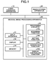
- FIG. 1 is a block diagram illustrating an exemplary configuration of a medical information processing system according to a first embodiment
- FIG. 2 is a block diagram illustrating an exemplary configuration of an X-ray diagnosis apparatus according to the first embodiment
- FIG. 3A is a drawing illustrating an example of image processing according to the first embodiment
- FIG. 3B is a drawing illustrating another example of the image processing according to the first embodiment
- FIG. 3C is a drawing illustrating yet another example of the image processing according to the first embodiment
- FIG. 3D is a drawing illustrating yet another example of the image processing according to the first embodiment
- FIG. 4 is a flowchart for explaining a flow in a series of processes performed by a medical image processing apparatus according to the first embodiment
- FIG. 5 is a flowchart for explaining a flow in a series of processes performed by a medical image processing apparatus according to a second embodiment.
- FIG. 6 is a block diagram illustrating an exemplary configuration of an X-ray diagnosis apparatus according to a fourth embodiment.
- a medical information processing system including a medical image processing apparatus and an X-ray diagnosis apparatus will be explained as an example.
- a medical information processing system 1 includes an X-ray diagnosis apparatus 10 , an image storing apparatus 20 , and a medical image processing apparatus 30 .
- FIG. 1 is a block diagram illustrating an exemplary configuration of the medical information processing system 1 according to the first embodiment. As illustrated in FIG. 1 , the X-ray diagnosis apparatus 10 , the image storing apparatus 20 , and the medical image processing apparatus 30 are connected to one another via a network.
- the X-ray diagnosis apparatus 10 is configured to acquire one or more X-ray images from a subject P.
- X-ray images processed as data may also be referred to as X-ray image data.
- the X-ray diagnosis apparatus 10 acquires a plurality of pieces of X-ray image data in a time series from the subject P and transmits the acquired plurality of pieces of X-ray image data to the image storing apparatus 20 and to the medical image processing apparatus 30 .
- a configuration of the X-ray diagnosis apparatus 10 will be explained later.
- the image storing apparatus 20 is configured to store therein a plurality of pieces of X-ray image data acquired by the X-ray diagnosis apparatus 10 .
- the image storing apparatus 20 is realized by using a computer device such as a server.
- the image storing apparatus 20 acquires the plurality of pieces of X-ray image data from the X-ray diagnosis apparatus 10 via the network and stores the acquired plurality of pieces of X-ray image data into a memory provided either inside or outside of the apparatus.
- the medical image processing apparatus 30 is configured to acquire a plurality of pieces of X-ray image data in a time series via a network and to perform various types of processes by using the acquired plurality of pieces of X-ray image data.
- the medical image processing apparatus 30 is realized by using a computer device such as a workstation.
- the medical image processing apparatus 30 acquires the plurality of pieces of X-ray image data in the time series acquired by the X-ray diagnosis apparatus 10 . Further, the medical image processing apparatus 30 performs image processing on the acquired plurality of pieces of X-ray image data. The image processing performed by the medical image processing apparatus 30 will be explained later.
- the medical image processing apparatus 30 includes an input interface 31 , a display 32 , a memory 33 , and processing circuitry 34 .
- the input interface 31 is realized by using a trackball, a switch, a button, a mouse, and/or a keyboard used for inputting various types of instructions and various types of settings, a touchpad used for performing an input operation by touching an operation surface thereof, a touch screen in which a display screen and a touch pad are integrally formed, a contactless input circuit using an optical sensor, an audio input circuit, and/or the like.
- the input interface 31 is configured to convert an input operation received from an operator into an electrical signal and to output the electrical signal to the processing circuitry 34 .
- the input interface 31 does not necessarily have to include one or more physical operation component parts such as a mouse and a keyboard.
- possible examples of the input interface 31 include electrical signal processing circuitry configured to receive an electrical signal corresponding to an input operation from an external input device provided separately from the medical image processing apparatus 30 and to output the electrical signal to the processing circuitry 34 .
- the display 32 is configured to display various types of information.
- the display 32 displays a Graphical User Interface (GUI) used for receiving an instruction from the operator and various types of image data.
- GUI Graphical User Interface
- the display 32 may be a liquid crystal display or a Cathode Ray Tube (CRT) display.
- the memory 33 is realized by using, for example, a semiconductor memory element such as a Random Access Memory (RAM), a flash memory, or the like, or a hard disk, an optical disk, or the like.
- the memory 33 is configured to store therein the plurality of pieces of X-ray image data in the time series acquired from the X-ray diagnosis apparatus 10 .
- the memory 33 stores therein one or more computer programs (hereinafter, “programs”) used by circuitry included in the medical image processing apparatus 30 for realizing the functions thereof.
- the processing circuitry 34 is configured to control operations of the entirety of the medical image processing apparatus 30 by executing an acquiring function 34 a , a setting function 34 b , a generating function 34 c , and a display controlling function 34 d.
- the processing circuitry 34 is configured to acquire the plurality of pieces of X-ray image data in the time series from the X-ray diagnosis apparatus 10 , by reading and executing a program corresponding to the acquiring function 34 a from the memory 33 . Further, for example, the processing circuitry 34 is configured to set the number of frames used as a unit during image processing that is performed for each of the groups made up of X-ray images in two or more frames, by reading and executing a program corresponding to the setting function 34 b from the memory 33 .
- the processing circuitry 34 is configured to generate an image in which the pixel value of each of the pixels expresses either the largest pixel value or the smallest pixel value among the corresponding pixels in the pieces of X-ray image data corresponding to the set number of frames, for each of the groups made up of X-ray images that correspond to the number of frames set by the setting function 34 b and are among the plurality of pieces of X-ray image data in the time series, by reading and executing a program corresponding to the generating function 34 c from the memory 33 .
- processing functions are stored in the memory 33 in the form of computer-executable programs.
- the processing circuitry 34 is a processor configured to realize the functions corresponding to the programs by reading and executing the programs from the memory 33 .
- the processing circuitry 34 that has read the programs has the functions corresponding to the read programs.
- FIG. 1 the example was explained in which the single processing circuit realizes the acquiring function 34 a , the setting function 34 b , the generating function 34 c , and the display controlling function 34 d .
- the processing circuitry 34 is structured by combining together a plurality of independent processors, so that the functions are realized as a result of the processors executing the programs.
- FIG. 2 is a block diagram illustrating an exemplary configuration of the X-ray diagnosis apparatus 10 according to the first embodiment.
- the X-ray diagnosis apparatus 10 includes an X-ray high-voltage device 101 , an X-ray tube 102 , a collimator 103 , a filter 104 , a tabletop 105 , a C-arm 106 , an X-ray detector 107 , a controlling device 106 , a memory 109 , a display 110 , an input interface 111 , and processing circuitry 112 .
- the X-ray high-voltage device 101 is configured to supply high voltage to the X-ray tube 102 under control of the processing circuitry 112 .
- the X-ray high-voltage device 101 includes: a high-voltage generating device that includes electric circuitry such as a transformer, a rectifier, and the like and is configured to generate the high voltage to be applied to the X-ray tube 102 ; and an X-ray controlling device configured to control the output voltage in accordance with the X-rays to be radiated by the X-ray tube 102 .
- the high-voltage generating device may be of a transformer type or an inverter type.
- the X-ray tube 102 is a vacuum tube including a negative pole (a filament) configured to generate thermo electrons and a positive pole (a target) configured to generate the X-rays in response to collisions of the thermo electrons.
- the X-ray tube 102 is configured to generate the X-rays by emitting the thermos electrons from the negative pole toward the positive pole, by using the high voltage supplied thereto from the X-ray high-voltage device 101 .
- the collimator (which may also be referred to as an X-ray limiting device) 103 includes, for example, four slidable limiting blades. By sliding the limiting blades, the collimator 103 is configured to narrow down the X-rays generated by the X-ray tube 102 and to arrange the X-rays to be radiated onto the subject P.
- the limiting blades are date-like members configured by using lead or the like and are disposed in the vicinity of an X-ray radiation opening of the X-ray tube 102 for the purpose of adjusting the radiation range of the X-rays.
- the filter 104 is configured to reduce soft X-ray components that are easily absorbed by the subject P and to reduce high-energy components that may degrade the contrast of X-ray image data, by changing the quality of passing X-rays with the material and/or the thickness thereof, for the purpose of reducing the radiation exposure amount for the subject P and improving the quality of the X-ray image data. Further, the filter 104 is configured to attenuate the X-rays so that the X-rays radiated from the X-ray tube 102 onto the subject P have a distribution determined in advance, by changing the radiation dose and the radiation range of the X-rays with the material, the thickness, and/or the position thereof.
- the tabletop 105 is a bed on which the subject P is placed and is arranged over a couch (not illustrated).
- the subject P is not included in the X-ray diagnosis apparatus 10 .
- the C-arm 106 is configured to hold the X-ray tube 102 , the collimator 103 , and the filter 104 so as to oppose the X-ray detector 107 , while the subject P is interposed therebetween.
- FIG. 2 illustrates an example in which the X-ray diagnosis apparatus 10 is of a single-plane type, possible embodiments are not limited to this example.
- the X-ray diagnosis apparatus 10 may be of a bi-plane type.
- the X-ray detector 107 is, for example, an X-ray Flat Panel Detector (FPD) including detecting elements arranged in a matrix formation.
- the X-ray detector 107 is configured to detect X-rays that were radiated from the X-ray tube 102 and have passed through the subject P and to output a detection signal corresponding to a detected X-ray amount to the processing circuitry 112 .
- the X-ray detector 107 may be an indirect-conversion type detector including a grid, a scintillator array, and an optical sensor array or may be a direct-conversion type detector including a semiconductor element configured to convert incident X-rays into an electrical signal.
- the controlling device 108 includes: a driving mechanism structured with a motor and an actuator or the like; and circuitry configured to control the driving mechanism. Under control of the processing circuitry 112 , the controlling device 108 is configured to control operations of the collimator 103 , the filter 104 , the tabletop 105 , the C-arm 106 , and the like. For example, the controlling device 108 is configured to control the radiation range of the X-rays to be radiated onto the subject P, by adjusting the opening degree of the limiting blades of the collimator 103 . Further, the controlling device 108 is configured to control the distribution of the radiation dose of the X-rays radiated onto the subject P by adjusting the position of the filter 104 . Further, for example, the controlling device 108 is configured to rotate and move the C-arm 106 and to move the tabletop 105 .
- the memory 109 is, for example, realized by using a semiconductor memory element such as a R a flash memory, or the like, or a hard disk, an optical disk, or the like.
- the memory 109 is configured to receive and store therein the X-ray image data acquired by the processing circuitry 112 .
- the memory 109 is configured to store therein programs corresponding to various types of functions that are read and executed by the processing circuitry 112 .
- the display 110 is configured to display various types of information.
- the display 110 is configured to display a GUI used for receiving instructions from an operator and various types of X-ray images.
- the display 110 may be a liquid crystal display or a CRT display.
- the input interface 111 is realized by using a trackball, a switch, a button, a mouse, and/or a keyboard used for inputting various types of instructions and various types of settings, a touchpad used for performing an input operation by touching an operation surface thereof, a touch screen in which a display screen and a touch pad are integrally formed, a contactless input circuit using an optical sensor, an audio input circuit, and/or the like.
- the input interface 111 is configured to convert an input operation received from an operator into an electrical signal and to output the electrical signal to the processing circuitry 112 .
- the input interface 111 does not necessarily have to include one or more physical operation component parts such as a mouse and a keyboard.
- possible examples of the input interface 111 include electrical signal processing circuitry configured to receive an electrical signal corresponding to an input operation from an external input device provided separately from the X-ray diagnosis apparatus 10 and to output the electrical signal to the processing circuitry 112 .
- the processing circuitry 112 is configured to control operations of the entirety of the X-ray diagnosis apparatus 10 by executing a controlling function 112 a , an acquiring function 112 b , and a display controlling function 112 c .
- the processing circuitry 112 is configured to control various types of functions of the processing circuitry 112 on the basis of the input operations received from the operator via the input interface 111 , by reading and executing a program corresponding to the controlling function 112 a from the memory 109 .
- the processing circuitry 112 is configured to acquire the X-ray image data, by reading and executing a program corresponding to the acquiring function 112 b from the memory 109 .
- the acquiring function 112 b is configured to control the radiation dose and to turn on and off the X-rays radiated onto the subject P, by controlling the X-ray high-voltage device 101 so as to adjust the voltage supplied to the X-ray tube 102 .
- the acquiring function 112 b is configured to control the radiation range of the X-rays radiated onto the subject. P, by controlling the controlling device 108 so as to adjust the opening degree of the limiting blades included in the collimator 103 .
- the acquiring function 112 b is configured to control the distribution of the radiation dose of the X-rays by controlling the controlling device 108 so as to adjust the position of the filter 104 . Further, the acquiring function 112 b is configured to control the rotation and the moving of the C-arm 106 as well as the moving of the tabletop 105 and the like, by controlling the controlling device 108 . Further, the acquiring function 112 b is configured to generate the X-ray image data on the basis of the detection signal received from the X-ray detector 107 and to store the generated X-ray image data into the memory 109 . In this situation, the acquiring function 112 b may also perform various types of image processing on the X-ray image data stored in the memory 109 . For example, the acquiring function 112 b may perform a noise reducing process, a scattered ray correcting process, and/or the like on the X-ray image data, by using image processing filter.
- processing circuitry 112 is configured to cause the display 110 to display the X-ray image data acquired by the acquiring function 112 b , by reading and executing a program corresponding to the display controlling function 112 c from the memory 109 .
- the display controlling function 112 c is configured to cause the display 110 to display the GUI used for receiving instructions from the operator.
- processing functions are stored in the memory 109 in the form of computer-executable programs.
- the processing circuitry 112 is a processor configured to realize the functions corresponding to the programs, by reading and executing the programs from the memory 109 .
- the processing circuitry 112 that has read the programs has the functions corresponding to the read programs.
- the single processing circuit i.e., the processing circuitry 112
- realizes the controlling function 112 a the acquiring function 112 b
- the display controlling function 112 c the processing circuitry 112 is structured by combining together a plurality of independent processors, so that the functions are realized as a result of the processors executing the programs.
- processor denotes, for example, a Central Processing Unit (CPU), a Graphics Processing Unit (GPU), or a circuit such as an Application Specific Integrated Circuit (ASIC) or a programmable logic device (e.g., a Simple Programmable Logic Device [SOLD], a Complex Programmable Logic Device [COLD], or a Field Programmable Gate Array [FPGA]).
- CPU Central Processing Unit
- GPU Graphics Processing Unit
- ASIC Application Specific Integrated Circuit
- programmable logic device e.g., a Simple Programmable Logic Device [SOLD], a Complex Programmable Logic Device [COLD], or a Field Programmable Gate Array [FPGA].
- SOLD Simple Programmable Logic Device
- COLD Complex Programmable Logic Device
- FPGA Field Programmable Gate Array
- the processors in the present embodiment do not each necessarily have to be structured as a single circuit. It is also acceptable to structure one processor by combining together a plurality of independent circuits so as to realize the functions thereof. Further, with reference to FIGS. 1 and 2 , the examples were explained in which the single memory (the memory 33 and the memory 109 ) stores therein the programs corresponding to the processing functions. However, another arrangement is also acceptable in which a plurality of memories 33 are provided in a distributed manner, so that the processing circuitry 34 reads a corresponding program from each of the individual memories 33 .
- yet another arrangement is also acceptable in which a plurality of memories 109 are provided in a distributed manner, so that the processing circuitry 112 reads a corresponding program from each of the individual memories 109 .
- the programs are directly incorporated in the circuits of the one or more processors. In that situation, the one or more processors realize the functions thereof by reading and executing the programs incorporated in the circuits thereof.
- the medical information processing system 1 including the medical image processing apparatus 30 and the X-ray diagnosis apparatus 10 has thus been explained.
- the medical image processing apparatus 30 in the medical information processing system 1 structured as described above is configured to improve visibility of the X-ray images with the processes performed by the processing circuitry 34 explained in detail below.
- processes performed by the medical image processing apparatus 30 according to the first embodiment will be explained in detail.
- the setting function 34 b sets the number of frames used as a unit during image processing. For example, by receiving an input operation indicating the number of frames via the input interface 31 , the setting function 34 b sets the number of frames.
- the setting function 34 b sets the number of frames.
- an example will be explained in which “3 frames” is set as the number of frames used as a unit during the image processing.
- the acquiring function 112 b included in the X-ray diagnosis apparatus 10 acquires a plurality of pieces of X-ray image data in a time series.
- the acquiring function 112 b at first causes X-rays in a pulse form to be radiated onto the subject P from the X-ray tube 102 .
- the X-ray detector 107 detects X-rays that have passed through the heart of the subject P and outputs a detection signal corresponding to the detected X-ray amount to the processing circuitry 112 .
- the acquiring function 112 b After that, the acquiring function 112 b generates X-ray image data on the basis of the detection signal received from the X-ray detector 107 and outputs the generated X-ray image data to the medical image processing apparatus 30 . Further, the acquiring function 112 b generates a piece of X-ray image data every time X-rays in a pulse form are radiated and sequentially outputs the generated pieces of X-ray image data to the medical image processing apparatus 30 .
- the acquiring function 34 a acquires the plurality of pieces of X-ray image data in the time series. For example, the acquiring function 34 a sequentially acquires the pieces of X-ray image data acquired by the acquiring function 112 b and stores the acquired pieces of X-ray image data into the memory 33 . For example, when the acquiring function 112 b acquires a piece of X-ray image data I 11 illustrated in FIG. 3A , the acquiring function 34 a acquires and stores, into the memory 33 , the piece of X-ray image data I 11 .
- FIG. 3A is a drawing illustrating the example of the image processing according to the first embodiment.
- the piece of X-ray image data I 11 X-ray image data in which the subject P is rendered while having no contrast agent injected in blood vessels.
- the piece of X-ray image data I 11 is X-ray image data acquired before a contrast agent is injected into the subject P.
- the pieces of X-ray image data I 12 and I 13 are each X-ray image data in which the subject P is rendered while having the contrast agent injected in the blood vessels.
- the pieces of X-ray image data I 12 and I 12 are each X-ray image data acquired by injecting the contrast agent in the radiation range of the X-rays or acquired after the contrast agent injected on the outside of the radiation range of the X-rays flows into the radiation range of the X-rays.
- the injection of the contrast agent may be performed by an injector (not illustrated) or may be performed by an operator.
- contrast agents include: positive contrast agents each having an X-ray attenuation coefficient larger than those of peripheral tissues of the subject P; and negative contrast agents each having an X-ray attenuation coefficient smaller than those of peripheral tissues of the subject P.
- the positive contrast agents are contrast agents of which the main component is iodine, barium sulfate, or the like.
- the negative contrast agents are, for example, gaseous contrast agents using carbon dioxide, oxygen, nitrogen, air, or the like.
- the contrast agent is carbon dioxide.
- the carbon dioxide injected in the blood vessels is rendered with pixel values larger (appear brighter) than the pixel values with which peripheral tissues are rendered. Further, the carbon dioxide injected in the blood vessels flows in the downstream direction along with the blood flow.
- the generating function 34 c generates a piece of image data in which the pixel value of each of the pixels expresses either the largest pixel value or the smallest pixel value among the corresponding pixels in the pieces of X-ray image data in the “3 frames”.
- the corresponding pixels may be, for example, pixels that are in mutually the same position (at mutually the same coordinates) in the pieces of X-ray image data.
- the generating function 34 c generates a piece of image data in which the pixel value of each of the pixels expresses either the largest pixel value or the smallest pixel value among the corresponding pixels in the pieces of X-ray image data I 11 , I 12 and I 13 .
- a piece of image data in which the pixel value of each of the pixels expresses the largest pixel values among the corresponding pixels in a plurality of pieces of X-ray image data will be referred to as a largest value image.
- a piece of image data in which the pixel value of each of the pixels expresses the smallest pixel values among the corresponding pixels in a plurality of pieces of X-ray image data will be referred to as a smallest value image.
- the generating function 34 c may generate both the largest value images and the smallest value images or may generate one selected from between the largest value images and the smallest value images.
- the generating function 34 c generates one selected from between the largest value images and the smallest value images in accordance with the type of the contrast agent being used.
- the generating function 34 c may acquire the type of the contrast agent being used by receiving an input operation from the operator or may acquire the type of the contrast agent being used from image taking conditions set for the subject P. Further, when the contrast agent is injected by using an injector, the generating function 34 c may acquire the type of the contrast agent being used, from contrast enhancement conditions set with the injector.
- the generating function 34 c generates a largest value image I 21 in which the pixel value of each of the pixels expresses the largest pixel value among the corresponding pixels in the pieces of X-ray image data I 11 , I 12 , and I 13 .
- the carbon dioxide is rendered with pixel values larger than the pixel values with which the peripheral tissues are rendered, the carbon dioxide rendered in at least one of the pieces of X-ray image data I 11 , I 12 , and I 13 is also rendered in the largest value image I 21 .
- Carbon dioxide in a blood vessel may be separated at the time of being injected or while flowing through the blood vessel and may not be in the form of a single bubble.
- the blood vessel which is supposed to be continuous, may be rendered as being divided in sections.
- the generating function 34 c is able to render the blood vessel as being continuous and to thus improve the visibility.
- the contrast of the carbon dioxide to the peripheral tissues may be low in the X-ray image data, in some situations. Even in those situations, by generating the largest value image I 21 , the generating function 34 c is able to emphasize the contrast of the carbon dioxide to the peripheral tissues and to thus improve the visibility.
- the display controlling function 34 d causes the display 32 to display the largest value image I 21 generated by the generating function 34 c . Further, the memory 33 stores therein the largest value image I 21 generated by the generating function 34 c . Alternatively, the generating function 34 c may output the generated largest value image I 21 to the image storing apparatus 20 . In that situation, the image storing apparatus 20 stores therein the largest value image I 21 generated by the generating function 34 c . In one example, after generating the largest value image I 21 , the generating function 34 c may delete the piece of X-ray image data I 11 stored in the memory 33 .
- FIG. 3B is a drawing illustrating another example of the image processing according to the first embodiment.
- the piece of X-ray image data I 14 is X-ray image data in which the subject P is rendered while having the contrast agent injected in the blood vessels.
- the generating function 34 c generates a largest value image for each of the groups made up of pieces of X-ray image data that correspond to the number of frames “3 frames” set by the setting function 34 b and are among the plurality of pieces of X-ray image data acquired by the acquiring function 34 a .
- the generating function 34 c generates a largest value image I 22 with respect to the pieces of X-ray image data in the “3 frames” including the new piece of X-ray image data I 14 and the pieces of X-ray image data I 12 and I 13 acquired immediately before the piece of X-ray image data I 14 .
- the display controlling function 34 d causes the display 32 to display the largest value image I 22 generated by the generating function 34 c .
- the display controlling function 34 d switches the display of the largest value image I 21 that has been displayed on the display 32 into display of the largest value image I 22 .
- the largest value image I 22 renders the carbon dioxide that has diffused farther downstream. Accordingly, by having the largest value images I 21 and I 22 displayed, the operator is able to visually recognize not only the shapes of the blood vessels, but also the manner in which the contrast agent diffuses in the blood vessels.
- the memory 33 stores therein the largest value image I 22 generated by the generating function 34 c .
- the generating function 34 c may output the generated largest value image I 22 to the image storing apparatus 20 .
- the image storing apparatus 20 stores therein the largest value image I 22 generated by the generating function 34 c .
- the generating function 34 c may delete the piece of X-ray image data I 12 stored in the memory 33 .
- FIG. 3C is a drawing illustrating yet another example of the image processing according to the first embodiment.
- the piece of X-ray image data I 15 is X-ray image data in which the subject F is rendered while having the contrast agent injected in the blood vessels.
- the generating function 34 c generates a largest value image for each of the groups made up of pieces of X-ray image data that correspond to the number of frames “3 frames” set by the setting function 34 b and are among the plurality of pieces of X-ray image data acquired by the acquiring function 34 a .
- the generating function 34 c generates a largest value image I 23 with respect to the pieces of X-ray image data in the “3 frames” including the new piece of X-ray image data I 15 and the pieces of X-ray image data I 13 and I 14 acquired immediately before the piece of X-ray image data I 15 .
- the display controlling function 34 d causes the display 32 to display the largest value image I 23 generated by the generating function 34 c .
- the display controlling function 34 d switches the display of the largest value image I 22 that has been displayed on the display 32 into display of the largest value image I 23 .
- the largest value image I 23 renders the carbon dioxide that has diffused farther downstream. Accordingly, by having the largest value images I 21 , I 22 , and I 23 displayed, the operator is able to visually recognize not only the shapes of the blood vessels, but also the manner in which the contrast agent diffuses in the blood vessels.
- the memory 33 stores therein the largest value image I 23 generated by the generating function 34 c .
- the generating function 34 c may output the generated largest value image I 23 to the image storing apparatus 20 .
- the image storing apparatus 20 stores therein the largest value image I 23 generated by the generating function 34 c .
- the generating function 34 c may delete the piece of X-ray image data I 13 stored in the memory 33 .
- FIG. 3D is a drawing illustrating yet another example of the image processing according to the first embodiment.
- the piece of X-ray image data I 16 is X-ray image data in which the subject P is rendered while having the contrast agent injected in the blood vessels.
- the generating function 34 c generates a largest value image for each of the groups made up of pieces of X-ray image data that correspond to the number of frames “3 frames” set by the setting function 34 b , and are among the plurality of pieces of X-ray image data acquired by the acquiring function 34 a .
- the generating function 34 c generates a largest value image I 24 with respect to the pieces of X-ray image data in the “3 frames” including the new piece of X-ray image data I 16 and the pieces of X-ray image data I 14 and I 15 acquired immediately before the piece of X-ray image data I 16 .
- the display controlling function 34 d causes the display 32 to display the largest value image I 24 generated by the generating function 34 c .
- the display controlling function 34 d switches the display of the largest value image I 23 that has been displayed on the display 32 into display of the largest value image I 24 .
- the largest value image I 24 has a region in which no carbon dioxide is rendered in such a part of the blood vessel that is positioned upstream. This region is a region into which the carbon dioxide had flowed in and from which substantially all of the carbon dioxide subsequently flowed out along with the blood flow.
- the operator is able to visually recognize not only the shapes of the blood vessels, but also the manner in which the contrast agent flows, from the time when the contrast agent flows into the blood vessels, to the time when the contrast agent flows out.
- the memory 33 stores therein the largest value image I 24 generated by the generating function 34 c .
- the generating function 34 c may output the generated largest value image I 24 to the image storing apparatus 20 .
- the image storing apparatus 20 stores therein the largest value image I 24 generated by the generating function 34 c .
- the generating function 34 c may delete the piece of X-ray image data I 14 stored in the memory 33 .
- the acquiring function 34 a is configured to sequentially acquire the pieces of X-ray image data acquired by the X-ray diagnosis apparatus 10 .
- the generating function 34 c is configured to sequentially generate the largest value images, for the groups each being made up of pieces of X-ray image data corresponding to “3 frames” and each including a newly-acquired piece of X-ray image data and the two pieces of X-ray image data acquired immediately before the newly-acquired piece of X-ray image data.
- the generating function 34 c is configured to generate the largest value images in parallel with at least one selected from between the acquisition of the pieces of X-ray image data performed by the X-ray diagnosis apparatus 10 and the acquisition of the pieces of X-ray image data performed by the acquiring function 34 a.
- the contrast agent is carbon dioxide as been explained above; however, the contrast agent may be a gaseous contrast agent other than carbon dioxide such as oxygen, nitrogen, air, or the like or may be a contrast agent of which the main component is iodine, barium sulfate, or the like.
- the contrast agent is a contrast agent of which the main component is iodine (hereinafter, simply “iodine”)
- the generating function 34 c generates a smallest value image for each of the groups made up of pieces of X-ray image data corresponding to the set number of frames.
- the generating function 34 c when the contrast agent is a gaseous contrast agent, the generating function 34 c generates a largest value image for each of groups made up of pieces of X-ray image data corresponding to the set number of frames. Further, when there is no particular restriction about the type or the amount of the contrast agent to be used, the generating function 34 c does not necessarily have to generate the largest value images or the smallest value images. For example, when the contrast agent is iodine, while there is no particular restriction about the amount to be used, the display controlling function 34 d causes the display to display X-ray images acquired by the acquiring function 34 a.
- FIG. 4 is a flowchart for explaining a flow in a series of processes performed by the medical image processing apparatus 30 according to the first embodiment.
- Steps S 104 and S 109 are steps corresponding to the acquiring function 34 a .
- Steps S 101 , S 102 , and S 103 are steps corresponding to the setting function 34 b .
- Steps S 105 , S 106 , and S 107 are steps corresponding to the generating function 34 c .
- Step S 108 is a step corresponding to the display controlling function 34 d.
- the processing circuitry 34 judges whether or not an input operation indicating the number of frames has been received (step S 101 ). When an input operation indicating the number of frames has been received (step Yes), the processing circuitry 34 sets the input number of frames (step S 102 ). On the contrary, when no input operation indicating the number of frames has been received (step S 101 : No), the processing circuitry 34 sets a pre-set value as the number of frames (step S 103 ).
- the processing circuitry 34 acquires a plurality of pieces of X-ray image data in a time series ( 104 ) and judges whether or not the contrast agent is a gaseous contrast agent (step S 105 ).
- the processing circuitry 34 generates a largest value image for each of the groups made up of pieces of X-ray image data corresponding to the set number of frames (step S 106 ).
- step S 105 when the contrast agent is not a gaseous contrast agent (step S 105 : No), the processing circuitry 34 generates a smallest value image for each of the groups made up of pieces of X-ray image data corresponding to the set number of frames (step S 107 ). After that, the processing circuitry 34 causes the display 32 to display the images generated at either step S 106 or step S 107 (step S 108 ).
- the processing circuitry 34 judges whether or not a new piece of X-ray image data is acquired (step S 109 ).
- step S 109 the processing circuitry 34 returns to step S 105 .
- step S 109 No
- the processing circuitry 34 ends the process.
- the acquiring function 34 a is configured to acquire the plurality of pieces of X-ray image data in the time series. Further, the setting function 34 b is configured to set the number of frames used as a unit during the image processing that is to be performed for each of the groups made up of pieces of X-ray image data in two or more frames.
- the generating function 34 c is configured to generate a piece of image data in which the pixel value of each of the pixels expresses either the largest pixel value or the smallest pixel value among the corresponding pixels in the pieces of X-ray image data corresponding to the set number of frames.
- the medical image processing apparatus 30 is able to improve the visibility by complementing the separation of the contrast agent in the blood vessels and emphasizing the contrast.
- X-ray image data is acquired by using iodine in an amount smaller than normal.
- the medical image processing apparatus 30 is able to improve the visibility by emphasizing the contrast.
- the example is explained in which the number of frames used as a unit during the image processing is set by receiving the input operation indicating the number of frames.
- the number of frames is set on the basis of a frame time period (hereinafter, “frame period”) and a framerate.
- the medical image processing apparatus 30 has a configuration similar to that of the medical image processing apparatus 30 illustrated in FIG. 1 , while a part of the processes performed by the setting function 34 b is different. Thus, some of the constituent elements that are the same as those explained in the first embodiment will be referred to by using the same reference characters as those in FIG. 1 , and explanations thereof will be omitted.
- the setting function 34 b is configured to set a frame period.
- the frame period is a time period used as a unit during image processing.
- the generating function 34 c performs the image processing for each of the groups made up of pieces of X-ray image data within the set frame period.
- the setting function 34 b may set the frame period by receiving an input operation indicating the frame period or may set the frame period to a pre-set value. In the following sections, an example will be explained in which the frame period is set to “2 seconds”.
- the setting function 34 b acquires a framerate.
- the framerate denotes the number of pieces of X-ray image data acquired per unit time period.
- the setting function 34 b acquires an X-ray radiation rate (the number of times the X-ray pulse is radiated per unit time period), as the framerate.
- the setting function 34 b may set the X-ray radiation rate by receiving an input operation from the operator, may acquire the X-ray radiation rate from image taking conditions set for the subject P, or may set the X-ray radiation rate to a radiation rate pre-set value.
- the setting function 34 b sets the number of frames on the basis of the frame period and the framerate. For example, the setting function 34 b sets the number of frames by multiplying the frame period by the framerate. For example, when the framerate is “3 frames per second (fps)”, the setting function 34 b sets the number of frames “6 frames” by multiplying the frame period “2 seconds” by the framerate “3 fps”.
- the generating function 34 c generates either a largest value image or a smallest value image for each of the groups made up of X-ray images corresponding to the number of frames “6 frames” (i.e., the frame period “2 seconds”).
- the framerate may not be constant in some situations.
- the plurality of pieces of X-ray image data in the time series acquired by the acquiring function 34 a may include two or more pieces of X-ray image data acquired at a framerate of “3 fps” and two or more pieces of X-ray image data acquired at a framerate of “6 fps”.
- the setting function 34 b sets the number of frames for each piece of X-ray image data, on the basis of the frame period “2 seconds” and the framerates.
- the setting function 34 b sets “6 frames” as the number of frames.
- the setting function 34 b sets “12 frames” as the number of frames.
- the generating function 34 c changes the number of frames in accordance with the framerates, while having the frame period fixed.
- FIG. 5 is a flowchart for explaining a flow in a series of processes performed by the medical image processing apparatus 30 according to the second embodiment.
- Steps S 204 and S 210 are steps corresponding to the acquiring function 34 a .
- Steps S 201 , S 202 , S 203 , S 205 , and S 211 are steps corresponding to the setting function 34 b .
- Steps S 206 , S 207 , and S 208 are steps corresponding to the generating function 34 c .
- Step S 209 is a step corresponding to the display controlling function 34 d.
- the processing circuitry 34 judges whether or not an input operation indicating a frame period has been received (step S 201 ).
- step S 201 Yes
- the processing circuitry 34 sets the input frame period (step S 202 ).
- step S 203 the processing circuitry 34 sets a pre-set value as the frame period (step S 203 ).
- the processing circuitry 34 acquires a plurality of pieces of X-ray image data in a time series (step S 204 ). Further, the processing circuitry 34 sets the number of frames, on the basis of the set frame period and the framerate of the acquired plurality of pieces of X-ray image data (step S 205 ). Further, the processing circuitry 34 judges whether or not the contrast agent is a gaseous contrast agent (step S 206 ). When the contrast agent is a gaseous contrast agent (step S 206 : Yes), the processing circuitry 34 generates a largest value image for each of the groups made up of pieces of X-ray image data corresponding to the set number of frames (step S 207 ). On the contrary, when the contrast agent.
- step S 206 the processing circuitry 34 generates a smallest value image for each of the groups made up of pieces of X-ray image data corresponding to the set number of frames (step S 208 ). After that, the processing circuitry 34 causes the display 32 to display the images generated at either step S 207 or step S 208 (step S 209 ).
- the processing circuitry 34 judges whether or not a new piece of X-ray image data is acquired (step S 210 ).
- step S 210 Yes
- the processing circuitry 34 judges whether or not the framerate has been changed (step S 211 ).
- the processing circuitry 34 returns to step S 205 where the processing circuitry 34 sets the number of frames, on the basis of the frame period and the post-change framerate.
- step S 211 No
- the processing circuitry 34 returns to step S 206 .
- the processing circuitry 34 ends the process.
- the setting function 34 b is configured to set the frame period and to set the number of frames on the basis of the set frame period and the framerate of the plurality of pieces of X-ray image data.
- the span in which the contrast agent is rendered in the largest value images or the smallest value images would change, as a result of the change in the framerate.
- the frame period was changed in accordance with the framerate while having the number of frames fixed, the frame period would be shortened due to an increase in the framerate, and the span in which the contrast agent is rendered in the largest value images or the smallest value images would become smaller.
- the medical image processing apparatus 30 changes the number of frames in accordance with the framerate while having the frame period fixed, it is possible, even when the framerate is changed, to prevent the span in which the contrast agent is rendered from drastically changing, in the largest value images or the smallest value images.
- the medical image processing apparatus 30 according to the third embodiment has a configuration similar to that of the medical image processing apparatus 30 illustrated in FIG. 1 , while a part of the processes performed by the setting function 34 b is different.
- some of the constituent elements that are the same as those explained in the first embodiment will be referred to by using the same reference characters as those in FIG. 1 , and explanations thereof will be omitted.
- the setting function 34 b may be configured to set the number of frames in accordance with the region of the subject. P rendered in the plurality of pieces of X-ray image data. For example, at first, the setting function 34 b acquires information about a target region set as an image taking condition as the region of the subject P rendered in the plurality of pieces of X-ray image data. Subsequently, the setting function 34 b acquires a table defining a correspondence relationship between regions and numbers of frames. The table may be, for example, generated in advance before the setting function 34 b sets the number of frames and be stored in the memory 33 .
- the setting function 34 b sets the number of frames kept in correspondence with the region of the subject P rendered in the plurality of pieces of X-ray image data, as the number of frames used as a unit during the image processing.
- the table may define a correspondence relationship between regions and frame periods.
- the setting function 34 b may be configured to evaluate the degree of movements of the region of the subject P rendered in the plurality of pieces of X-ray image data and to set the number of frames in accordance with the evaluated degree of the movements.
- the setting function 34 b acquires two or more pieces of X-ray image data in which the subject P is rendered while having no contrast agent injected in the blood vessels, from among the plurality of pieces of X-ray image data acquired by the acquiring function 34 a .
- the pieces of X-ray image data in which the subject P is rendered while having no contrast agent injected in the blood vessels are, for example, pieces of X-ray image data such as the piece of X-ray image data I 11 acquired before a contrast agent is injected into the subject P.
- the setting function 34 b calculates, for each of the combinations made up of pieces of X-ray image data included in the acquired plurality of pieces of X-ray image data, a sum of values each acquired by squaring the difference in the pixel values between the corresponding pixels.
- the sum calculated by the setting function 34 b expresses the degree of changes in the pixel values caused by movements of the region of the subject P. For this reason, by using the calculated sum values, the setting function 34 b is able to evaluate the degree of the movements of the region of the subject rendered in the plurality of nieces of X-ray image data.
- the setting function 34 b when more than one sum value is calculated, the setting function 34 b is able to evaluate the degree of the movement a of the region of the subject P rendered in the plurality of pieces of X-ray image data, by using an average value or a mean value of the calculated sum values. Further, in accordance with the evaluated degree of the movements, the setting function 34 b sets the number of frames. For example, the setting function 34 b sets the number of frames in such a manner that the larger the movements are, the smaller the number of frames is.
- the setting function 34 b is configured to set the number of frames in accordance with the region of the subject P or to set the number of frames in accordance with the evaluated degree of the movements, it is possible to alleviate distortions of the shapes of the blood vessels rendered in the largest value images.
- the example is explained in which the generating function 34 c generates either the largest value images or the smallest value images, in parallel with at least one selected from between the acquisition of the pieces of X-ray image data performed by the X-ray diagnosis apparatus 10 and the acquisition of the pieces of X-ray image data performed by the acquiring function 34 a .
- the example is explained in which the generating function 34 c generates either the largest value images or the smallest value images in a real-time manner.
- possible embodiments are not limited to this example.
- the acquiring function 34 a acquires a plurality of pieces of X-ray image data in a time series including the pieces of X-ray image data I 11 , I 12 , I 13 , I 14 , I 15 , and I 16 illustrated in FIG. 3D and stores the acquired pieces of X-ray image data into the memory 33 .
- the setting function 34 b sets the number of frames used as a unit during image processing. In this situation, the setting function 34 b may set the number of frames for each piece of X-ray image data.
- the generating function 34 c reads the plurality of pieces of X-ray image data from the memory 33 and further generates either a largest value image or a smallest value image for each of the groups made up of pieces of X-ray image data that correspond to the set number of frames and are among the read plurality of pieces of X-ray image data.
- the generating function 34 c reads the pieces of X-ray image data I 11 , I 12 , I 13 , I 14 , I 15 , and I 16 from the memory 33 and further generates the largest value images I 21 , I 22 , I 23 , and I 24 , for groups each made up of pieces of X-ray image data corresponding to “3 frames”.
- the generating function 34 c may perform image processing on Digital Subtraction Angiography (DSA) image data.
- DSA image data is X-ray image data generated by calculating the difference in pieces of X-ray image data between before and after the injection of a contrast agent into the subject F, so that the blood vessels of which the contrast is enhanced by the contrast agent are selectively rendered.
- a piece of X-ray image data acquired by using X-rays while a contrast agent is injected in the subject P may alternatively be referred to as a contrast image.
- a piece of X-ray image data acquired by using X-rays while no contrast agent is injected in the subject P may alternatively be referred to as a mask image.
- the DSA image data is image data acquired by subtracting the mask image from the contrast image.
- the acquiring function 34 a is configured to acquire a plurality of pieces of DSA image data in a time series acquired by the acquiring function 112 b .
- the generating function 34 c is configured to generate either a largest value image or a smallest value image for each of the groups made up of pieces of DSA image data corresponding to the set number of frames.
- the acquiring function 34 a is configured to acquire the plurality of pieces of X-ray image data in the time series acquired by the acquiring function 112 b .
- the generating function 34 c is configured to generate a plurality of pieces of DSA image data in a time series by subtracting a piece of X-ray image data rendering the subject P having no contrast agent injected in the blood vessels, from each of the pieces of X-ray image data which are among the plurality of pieces of X-ray image data and in which the subject P is rendered while having a contrast agent injected in the blood vessels.
- the generating function 34 c is configured to generate either a largest value image or a smallest value image for each of the groups made up of pieces of DSA image data corresponding to the set number of frames.
- the generating function 34 c may be configured to perform an image processing on pieces of X-ray image data resulting from a motion correcting process.
- the motion correcting process is, for example, a process to correct motion in the images caused by the pulsation, the respiration, body movements, and the like of the subject P.
- the acquiring function 34 a acquires a plurality of pieces of X-ray image data in a time series acquired by the acquiring function 112 b .
- the generating function 34 c extracts a feature point from each of the plurality of pieces of X-ray image data and further corrects motion in the pieces of X-ray image data so as to align the positions of the feature point among the images.
- examples of the feature point include a marker attached to a medical device inserted in the patient and a predetermined structure of a medical device.
- the generating function 34 c extracts, as the feature point, a marker attached to the stent, a stent strut having a mesh structure, a marker attached to a catheter or a guide wire used for inserting the stent into the blood vessel, or the like and further corrects the motion in each of the plurality of pieces of X-ray image data so as to align the positions of the feature point among the images.
- the feature point include a structure (e.g., a bone or a soft tissue) of the subject P.
- the generating function 34 c may correct the motion in each of the plurality of pieces of X-ray image data, in synchronization with the cycle of the pulsation or the respiration of the subject P. Further, the generating function 34 c generates either a largest value image or a smallest value image for each of the groups made up of the set number of frames, on the basis of the pieces of X-ray image data resulting from the motion correcting process.
- the acquiring function 34 a may be configured to acquire a plurality of pieces of X-ray image data in a time series resulting from the motion correcting process and having been acquired by the acquiring function 112 b
- the generating function 34 c is configured to generate either a largest value image or a smallest value image for each of the groups made up of the set number of frames, on the basis of the pieces of X-ray image data resulting from the motion correcting process.
- the example is explained in which the acquiring function 34 a acquires the plurality of pieces of X-ray image data in the time series from the X-ray diagnosis apparatus 10 .
- the acquiring function 34 a may acquire a plurality of pieces of X-ray image data that are transmitted from the X-ray diagnosis apparatus 10 to the image storing apparatus 20 and are stored in the image storing apparatus 20 .
- the processing circuitry 34 in the medical image processing apparatus 30 includes the acquiring function 34 a , the setting function 34 b , and the generating function 34 c .
- the processing circuitry 112 in the X-ray diagnosis apparatus 10 may include functions corresponding to the acquiring function 34 a , the setting function 34 b , and the generating function 34 c.
- the processing circuitry 112 in the X-ray diagnosis apparatus 10 may further include a setting function 112 d corresponding to the setting function 34 b and a generating function 112 e corresponding to the generating function 34 c as illustrated in FIG. 6 .
- FIG. 6 is a block diagram illustrating an exemplary configuration of the X-ray diagnosis apparatus 10 according to a fourth embodiment.
- the acquiring function 112 b is configured to acquire a plurality of pieces of X-ray image data in a time series.
- the setting function 112 d is configured to set the number of frames used as a unit during image processing performed by the generating function 112 e .
- the generating function 112 e is configured to generate either a largest value image or a smallest value image.
- the display controlling function 112 c is configured to cause the display 110 to display either the largest value images or the smallest value images generated by the generating function 112 e.
- the constituent elements of the apparatuses and the devices according to the above embodiments are based on functional concepts. Thus, it is not necessary to physically configure the constituent elements as indicated in the drawings. In other words, the specific modes of distribution and integration of the apparatuses and the devices are not limited to those illustrated in the drawings. It is acceptable to functionally or physically distribute or integrate all or a part of the apparatuses and the devices in any arbitrary unit, depending on various loads and the status of use. Further, all or an arbitrary part of the processing functions performed by the apparatuses and the devices may be realized by a CPU and a program that is analyzed and executed by the CPU or may be realized as hardware using wired logic.
- the medical image processing methods explained in the above embodiments may be realized by causing a computer such as a personal computer or a workstation to execute a medical image processing program prepared in advance.
- the medical image processing program may be distributed via a network such as the Internet.
- the medical image processing program may be recorded on a computer-readable non-transitory recording medium such as a hard disk, a Flexible Disk (FD), a Compact Disk Read-Only Memory (CD-ROM), a Magneto-Optical (MO) disk, a Digital Versatile Disk (DVD), or the like, so as to be executed as being read from the recording medium by a computer.
- FD Flexible Disk
- CD-ROM Compact Disk Read-Only Memory
- MO Magneto-Optical
- DVD Digital Versatile Disk
Landscapes
- Health & Medical Sciences (AREA)
- Life Sciences & Earth Sciences (AREA)
- Engineering & Computer Science (AREA)
- Medical Informatics (AREA)
- Public Health (AREA)
- Physics & Mathematics (AREA)
- General Health & Medical Sciences (AREA)
- Pathology (AREA)
- Biomedical Technology (AREA)
- Nuclear Medicine, Radiotherapy & Molecular Imaging (AREA)
- Heart & Thoracic Surgery (AREA)
- Veterinary Medicine (AREA)
- Animal Behavior & Ethology (AREA)
- Surgery (AREA)
- Molecular Biology (AREA)
- Biophysics (AREA)
- High Energy & Nuclear Physics (AREA)
- Radiology & Medical Imaging (AREA)
- Optics & Photonics (AREA)
- Computer Vision & Pattern Recognition (AREA)
- Physiology (AREA)
- Theoretical Computer Science (AREA)
- General Physics & Mathematics (AREA)
- Databases & Information Systems (AREA)
- Primary Health Care (AREA)
- Data Mining & Analysis (AREA)
- Epidemiology (AREA)
- Vascular Medicine (AREA)
- Dentistry (AREA)
- Oral & Maxillofacial Surgery (AREA)
- Apparatus For Radiation Diagnosis (AREA)
Abstract
Description
Claims (20)
Applications Claiming Priority (4)
| Application Number | Priority Date | Filing Date | Title |
|---|---|---|---|
| JP2018041078 | 2018-03-07 | ||
| JP2018-041078 | 2018-03-07 | ||
| JP2019039766A JP7423188B2 (en) | 2018-03-07 | 2019-03-05 | Medical image processing equipment and X-ray diagnostic equipment |
| JP2019-039766 | 2019-03-05 |
Publications (2)
| Publication Number | Publication Date |
|---|---|
| US20190274651A1 US20190274651A1 (en) | 2019-09-12 |
| US10863961B2 true US10863961B2 (en) | 2020-12-15 |
Family
ID=67842893
Family Applications (1)
| Application Number | Title | Priority Date | Filing Date |
|---|---|---|---|
| US16/294,961 Active 2039-06-21 US10863961B2 (en) | 2018-03-07 | 2019-03-07 | Medical image processing apparatus and X-ray diagnosis apparatus |
Country Status (1)
| Country | Link |
|---|---|
| US (1) | US10863961B2 (en) |
Families Citing this family (3)
| Publication number | Priority date | Publication date | Assignee | Title |
|---|---|---|---|---|
| CN110072457A (en) * | 2016-12-15 | 2019-07-30 | 皇家飞利浦有限公司 | Vascular structure is visualized |
| JP7442976B2 (en) * | 2019-04-10 | 2024-03-05 | 株式会社島津製作所 | X-ray imaging device |
| JP7571519B2 (en) * | 2020-12-16 | 2024-10-23 | 株式会社島津製作所 | X-ray fluoroscopic imaging device and X-ray image processing method |
Citations (7)
| Publication number | Priority date | Publication date | Assignee | Title |
|---|---|---|---|---|
| US20030229285A1 (en) | 2002-06-11 | 2003-12-11 | Simpson David Hope | Ultrasonic diagnostic micro-vascular imaging |
| US20070195932A1 (en) | 2006-02-20 | 2007-08-23 | Nakaura Takeshi | X-ray diagnostic apparatus, image processing apparatus, and program |
| US20080262354A1 (en) | 2006-01-10 | 2008-10-23 | Tetsuya Yoshida | Ultrasonic diagnostic apparatus and method of generating ultrasonic image |
| JP2010279594A (en) | 2009-06-05 | 2010-12-16 | Toshiba Corp | X-ray diagnostic imaging equipment |
| JP2011104055A (en) | 2009-11-16 | 2011-06-02 | Toshiba Corp | X-ray diagnostic apparatus |
| JP4945605B2 (en) | 2009-07-21 | 2012-06-06 | 株式会社東芝 | Ultrasonic diagnostic equipment |
| US20150374323A1 (en) * | 2014-06-26 | 2015-12-31 | Kabushiki Kaisha Toshiba | X-ray diagnosis apparatus |
-
2019
- 2019-03-07 US US16/294,961 patent/US10863961B2/en active Active
Patent Citations (10)
| Publication number | Priority date | Publication date | Assignee | Title |
|---|---|---|---|---|
| US20030229285A1 (en) | 2002-06-11 | 2003-12-11 | Simpson David Hope | Ultrasonic diagnostic micro-vascular imaging |
| JP2005528949A (en) | 2002-06-11 | 2005-09-29 | コーニンクレッカ フィリップス エレクトロニクス エヌ ヴィ | Ultrasound diagnostic microvascular imaging |
| US20080262354A1 (en) | 2006-01-10 | 2008-10-23 | Tetsuya Yoshida | Ultrasonic diagnostic apparatus and method of generating ultrasonic image |
| JP5323275B2 (en) | 2006-01-10 | 2013-10-23 | 株式会社東芝 | Ultrasonic diagnostic apparatus and control program for ultrasonic diagnostic apparatus |
| US20070195932A1 (en) | 2006-02-20 | 2007-08-23 | Nakaura Takeshi | X-ray diagnostic apparatus, image processing apparatus, and program |
| JP2007215925A (en) | 2006-02-20 | 2007-08-30 | Takeshi Nakaura | X-ray diagnostic apparatus, image processing apparatus, and program |
| JP2010279594A (en) | 2009-06-05 | 2010-12-16 | Toshiba Corp | X-ray diagnostic imaging equipment |
| JP4945605B2 (en) | 2009-07-21 | 2012-06-06 | 株式会社東芝 | Ultrasonic diagnostic equipment |
| JP2011104055A (en) | 2009-11-16 | 2011-06-02 | Toshiba Corp | X-ray diagnostic apparatus |
| US20150374323A1 (en) * | 2014-06-26 | 2015-12-31 | Kabushiki Kaisha Toshiba | X-ray diagnosis apparatus |
Also Published As
| Publication number | Publication date |
|---|---|
| US20190274651A1 (en) | 2019-09-12 |
Similar Documents
| Publication | Publication Date | Title |
|---|---|---|
| US11341638B2 (en) | Medical image diagnostic system and method for generating trained model | |
| US10575809B2 (en) | X-ray diagnosis apparatus | |
| US11051778B2 (en) | X-ray fluoroscopic imaging apparatus | |
| US10080532B2 (en) | X-ray diagnostic apparatus | |
| US10863961B2 (en) | Medical image processing apparatus and X-ray diagnosis apparatus | |
| US10229515B2 (en) | Radiation diagnosis apparatus | |
| US11096646B2 (en) | X-ray imaging apparatus | |
| US11151726B2 (en) | Medical image processing apparatus, X-ray diagnostic apparatus, and medical image processing method | |
| US12064279B2 (en) | Device and method for editing a panoramic radiography image | |
| JP6879376B2 (en) | Radiation imaging device | |
| US20250064420A1 (en) | Medical image processing apparatus, recording medium, and system | |
| JP2018042627A (en) | Medical image diagnostic apparatus and medical image processing apparatus | |
| JP7167564B2 (en) | Radiographic device and method of operating the radiographic device | |
| US11344271B2 (en) | X-ray diagnostic apparatus and X-ray tube holding device | |
| US20210321966A1 (en) | X-ray diagnostic apparatus and medical-information processing apparatus | |
| US8761339B2 (en) | Method and apparatus for image diagnosis | |
| US11179125B2 (en) | Medical image processing apparatus, x-ray diagnosis apparatus, and medical image processing method | |
| US20230056033A1 (en) | X-ray diagnosis apparatus, medical image processing apparatus, and storage medium | |
| JP2021062065A (en) | Medical image processing device and x-ray diagnostic device | |
| JP2020096702A (en) | Medical image processing apparatus, X-ray diagnostic apparatus, and medical image processing program | |
| US11464474B2 (en) | Medical image processing apparatus, X-ray diagnostic apparatus, and medical image processing method | |
| US20230284992A1 (en) | X-ray diagnosis apparatus and control method of the same | |
| JP7423188B2 (en) | Medical image processing equipment and X-ray diagnostic equipment | |
| JP6956554B2 (en) | X-ray diagnostic equipment and image processing program | |
| CN110742629A (en) | Display method of blood vessel subtraction image and graphical user interface device |
Legal Events
| Date | Code | Title | Description |
|---|---|---|---|
| FEPP | Fee payment procedure |
Free format text: ENTITY STATUS SET TO UNDISCOUNTED (ORIGINAL EVENT CODE: BIG.); ENTITY STATUS OF PATENT OWNER: LARGE ENTITY |
|
| AS | Assignment |
Owner name: CANON MEDICAL SYSTEMS CORPORATION, JAPAN Free format text: ASSIGNMENT OF ASSIGNORS INTEREST;ASSIGNOR:OHASHI, SHUMPEI;REEL/FRAME:048776/0443 Effective date: 20190306 |
|
| STPP | Information on status: patent application and granting procedure in general |
Free format text: DOCKETED NEW CASE - READY FOR EXAMINATION |
|
| STPP | Information on status: patent application and granting procedure in general |
Free format text: NOTICE OF ALLOWANCE MAILED -- APPLICATION RECEIVED IN OFFICE OF PUBLICATIONS |
|
| STPP | Information on status: patent application and granting procedure in general |
Free format text: PUBLICATIONS -- ISSUE FEE PAYMENT RECEIVED |
|
| STCF | Information on status: patent grant |
Free format text: PATENTED CASE |
|
| MAFP | Maintenance fee payment |
Free format text: PAYMENT OF MAINTENANCE FEE, 4TH YEAR, LARGE ENTITY (ORIGINAL EVENT CODE: M1551); ENTITY STATUS OF PATENT OWNER: LARGE ENTITY Year of fee payment: 4 |