US10862507B2 - Variable-sized symbol entropy-based data compression - Google Patents
Variable-sized symbol entropy-based data compression Download PDFInfo
- Publication number
- US10862507B2 US10862507B2 US16/087,630 US201716087630A US10862507B2 US 10862507 B2 US10862507 B2 US 10862507B2 US 201716087630 A US201716087630 A US 201716087630A US 10862507 B2 US10862507 B2 US 10862507B2
- Authority
- US
- United States
- Prior art keywords
- symbol
- data
- symbols
- size
- collection
- Prior art date
- Legal status (The legal status is an assumption and is not a legal conclusion. Google has not performed a legal analysis and makes no representation as to the accuracy of the status listed.)
- Active, expires
Links
- 238000013144 data compression Methods 0.000 title claims abstract description 62
- 238000000034 method Methods 0.000 claims abstract description 100
- 230000006837 decompression Effects 0.000 claims abstract description 32
- 230000015654 memory Effects 0.000 claims description 120
- 238000004891 communication Methods 0.000 claims description 38
- 239000000872 buffer Substances 0.000 claims description 21
- 238000012545 processing Methods 0.000 claims description 15
- 238000005070 sampling Methods 0.000 claims description 12
- 238000004590 computer program Methods 0.000 claims description 6
- 238000003860 storage Methods 0.000 claims description 6
- 230000014759 maintenance of location Effects 0.000 claims description 2
- 230000008569 process Effects 0.000 description 40
- 238000007906 compression Methods 0.000 description 20
- 230000006835 compression Effects 0.000 description 17
- 239000011159 matrix material Substances 0.000 description 8
- 230000007246 mechanism Effects 0.000 description 8
- 238000012546 transfer Methods 0.000 description 8
- 238000005516 engineering process Methods 0.000 description 5
- 230000000694 effects Effects 0.000 description 3
- 230000008520 organization Effects 0.000 description 3
- 238000012360 testing method Methods 0.000 description 3
- 238000013500 data storage Methods 0.000 description 2
- 230000006870 function Effects 0.000 description 2
- 238000007429 general method Methods 0.000 description 2
- 238000013507 mapping Methods 0.000 description 2
- 238000005457 optimization Methods 0.000 description 2
- 238000013459 approach Methods 0.000 description 1
- 230000001174 ascending effect Effects 0.000 description 1
- 238000010276 construction Methods 0.000 description 1
- 230000001419 dependent effect Effects 0.000 description 1
- 238000013461 design Methods 0.000 description 1
- 238000010586 diagram Methods 0.000 description 1
- 238000005265 energy consumption Methods 0.000 description 1
- 230000000873 masking effect Effects 0.000 description 1
- 239000000463 material Substances 0.000 description 1
- 229910052710 silicon Inorganic materials 0.000 description 1
- 239000010703 silicon Substances 0.000 description 1
Images


Classifications
-
- H—ELECTRICITY
- H03—ELECTRONIC CIRCUITRY
- H03M—CODING; DECODING; CODE CONVERSION IN GENERAL
- H03M7/00—Conversion of a code where information is represented by a given sequence or number of digits to a code where the same, similar or subset of information is represented by a different sequence or number of digits
- H03M7/30—Compression; Expansion; Suppression of unnecessary data, e.g. redundancy reduction
- H03M7/3084—Compression; Expansion; Suppression of unnecessary data, e.g. redundancy reduction using adaptive string matching, e.g. the Lempel-Ziv method
- H03M7/3091—Data deduplication
- H03M7/3095—Data deduplication using variable length segments
-
- H—ELECTRICITY
- H03—ELECTRONIC CIRCUITRY
- H03M—CODING; DECODING; CODE CONVERSION IN GENERAL
- H03M7/00—Conversion of a code where information is represented by a given sequence or number of digits to a code where the same, similar or subset of information is represented by a different sequence or number of digits
- H03M7/30—Compression; Expansion; Suppression of unnecessary data, e.g. redundancy reduction
- H03M7/40—Conversion to or from variable length codes, e.g. Shannon-Fano code, Huffman code, Morse code
- H03M7/4093—Variable length to variable length coding
-
- H—ELECTRICITY
- H03—ELECTRONIC CIRCUITRY
- H03M—CODING; DECODING; CODE CONVERSION IN GENERAL
- H03M7/00—Conversion of a code where information is represented by a given sequence or number of digits to a code where the same, similar or subset of information is represented by a different sequence or number of digits
- H03M7/30—Compression; Expansion; Suppression of unnecessary data, e.g. redundancy reduction
- H03M7/40—Conversion to or from variable length codes, e.g. Shannon-Fano code, Huffman code, Morse code
- H03M7/4031—Fixed length to variable length coding
-
- H—ELECTRICITY
- H03—ELECTRONIC CIRCUITRY
- H03M—CODING; DECODING; CODE CONVERSION IN GENERAL
- H03M7/00—Conversion of a code where information is represented by a given sequence or number of digits to a code where the same, similar or subset of information is represented by a different sequence or number of digits
- H03M7/30—Compression; Expansion; Suppression of unnecessary data, e.g. redundancy reduction
- H03M7/3084—Compression; Expansion; Suppression of unnecessary data, e.g. redundancy reduction using adaptive string matching, e.g. the Lempel-Ziv method
- H03M7/3091—Data deduplication
Definitions
- This invention generally relates to the field of data compression, and more particularly to data compression in data communications devices and data memories in electronic computers. Even more specifically, the invention pertains to methods, devices and systems configured to sample, encode, compress, and decompress, respectively, symbols of variable size using entropy-based data compression principles.
- Data compression is a general technique to store and transfer data more efficiently by coding frequent collections of data more efficiently than less frequent collections of data. It is of interest to generally store and transfer data more efficiently for a number of reasons. In communications systems, say those building up the Internet, that potentially can connect all physical devices of interest to be globally accessible, it is of interest to transfer data more efficiently, say K times, as it then can be transferred potentially K times faster, using potentially K times less communication capacity and with potentially K times less energy expenditure.
- a microprocessor chip there is a limited number of transistors and the size of the cache memories integrated on said chips is constrained by such resource limitation.
- the size and weight of a smartphone, a tablet, a lap/desktop or a set-top box are limited as a larger or heavier smartphone, tablet, a lap/desktop or a set-top box could be of less value for an end user; hence potentially lowering the market value of such products.
- more memory capacity can potentially increase the market value of the product as more memory capacity can result in higher performance and hence better utility of the product.
- data compression can potentially increase the performance, increase the communication capacity, lower the energy expenditure or lower the cost and area consumed by memory. Therefore, data compression has a broad utility in a wide range of computerized products beyond those mentioned here.
- Data compression is a well-studied area. Methods known from prior art fall into lossless and lossy data compression methods. Whereas lossless data compression methods compress data without loss of information, lossy data compression methods trade a higher compression for less accuracy of the data. This is acceptable in some application domains such as in media compression; for example, a human user can accept some loss of information in for example images and audio. As lossy data compression methods, in general, do not resurrect data exactly, they, in general, compress data more efficiently than lossless compression methods. However, in some use cases of data compression, lossy compression methods are inadequate. For example, data content in computer memory must, in general, be captured exactly. As another example, some data transferred on the Internet, such as banking information, must, in general, be captured exactly. In other cases, it is also desired that data compression must be lossless.
- entropy-based encodings uses entropy-based encodings.
- the general idea behind entropy-based encoding is to sort fixed-sized symbols in a collection of data in the order of their relative frequency. For example, assuming that the set of symbols is the set of letters in the alphabet, e.g., “A”, “B” and “C” and that the relative frequency of them in a collection of data is known, say 75%, 20% and 5%, respectively, under entropy-based encoding, it is known in prior art how to encode them with variable-sized code lengths optimally using e.g.
- the tree can be binary, meaning two nodes per parent node, quaternary, or in general N-ary depending on how many child nodes each parent node has.
- the present inventor has realized that it would be preferred to be able to deal with symbols of variable size.
- Entropy-based encoding methods in prior art assume that all symbols have the same size and can therefore not optimally encode symbols with varying size.
- the disclosed invention allows entropy-based encoding methods to create encodings using symbols of variable size.
- a first aspect of the present invention is a data compression method, comprising:
- the compressed representation of a symbol comprises a codeword which represents the symbol as well as metadata for decompressing the compressed representation.
- a second aspect of the present invention is a data compression device, comprising:
- a sampler configured to sample a collection of data to establish, for a plurality of different symbol sizes, relative frequencies of symbols of the respective sizes in said collection of data
- an encoder configured to generate a code comprising variable-length codewords by entropy encoding sampled symbols based on a metric which reflects the relative frequencies of the sampled symbols as well as their sizes;
- a compressor configured to compress symbols in said collection of data into compressed representations using the generated code, wherein the compressed representation of a symbol comprises a codeword which represents the symbol as well as metadata for decompressing the compressed representation.
- a third aspect of the present invention is a data decompression method, comprising:
- a fourth aspect of the present invention is a data decompression device comprising a decompressor
- the decompressor being configured to obtain a compressed block comprising compressed representations of variable-sized symbols
- the decompressor being configured to retrieve a compressed representation in said compressed block
- the decompressor being configured to retrieve metadata comprised in said compressed representation
- the decompressor being configured to retrieve a codeword comprised in said compressed representation
- the decompressor being configured to decompress said retrieved codeword into a symbol having one among a plurality of different sizes using the retrieved metadata and a code comprising variable-length, entropy encoded codewords, the entropy encoding of said codewords being based on a metric which reflects relative frequencies of symbols as well as their sizes.
- a fifth aspect of the present invention is a system comprising one or more memories, a data compression device according to the second aspect above and a data decompression device according to the fourth aspect above.
- a sixth aspect of the present invention is a computer program product comprising code instructions which, when loaded and executed by a processing device, cause performance of the method according to the first aspect above.
- a seventh aspect of the present invention is a computer program product comprising code instructions which, when loaded and executed by a processing device, cause performance of the method according to the third aspect above.
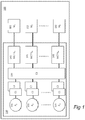
- FIG. 1 depicts a computer system comprising a microprocessor chip with one or a plurality of processing units, an exemplary cache hierarchy of three levels, and one or a plurality of memory controllers connected to one or a plurality of off-chip memories.
- FIG. 2 depicts a communication device comprising a data buffer storing a collection of data to be transferred to a peer communication device comprising a data buffer to store the transferred collection of data.
- FIG. 3 depicts an exemplary collection of data and how value frequency is established considering fixed-sized symbols.
- FIG. 4 depicts an exemplary collection of data and how value frequency is established considering variable-sized symbols.
- FIG. 5 depicts a computer system derived from FIG. 1 configured to 1) establish frequencies of symbols stored in the memories, 2) compress and 3) decompress the symbols.
- FIG. 6 depicts communication devices derived from FIG. 2 configured to 1) establish frequencies of symbols stored in the data buffers, 2) compress and 3) decompress the symbols to be transferred efficiently across the communication link.
- FIG. 7 depicts a value frequency table (VFT) to establish the frequencies of fixed-sized symbols to be used to form entropy-based encodings of symbols of a fixed size.
- VFT value frequency table
- FIG. 8 depicts a collection of value frequency tables to establish the frequencies of variable-sized symbols to form entropy-based encodings of such symbols.
- FIG. 9 depicts a system configured to and a flowchart describing the process of establishing entropy-based encodings for variable-sized symbols.
- FIG. 10 depicts a Huffman compressor (HuC) to compress fixed-sized symbols.
- HuC Huffman compressor
- FIG. 11 depicts a Huffman compressor (mHuC) to compress variable-sized symbols.
- FIG. 12 depicts a flowchart for a state machine controlling an exemplary Huffman compression process of variable-sized symbols.
- FIG. 13 depicts a Huffman decompressor (HuD) to compress fixed-sized symbols.
- FIG. 14 depicts a Huffman decompressor (mHuD) to decompress variable-sized symbols.
- FIG. 15 depicts a general method for variable-sized symbol, entropy-based data compression according to the invention.
- FIG. 16 depicts a general data compression device according to the invention.
- FIG. 17 depicts a general data decompression method according to the invention.
- FIG. 18 depicts a general data decompression device according to the invention.
- FIG. 19 depicts a general system comprising a data compression device and a data decompression device according to the invention.
- FIG. 1 An example of a computer system 100 is depicted in FIG. 1 .
- This system comprises a microprocessor chip 110 and one or a plurality of memory modules denoted M 1 151 , M 2 152 through M K 153 .
- the microprocessor chip could be a discrete system or integrated on a system-on-a-chip (SoC) in any available technology.
- the microprocessor 110 comprises one or several processing units, denoted P 1 131 , P 2 132 through P N 133 , sometimes called CPU or core, and a memory hierarchy.
- the memory hierarchy comprises several cache levels, e.g. three levels as is shown exemplary in FIG. 1 and denoted C 1 , C 2 , and C 3 .
- levels can be implemented in the same or different memory technologies, e.g. SRAM, DRAM, or any type of non-volatile technology including for example Phase-Change Memory (PCM).
- PCM Phase-Change Memory
- the number of cache levels may vary in different examples and the example 100 depicts three levels where the last cache level is C 3 120 . These levels are connected using some kind of interconnection means (e.g. bus or any other interconnection network).
- levels C 1 and C 2 are private to, and only accessible by, a respective processing unit i denoted P i (e.g. P 1 in FIG. 1 ).
- P i processing unit i
- alternative examples can have any number of private cache levels or, as an alternative, that all cache levels are shared as illustrated by the third level C 3 120 in FIG. 1 .
- the computer system 100 of FIG. 1 comprises one or a plurality of memory controllers, denoted MCTRL 1 141 , MCTRL 2 142 , through MCTRL K 143 .
- the last cache level (C 3 in FIG. 1 ) is connected to the memory controllers, which in turn are connected to one or a plurality of memory modules M 1 151 , M 2 152 , - - - .
- M k 153 which can be implemented in the same or different memory technologies, e.g.
- a task can be any software application or part of it that can run on the particular system.
- Computer systems can suffer from a limited capacity of the memory modules denoted M 1 151 through M K 153 and of the cache memories, regardless of level (e.g. C 1 , C 2 and C 3 in FIG. 1 ).
- a limited cache capacity can manifest itself as a higher fraction of memory requests having to be serviced at the next level in the memory hierarchy leading to loss in performance or higher energy consumption.
- To mitigate this problem one can consider increasing cache capacity, thereby lowering the number of requests that need to be serviced by the next level of the memory hierarchy.
- Increasing the capacity of the cache levels on a microprocessor chip will lead to a number of problems.
- the cache access request time can increase leading to performance loss.
- the energy consumed on an access request to a larger cache can potentially be higher.
- a limited memory capacity has similar problems and can manifest itself in more memory requests that will have to be serviced at the next level of the memory hierarchy typically realized as the storage level of the memory hierarchy. Such storage-level accesses are slower and may result in considerable loss in performance and energy expenditure. Increasing the memory capacity can mitigate these drawbacks. However, more memory capacity can increase the cost of the computer system both at the component level and in terms of energy expenditure.
- more memory consumes more space, which may limit the utility of the computer system in particular in form-factor constrained products including for example mobile computers (e.g., tablets, smart phones, wearables and small computerized devices connected to the Internet (a.k.a. Internet of Things (IoT) devices)).
- mobile computers e.g., tablets, smart phones, wearables and small computerized devices connected to the Internet (a.k.a. Internet of Things (IoT) devices).
- IoT Internet of Things
- FIG. 2 illustrates an exemplary data communication system 200 of communication devices 221 and 212 in two computerized sub-systems 201 , 202 with the ability to communicate over a communication link 230 .
- Each of the two communication devices 221 and 212 can communicate with one or a plurality of such communication devices, although in the exemplary system only two communication devices are shown.
- the communication devices can adhere to a communications protocol, e.g. TCP/IP, which typically has a number of standardized protocol levels.
- the task of a communication device is to transfer a collection of data from one point to another. For example, and as illustrated in FIG.
- this task may involve the transfer of a collection of data from communication device 221 to communication device 212 .
- the collection of data to be transferred is typically stored in a data buffer 211 accessible by communication device 212 and, analogously, the receiving communication device 221 typically deposits the received collection of data in a corresponding data buffer 222 .
- Data compression can alleviate the problems of limited memory and communication capacity in each of the examples of FIGS. 1 and 2 , and, more generally, in alternative examples as appreciated by someone skilled in the art.
- a first effect of the increased memory capacity is to be able to store more data in the available memory.
- a second effect is to allow data to be more effectively transferred from memory to the cache hierarchy on the microprocessor chip 110 in FIG. 1 by freeing up communication capacity on the interconnect between memory modules M 1 through M K and memory controllers MCTRL 1 141 through MCTRL K 143 .
- a third effect is to allow also data to be stored in a compressed format in the cache hierarchy.
- Entropy-based data compression is a class of lossless data compression methods well known per se in the prior art. As input, it considers a collection of data comprising a set of symbols of a certain a priori defined size.
- symbols could comprise the set of capital letters in the English alphabet, i.e., “A”, “B”, “C”, . . . , “Z”.
- symbols could comprise the set of 32-bit integers, i.e., 00000000 16 . . . FFFFFFFF 16 in hexadecimal notation.
- FIG. 3 an exemplary collection of data stored in a memory matrix 310 corresponding to five rows of eight memory locations each, where each location occupies fixed-sized symbols, e.g., 32-bits, exemplary interpreted as decimal numbers.
- locations are mapped to memory addresses row-by-row starting from address 0 at the top. That is, the locations of the first row are mapped to memory addresses 0, 1, . . . , 7; the locations of the second row are mapped to memory addresses 8, 9, . . . , 15 etc.
- some values are apparently more common than others. For example, the symbol with the decimal value 67 , e.g. in location 311 , and the symbol with the decimal value 68 , e.g. in location 312 occur 11 and 6 times, respectively, whereas e.g. the symbol with the decimal value 02 only occurs once.
- the idea behind entropy-based data compression is to code more frequent symbols with fewer bits than less frequent symbols. To generate such encodings, one must establish frequencies of occurrence of each symbol in a collection of data.
- FIG. 4 shows an exemplary memory matrix 410 with the same content as the memory matrix 310 of FIG. 3 .
- symbol sizes dictated by the size of a single memory location (e.g. 32 bits)
- the symbol corresponding to the second row 413 that is, “54 00 67 68 00 01 67 68” is the same as the one in the fourth row.
- the frequency table 420 shows the number of occurrences of each of the symbols in the memory matrix 410 , not taking into account whether a symbol i of size S i is included in a symbol j of size S j where S i ⁇ S j .
- symbol 413 “54 00 67 68 00 01 67 68” occurs twice whereas symbol 412 “67 68” and symbol 411 “67” occur six and nine times, respectively.
- This invention pertains to methods, devices and systems configured to sample, encode, compress, and decompress, respectively, symbols of variable size using entropy-based data compression principles which may be known per se in the prior art.
- the invention will first be described on a general level with reference to FIG. 15-19 .
- FIG. 5-6 we will describe how the examples of FIG. 1 and FIG. 2 may be extended into embodiments which allow entropy-based data compression and decompression methods to compress and decompress data in the memory and caches of the exemplary computer system in FIG. 1 and the data buffers in the communication system of FIG. 2 , respectively.
- FIG. 7-14 detailed exemplary embodiments of different parts and stages of the data compression and decompression methods and devices will be described with reference to FIG. 7-14 .
- FIG. 15 illustrates a general method for entropy-based data compression of variable-sized symbols according to the invention.
- FIG. 16 illustrates a general data compression device 1600 , capable of performing the data compression method of FIG. 15 .
- FIGS. 15 and 16 will now be described concurrently.
- the data compression device 1600 obtains a collection of data 1605 ( FIG. 16 ).
- this may typically involve reading the collection of data from a computer memory.
- a computer memory may, for instance, be an on-chip cache memory, an off-chip random access memory, a data buffer or a secondary data storage.
- Some non-limiting examples of such a computer memory are referred to as C 1 -C 3 ; M 1 -M k ; 610 - 650 in this document.
- the obtained collection of data 1605 contains variable-sized symbols 1606 , i.e. symbols of different symbol sizes S 1 -Sn. For instance, as seen in FIG. 16 , symbol SY has the size S 2 .
- the obtained collection of data 1605 is sampled by a sampler 1610 to establish, for a plurality of (i.e. all or at least some of) the different symbol sizes S 1 -Sn, relative frequencies 1615 of the symbols 1606 of the respective sizes in the collection of data 1605 .
- an encoder 1620 operates on sampled symbols in the collection of data 1605 to generate a code 1625 comprising variable-length codewords. For instance, sampled symbol SY is represented in the code 1625 by a codeword CW, as seen in FIG. 16 .
- the encoder 1620 generates the code 1625 by entropy encoding the sampled symbols in the collection of data 1605 based on a metric 1616 which reflects the relative frequencies 1615 of the sampled symbols as well as their sizes.
- the metric may be calculated by the sampler 1610 or the encoder 1620 .
- a compressor 1630 compresses symbols in the collection of data 1605 into compressed representations using the generated code 1625 .
- the compressed representation 1635 of each compressed symbol comprises the codeword (for instance the codeword CW) which represents the symbol (i.e. the symbol SY) as well as metadata MD for decompressing the compressed representation 1635 .
- the metadata MD may comprise a first portion 1151 ; V to indicate that the compressed representation 1635 of a symbol SY contains the codeword CW, and a second portion 1152 ; LEVEL to indicate a size of the symbol SY represented by the codeword CW.
- the compressed representations may typically be stored in a computer memory, such as for instance an on-chip cache memory, an off-chip random access memory, a data buffer or a secondary data storage.
- a computer memory such as for instance an on-chip cache memory, an off-chip random access memory, a data buffer or a secondary data storage.
- C 1 -C 3 some non-limiting examples of such a computer memory are referred to as C 1 -C 3 ; M 1 -M k ; 610 - 650 in this document.
- this computer memory may be the same as or different from the computer memory from which the collection of data 1605 was read according to arrow 1505 as described above.
- the data compression device 1600 in FIG. 16 may be implemented in hardware, e.g. as digital circuitry in an integrated circuit, as a programmable processing device (e.g. a central processing unit (CPU) or digital signal processor (DSP), as a field-programmable gate array (FPGA), etc.
- a programmable processing device e.g. a central processing unit (CPU) or digital signal processor (DSP), as a field-programmable gate array (FPGA), etc.
- the functionality of the data compression method in FIG. 15 may be performed by the data compression device 1600 being appropriately configured, or as a computer program product comprising code instructions which, when loaded and executed by a general-purpose processing device such as a CPU or DSP, cause performance of the method.
- sampler 1610 , encoder 1620 and compressor 1630 have been disclosed above with reference to FIG. 16 as being components of the data compression device 1600 , it shall be noticed that in alternative embodiments, the sampler 1610 , encoder 1620 and compressor 1630 may constitute separate devices. Also, two of the sampler 1610 , encoder 1620 and compressor 1630 may together constitute a combined device, for instance the sampler 1610 and the encoder 1620 , or the encoder 1620 and the compressor 1630 .
- FIG. 17 illustrates a general data decompression method according to the invention.
- FIG. 18 illustrates a general data decompression device 1800 , capable of performing the data decompression method of FIG. 17 .
- the data decompression device 1800 comprises a decompressor 1820 .
- FIGS. 17 and 18 will now be described concurrently.
- the decompressor 1820 obtains a compressed block 1810 comprising compressed representations 1804 , 1805 , 1806 of variable-sized symbols 1832 , wherein the compressed representations will have been generated by a data compression method and device 1600 as described above for FIGS. 15 and 16 .
- the obtaining step 1710 may typically involve reading 1705 the compressed block from a computer memory of any of the types referred to above for FIGS. 15 and 16 .
- the decompressor 1820 retrieves (step 1720 ) a compressed representation 1805 comprised in the compressed block 1810 , retrieves (step 1730 ) metadata MD comprised in the compressed representation 1805 , and retrieves (step 1740 ) a codeword CW comprised in the compressed representation 1805 .
- the decompressor 1820 decompresses the retrieved codeword CW into a symbol SY having one among a plurality of different sizes S 1 -Sn.
- the decompressor 1820 uses the retrieved metadata MD and a code 1824 comprising variable-length, entropy encoded codewords.
- the code 1824 will have been generated (as code 1625 ) by the encoder 1620 as described above with reference to FIG. 16 .
- the entropy encoding of the codewords of the code 1824 has been based on a metric 1826 (i.e. metric 1616 in FIG.
- the metadata MD may comprise a first portion 1151 ; V to indicate that the compressed representation 1635 of a symbol SY contains the codeword CW, and a second portion 1152 ; LEVEL to indicate a size of the symbol SY represented by the codeword CW.
- the decompressed symbol SY may typically be stored in a computer memory of any of the types referred to above for FIGS. 15 and 16 .
- the data decompression device 1800 in FIG. 18 may be implemented in hardware, e.g. as digital circuitry in an integrated circuit, as a programmable processing device (e.g. a central processing unit (CPU) or digital signal processor (DSP), as a field-programmable gate array (FPGA), etc.
- a programmable processing device e.g. a central processing unit (CPU) or digital signal processor (DSP), as a field-programmable gate array (FPGA), etc.
- the functionality of the data decompression method in FIG. 17 may be performed by the data decompression device 1800 being appropriately configured, or as a computer program product comprising code instructions which, when loaded and executed by a general-purpose processing device such as a CPU or DSP, cause performance of the method.
- FIG. 19 illustrates a general system 1900 according to the invention.
- the system comprises one or more memories 1910 , a data compression device 1920 and a data decompression device 1930 .
- the system 1900 is a computer system (such as the one which will be described as computer system 500 below with reference to FIG. 5 ), and said one or more memories 1910 is/are cache memory/memories (such as the cache memories C 1 -C 3 referred to in other parts of this document), random access memory/memories (such as the memories M 1 -M k referred to in other parts of this document), or secondary storage/storages.
- the system 1900 is a data communication system (such as the one which will be described as data communication system 600 below with reference to FIG. 6 ), and said one or more memories 1910 is/are data buffer(s) (such as the data buffers referred to as 610 , 650 ).
- FIG. 5-6 we will now describe how the examples of FIG. 1 and FIG. 2 may be extended into embodiments which allow entropy-based data compression methods to compress data in the memory and caches of the exemplary computer system in FIG. 1 and the data buffers in the communication system of FIG. 2 , respectively.
- the computer system of FIG. 1 is revisited and has been extended with three new devices: one or a plurality of entropy samplers 511 , one or a plurality of entropy compressors 512 and one or a plurality of entropy decompressors 513 .
- One skilled in the art will appreciate alternative embodiments as explained earlier in the context of FIG. 1 .
- the purpose of the entropy sampler 511 is to implement the sampler 1610 of FIG. 16 , i.e. to establish the frequency of symbols in a memory area located in one or a plurality of memory modules M 1 through M K or in one or a plurality of cache levels C 1 through C 3 and as described later.
- the purpose of the entropy compressor 512 is to implement the compressor 1630 of FIG. 16 , i.e. to compress a collection of data stored in any of the aforementioned memory locales based on an entropy-based encoding, as will be described in detail later.
- the entropy-based encoding may be established by an entropy encoder which will implement the encoder 1620 in FIG. 16 but which is however not shown in FIG. 5 .
- the entropy sampler 511 , entropy encoder and entropy compressor 512 may thus jointly implement the data compression device 1600 in FIG. 16 .
- the purpose of the entropy decompressor 513 is to implement the decompressor 1820 (or the entire data decompression device 1800 ) in FIG. 18 , i.e. to decompress a collection of data stored in any of the aforementioned memory locales, for example a cache or a main memory device, using an entropy-based encoding, as will be described in detail later.
- FIG. 6 we revisit an exemplary organization of a communications system including two computerized systems with the ability to communicate over a communication link 230 according to FIG. 2 .
- Communication devices 620 and 640 have been extended with an entropy sampler ( 621 and 641 ), an entropy compressor ( 622 and 642 ) and an entropy decompressor ( 623 and 643 ).
- entropy sampler 621 and 641
- the entropy decompressor 623 and 643
- the purpose of the entropy sampler 621 and 641 , respectively) is to implement the sampler 1610 of FIG. 16 , i.e.
- the purpose of the entropy compressor ( 622 and 642 , respectively) is to implement the compressor 1630 of FIG. 16 , i.e. to compress a collection of data in a data buffer ( 610 and 650 , respectively) based on an entropy encoding, as will be described later.
- the entropy-based encoding may be established by an entropy encoder which will implement the encoder 1620 in FIG. 16 but which is however not shown in FIG. 6 .
- the entropy sampler 621 / 641 , entropy encoder and entropy compressor 622 / 642 may thus jointly implement the data compression device 1600 in FIG. 16 .
- the purpose of the entropy decompressor ( 623 and 643 , respectively) is to implement the decompressor 1820 (or the entire data decompression device 1800 ) in FIG. 18 , i.e. to decompress a collection of data stored in a data buffer ( 610 and 650 , respectively) using an entropy-based encoding, as will be described in detail later.
- FIG. 7 shows a value-frequency table 700 (abbreviated VFT).
- the VFT is organized as an ordinary cache with one or a plurality of entries (for example 721 a and 721 b ). Unlike an ordinary cache that comprises a tag store and a value store, a VFT comprises a tag store 722 and a counter store 723 and the tag store is indexed by a symbol (or its value). As with ordinary caches, VFTs can employ a number of address mapping strategies such as direct-mapped, set-associative or fully associative. VFTs can also consider a number of replacement strategies such as LRU (Least Recently Used), LFU (Least Frequently Used) or other known strategies from prior art as can be appreciated by someone skilled in the art. The operation of a VFT is as follows.
- indexing the VFT with a value 710 corresponding to the symbol does a VFT look-up.
- a VFT look-up and depending on the address mapping mechanism employed, one or several entries are considered and the value is matched against the tags of the selected entries.
- hit the corresponding counter is incremented unless it has reached its maximum number.
- miss the new symbol is inserted and the corresponding counter is set to 1.
- To insert a new symbol one may have to evict another symbol.
- the symbol selected for eviction can be decided based on any known replacement strategy from prior art as described earlier. The process of counting the frequencies of all symbols in a memory area is repeated until all symbols have been encountered.
- the VFT of FIG. 7 assumes symbols of a fixed size determined at design time. We will later describe a sampler with a VFT extended to deal with symbols of variable size.
- the symbol frequencies established in the sampling process can be used by an entropy-based data compression method to determine symbol codes whose lengths are optimal according to Shannon's source coding theory.
- the code construction algorithm will start from the most frequent one, from the right in the example and going to the left. Therefore, the exemplary symbol “H” will be assigned to the canonical codeword “00” whose numerical value is 0 represented by 2 bits as its codeword length is 2. Symbol “G” will then be assigned to “01”. Symbol “F” will be replaced by a codeword of 3 bits. Since the last assigned code-word value is “01” to symbol “G”, symbol “F” will be assigned to the next numerical value, that is codeword “10”′ shifted by one bit to the left “100”, in order to be represented by 3 bits as the code length determines.
- the canonical Huffman codewords for the above values are constructed and are respectively “1111”, “1110”, “1101”, “1100”, “101”, “100”, “01”, “00”. While this is one way of generating canonical Huffman codewords, as anyone skilled in the art will appreciate, there are alternative ways of generating canonical Huffman codewords depending on the codeword length that the code generation algorithm starts with. Note that a process as the one outlined assumes that all symbols have a fixed size and cannot deal with symbols of variable size.
- the sampler 800 comprises a plurality of parallel sampler units 812 - 852 .
- Each sampler unit is configured to establish the relative frequency of occurrence of symbols of a respective one of the aforementioned plurality of different symbol sizes S 1 -Sn.
- the exemplary variable-sized symbol sampler 800 of FIG. 8 hence comprises five parallel sampler units 812 - 852 with an organization according to FIG. 7 , where each is configured to count the frequency of occurrence of symbols of a respective fixed symbol size. Accordingly, the sampler 800 of FIG.
- VFT 8 comprises the five sampler units 812 - 852 which are also denoted VFT 4 , VFT 8 , VFT 16 , VFT 32 , and VFT 64 , corresponding to symbols of size 4 bytes, 8 bytes, 16 bytes, 32 bytes and 64 bytes, respectively.
- the process of determining the frequency of occurrence of variable-sized symbols starts with copying a block of 64-byte data from the selected memory area into all of the buffers 811 , 821 , 831 , 841 and 851 . Referring back to the VFT of FIG.
- the tag store of VFT 64 is used to match against 64-byte symbols whereas the tag store of VFT 4 is used to match against 4-byte symbols.
- the process of evaluating a 64-byte memory block involves 16 matching operations in VFT 4 , 8 matching operations in VFT 8 , four matching operations in VFT 16 , two matching operations in VFT 32 and one matching operation in VFT 64 . This process is repeated for the entire selected memory area.
- the counters in the VFTs can be memory mapped so that their content can be examined by software routines.
- hardware accelerators can be configured to process the contents of the counters so as to establish entropy-based encodings.
- the symbol frequencies established in the sampling process can be used by an entropy-based data compression method to generate codes.
- entropy-based encoding methods in prior art assume that all symbols have the same size. This can yield substantially lower compressibility than if variable-sized symbols are considered.
- the coding of the longest symbol i.e., “GHIJKLMN” will have a higher impact on compressibility than the coding of the shortest symbol, i.e., “A”.
- One embodiment of the disclosed invention first sorts symbols in ascending order based on the removed-slot metric defined as the product of the probability of symbol occurrence and symbol weight, where symbol weight is defined as the size of a symbol divided by the maximum size of a symbol.
- the removed-slot metric for the aforementioned exemplary list of symbols is 0.15 ⁇ 8/8, 0.15 ⁇ 4/8, 0.2 ⁇ 2/8, 0.25 ⁇ 1 ⁇ 8 leading to 0.15, 0.075, 0.05, and 0.03, respectively.
- the above process assumes that a symbol of one size is not included in a symbol of another larger size. To account for inclusion, it is proposed that the above process first removes a first symbol of one size included in a second symbol of a larger size to calculate a metric of occurrence of a first symbol. In this process, the symbol frequency of a first symbol is adjusted to account for its occurrence in a second symbol of a larger size.
- An exemplary system configured to implement this process and an exemplary logic to accomplish the result of such a process is described in FIG. 9 .
- FIG. 9 illustrates a system 9100 configured to take as input variable-sized symbols, referred to as “Original Symbols—denoted OSym, exemplary stored in a memory 9110 , each comprising attributes for their size, denoted “S”, and probability of occurrence, denoted “P”, determined in the sampling process described above.
- the exemplary system 9100 is configured to generate the content of a memory of “Resulting Symbols”—denoted Rsym, exemplary stored in a memory 9160 , where each entry is comprising attributes of “Removed slots”—denoted RS, as defined in detail above.
- the exemplary system 9100 additionally comprises a state machine 9150 that can analyze each entry in memory 9110 comprising an OSym to output its corresponding RS to the memory 9160 .
- the state machine 9150 can be configured to access any entry in memory 9110 and 9160 . Specifically, it can move the content of an entry in memory 9110 to a register 9120 , denoted Symbol R 1 or to a register 9140 by comprising relevant signals to access memory 9110 , for example a read signal R in FIG. 9 that comprises an address to memory 9110 and reference to any of the aforementioned registers 9120 or 9140 .
- state machine 9150 can also shift the content of register 9140 by an amount that corresponds to the size “S” of that register, as specified above, of a symbol being examined.
- the exemplary system 9100 comprises a comparator 9130 that takes as input a symbol stored in register R 1 9120 and a portion, dictated by a size attribute “S”, provided by state machine 9150 . The result of the comparison is reflected by a signal denoted “M” for match. For example, if there is a match, “M” is set. Conversely, if there is no match, “M” is cleared.
- OSym original symbols
- S size of size
- state machine 9150 moves symbols appearing in entries Pos and N to register R 1 and R 2 , respectively.
- the comparator 9130 of the state machine 9150 compares the content of registers R 1 and R 2 based on the size attribute associated with register R 2 and as dictated by signal “S” of system 9100 . If there is a match, the probability “P” of the symbol presently available in register R 2 is adjusted taking into account the probability “P” of the symbol presently available from register R 1 . This operation is represented by the box denoted “Adjust P for OSym(N).” If there is no match, i.e. “M” is cleared, this operation is skipped. Regardless of the outcome, the next step is to shift the content of R 2 by an amount that corresponds to the size “S” of the symbol stored in R 2 .
- the comparison aims at determining whether there is a match between a portion of a first symbol of one size S 1 and a second symbol of another, smaller size S 2 .
- the exemplary process to carry out that comparison will match a second symbol with all parts of a first symbol that matches the size of a second symbol.
- state machine 9150 can shift the content of the symbol of size S 2 in R 2 to match all parts of the symbol of size S 1 in R 1 . This is accomplished by shifting the content of R 2 with an amount dictated by “S” output from state machine 9150 and carried out in the box in 9200 denoted “Shift R 2 ”.
- the decision box “DONE” can then decide whether all portions of register 9120 have been matched, denoted “Y”, or if additional portions must be compared, denoted “No”. If the outcome is the latter, a new comparison between R 1 and R 2 is carried out until all portions have been compared.
- the content of register R 2 9140 is compared to the next larger symbol as denoted by the flow following “Y” in the decision box denoted “Done”. This is defined by the entry associated by the logical variable “Pos”, initially set to 1. As shown in the flow following the arrow from “Y” in the decision box denoted “Done”, Pos is decremented.
- system 9100 and the logic 9200 controlling that system can be realized also by an ordinary computer configured by a program to carry out a process exemplified by process 9200 configuring memory and registers in said computer to implement the system 9100 needed to carry out the process 9200 .
- Other embodiments appreciated by someone skilled in the art may consider some parts implemented in hardware to gain efficiency and some parts in software by means of a program that may not be critical to efficiency in carrying out the task.
- the exemplary system and process of FIG. 9 can establish an encoding of variable-sized symbols, i.e. implement the encoder 1620 in FIG. 16 as one possible embodiment thereof.
- the encoder 1620 is hence configured to compensate for a first symbol of a smaller symbol size Sx being included in a second symbol of a larger symbol size Sy, where Sx ⁇ Sy, such that the occurrence of said first symbol is accounted for in the relative frequency established for the larger symbol size but not in the relative frequency established for the smaller symbol size.
- FIG. 10 depicts an embodiment 1000 of an exemplary Huffman Compression Mechanism for fixed-size symbols.
- the exemplary compressor 1000 comprises a Value Table (VT) 1020 .
- the VT 1020 saves the values of the symbols to be compressed 1022 and their frequency of occurrence using the counter 1024 .
- the compressor 1000 also comprises a Code Table (CT) 1030 which stores the generated codewords which make up the aforementioned code 1625 .
- CT Code Table
- the VT is part of the compression mechanism 1000 because both VT 1020 and CT 1030 are indexed using the address association mechanism 1010 that matches an input value corresponding to a symbol with a codeword, and the VT 1020 verifies that a particular symbol exists in the Value Table and, hence, a valid codeword exists in the Code Table.
- the association function in the compression mechanism 1010 can be implemented as a hash function, but someone skilled in the art can consider alternative implementations.
- the exemplary compressor 1100 which implements the compressor 1630 in FIG. 16 as one possible embodiment thereof, comprises a plurality of Huffman compressor units 1111 - 1115 , each being designed generally as the compressor 1000 in FIG. 10 .
- the compressor 1100 comprises a plurality of parallel compressor units 1111 - 1115 adapted to receive a common data block 1111 a - 1115 a from the aforementioned collection of data 1510 .
- Each compressor unit 1111 - 1115 is configured to identify in said common data block a matching symbol of a respective one of said plurality of different symbol sizes S 1 -Sn.
- the compressor 1100 is configured to output a codeword corresponding to a symbol having the largest symbol size among matching symbols identified by the compressor units 1111 - 1115 .
- each compressor unit 1111 - 1115 there is a 64-byte register 1111 a , 1112 a , . . . , 1115 a associated with each compressor unit 1111 - 1115 .
- the process of compressing a 64-byte block of data starts with loading that common data block into all five 64-byte registers that feed into the compressor units.
- each compressor unit outputs a signal, denoted Match, and a codeword.
- All Match signals constitute input to a 5-to-3 priority encoder 1120 that outputs the highest encoded level at which a match is detected. For example, assuming that there is a match at level 0 (HuC 4 ) and level 2 (HuC 16 ), the priority encoder 1120 would output 010 corresponding to level 2.
- the codewords of the matched levels are fed into a plurality of tri-state buffers 1140 ; five in the exemplary compressor.
- a3-5 demultiplexer On a match at any level, a3-5 demultiplexer, whose input is the encoded level, will activate the corresponding tri-state buffer to output the codeword of that level.
- the corresponding codeword along with metadata is also fed into a register 1150 comprising three parts: a valid (V) bit 1151 , a level 1152 and a codeword 1153 , wherein the valid bit 1151 and the level 1152 constitutes the metadata MD as referred to in the description above of FIG. 15-18 .
- the V bit designates that the information that follows is a compressed symbol.
- the level designates the size of the (uncompressed) symbol and the codeword is the compressed symbol according to the entropy-based data compression method of choice. If there is no match, the valid bit is cleared. This means that there is no match at any level so the symbol of the smallest size is output, uncompressed, and the level information is not relevant.
- all 4-byte symbols in a 64-byte block of data cannot be compressed, one could encode the entire block as not compressed at the level of 64 bytes, as an optimization.
- someone skilled in the art can appreciate how the working of the variable-sized symbol compressor can be extended to incorporate such and other optimizations.
- the exemplary state machine 1160 is configured to control the compression process and the underlying process of its working is described in the flow chart described in FIG. 12 .
- the state machine takes as input a Valid signal flagging whether there is a match at any level and the encoding of the level of a match.
- the state machine output comprises a set of shift signals (SHIFT) that can control each of the five input registers connected as input to the five compressors: HuC 4 1115 , HuC 8 1114 , HuC 16 1113 , HuC 32 1112 and HuC 64 1111 .
- the state machine can also control which levels should be tested for matching by masking levels higher than a preset value. For example, if SET MAX LEVEL is set to three, only the compressors associated with level 0, 1, 2 and 3 are considered for matching.
- the process starts by setting the level to MAXL, the maximum level for the test, which is five in the exemplary compressor of FIG. 11 .
- the input registers at the level of a match or lower, and in the limit MINL, are shifted an amount corresponding to the level at which a match occurred, or if no match occurred, MINL.
- the decision box 1216 decides whether all of the symbols in the 64-byte block have been tested, in which case the process terminates. If not, a new test is carried out at the preset level ( 1218 ) and below, a codeword is generated ( 1219 ), and the input registers are shifted ( 1220 ) according to the process described above. For example, if a match occurs at the current level, the code for that level is output. On the other hand, if no match occurs, the level will remain at MINL and an uncompressed symbol is output.
- the decision box 1221 decides whether all of the symbols in the 64-byte block have been tested, in which case the process terminates. If not, the level is doubled 1223 and the input registers are shifted by the doubled amount 1224 before a new match operation is carried out in decision box 1211 .
- the compressor 1630 ; 1100 is configured to take as input a symbol of a given size and interpret that symbol as twice as many symbols of half the given size and as four times as many symbols of a quarter of the given size, etc, and compare all combinations of symbols against encoded symbols of all sizes considered.
- the doubling stems from the fact that the exemplary symbol sizes are chosen to follow a power series of two. If another power series is followed, someone skilled in the art should realize how to adapt the above process for that power series or to other series of symbol sizes.
- FIG. 13 shows the working of an exemplary fixed-sized symbol canonical Huffman decompressor.
- decompression starts at the barrel shifter 1310 , the width of which is at least d′ bits (the maximum codeword length), and inputs the compressed block.
- the compressed block can be also kept in a buffer to provide the bit sequence to the barrel shifter based on the shifting amount.
- the comparator 1320 a compares 1 bit, the comparator 1320 b two bits, and the comparator 1320 c three bits etc. Since it is possible that no codewords are generated for particular lengths, a valid bit is used and sent to the comparators 1320 ( 1320 a , 1320 b , 1320 c , etc) to cancel the comparison when there are non-existing codewords for particular lengths but other alternatives can be realized by someone skilled in the art.
- the numerical sequence property one can assume that a valid codeword will be numerically larger than any numeric value of codewords of smaller lengths. Therefore, the largest detected codeword is the only valid one which is why the priority encoder 1330 is used.
- the second operation begins.
- the length of the matched codeword is used to access the DIT 1350 to obtain the appropriate “offset”, while the bits of the matched codeword are provided by the barrel shifter 1310 and are concatenated in the unit 1340 .
- the index to the De-LUT 1370 is found by subtracting the “offset” from the matched codeword and take as many least significant bits as needed to access the De-LUT 1370 . In an alternative embodiment, where the offset is positive, it would be added instead of being subtracted.
- the decompressor 1400 implements, as one possible embodiment, the decompressor 1800 in FIG. 18 .
- the assumed compressed format 1410 is already described in relation to the aforementioned description of the exemplary entropy variable-sized symbol compressor of FIG. 11 along with the compression process of FIG. 12 and comprises three fields: a valid bit 1411 , a level 1412 and a codeword 1413 .
- the exemplary decompressor assumes five symbol sizes: 4 bytes, 8 bytes, 16 bytes, 32 bytes and 64 bytes.
- HuD 4 1431 e HuD 8 1431 d
- HuD 16 1431 c HuD 32 1431 b
- HuD 64 1431 a where HuD i decompresses symbols of size i bytes.
- the contents of the value tables inside these decompressor units can be established during the encoding process and loaded into said value tables before the decompression process starts.
- the corresponding decompressor unit is selected by the 3-5 demultiplexer 1420 by the enable signals EN 1 1421 e , EN 2 1421 d , .
- a set of five tri-state buffers 1440 can be optionally used to select one symbol 1451 out of five decompressed symbols.
- the code length information retrieved from the decompression process can be used to select the location of the next symbol to be decompressed (Length 1450 ). Alternatively, if the symbol is not compressed, an uncompressed 4-byte word is retrieved and the location of the next potentially compressed symbol can be determined.
- the invention generally pertains to variable-sized symbol entropy-based compression and comprises sampling, encoding, compression and decompression of a collection of data stored in a memory.
- One alternative inventive aspect is a computer-based device storing a collection of data comprising symbols of variable size in a memory providing a means for sampling, encoding, compressing and decompressing said collection of data.
- This alternative inventive aspect comprises a means for sampling, i.e., establishment of the relative frequency of said variable-sized symbols.
- this alternative inventive aspect comprises a means to encode said variable-length symbols with respect to code length of the variable-sized symbols concerning the resulting size of the encoded collection of data built from the symbols.
- This alternative inventive aspect additionally comprises a means of compressing said variable-sized symbols into a format comprising information of how to decompress said collection of data.
- this alternative inventive aspect comprises a means of how to decompress a collection of data compressed by an entropy-based compression method using the disclosed principles to deal with variable-sized symbols to resurrect the originally uncompressed data using the disclosed method of encoding and compressing a collection of data comprising variable-sized symbols.
- Another alternative inventive aspect is a method for sampling, encoding, compressing and decompressing a collection of data stored in a memory, e.g., a data buffer, a computer memory, a computer cache, or a secondary storage using symbols of variable size.
- This alternative inventive aspect comprises a step of sampling, i.e., how to establish the relative frequency of said variable-sized symbols.
- this alternative inventive aspect comprises a step of encoding said variable-sized symbols with respect to code length of the variable-sized symbols concerning the resulting size of the encoded collection of data stored in a memory built from the variable-sized symbols.
- This alternative inventive aspect additionally comprises a step of compressing said variable-size symbols stored in a memory into a format comprising information of how to decompress said collection of data.
- this alternative inventive aspect additionally comprises how to decompress a collection of data originally comprising variable-sized symbols and compressed by entropy-based compression using the disclosed principles to resurrect the originally uncompressed data.
- Yet another alternative inventive aspect is a system operating on a computer memory storing a collection of data comprising symbols of variable size configured to sample, encode, compress and decompress said collection of data.
- Said system is configured to sample the symbols in a memory to establish the relative frequency of said variable-sized symbols.
- said system is configured to encode with respect to code length of the variable-sized symbols concerning the resulting size of the encoded collection of data built from the symbols.
- Said system is additionally configured to compress said variable-size symbols into a format comprising information of how to decompress said collection of data.
- said system is configured to decompress a collection of data compressed by entropy-based compression using the disclosed principles to resurrect the originally uncompressed data using the disclosed method of encoding and compressing a collection of data comprising variable-sized symbols.
- a sampler configured to establish the frequency of said symbols
- an encoder configured to generate an entropy-based code for said symbols
- a compressor that based on said code for said collection of data is configured to generate compressed codes and an instruction for decompressing the same;
- a decompressor that based on said instruction is configured to decompress said collection of data to the original uncompressed format.
Landscapes
- Engineering & Computer Science (AREA)
- Theoretical Computer Science (AREA)
- Compression, Expansion, Code Conversion, And Decoders (AREA)
Abstract
Description
Claims (21)
probability of symbol occurrence=relative frequency of symbol/number of different symbols, and
symbol weight=size of symbol/maximum symbol size.
probability of symbol occurrence=relative frequency of symbol/number of different symbols, and
symbol weight=size of symbol/maximum symbol size.
Applications Claiming Priority (4)
| Application Number | Priority Date | Filing Date | Title |
|---|---|---|---|
| SE1650426 | 2016-03-31 | ||
| SE1650426A SE542507C2 (en) | 2016-03-31 | 2016-03-31 | Variable-sized symbol entropy-based data compression |
| SE1650426-8 | 2016-03-31 | ||
| PCT/SE2017/050265 WO2017171611A1 (en) | 2016-03-31 | 2017-03-20 | Variable-sized symbol entropy-based data compression |
Publications (2)
| Publication Number | Publication Date |
|---|---|
| US20200304146A1 US20200304146A1 (en) | 2020-09-24 |
| US10862507B2 true US10862507B2 (en) | 2020-12-08 |
Family
ID=59966198
Family Applications (1)
| Application Number | Title | Priority Date | Filing Date |
|---|---|---|---|
| US16/087,630 Active 2037-11-24 US10862507B2 (en) | 2016-03-31 | 2017-03-20 | Variable-sized symbol entropy-based data compression |
Country Status (4)
| Country | Link |
|---|---|
| US (1) | US10862507B2 (en) |
| CN (1) | CN109075798B (en) |
| SE (1) | SE542507C2 (en) |
| WO (1) | WO2017171611A1 (en) |
Families Citing this family (11)
| Publication number | Priority date | Publication date | Assignee | Title |
|---|---|---|---|---|
| CN111384968B (en) * | 2018-12-28 | 2022-08-09 | 上海寒武纪信息科技有限公司 | Data compression/decompression device and data decompression method |
| CN112181919A (en) * | 2019-07-05 | 2021-01-05 | 深信服科技股份有限公司 | Compression method, compression system, electronic equipment and storage medium |
| US11226740B2 (en) * | 2019-10-30 | 2022-01-18 | EMC IP Holding Company LLC | Selectively performing inline compression based on data entropy |
| US11095311B2 (en) * | 2019-11-27 | 2021-08-17 | Qualcomm Incorporated | Quantization codeword selection for low cost parity checking |
| US11540275B2 (en) * | 2020-05-05 | 2022-12-27 | Telefonaktiebolaget Lm Ericsson (Publ) | Signaling structure for data signaling |
| CN112527752B (en) * | 2020-12-08 | 2024-04-05 | 北京地平线信息技术有限公司 | Data compression method, data compression device, computer readable storage medium and electronic equipment |
| CN114614829B (en) * | 2020-12-09 | 2024-12-31 | 千寻位置网络有限公司 | Satellite data frame processing method, device, electronic device and readable storage medium |
| CN114915295B (en) * | 2022-05-09 | 2024-06-11 | 重庆邮电大学 | A symbol encoding method that exceeds the entropy limit under certain conditions |
| CN115296774B (en) * | 2022-07-31 | 2025-03-14 | 航天科工通信技术研究院有限责任公司 | A method for framing using common data compression binary code |
| CN118337217A (en) * | 2023-01-12 | 2024-07-12 | 华为技术有限公司 | Method for compressing data, method, device, system and medium for decompressing data |
| CN118820194B (en) * | 2024-09-18 | 2024-11-29 | 天津金城银行股份有限公司 | Data compression management method, system, device and storage medium |
Citations (5)
| Publication number | Priority date | Publication date | Assignee | Title |
|---|---|---|---|---|
| WO2000036751A1 (en) | 1998-12-14 | 2000-06-22 | Microsoft Corporation | Code book construction for variable to variable length entropy encoding |
| US20140152475A1 (en) * | 2011-01-19 | 2014-06-05 | Kyoung Lae Cho | Data compression devices, operating methods thereof, and data processing apparatuses including the same |
| US20160099723A1 (en) * | 2014-10-07 | 2016-04-07 | Doron Kletter | Enhanced data compression for sparse multidimensional ordered series data |
| US20160254824A1 (en) * | 2013-11-26 | 2016-09-01 | Longsand Limited | Determining compression techniques to apply to documents |
| US20200186047A1 (en) * | 2018-12-06 | 2020-06-11 | Infineon Technologies Austria Ag | Circuits and Methods for Secondary-Side Rectified Voltage Sensing in Isolated Switched-Mode Power Converters |
-
2016
- 2016-03-31 SE SE1650426A patent/SE542507C2/en unknown
-
2017
- 2017-03-20 US US16/087,630 patent/US10862507B2/en active Active
- 2017-03-20 WO PCT/SE2017/050265 patent/WO2017171611A1/en not_active Ceased
- 2017-03-20 CN CN201780024207.4A patent/CN109075798B/en active Active
Patent Citations (5)
| Publication number | Priority date | Publication date | Assignee | Title |
|---|---|---|---|---|
| WO2000036751A1 (en) | 1998-12-14 | 2000-06-22 | Microsoft Corporation | Code book construction for variable to variable length entropy encoding |
| US20140152475A1 (en) * | 2011-01-19 | 2014-06-05 | Kyoung Lae Cho | Data compression devices, operating methods thereof, and data processing apparatuses including the same |
| US20160254824A1 (en) * | 2013-11-26 | 2016-09-01 | Longsand Limited | Determining compression techniques to apply to documents |
| US20160099723A1 (en) * | 2014-10-07 | 2016-04-07 | Doron Kletter | Enhanced data compression for sparse multidimensional ordered series data |
| US20200186047A1 (en) * | 2018-12-06 | 2020-06-11 | Infineon Technologies Austria Ag | Circuits and Methods for Secondary-Side Rectified Voltage Sensing in Isolated Switched-Mode Power Converters |
Non-Patent Citations (5)
| Title |
|---|
| International Preliminary Report on Patentability dated May 15, 2018 by the International Searching Authority for International Application No. PCT/SE2017/050265, filed on Mar. 20, 2017 and published as WO 2017/171611 on Oct. 5, 2017 (Applicant-Zeropoint Technologies AB) (15 Pages). |
| International Preliminary Report on Patentability dated May 15, 2018 by the International Searching Authority for International Application No. PCT/SE2017/050265, filed on Mar. 20, 2017 and published as WO 2017/171611 on Oct. 5, 2017 (Applicant—Zeropoint Technologies AB) (15 Pages). |
| International Search Report and Written Opinion dated Jun. 15, 2017 by the International Searching Authority for International Application No. PCT/SE2017/050265, filed on Mar. 20, 2017 and published as WO 2017/171611 on Oct. 5, 2017 (Applicant-Zeropoint Technologies AB) (13 Pages). |
| International Search Report and Written Opinion dated Jun. 15, 2017 by the International Searching Authority for International Application No. PCT/SE2017/050265, filed on Mar. 20, 2017 and published as WO 2017/171611 on Oct. 5, 2017 (Applicant—Zeropoint Technologies AB) (13 Pages). |
| Kozuch, M et al. "Compression of embedded system programs; Computer Design: VLSI in Computers and Processors", 1994. ICCD '94. Proceedings; IEEE International Conference on Cambridge, MA, USA Oct. 10-12, 1994, Publication date Oct. 10, 1994; Los Alamitos, CA, USA, IEEE Comput. Soc; p. 270-277. |
Also Published As
| Publication number | Publication date |
|---|---|
| SE1650426A1 (en) | 2017-10-01 |
| SE542507C2 (en) | 2020-05-26 |
| CN109075798A (en) | 2018-12-21 |
| US20200304146A1 (en) | 2020-09-24 |
| WO2017171611A1 (en) | 2017-10-05 |
| CN109075798B (en) | 2022-12-23 |
Similar Documents
| Publication | Publication Date | Title |
|---|---|---|
| US10862507B2 (en) | Variable-sized symbol entropy-based data compression | |
| US10819369B2 (en) | Methods, devices and systems for hybrid data compression and decompression | |
| US10268380B2 (en) | Methods, devices and systems for semantic-value data compression and decompression | |
| US7982636B2 (en) | Data compression using a nested hierachy of fixed phrase length static and dynamic dictionaries | |
| US6614368B1 (en) | Data compression method and apparatus utilizing cascaded character tables | |
| US20060106870A1 (en) | Data compression using a nested hierarchy of fixed phrase length dictionaries | |
| US9344114B1 (en) | Compressed caching in a virtual memory system | |
| US12360895B2 (en) | Systems, methods and devices for exploiting value similarity in computer memories | |
| US10103747B1 (en) | Lossless binary compression in a memory constrained environment | |
| CN116683914A (en) | Data compression method, device and system | |
| US12554635B2 (en) | Data compression circuit, memory system and method for controlling the data compression circuit | |
| US20250284632A1 (en) | Data compression circuit, memory system and method for controlling the data compression circuit | |
| US6653950B2 (en) | Data compression method and apparatus utilizing cascaded subdictionaries | |
| HK40089078A (en) | Systems, methods and devices for exploiting value similarity in computer memories | |
| CN120973288A (en) | Methods for searching data on a disk and methods for generating disk data indexes | |
| Munasa et al. | Single Dictionary based Cache Compression and Decompression Algorithm |
Legal Events
| Date | Code | Title | Description |
|---|---|---|---|
| FEPP | Fee payment procedure |
Free format text: ENTITY STATUS SET TO UNDISCOUNTED (ORIGINAL EVENT CODE: BIG.); ENTITY STATUS OF PATENT OWNER: SMALL ENTITY |
|
| FEPP | Fee payment procedure |
Free format text: ENTITY STATUS SET TO SMALL (ORIGINAL EVENT CODE: SMAL); ENTITY STATUS OF PATENT OWNER: SMALL ENTITY |
|
| AS | Assignment |
Owner name: ZEROPOINT TECHNOLOGIES AB, SWEDEN Free format text: ASSIGNMENT OF ASSIGNORS INTEREST;ASSIGNOR:STENSTROM, PER;REEL/FRAME:047952/0042 Effective date: 20181018 |
|
| STPP | Information on status: patent application and granting procedure in general |
Free format text: NOTICE OF ALLOWANCE MAILED -- APPLICATION RECEIVED IN OFFICE OF PUBLICATIONS |
|
| STCF | Information on status: patent grant |
Free format text: PATENTED CASE |
|
| MAFP | Maintenance fee payment |
Free format text: PAYMENT OF MAINTENANCE FEE, 4TH YR, SMALL ENTITY (ORIGINAL EVENT CODE: M2551); ENTITY STATUS OF PATENT OWNER: SMALL ENTITY Year of fee payment: 4 |