US10862319B2 - Battery module with abnormality detection function and power storage apparatus and method of operating the same - Google Patents
Battery module with abnormality detection function and power storage apparatus and method of operating the same Download PDFInfo
- Publication number
- US10862319B2 US10862319B2 US16/020,336 US201816020336A US10862319B2 US 10862319 B2 US10862319 B2 US 10862319B2 US 201816020336 A US201816020336 A US 201816020336A US 10862319 B2 US10862319 B2 US 10862319B2
- Authority
- US
- United States
- Prior art keywords
- protection unit
- battery
- indication element
- power storage
- storage apparatus
- Prior art date
- Legal status (The legal status is an assumption and is not a legal conclusion. Google has not performed a legal analysis and makes no representation as to the accuracy of the status listed.)
- Active, expires
Links
Images


Classifications
-
- H02J7/0026—
-
- H—ELECTRICITY
- H01—ELECTRIC ELEMENTS
- H01M—PROCESSES OR MEANS, e.g. BATTERIES, FOR THE DIRECT CONVERSION OF CHEMICAL ENERGY INTO ELECTRICAL ENERGY
- H01M10/00—Secondary cells; Manufacture thereof
- H01M10/42—Methods or arrangements for servicing or maintenance of secondary cells or secondary half-cells
- H01M10/48—Accumulators combined with arrangements for measuring, testing or indicating the condition of cells, e.g. the level or density of the electrolyte
-
- H—ELECTRICITY
- H01—ELECTRIC ELEMENTS
- H01M—PROCESSES OR MEANS, e.g. BATTERIES, FOR THE DIRECT CONVERSION OF CHEMICAL ENERGY INTO ELECTRICAL ENERGY
- H01M10/00—Secondary cells; Manufacture thereof
- H01M10/42—Methods or arrangements for servicing or maintenance of secondary cells or secondary half-cells
- H01M10/46—Accumulators structurally combined with charging apparatus
-
- H—ELECTRICITY
- H01—ELECTRIC ELEMENTS
- H01M—PROCESSES OR MEANS, e.g. BATTERIES, FOR THE DIRECT CONVERSION OF CHEMICAL ENERGY INTO ELECTRICAL ENERGY
- H01M10/00—Secondary cells; Manufacture thereof
- H01M10/42—Methods or arrangements for servicing or maintenance of secondary cells or secondary half-cells
- H01M10/48—Accumulators combined with arrangements for measuring, testing or indicating the condition of cells, e.g. the level or density of the electrolyte
- H01M10/482—Accumulators combined with arrangements for measuring, testing or indicating the condition of cells, e.g. the level or density of the electrolyte for several batteries or cells simultaneously or sequentially
-
- H—ELECTRICITY
- H01—ELECTRIC ELEMENTS
- H01M—PROCESSES OR MEANS, e.g. BATTERIES, FOR THE DIRECT CONVERSION OF CHEMICAL ENERGY INTO ELECTRICAL ENERGY
- H01M50/00—Constructional details or processes of manufacture of the non-active parts of electrochemical cells other than fuel cells, e.g. hybrid cells
- H01M50/50—Current conducting connections for cells or batteries
- H01M50/569—Constructional details of current conducting connections for detecting conditions inside cells or batteries, e.g. details of voltage sensing terminals
-
- H02J7/0021—
-
- H02J7/50—
-
- H02J7/62—
-
- H02J7/82—
-
- H—ELECTRICITY
- H02—GENERATION; CONVERSION OR DISTRIBUTION OF ELECTRIC POWER
- H02J—CIRCUIT ARRANGEMENTS OR SYSTEMS FOR SUPPLYING OR DISTRIBUTING ELECTRIC POWER; SYSTEMS FOR STORING ELECTRIC ENERGY
- H02J7/00—Circuit arrangements for charging or depolarising batteries or for supplying loads from batteries
- H02J7/0068—Battery or charger load switching, e.g. concurrent charging and load supply
-
- H02J7/865—
-
- Y—GENERAL TAGGING OF NEW TECHNOLOGICAL DEVELOPMENTS; GENERAL TAGGING OF CROSS-SECTIONAL TECHNOLOGIES SPANNING OVER SEVERAL SECTIONS OF THE IPC; TECHNICAL SUBJECTS COVERED BY FORMER USPC CROSS-REFERENCE ART COLLECTIONS [XRACs] AND DIGESTS
- Y02—TECHNOLOGIES OR APPLICATIONS FOR MITIGATION OR ADAPTATION AGAINST CLIMATE CHANGE
- Y02E—REDUCTION OF GREENHOUSE GAS [GHG] EMISSIONS, RELATED TO ENERGY GENERATION, TRANSMISSION OR DISTRIBUTION
- Y02E60/00—Enabling technologies; Technologies with a potential or indirect contribution to GHG emissions mitigation
- Y02E60/10—Energy storage using batteries
Definitions
- the present invention relates to a battery module and a power storage apparatus and a method of operating the same, and more particularly to a battery module with an abnormality detection function and a power storage apparatus and a method of operating the same.
- UPS uninterruptible power supply
- the UPS uninterruptedly supplies the required power to the critical commercial devices, such as the server and switch or precision devices to prevent the loss of important data stored in the critical commercial devices or the precision devices from the interrupted power supply.
- the used power storage device inside the UPS is commonly the rechargeable battery.
- the fuse is cooperated with the rechargeable battery to protect the rechargeable battery by the failure isolation.
- the fuses are usually used to protect a plurality of battery modules as a whole according a total current of the battery modules as a whole.
- the existing protection fails to individually provide protection and detect abnormal operation for single battery module. Once any one of the battery modules is abnormal, however, it fails to accurately and quickly determine which battery module is abnormal, thereby affecting the efficiency of excluding the abnormal condition.
- An objective of the present invention is to provide a battery module with an abnormality detection function to solve the above-mentioned problems of failing to individually provide protection and detect abnormal operation for single battery module.
- the battery module with the abnormality detection function includes a body, a battery assembly, a protection unit, and a detection unit.
- the battery assembly is disposed inside the body, and the battery assembly has a plurality of battery units electrically connected to each other.
- the protection unit is disposed inside the body and connected in series to the battery assembly, and the protection unit has a first end and a second end.
- the detection unit is disposed inside the body and connected in parallel between the first end and the second end of the protection unit.
- the detection unit includes an indication element. The indication element is to be enabled by a voltage difference value between the first end and the second end when the voltage difference value is greater than a voltage setting value.
- the detection unit further includes a current-limiting resistor and a diode.
- the current-limiting resistor is connected in series to the indication element.
- the diode is forward connected in series to the current-limiting resistor or the indication element.
- the detection unit further includes a voltage-limiting resistor.
- the voltage-limiting resistor is connected in parallel to the indication element.
- a resistance value of the voltage-limiting resistor is greater than a resistance value of the current-limiting resistor.
- the protection unit is a fuse.
- the indication element is a light indication element or a sound indication element.
- the first end and the second end of the protection unit are coupled to the body to form at least two dry contacts, and the at least two dry contacts are connected to an external monitoring apparatus; concerned information of the voltage difference value is transmitted to the external monitoring apparatus so that the external monitoring apparatus is configured to monitor an operation status of the battery module according to the concerned information of the voltage difference value.
- the battery module with the abnormality detection function further includes a connection interface.
- the connection interface is disposed inside the body and connected to two ends of a serial-connected structure formed by the battery module and the protection unit, and the connection interface provides a positive terminal and a negative terminal.
- the battery module with the abnormality detection function is implemented to individually provide protection and detect abnormal operation for single battery module by using simple circuit components installed in each battery module.
- Another objective of the present invention is to provide a power storage apparatus to solve the above-mentioned problems of failing to individually provide protection and detect abnormal operation for single battery module.
- the power storage apparatus includes at least one battery module with an abnormality detection function and a charging module.
- Each battery module includes a body, a battery assembly, a protection unit, and a detection unit.
- the battery assembly is disposed inside the body, and the battery assembly has a plurality of battery units electrically connected to each other.
- the protection unit is disposed inside the body and connected in series to the battery assembly, and the protection unit has a first end and a second end.
- the detection unit is disposed inside the body and connected in parallel between the first end and the second end of the protection unit, and the detection unit includes an indication element.
- the indication element is to be enabled by a voltage difference value between the first end and the second end when the voltage difference value is greater than a voltage setting value.
- the charging module is connected in parallel to the at least one battery module and charges the at least one battery assembly of the at least one battery module.
- the number of the battery module is one, and the one battery module is connected in parallel to the charging module.
- the indication element is not enabled if the protection unit is not disconnected when the charging module charges the battery assembly; the indication element is enabled if the protection unit is disconnected so that the voltage difference value of the protection unit is greater than the voltage setting value when the charging module charges the battery assembly.
- the number of the battery module is two or more than two, and a serial-connected branch formed by the two or more than two battery modules is connected in parallel to the charging module.
- the indication elements are not enabled if the two or more than two protection units are not disconnected when the charging module charges the two or more than two battery assemblies on the serial-connected branch; the indication element of at least one disconnected protection unit is enabled if the at least one protection unit is disconnected so that the voltage difference value of the at least one disconnected protection unit is greater than the voltage difference value when the charging module charges the two or more than two battery assemblies on the serial-connected branch.
- the number of the battery module is four or more than four, and at least two serial-connected branches formed by the four or more than four battery modules are connected in parallel to the charging module.
- the indication elements are not enabled if the four or more than four protection units are not disconnected when the charging module charges the four or more than four battery assemblies on the at least two serial-connected branches; the indication element of at least one disconnected protection unit is enabled if the at least one protection unit is disconnected so that the voltage difference value of the at least one disconnected protection unit is greater than the voltage difference value when the charging module charges the four or more than four battery assemblies on the at least two serial-connected branches; the indication element of at least one disconnected protection unit is not enabled if the at least one protection unit is disconnected so that the voltage difference value of the at least one disconnected protection unit is less than or equal to the voltage difference value after the charging module completes charging the four or more than four battery assemblies on the at least two serial-connected branches; the indication element of at least one disconnected protection unit is enabled if the at least one protection unit is disconnected so that the voltage difference value of the at least
- the charging module is an AC-to-DC converter.
- the power storage apparatus is implemented to individually provide protection and detect abnormal operation for single battery module by using simple circuit components installed in each battery module.
- Another further objective of the present invention is to provide a method of operating a battery module with an abnormality detection function to solve the above-mentioned problems of failing to individually provide protection and detect abnormal operation for single battery module.
- the method of operating the battery module with an abnormality detection function includes steps of: (a) providing a battery module, wherein the battery module comprises a battery assembly, a protection unit, and a detection unit; (b) providing a first current path and a second current path; wherein the protection unit and the battery assembly are located on the first current path, and the detection unit and the battery assembly are located on the second current path; and (c) flowing an operation current through the second current path when the protection unit is disconnected; flowing the operation current through the first current path when the protection is not disconnected.
- the operation current flows through the second current path when a voltage value across two ends of the protection unit is greater than a voltage setting value.
- the detection unit includes an indication element.
- the indication element is enabled by the operation current when the voltage value across two ends of the protection unit is greater than the voltage setting value.
- the detection unit further includes a current-limiting resistor and a diode.
- the current-limiting resistor is connected in series to the indication element.
- the diode is forward connected in series to the current-limiting resistor or the indication element.
- the detection unit further includes a voltage-limiting resistor.
- the voltage-limiting resistor is connected in parallel to the indication element.
- the protection unit is a fuse.
- the indication element is a light indication element or a sound indication element.
- the method of operating a battery module with an abnormality detection function is implemented to individually provide protection and detect abnormal operation for single battery module by using simple circuit components installed in each battery module on different current paths.
- FIG. 1A is a perspective view of a battery module with an abnormality detection function according to the present invention.
- FIG. 1B is a perspective assembled view of the battery modules in FIG. 1A .
- FIG. 2 is a circuit diagram of the battery module according to a first embodiment of the present invention.
- FIG. 3 is a circuit diagram of the battery module according to a second embodiment of the present invention.
- FIG. 4 is a circuit diagram of the battery module according to a third embodiment of the present invention.
- FIG. 5 is a circuit block diagram of a power storage apparatus according to a first embodiment of the present invention.
- FIG. 6 is a schematic view of applying an UPS cabinet to an external monitoring apparatus according to the present invention.
- FIG. 7 is a circuit block diagram of the power storage apparatus according to a second embodiment of the present invention.
- FIG. 8 is a circuit block diagram of the power storage apparatus according to a third embodiment of the present invention.
- FIG. 9 is a flowchart of a method of operating a battery module with an abnormality detection function according to the present invention.
- FIG. 1A and FIG. 1B show a perspective view of a battery module with an abnormality detection function and a perspective assembled view of the battery modules according to the present invention, respectively.
- the battery module with the abnormality detection function (hereinafter referred to as “battery module 10 ”) includes a body 11 , and the body 11 is used to contain electrical elements of the battery module 10 .
- the details of the battery module 10 will be described as follows.
- FIG. 2 shows a circuit diagram of the battery module according to a first embodiment of the present invention.
- the battery module 10 further includes a battery assembly 12 , a protection unit 13 , and a detection unit 14 .
- the battery assembly 12 is disposed inside the body 11 , and the battery assembly 12 has a plurality of battery units electrically connected to each other.
- the battery assembly 12 includes, for example but not limited to, seven rechargeable batteries which are connected in series to each other and disposed inside the body 11 . Also, each rechargeable battery may individually provide 12-volt DC voltage and therefore the battery assembly 12 may provide 84-volt DC voltage as an uninterruptible power source.
- the protection unit 13 is disposed inside the body 11 and connected in series to the battery assembly 12 . As shown in FIG. 2 , the protection unit 13 has a first end 13 a and a second end 13 b , and the second end 13 b is connected in series to a positive side of the battery assembly 12 to form a serial-connected structure. In another embodiment, the first end 13 a may be connected in series to a negative side of the battery assembly 12 to also form another serial-connected structure. In this embodiment, the protection unit 13 is a fuse. When a current flowing through the serial-connected structure formed by the battery assembly 12 and the protection unit 13 is excessive, the fuse blows due to the heat generated by the excessive current, and therefore the serial-connected structure is disconnected to protect the battery module 10 from damage. In another embodiment, however, the protection unit 13 is not limited to the fuse, namely other electrical components capable of providing over-current and/or over-voltage protections can be used as the protection unit 13 .
- the detection unit 14 is disposed inside the body 11 and connected in parallel to the protection unit 13 . As shown in FIG. 2 , the detection unit 14 has a first connection end 14 a and a second connection end 14 b , and the first connection end 14 a is connected to the first end 13 a of the protection unit 13 and the second connection end 14 b is connected to the second end 13 b of the protection unit 13 . In one example, the detection unit 14 has only an indication element 141 , namely two ends of the indication element 141 are respectively the first connection end 14 a and the second connection end 14 b , and the two ends of the indication element 141 are directly connected in parallel to the first end 13 a and the second end 13 b of the protection unit 13 , respectively.
- the indication element 141 may be a light indication element or a sound indication element.
- the light indication element may be, but not limited to, a light-emitting diode (LED), a seven-segment display, or a liquid crystal display (LCD);
- the sound indication element may be, but not limited to, a buzzer or a speaker.
- the indication element 141 is not limited to the above-mentioned devices, namely other electrical devices capable of indicating or rendering the operation status of the battery module 10 can be used as the indication element 141 .
- the detection unit 14 shown in FIG. 2 further has a current-limiting resistor 142 and a diode 143 besides the indication element 141 .
- the current-limiting resistor 142 is connected in series to the indication element 141 for limiting a current flowing through the indication element 141 , thereby protecting the indication element 141 from the excessive current.
- a Zener diode is provided to connect in parallel to a serial-connected branch formed by the current-limiting resistor 142 and the indication element 141 , and therefore to further limit the brightness of the indication element 141 .
- the diode 143 is forward connected in series to the current-limiting resistor 142 or the indication element 141 for protecting the detection unit 14 from a reverse voltage, namely an opposite-polarity voltage applied to the detection unit 14 .
- the absence of the diode 143 in the detection unit 14 makes the detection unit 14 be able to provide the abnormality detection function when the battery assembly 12 discharges.
- the voltage difference value Vab When a voltage difference value Vab produced between the first end 13 a and the second end 13 b of the protection unit 13 is greater than a voltage setting value, the voltage difference value Vab is sufficient to enable the indication element 141 .
- the voltage setting value is, but not limited to, 5 volts.
- the voltage difference value Vab is zero volt so that the voltage difference value Vab is less than the voltage setting value (5 volts) and insufficient to enable the indication element 141 .
- the voltage difference value Vab is insufficient to enable the LED to light up.
- the LED does not light up when the current flowing through the fuse is normal. Accordingly, when a system operator or a system maintainer sees that the LEDs are extinguished, he or she can realize that the operation status of the battery module 10 is normal.
- the detection unit 14 when the operation status of the battery module 10 is normal, the detection unit 14 is idle. At this condition, there is almost no power consumption generated from the indication element 141 , the current-limiting resistor 142 , and the diode 143 , and thereby achieving the low power consumption.
- the indication element 14 may be the light-emitting diode (LED), the seven-segment display, the liquid crystal display (LCD), the buzzer, or the speaker as long as the voltage setting values Vset are appropriately predetermined for the above-mentioned components and devices to make them indicate or render the operation status of the battery module 10 in the light manner or sound manner.
- the indication element 141 may be partially or completely exposed outside the body 11 so that the system operator or the system maintainer easily realizes the abnormal operation status of the system through the light indication or the sound indication of the indication element 141 .
- the fuse blows.
- the voltage difference value Vab is up to six volts so that the voltage difference value Vab is greater than the voltage setting value and sufficient to enable the indication element 141 .
- the voltage difference value Vab is sufficient to enable the LED to light up.
- the LED lights up when the current flowing through the fuse is excessive. Accordingly, when the system operator or the system maintainer sees that the LEDs light or blink, he or she can realize that the operation status of the battery module 10 is abnormal, and therefore the battery module 10 shall be replaced or repaired.
- FIG. 3 is a circuit diagram of the battery module according to a second embodiment of the present invention.
- the detection unit 14 of the battery module 10 shown in FIG. 14 further includes a voltage-limiting resistor 144 .
- the voltage-limiting resistor 144 is connected in parallel to the indication element 141 .
- a resistance value of the voltage-limiting resistor 144 is greater than a resistance value of the current-limiting resistor 142 .
- the resistance value of the voltage-limiting resistor 144 is designed to be much greater than the resistance value of the current-limiting resistor 142 .
- the resistance value of the current-limiting resistor 142 may be designed to be, but not limited to, 10 3 ohms and the resistance value of the voltage-limiting resistor 144 may be designed to be, but not limited to, 10 6 ohms, but not limited.
- the resistance value of the voltage-limiting resistor 144 may be designed to be more than a thousand times the resistance value of the current-limiting resistor 142 .
- the voltage difference value Vab is minus.
- the diode 143 and the LED, namely the indication element 141 are in reverse biased, and therefore the voltage-limiting resistor 144 is used to significantly reduce a voltage value across the indication element 141 , thereby protecting the indication element 141 from the reverse-biased voltage.
- the indication element 141 is connected in parallel to the voltage-limiting resistor 144 with a high impedance, the indication element 141 can still normally operate at a normal current without being affected by the voltage-limiting resistor 144 when the indication element 141 is in forward biased.
- FIG. 4 is a circuit diagram of the battery module according to a third embodiment of the present invention.
- the concerned information of the voltage difference value Vab of the protection unit 13 acquired by the battery module 10 may be transmitted to an external monitoring apparatus in a remote location. Therefore, the system operator or the system maintainer can realize the operation status of the battery module 10 according to the monitored or recorded information of the voltage difference value Vab and/or perform the required replacement or repair.
- two ends of the protection unit 13 are electrically connected or optically coupled to the body 11 of the battery module 10 to form dry contacts or the like of it.
- the concerned information of the voltage difference value Vab of the protection unit 13 acquired by the battery modules 10 may be transmitted to an external monitoring apparatus, such as an UPS (uninterruptible power supply) or an EMS (environmental management system) through the dry contacts. Accordingly, the system operator or the system maintainer can monitor or record in a remote location to increase the efficiency of managing the uninterruptible power supply.
- UPS uninterruptible power supply
- EMS environmental management system
- the battery module 10 further includes a connection interface 17 .
- the connection interface 17 is inside the body 11 or on one side of the body 11 , and the connection interface 17 provides a positive terminal T+ and a negative terminal T ⁇ for connecting to two ends of a serial-connected structure formed by the battery assembly 12 and the protection unit 13 . More specifically, the connection interface 17 has two electrical interfaces, wherein one is a positive electrical interface providing the positive terminal T+ and the other is a negative electrical interface providing the negative terminal T ⁇ . The two electrical interfaces are used for connections of multiple battery modules in serial and/or parallel manners.
- the battery modules 10 are connected in parallel to each other.
- the positive terminal T+ of one connection interface is correspondingly connected to the negative terminal T ⁇ of another connection interface, the battery modules 10 are connected in series.
- the battery module with the abnormality detection function is applied to an uninterruptible power supply (UPS).
- UPS uninterruptible power supply
- the power storage apparatus 40 is installed inside the UPS cabinet 100 to uninterruptedly supply power. When the main power source interrupts or fails, the power storage apparatus 40 can immediately supply the required power to the load, such the computer device to work in a normal condition.
- FIG. 5 is a circuit block diagram of a power storage apparatus according to a first embodiment of the present invention.
- the power storage apparatus 40 includes at least one battery module with an abnormality detection function (hereinafter referred to as “battery module 10 ”) and a charging module 20 , and the power storage apparatus 40 uninterruptedly supplies power to a loading 30 , for example but not limited to, a DC-to-AC inverter or a DC-to-DC converter.
- a loading 30 for example but not limited to, a DC-to-AC inverter or a DC-to-DC converter.
- each of the battery modules 10 has a body 11 , and further includes a battery assembly 12 , a protection unit 13 , and a detection unit 14 .
- the detection unit 14 includes an indication element 141 , and the indication element 14 is used to indicate or render an operation status, and particularly to an abnormal status of the battery module 10 . Since the battery module 10 has disclosed above, the detail descriptions of the units of the battery module 10 are omitted here for conciseness.
- the charging module 20 is connected in parallel to the at least one battery module 10 and the loading 30 for charging the at least one battery module 10 . Also, the electricity power stored in the at least one battery module 10 is provided for supplying the loading 30 when the main power source interrupts or fails.
- the number of the at least one battery module 10 is one, and the one battery module 10 is connected in parallel to the charging module 20 .
- the indication element 141 of the battery module 10 is not enabled if the protection unit 13 of the battery module 10 is not disconnected, namely the protection unit 13 is normally conductive.
- the protection unit 13 disconnects, for example make the fuse blow, and the voltage difference value Vab between the first end 13 a and the second end 13 b is zero which is less than the voltage setting value Vset (5 volts), and therefore the voltage difference value Vab is insufficient to drive the indication element 141 (such as the LED) to light up. Accordingly, when the system operator or the system maintainer sees that the LEDs are extinguished, he or she can realize that the operation status of the battery module 10 is normal.
- the indication element 141 of the battery module 10 is enabled if the protection unit 13 of the battery module 10 is disconnected.
- the voltage difference value Vab between the first end 13 a and the second end 13 b is greater than the voltage setting value Vset, and therefore the voltage difference value Vab is sufficient to enable the LED to light up. Accordingly, when the system operator or the system maintainer sees that the LEDs light or blink, he or she can realize that the operation status of the battery module 10 is abnormal, and therefore the battery module 10 shall be replaced or repaired.
- FIG. 6 is a schematic view of applying an UPS cabinet to an external monitoring apparatus according to the present invention.
- the power storage apparatus 40 is installed inside the uninterruptible power supply (UPS) cabinet 100 .
- the power storage apparatus 40 may be connected to an external monitoring apparatus 50 in a wired manner. More specifically, the power storage apparatus 40 may provide the concerned information of the voltage difference values Vab of the protection units 13 acquired by the battery modules 10 to the external monitoring apparatus 50 through the dry contacts and the physical wires. Therefore, the concerned information of the voltage difference value Vab of the protection unit 13 acquired by the battery modules 10 may be transmitted to the external monitoring apparatus 50 through a wired manner and the concerned information of the voltage difference value Vab is rendered on the external monitoring apparatus 50 . Accordingly, the system operator or the system maintainer can realize the operation statuses of the battery module 10 according to the concerned information of the voltage difference value Vab rendered on the external monitoring apparatus 50 and/or performs the required replacement or repair.
- the system operator or the system maintainer can realize the operation statuses of the battery module 10 according
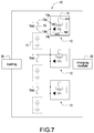
- FIG. 7 is a circuit block diagram of the power storage apparatus according to a second embodiment of the present invention.
- the major difference between the second embodiment shown in FIG. 7 and the first embodiment shown in FIG. 5 is that the number of the at least one battery module 10 of the former is two or more than two.
- the more than two battery modules 10 are connected to form a serial-connected branch, and the serial-connected branch is connected in parallel to the charging module 20 .
- the charging module 20 charges the more than two battery assemblies 12 on the serial-connected branch, the more than two indication elements 141 of the battery modules 10 are not enabled if the more than two protection units 13 of the battery modules 10 are not disconnected (normally conductive).
- the voltage difference value Vab of each protection unit 13 is zero volt, and the voltage difference value Vab is less than the voltage setting value (5 volts) and insufficient to enable the indication element 141 . Accordingly, when the system operator or the system maintainer sees that the LEDs are extinguished, he or she can realize that the operation status of the battery module 10 is normal.
- the indication element 141 corresponding to the disconnected protection unit 13 is driven by the voltage difference value Vab if any one of the more than two protection units 13 of the battery modules 10 is disconnected and the voltage difference value Vab of the disconnected protection unit 13 is greater than the voltage setting value Vset. Accordingly, when the system operator or the system maintainer sees that the LEDs light or blink, he or she can realize that the operation status of the battery module 10 is abnormal, and therefore the battery module 10 shall be replaced or repaired.
- each voltage difference value Vab of each protection unit 13 is still greater than the voltage setting value Vset, and therefore each indication element 141 can be driven to light up by the voltage difference value Vab.
- the voltage setting value Vset may be reduced to correspondingly reduce the charging voltage besides providing the sufficient charging voltage of the charging module 20 as above-mentioned 85 volts.
- the voltage difference value across the two ends of the serial-connected branch is sufficient to drive the corresponding number of the indication elements 141 to light or blink, thereby accurately indicating or rendering the operation status, and particularly to the abnormal status of the battery module 10 for the system operator or the system maintainer.
- FIG. 8 is a circuit block diagram of the power storage apparatus according to a third embodiment of the present invention.
- the major difference between the third embodiment shown in FIG. 8 and the second embodiment shown in FIG. 7 is that the number of the serial-connected branch of the former is two or more than two.
- the two or more than two serial-connected branches are connected in parallel to the charging module 20 .
- the charging module 20 charges the more than four battery assemblies 12 on the serial-connected branches, the more than four indication elements 141 of the battery modules 10 are not enabled if the more than four protection units 13 of the battery modules 10 are not disconnected (normally conductive). At this condition, no excessive abnormal charging current is produced to make any one of the more than four protection units 13 blow during charging.
- the voltage difference value Vab of each protection unit 13 is zero volt, and the voltage difference value Vab is less than the voltage setting value (5 volts) and insufficient to enable the indication element 141 .
- the voltage difference value Vab across the first end 13 a and the second end 13 b of each protection unit 13 is zero volt so that the voltage difference value Vab is less than the voltage setting value (5 volts) and insufficient to enable the indication element 141 .
- the voltage difference value Vab is insufficient to enable the LED to light up. Accordingly, when the system operator or the system maintainer sees that the LEDs are extinguished, he or she can realize that the operation statuses of the four or more than four battery modules 10 are normal.
- the indication element 141 corresponding to the disconnected protection unit 13 is driven by the voltage difference value Vab if any one of the more than four protection units 13 of the battery modules 10 is disconnected and the voltage difference value Vab of the disconnected protection unit 13 is greater than the voltage setting value Vset. Accordingly, when the system operator or the system maintainer sees that the LEDs light or blink, he or she can realize that the operation status of the battery module 10 is abnormal, and therefore the battery module 10 shall be replaced or repaired.
- the worst case scenario for the disconnection of all protection units 13 is considered in the third embodiment shown in FIG. 8 .
- the voltage difference value across the two ends of each serial-connected branch is sufficient to drive the corresponding number of the indication elements 141 to light or blink, thereby accurately indicating or rendering the operation status, and particularly to the abnormal status of the battery module 10 for the system operator or the system maintainer.
- the indication element 141 corresponding to the disconnected protection unit 13 is not enabled by the voltage difference value Vab if any one of the more than four protection units 13 of the battery modules 10 is disconnected and the voltage difference value Vab of the disconnected protection unit 13 is less than the voltage setting value Vset. In other words, the voltage difference value Vab is insufficient to drive the LED to light up.
- the indication element 141 corresponding to the disconnected protection unit 13 is driven by the voltage difference value Vab if any one of the more than four protection units 13 of the battery modules 10 is disconnected and the voltage difference value Vab of the disconnected protection unit 13 is greater than the voltage setting value Vset.
- the charging module 20 fails to effectively charge the battery assemblies 12 on the serial-connected branch but only other non-disconnected serial-connected branches can be charged. After the charging module 20 completes charging the battery assemblies 12 , the voltage value across the disconnected serial-connected branch is gradually reduced if the serial-connected branch cannot be charged by the charging module 20 , and therefore the voltage value across the disconnected serial-connected branch is less than that of any one non-disconnected serial-connected branch.
- a voltage difference value between a voltage across the non-disconnected serial-connected branch and a voltage across the disconnected serial-connected branch is greater than the voltage setting value Vset, it means that at least one indication element 141 can be driven to light or blink.
- the voltage difference value between the voltage across the non-disconnected serial-connected branch and the voltage across the disconnected serial-connected branch is greater than N times the voltage setting value Vset, it means that at least N indication elements 141 can be driven to light or blink, thereby accurately indicating or rendering the operation status, and particularly to the abnormal status of the battery module 10 for the system operator or the system maintainer in the worst case scenario for the disconnection of all protection units 13 .
- FIG. 9 is a flowchart of a method of operating a battery module with an abnormality detection function according to the present invention, and the method includes following steps.
- a battery module is provided, and the battery module includes a battery assembly, a protection unit, and a detection unit (S 11 ).
- the protection unit may be a fuse, and the detection unit may provide the function of a light indication or a sound indication.
- a first current path and a second current path are provided.
- the protection unit and the battery assembly are located on the first current path; the detection unit and the battery assembly are located on the second current path (S 12 ).
- an operation current flows through the second current path; when the protection is not disconnected, the operation current flows through the first current path (S 13 ).
- the protection unit is disconnected and the operation current flows through the second current path, and therefore the operation current makes the detection unit indicate out the abnormal operation by performing the light indication or the sound indication.
- the battery module normally operates, the protection unit is not disconnected and the operation current flows through the first current path, and therefore the operation current fails to make the detection unit work. In other words, the operation current flows through the current path which has the smallest path impedance.
- Simple circuit components installed in each battery module are used to individually protect the battery module and detect an abnormal operation of the battery module.
- the simple protection unit such as the fuse is cooperated with the indication element, such as the LED to provide the detection function, and the indication element is idle and there is almost no power consumption generated from the indication element under the normal operation status of the battery module.
- the concerned information of the voltage difference value of the protection unit acquired by the battery modules can be transmitted to the external monitoring apparatus through the wired manner so that the system operator or the system maintainer can accurately and promptly replace or repair the abnormal battery module after realizing that any one of the battery modules is abnormal.
Landscapes
- Chemical & Material Sciences (AREA)
- Chemical Kinetics & Catalysis (AREA)
- Electrochemistry (AREA)
- General Chemical & Material Sciences (AREA)
- Engineering & Computer Science (AREA)
- Manufacturing & Machinery (AREA)
- Charge And Discharge Circuits For Batteries Or The Like (AREA)
- Secondary Cells (AREA)
Abstract
Description
Claims (18)
Applications Claiming Priority (3)
| Application Number | Priority Date | Filing Date | Title |
|---|---|---|---|
| CN201711181314 | 2017-11-23 | ||
| CN201711181314.6A CN109830764B (en) | 2017-11-23 | 2017-11-23 | Battery module and power storage device with abnormality detection function and operation method thereof |
| CN201711181314.6 | 2017-11-23 |
Publications (2)
| Publication Number | Publication Date |
|---|---|
| US20190157880A1 US20190157880A1 (en) | 2019-05-23 |
| US10862319B2 true US10862319B2 (en) | 2020-12-08 |
Family
ID=66533336
Family Applications (1)
| Application Number | Title | Priority Date | Filing Date |
|---|---|---|---|
| US16/020,336 Active 2038-08-21 US10862319B2 (en) | 2017-11-23 | 2018-06-27 | Battery module with abnormality detection function and power storage apparatus and method of operating the same |
Country Status (2)
| Country | Link |
|---|---|
| US (1) | US10862319B2 (en) |
| CN (1) | CN109830764B (en) |
Families Citing this family (6)
| Publication number | Priority date | Publication date | Assignee | Title |
|---|---|---|---|---|
| CN111880105A (en) * | 2020-07-23 | 2020-11-03 | 国网天津市电力公司 | Detection isolation system for direct-current storage battery pack of transformer substation and isolation method thereof |
| US20240154446A1 (en) * | 2021-03-10 | 2024-05-09 | Honda Motor Co., Ltd. | Electric power device, and control method for same |
| CN114200347B (en) * | 2021-11-30 | 2023-07-18 | 杭州煦达新能源科技有限公司 | Method for detecting abnormal connection of battery cell voltage sampling line in energy storage system |
| KR20240070606A (en) * | 2022-06-17 | 2024-05-21 | 컨템포러리 엠퍼렉스 테크놀로지 씨오., 리미티드 | Safety regulation and control mechanisms, methods, battery systems and electrical devices |
| CN118435420A (en) * | 2022-06-17 | 2024-08-02 | 宁德时代新能源科技股份有限公司 | Safety control mechanism, method, battery system and power-consuming device |
| CN115848148B (en) * | 2022-11-30 | 2024-07-19 | 东风商用车有限公司 | Battery system assembly inspection and balance adjustment device and detection method thereof |
Citations (11)
| Publication number | Priority date | Publication date | Assignee | Title |
|---|---|---|---|---|
| US4041451A (en) * | 1975-05-02 | 1977-08-09 | Konstantin Zarkadas | Circuit for monitoring the operativeness of current-consuming electrical devices |
| US5963019A (en) * | 1996-09-17 | 1999-10-05 | Samsung Electronics Co., Ltd. | Battery pack with battery protection circuit |
| US6331763B1 (en) * | 1998-04-15 | 2001-12-18 | Tyco Electronics Corporation | Devices and methods for protection of rechargeable elements |
| US20040257191A1 (en) * | 2001-08-31 | 2004-12-23 | Rudiger Muller | Fuse component comprising an optical indicator |
| US20060017540A1 (en) * | 2004-07-26 | 2006-01-26 | Smith Jerry L | Fuse blow-out dual LED indicator |
| US20090112496A1 (en) * | 2007-10-30 | 2009-04-30 | Sony Corporation | Battery pack, method of charging secondary battery and battery charger |
| US20100072950A1 (en) * | 2008-09-25 | 2010-03-25 | Yoshinao Tatebayashi | Assembled battery system |
| US20110175699A1 (en) * | 2007-01-05 | 2011-07-21 | Roy Allen Huss | Fuse box system and method |
| US20140293666A1 (en) * | 2011-12-19 | 2014-10-02 | Sma Solar Technology Ag | Circuit arrangement for suppressing an arc occurring over a contact gap of a switching member |
| US8890483B2 (en) * | 2009-07-31 | 2014-11-18 | Panasonic Corporation | Protection circuit, battery pack and charging system |
| US20150035356A1 (en) * | 2012-03-23 | 2015-02-05 | Sanyo Electric Co., Ltd. | Vehicle power source device and vehicle equipped with the power source device |
Family Cites Families (6)
| Publication number | Priority date | Publication date | Assignee | Title |
|---|---|---|---|---|
| JP3291011B2 (en) * | 1990-11-30 | 2002-06-10 | ナルデック株式会社 | Protection device for vehicle electronic devices with solar cells |
| JP4687743B2 (en) * | 2008-05-02 | 2011-05-25 | ソニー株式会社 | Battery pack and control method |
| CN102412564A (en) * | 2010-09-21 | 2012-04-11 | 日隆电子股份有限公司 | Battery pack and protection circuit and method thereof |
| TWI548543B (en) * | 2011-11-07 | 2016-09-11 | 台灣立凱綠能移動股份有限公司 | Abnormal detection system and detection method of battery module |
| JP2013207876A (en) * | 2012-03-28 | 2013-10-07 | Hitachi Ltd | Battery system |
| CN105759166A (en) * | 2016-04-25 | 2016-07-13 | 天津雅迪实业有限公司 | Electric vehicle fuse state detection circuit |
-
2017
- 2017-11-23 CN CN201711181314.6A patent/CN109830764B/en active Active
-
2018
- 2018-06-27 US US16/020,336 patent/US10862319B2/en active Active
Patent Citations (11)
| Publication number | Priority date | Publication date | Assignee | Title |
|---|---|---|---|---|
| US4041451A (en) * | 1975-05-02 | 1977-08-09 | Konstantin Zarkadas | Circuit for monitoring the operativeness of current-consuming electrical devices |
| US5963019A (en) * | 1996-09-17 | 1999-10-05 | Samsung Electronics Co., Ltd. | Battery pack with battery protection circuit |
| US6331763B1 (en) * | 1998-04-15 | 2001-12-18 | Tyco Electronics Corporation | Devices and methods for protection of rechargeable elements |
| US20040257191A1 (en) * | 2001-08-31 | 2004-12-23 | Rudiger Muller | Fuse component comprising an optical indicator |
| US20060017540A1 (en) * | 2004-07-26 | 2006-01-26 | Smith Jerry L | Fuse blow-out dual LED indicator |
| US20110175699A1 (en) * | 2007-01-05 | 2011-07-21 | Roy Allen Huss | Fuse box system and method |
| US20090112496A1 (en) * | 2007-10-30 | 2009-04-30 | Sony Corporation | Battery pack, method of charging secondary battery and battery charger |
| US20100072950A1 (en) * | 2008-09-25 | 2010-03-25 | Yoshinao Tatebayashi | Assembled battery system |
| US8890483B2 (en) * | 2009-07-31 | 2014-11-18 | Panasonic Corporation | Protection circuit, battery pack and charging system |
| US20140293666A1 (en) * | 2011-12-19 | 2014-10-02 | Sma Solar Technology Ag | Circuit arrangement for suppressing an arc occurring over a contact gap of a switching member |
| US20150035356A1 (en) * | 2012-03-23 | 2015-02-05 | Sanyo Electric Co., Ltd. | Vehicle power source device and vehicle equipped with the power source device |
Also Published As
| Publication number | Publication date |
|---|---|
| CN109830764B (en) | 2021-08-06 |
| CN109830764A (en) | 2019-05-31 |
| US20190157880A1 (en) | 2019-05-23 |
Similar Documents
| Publication | Publication Date | Title |
|---|---|---|
| US10862319B2 (en) | Battery module with abnormality detection function and power storage apparatus and method of operating the same | |
| US6051955A (en) | Protection circuit and battery unit | |
| US20100187908A1 (en) | Maintenance Bypass Device | |
| KR102044598B1 (en) | Apparatus and method for detect malfunction of battery pack | |
| US20160301232A1 (en) | Battery unit, overcurrent control method, and computer program for the same | |
| US7112896B2 (en) | Power system with load matrix | |
| CN203798939U (en) | Line sequence detection circuit | |
| US8953291B2 (en) | Reversal connection protecting circuit | |
| KR102554673B1 (en) | Battery pack | |
| US20200136427A1 (en) | Electronic circuit for redundant supply of an electric load | |
| JPH05137278A (en) | Electric power supply system | |
| CN111123168B (en) | Fault detection circuit for battery pack connection line | |
| US20210223843A1 (en) | Device, cabinet, and method for preventing power outage of entire cabinet | |
| US10412826B2 (en) | Circuit board and method for manufacturing the same, terminal test device | |
| TW201743529A (en) | Power supply relay unit | |
| CN112630648B (en) | High Bian Binglian contactor adhesion detection circuit of battery system | |
| US20100148583A1 (en) | Method and device for providing battery polarity protection for uninterruptible power supply | |
| CN105591438B (en) | Micro-power battery pack and micro photovoltaic inverter device with safety control | |
| CN113193646B (en) | Power supply device, method and system | |
| TWI632387B (en) | Battery module with abnormality detection function and power storage apparatus and method of controlling the same | |
| US6420850B1 (en) | Telecommunication power distribution systems and apparatuses and methods of supplying power to a telecommunication device | |
| KR102207418B1 (en) | Light emitting diode apparatus fault diagnosis rpoviding easy maintenance | |
| CN220855624U (en) | Input combining module, server power supply and server | |
| CN221328611U (en) | Protection circuit, power supply equipment and power supply system | |
| KR100933744B1 (en) | Dual fuse unit |
Legal Events
| Date | Code | Title | Description |
|---|---|---|---|
| FEPP | Fee payment procedure |
Free format text: ENTITY STATUS SET TO UNDISCOUNTED (ORIGINAL EVENT CODE: BIG.); ENTITY STATUS OF PATENT OWNER: LARGE ENTITY |
|
| AS | Assignment |
Owner name: DELTA ELECTRONICS, INC., TAIWAN Free format text: ASSIGNMENT OF ASSIGNORS INTEREST;ASSIGNORS:LAI, YUAN-FANG;CHANG, YING-SUNG;SIGNING DATES FROM 20180619 TO 20180620;REEL/FRAME:046269/0171 |
|
| STPP | Information on status: patent application and granting procedure in general |
Free format text: DOCKETED NEW CASE - READY FOR EXAMINATION |
|
| STPP | Information on status: patent application and granting procedure in general |
Free format text: NON FINAL ACTION MAILED |
|
| STPP | Information on status: patent application and granting procedure in general |
Free format text: RESPONSE TO NON-FINAL OFFICE ACTION ENTERED AND FORWARDED TO EXAMINER |
|
| STPP | Information on status: patent application and granting procedure in general |
Free format text: FINAL REJECTION MAILED |
|
| STPP | Information on status: patent application and granting procedure in general |
Free format text: RESPONSE AFTER FINAL ACTION FORWARDED TO EXAMINER |
|
| STCF | Information on status: patent grant |
Free format text: PATENTED CASE |
|
| MAFP | Maintenance fee payment |
Free format text: PAYMENT OF MAINTENANCE FEE, 4TH YEAR, LARGE ENTITY (ORIGINAL EVENT CODE: M1551); ENTITY STATUS OF PATENT OWNER: LARGE ENTITY Year of fee payment: 4 |