US10862282B2 - Protector for wire harness, and method for manufacturing wire harness - Google Patents
Protector for wire harness, and method for manufacturing wire harness Download PDFInfo
- Publication number
- US10862282B2 US10862282B2 US15/994,622 US201815994622A US10862282B2 US 10862282 B2 US10862282 B2 US 10862282B2 US 201815994622 A US201815994622 A US 201815994622A US 10862282 B2 US10862282 B2 US 10862282B2
- Authority
- US
- United States
- Prior art keywords
- path
- electric wire
- protector
- body portion
- holding
- Prior art date
- Legal status (The legal status is an assumption and is not a legal conclusion. Google has not performed a legal analysis and makes no representation as to the accuracy of the status listed.)
- Active, expires
Links
Images


Classifications
-
- H—ELECTRICITY
- H02—GENERATION; CONVERSION OR DISTRIBUTION OF ELECTRIC POWER
- H02G—INSTALLATION OF ELECTRIC CABLES OR LINES, OR OF COMBINED OPTICAL AND ELECTRIC CABLES OR LINES
- H02G3/00—Installations of electric cables or lines or protective tubing therefor in or on buildings, equivalent structures or vehicles
- H02G3/02—Details
- H02G3/04—Protective tubing or conduits, e.g. cable ladders or cable troughs
- H02G3/0437—Channels
-
- B—PERFORMING OPERATIONS; TRANSPORTING
- B60—VEHICLES IN GENERAL
- B60R—VEHICLES, VEHICLE FITTINGS, OR VEHICLE PARTS, NOT OTHERWISE PROVIDED FOR
- B60R16/00—Electric or fluid circuits specially adapted for vehicles and not otherwise provided for; Arrangement of elements of electric or fluid circuits specially adapted for vehicles and not otherwise provided for
- B60R16/02—Electric or fluid circuits specially adapted for vehicles and not otherwise provided for; Arrangement of elements of electric or fluid circuits specially adapted for vehicles and not otherwise provided for electric constitutive elements
- B60R16/0207—Wire harnesses
- B60R16/0215—Protecting, fastening and routing means therefor
-
- H—ELECTRICITY
- H02—GENERATION; CONVERSION OR DISTRIBUTION OF ELECTRIC POWER
- H02G—INSTALLATION OF ELECTRIC CABLES OR LINES, OR OF COMBINED OPTICAL AND ELECTRIC CABLES OR LINES
- H02G3/00—Installations of electric cables or lines or protective tubing therefor in or on buildings, equivalent structures or vehicles
- H02G3/02—Details
- H02G3/04—Protective tubing or conduits, e.g. cable ladders or cable troughs
- H02G3/0406—Details thereof
- H02G3/0418—Covers or lids; Their fastenings
-
- H—ELECTRICITY
- H01—ELECTRIC ELEMENTS
- H01B—CABLES; CONDUCTORS; INSULATORS; SELECTION OF MATERIALS FOR THEIR CONDUCTIVE, INSULATING OR DIELECTRIC PROPERTIES
- H01B7/00—Insulated conductors or cables characterised by their form
- H01B7/0045—Cable-harnesses
Definitions
- the present invention relates to a protector for a wire harness and a method for manufacturing the wire harness.
- protector for a wire harness which defines a path (cavity or space) inside thereof, capable of housing electric wires configuring the wire harness.
- the protector for the wire harness is generally used as a fixing tool when the wire harness is routed in a vehicle body of an automobile or the like while protecting the electric wires housed inside thereof.
- the protector for the wire harness is simply referred to as “protector”.
- one of conventional protectors includes a tub-shaped protector body having a bottom wall and two side walls, and a cover for covering an opening portion at an upper end side of the protector body.
- the conventional protector houses the electric wires by mounting and fixing the cover to the protector body.
- the wire harness is manufactured by a series of manufacturing steps containing housing the electric wires in the protector. More particularly, the wire harness is generally manufactured by mounting a plurality of electric wires and various routing members (for example, a protector, a grommet and a clamp or the like) mounted to the electric wires on dedicated workbenches (that is, a jig plate or the like). However, since there are a variety of the electric wires and the routing members configuring the wire harness, the wire harness is generally manufactured by a plurality of manufacturing steps on a plurality of workbenches.
- the cover is generally mounted to the protector body of the conventional protector before the electric wires are moved. In other words, mounting the cover to the protector body (housing the electric wires in the protector) is generally finished on each workbench.
- the number of the protectors mounted to the wire harnesses is also increased.
- the number of the protectors is as small as possible.
- the present invention has been made in view of the above circumstances, and an object thereof is to provide a protector for a wire harness which can reduce the number of the protectors required for the wire harnesses, and a method for manufacturing the wire harness used such a protector.
- the protector for the wire harness according to the present invention is characterized by the following (1) to (4).
- a protector for a wire harness which is a protector for a wire harness including a body portion for defining a plurality of paths through which electric wires configuring the wire harness is capable of passing, an electric wire holding portion for holding the electric wire, and a cover portion for covering the body portion and the electric wire holding portion, characterized in that:
- the body portion contains a first path and a second path, as the plurality of the paths, which are partitioned by a partition wall, and also includes a first side wall opposite to the partition wall with the first path interposed therebetween and a second side wall opposite to the partition wall with the second path interposed therebetween, and
- the electric wire holding portion includes a holding piece which is capable of being disposed so as to pass through an upper side of the first path and extend toward the partition wall from the first side wall, an engaging piece which is capable of being disposed so as to pass through a lower side of the second path and extend toward the second side wall from the partition wall, and an intermediate piece which connects the holding piece and the engaging piece, and is fixable to the body portion.
- the partition wall includes a communication portion which communicates the first path and the second path
- the intermediate piece is capable of being disposed so as to block the communication portion.
- the body portion includes a third path into which the first path and the second path are merged
- the partition wall includes the communication portion at a position away from a merging position between the first path and the second path.
- the electric wire holding portion is configured such that the holding piece is rotatably connected to the first side wall via a hinge portion and the engaging piece includes an engaging portion whose engaging piece is engageable with the second side wall, and
- the body portion includes an engaged portion corresponding to the engaging portion.
- the first electric wire group housed in the first path can be held by the holding piece of the electric holding portion passing through the upper side of the first path (a side close to the cover portion) if the electric wire holding portion is fixed to the protector. Therefore, different from the conventional protector, the electric wire group housed in the first path can be held without mounting the cover portion to the body portion.
- the second path is kept in a state capable of housing the electric wires.
- the wire harness can be moved from one workbench to another workbench in a manufacturing process without mounting the cover portion to the body portion (that is, without finishing housing the electric wires in the protector).
- the second electric wire group housed in the second path can be held by the cover portion if the cover portion is mounted and fixed to the body portion.
- the protector for the wire harness having the configuration, it is not necessary to finish mounting the protector to each workbench. Therefore, compared to a case where mounting the protector to each workbench is finished like the conventional protector, the number of the protectors required for the wire harnesses can be reduced.
- an electric wire holding portion for holding the electric wires housed in the first path and an electric wire holding portion for holding the electric wires housed in the second path are regarded as separate members which are independent from each other, although it is not necessary to finish mounting the protector to each workbench, the engaging portions for fixing to the body portion are provided on the electric wire holding portions respectively, and the engaged portions corresponding to the engaging portions are provided on the body portion. Consequently, compared to the protector for the wire harness having the configuration, the number of the engaging portions and the engaged portions are increased when the electric wire holding portions are regarded as a plurality of separate members.
- the protector for the wire harness having the configuration has an advantage that the volumes of the paths in the protector can be used maximally.
- the protector for the wire harness having the configuration of above-mentioned (2) a part of the electric wire holding portion (the intermediate piece) is disposed so as to block a cut out portion (the communication portion) formed in the partition wall, and the intermediate piece becomes a part of the partition wall. Therefore, compared to a case where the communication portion is not present in the partition wall and the entire intermediate piece is disposed in the path (the first path or the second path), the projection amount of the intermediate piece projected to the paths becomes small, and the volumes of the paths are increased. As a result, the number and kinds of the electric wires capable of being housed in the paths can be increased. Consequently, according to the protector for the wire harness having the configuration, the volumes of the paths in the protector can be used maximally.
- the protector for the wire harness having the configuration of above-mentioned (3), even in a case where an electric wire (that is, an electric wire which is not directed to the third path) of the electric wires housed in the protector from the first path to the second path through the merging position is present, the electric wire will not enter the communication portion since the electric wire contacts with the partition wall adjacent to the merging position. Therefore, the electric wire will not be interposed between the electric wire holding portion (the intermediate piece or the like) and the body portion. Consequently, compared to a case where the communication portion at a position adjacent to the merging position is present (in other words, the intermediate piece of the electric wire holding portion at the position adjacent to the merging position is present), it is possible to prevent damage of the electric wire, or the like.
- the protector for the wire harness having the configuration of above-mentioned (4), the electric wire holding portion can be easily fixed to the body portion by rotating the electric wire holding portion around the hinge portion. Therefore, compared to a case where the body portion and the electric wire holding portion are separate members separated from each other, the workability of the step of housing the electric wires in the first path can be improved.
- the method for manufacturing the wire harness according to the present invention is characterized by the following (5) to (6).
- a method for manufacturing a wire harness which is a method for manufacturing a wire harness including a plurality of electric wires and a protector defining a plurality of paths inside, characterized in that:
- the protector includes:
- the method for manufacturing the wire harness contains:
- the third step contains a step of mounting a routing component to the second electric wire group, and a step of disposing the second electric wire group in the second path such that at least a part of the routing component is positioned inside the protector.
- the electric wire holding portion is fixed to the protector, and thereby the first electric wire group housed in the first path can be held by the holding piece of the electric holding portion passing through the upper side of the first path (a side close to the cover portion). Therefore, different from the conventional protector, the electric wire group housed in the first path can be held without mounting the cover portion to the body portion.
- the second path is kept in a state capable of housing the electric wires.
- the wire harness can be moved from one workbench to another workbench in a manufacturing process without mounting the cover portion to the body portion (that is, without finishing housing the electric wires in the protector).
- the cover portion is mounted and fixed to the body portion, and thereby the second electric wire group housed in the second path can be held by the cover portion.
- the method for manufacturing the wire harness having the configuration it is not necessary to finish mounting the protector to each workbench. Therefore, compared to a case where mounting the protector to each workbench is finished by using the conventional protector, the number of the protectors required for the wire harnesses can be reduced in the method for manufacturing the wire harness having the configuration.
- the routing component for example, a grommet and a clamp, and a tape wound on the electric wires for fixing the grommet and the clamp to the electric wires
- the routing component is positioned inside the protector. Therefore, compared to a case where the entire routing component is exposed outside the protector, the damage of the routing component can be reduced.
- the routing component along with the protector can be fixed to the vehicle or the like. Besides, the workability of manufacturing the wire harness is improved by integrally handling the routing component and the protector.
- the protector for the wire harness the number of which required for a wire harness can be reduced, and the method for manufacturing the wire harness by using such a protector can be provided.
- FIG. 1 is a perspective view in a case where an electric wire holding portion is disposed at a retreat position in a protector for a wire harness according to an embodiment.
- FIG. 2 is a perspective view in a case where the electric wire holding portion is disposed at an attachment position in the protector for the wire harness according to the embodiment.
- FIG. 3 is a cross-sectional view along a line A-A in FIG. 2 .
- FIG. 4 is a plan view of the wire harness whose electric wire is housed in a body portion of the protector.
- FIG. 5 is a schematic view for describing a method for manufacturing the wire harness, and a cross-sectional view in a direction orthogonal to an axial direction of a path of an electric wire group at a point of time before the electric wire group is housed in the protector.
- FIG. 6 is a schematic view for describing the method for manufacturing the wire harness, and a cross-sectional view in the direction orthogonal to the axial direction of the path of the electric wire group at a point of time when a first electric wire is housed in the body portion of the protector.
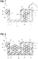
- FIG. 7 is a schematic view for describing the method for manufacturing the wire harness, and a cross-sectional view in the direction orthogonal to the axial direction of the path of the electric wire group at a point of time when the electric holding portion is fixed to the body portion of the protector.
- FIG. 8 is a schematic view for describing the method for manufacturing the wire harness, and a cross-sectional view in the direction orthogonal to the axial direction of the path of the electric wire group at a point of time when a first electric wire and a second electric wire are housed in the body portion of the protector.
- FIG. 9 is a schematic view for describing the method for manufacturing the wire harness, and a cross-sectional view in the direction orthogonal to the axial direction of the path of the electric wire group at a point of time when a cover portion is attached to the body portion of the protector.
- FIG. 10 is a cross-sectional view in a direction orthogonal to an axial direction of a path of an electric wire group of a protector according to Modification 1.
- FIG. 11 is a cross-sectional view in a direction orthogonal to an axial direction of a path of an electric wire group of a protector according to Modification 2.
- a protector for a wire harness includes a body portion 11 , an electric holding portion 12 and a cover portion 13 .
- the body portion 11 , the electric holding portion 12 and the cover portion 13 are formed from a synthetic resin.
- the protector 10 is mounted to electric wire groups bundling a plurality of electric wires to configure the wire harness.
- the protector 10 is, for example, fixed to a predetermined position of a vehicle. Accordingly, the wire harness is routed in a vehicle body.
- the body portion 11 defines a plurality of paths through which the electric wires configuring the wire harness can pass.
- the body portion 11 includes a bottom plate portion 20 , a first side wall 21 , a second side wall 22 and a partition wall 23 .
- the bottom plate portion 20 forms in a long plate shape, and the first side wall 21 and the second side wall 22 are erected upward from a side edge of the bottom plate portion 20 .
- the partition wall 23 is erected on a substantially central portion in a width direction of the bottom plate portion 20 , and the first side wall 21 and the second side wall 22 are disposed in parallel.
- the partition wall 23 extends partway from a side of one end 11 a to the other end 11 b of the body portion 11 along a longitudinal direction of the bottom plate portion 20 .
- the body portion 11 includes, as the plurality of the paths through which the electric wires pass, a first path 31 , a second path 32 and a third path 33 (see FIG. 4 for the situation that the electric wires are housed in each of the paths).
- the first path 31 and the second path 32 are adjacent to each other, and the third path 33 is provided at a position where the first path 31 and the second path 32 are merged such that the first path 31 and the second path 32 are connected in the longitudinal direction of the body portion 11 .
- the first path 31 and the second path 32 are partitioned by the partition wall 23 formed on a substantially central position in the width direction of the body portion 11 . Accordingly, the first side wall 21 is disposed at a position opposite to the partition wall 23 with the first path 31 interposed therebetween, and the second side wall 22 is disposed at a position opposite to the partition wall 23 with the second path 32 interposed therebetween. Further, the partition wall 23 includes a communication portion 24 .
- the communication portion 24 is a part where a wall portion of the partition wall 23 is cut out (the wall portion is not present), and a part where the first path 31 and the second path 32 are communicated with each other through the communication portion 24 .
- the communication portion 24 is formed at a position away from a merging position G between the first path 31 and the second path 32 and near an end portion at a side of the third path 33 .
- the electric wire holding portion 12 is a member for holding the electric wires, and includes a holding piece 41 , an engaging piece 42 and an intermediate piece 43 .
- the electric wire holding portion 12 is provided integrally (via a hinge portion 44 to be described later) with the body portion 11 , and is fixable to the body portion 11 in a state of holding the electric wires.
- An end portion of the holding piece 41 of the electric wire holding portion 12 is rotatably connected to an upper edge portion of the first side wall 21 of the body portion 11 via the hinge portion 44 .
- the electric wire holding portion 12 includes the holding piece 41 , the intermediate piece 43 and the engaging piece 42 in order from a side where the electric wire holding portion 12 is connected with the first side wall 21 by the hinge portion 44 .
- the electric wire holding portion 12 is configured such that the holding piece 41 and the engaging piece 42 are connected by the intermediate piece 43 .
- the electric wire holding portion 12 is housed in the body portion 11 by rotating around the hinge portion 44 .
- the electric wire holding portion 12 is movable from a retreat position outside the body portion 11 (a position shown in FIG. 1 ) to an attachment position housed in the body portion 11 (a position shown in FIGS. 2 and 3 ) by rotating around the hinge portion 44 .
- the holding piece 41 is disposed so as to extend toward an upper end of the partition wall 23 from an upper end of the first side wall 21 in the attachment position (the position shown in FIGS. 2 and 3 ). Accordingly, an upper side of the first path 31 formed between the first side wall 21 and the partition wall 23 is covered by the holding piece 41 of the electric wire holding portion 12 .
- the engaging piece 42 is disposed so as to extend toward from a lower end of the second side wall 22 from a lower end of the partition wall 23 in the attachment position (the position shown in FIGS. 2 and 3 ). Accordingly, the engaging piece 42 passes a lower side of the second path 32 formed between the second side wall 22 and the partition wall 23 .
- the intermediate piece 43 is disposed so as to block the communication portion 24 of the partition wall 23 in the attachment position (the position shown in FIGS. 2 and 3 ).
- the engaging piece 42 includes an engaging portion 45 on an end portion of the engaging piece 42 at a side opposite to the intermediate piece 43 .
- the engaging portion 45 extends toward an upper end side from the engaging piece 42 along an inner surface of the second side wall 22 (also see FIG. 3 ).
- the engaging portion 45 includes a folded portion 46 .
- the folded portion 46 extends so as to be folded toward an outer surface side of the second side wall 22 on an upper end of the second side wall 22 in the attachment position (the position shown in FIGS. 2 and 3 ).
- An engaging claw 47 is formed on the folded portion 46 .
- the body portion 11 includes an electric wire holding portion 51 different from the electric wire holding portion 12 at a side of the third path 33 .
- the electric wire holding portion 51 is provided integrally (via a hinge portion 52 to be described later) with the body portion 11 , and is fixable to the body portion 11 in a state of being stretched from the upper end of the first side wall 21 to the upper end of the second side wall 22 so as to cover an upper side of the third path 33 in the attachment position (the position shown in FIG. 2 ).
- One end of the electric wire holding portion 51 is rotatably connected to the upper edge portion of the first side wall 21 of the body portion 11 via the hinge portion 52 .
- the electric wire holding portion 51 is housed in the body portion 11 by rotating around the hinge portion 52 .
- the electric wire holding portion 51 is movable from the retreat position outside the body portion 11 (the position shown in FIG. 1 ) to the attachment position housed in the body portion 11 (the position shown in FIG. 2 ) by rotating around the hinge portion 52 .
- the electric wire holding portion 51 includes an engaging portion 53 on the other end side opposite to one end having the hinge portion 52 .
- the engaging portion 53 includes a folded portion 54 extending so as to be folded toward the outer surface side of the second side wall 22 in the attachment position (the position shown in FIG. 2 ), and an engaging claw 55 is formed on the folded portion 54 .
- the first side wall 21 configuring the body portion 11 includes an engaging recess portion 25 , to which the engaging portion 45 of the electric wire holding portion 12 is fitted, and an engaging recess portion 27 , to which the electric wire holding portion 51 is fitted, on the upper end thereof. Further, the body portion 11 includes an engaged portion 26 corresponding to the engaging portion 45 of the electric wire holding portion 12 at a side of an outer surface of the first side wall 21 (also see FIG. 3 ), and an engaged portion 28 corresponding to the engaging portion 53 of the electric wire holding portion 51 on the outer surface of the first side wall 21 .
- Both ends of the engaged portions 26 , 28 are respectively fixed to the outer surface of the first side wall 21 , and the engaged portions 26 , 28 are respectively disposed with gaps with respect to the outer surface of the first side wall 21 .
- the engaging claw 47 is engaged with the engaged portion 26 by inserting the engaging portion 45 of the electric wire holding portion 12 to the gap between the engaged portion 26 and the outer surface of the first side wall 21 .
- the engaging claw 55 is engaged with the engaged portion 28 by inserting the engaging portion 53 of the electric wire holding portion 51 to the gap between the engaged portion 28 and the outer surface of the first side wall 21 .
- the cover portion 13 is attached to an upper portion of the body portion 11 , and is a member for covering the electric wire holding portion 12 and the electric wire holding portion 51 .
- the cover portion 13 includes an upper plate portion 60 , a first side wall 61 and a second side wall 62 .
- the upper plate portion 60 is formed in a long plate shape, and the first side wall 61 and the second side wall 62 extends downward from a side edge of the upper plate portion 60 .
- the cover portion 13 is formed such that an interval between the inner surface sides of the first side wall 61 and the second side wall 62 is slightly larger than a width dimension of the body portion 11 .
- the upper portion of the body portion 11 enters between the first side wall 61 and the second side wall 62 of the cover portion 13 by covering the cover portion 13 on the upper portion of the body portion 11 . Accordingly, the cover portion 13 is attached to the upper portion of the body portion 11 , and the upper sides of the first path 31 , the second path 32 and the third path 33 of the body portion 11 are blocked by the cover portion 13 (also see the method for manufacturing the wire harness to be described later).
- FIG. 4 is a schematic view of the protector 10 housed in the plurality of the electric wires 1 viewed from above, and illustration of the cover portion 13 is omitted for convenience.
- the wire harness WH includes the protector 10 and the electric wires 1 held in the protector 10 .
- the plurality of the electric wires 1 held in the protector 10 includes a first electric wire group 71 , a second electric wire group 72 and a third electric wire group 73 .
- the third electric wire group 73 is an electric wire group into which the first electric wire group 71 and the second electric wire group 72 are merged. In other words, the first electric wire group 71 and the second electric wire group 72 are branched from the third electric wire group 73 .
- At least one electric wire 1 a of the electric wires 1 is wired over the first electric wire group 71 and the second electric wire group 72 so as to be directed to the second path 32 from the first path 31 through the merging position G (that is, so as not to be directed to the third path 33 ).
- the second electric wire group 72 includes a routing component 75 .
- a grommet 76 fitted to a panel of the vehicle body, or the like, and a tape 77 for fixing the grommet 76 to the second electric wire group 72 , as the routing component 75 , are provided on the second electric wire group 72 .
- the grommet 76 is fixed to the second electric wire group 72 by winding the tape 77 over a part of the grommet 76 and the second electric wire group 72 .
- the first electric wire group 71 which is a part of the electric wires 1 is housed in the first path 31 of the body portion 11 and the second electric wire group 72 which is the other part of the electric wires 1 is housed in the second path 32 of the body portion 11 .
- the third electric wire group 73 of the electric wires 1 is housed in the third path 33 of the body portion 11 .
- a part of the electric wire 1 a wired over the first electric wire group 71 and the second electric wire group 72 is housed in the body portion 11 so as to be directed to the second path 32 from the first path 31 through the merging position G.
- the first electric wire group 71 of the electric wires 1 housed in the body portion 11 of the protector 10 is held by the holding piece 41 of the electric wire holding portion 12
- the third electric wire group 73 is held by the electric wire holding portion 51 .
- the first electric wire group 71 , the second electric wire group 72 and the third electric wire group 73 housed in the body portion 11 are held by attaching the cover portion 13 to the body portion 11 of the protector 10 .
- the routing component 75 mounted to the second electric wire group 72 is disposed such that a winding portion of the tape 77 which is a part of the routing component 75 is positioned inside the protector 10 .
- the body portion 11 of the protector 10 is disposed at a predetermined position on a jig plate, and the electric wire holding portion 12 (and the electric wire holding portion 51 which is not shown) is disposed at the retreat position.
- the first electric wire group 71 is housed in the first path 31 of the body portion 11 (the first step).
- the third electric wire group 73 is housed in the third path 33 (not shown) of the body portion 11 .
- the electric wire holding portion 12 is moved to the attachment position in the body portion 11 by rotating toward the inner side of the body portion 11 (in a direction of arrow B in FIG. 7 ), and the electric wire holding portion 12 is fixed to the body portion 11 by engaging the engaging claw 47 of the engaging portion 45 with the engaged portion 26 . Accordingly, the upper side of the first path 31 is covered by the holding piece 41 of the electric wire holding portion 12 , and the first electric wire group 71 housed in the first path 31 is held in the body portion 11 (the second step).
- the electric wire holding portion 51 (not shown) is rotated and moved to the attachment position, and the electric wire holding portion 51 is fixed to the body portion 11 by engaging the engaging claw 66 of the engaging portion 53 with the engaged portion 28 . Accordingly, the upper side of the third path 33 is covered by the electric wire holding portion 51 , and the third electric wire group 73 housed in the third path 33 is held in the body portion 11 .
- the body portion 11 of the protector 10 is removed from the jig plate, and the body portion 11 is disposed on another workbench where the next steps are performed.
- the routing component 75 (the grommet 76 and the tape 77 ) is attached to the second electric wire group 72 .
- the grommet 76 is disposed at a predetermined position through the second electric wire group 72
- the tape 77 is wound over the part of the grommet 76 and the second electric wire group 72 .
- the routing component 75 (the grommet 76 and the tape 77 ) is fixed to a predetermined position of the second electric wire group 72 .
- the second electric wire group 72 to which the routing component 75 is mounted is housed in the second path 32 of the body portion 11 (the third step).
- the winding portion of the tape 77 which is a part of the routing component 75 is disposed in the second path 32 (also see FIG. 4 ).
- the cover portion 13 is fixed to the body portion 11 such that the cover portion 13 is moved from above the body portion 11 to the body portion 11 (in a direction of arrow C in FIG. 9 ), the cover portion 13 covers on the upper portion of the body portion 11 , and the body portion 11 and the electric wire holding portion 12 (and the electric wire holding portion 51 which is not shown) are covered. Accordingly, the cover portion 13 is attached to the upper portion of the body portion 11 , and the upper sides of the first path 31 , the second path 32 and the third path 33 of the body portion 11 are blocked by the cover portion 13 (the forth step).
- the wire harness WH whose protector 10 is attached to the electric wires 1 including the first electric wire group 71 , the second electric wire group 72 and the third electric wire group 73 can be manufactured.
- the protector 10 of the present embodiment after a part of the plurality of the electric wires 1 (the first electric wire group 71 ) forming the wire harness WH are housed in the first path 31 of the protector 10 , the first electric wire group 71 housed in the first path 31 can be held by the holding piece 41 of the electric holding portion 12 passing through the upper side of the first path 31 if the electric wire holding portion 12 is fixed to the body portion 11 of the protector 10 . Therefore, different from the conventional protector, the first electric wire group 71 housed in the first path 31 can be held without mounting the cover portion 13 to the body portion 11 .
- the second path 32 is kept in a state capable of housing the electric wires (the second electric wire group 72 ).
- the wire harness WH can be moved from one workbench to another workbench in a manufacturing process without fixing the cover portion 13 to the body portion 11 (that is, without finishing housing the electric wires 1 to the protector 10 ).
- the cover portion 13 is mounted and fixed to the body portion 11 , and thereby the second electric wire group 72 housed in the second path 32 can be held by the cover portion 13 .
- the protector 10 of the embodiment it is not necessary to finish mounting the protector 10 on each workbench. Therefore, compared to a case where mounting the protector to each workbench is finished like the conventional protector, the number of the protectors 10 required for the wire harnesses WH can be reduced.
- a part of the electric wire holding portion (the intermediate piece 43 ) is disposed so as to block the cut out portion (the communication portion 24 ) formed in the partition wall 23 , and the intermediate piece 43 becomes a part of the partition wall 23 . Therefore, compared to a case where the communication portion 24 is not present in the partition wall 23 and the entire intermediate piece 43 is disposed in the path (the first path 31 or the second path 32 ), the projection amount of the intermediate piece 43 projected to the paths 31 , 32 becomes small, and the volumes of the paths 31 , 32 are increased. Consequently, according to the protector 10 , the volumes of the paths in the protector 10 can be used maximally.
- the protector 10 of the embodiment even in a case where the electric wire 1 a from the first path 31 to the second path 32 through the merging position G is present in the electric wires 1 housed in the protector 10 , the electric wire 1 a will not enter the communication portion 24 since the electric wire 1 a contacts with the partition wall 23 adjacent to the merging position G. Therefore, the electric wire 1 a will be not interposed between the electric wire holding portion 12 (the intermediate piece 43 or the like) and the body portion 11 .
- the electric wire holding portion 12 can be easily fixed to the body portion 11 by rotating the electric wire holding portion 12 around the hinge portion 44 . Therefore, compared to a case where the body portion 11 and the electric wire holding portion 12 are separate members which are separated, the workability of the step of housing the electric wires 1 in the first path 31 can be improved.
- the electric wire holding portion 12 is fixed to the protector 10 , and thereby the first electric wire group 71 housed in the first path 31 can be held by the holding piece 41 of the electric wire holding portion 12 passing through the upper side of the first path 31 . Therefore, different from the conventional protector, the first electric wire group 71 housed in the first path 31 can be held without mounting the cover portion 13 to the body portion 11 .
- the second path 32 is kept in a state capable of housing the electric wires (the second electric wire group 72 ).
- the wire harness WH can be moved from one workbench to another workbench in a manufacturing process without mounting the cover 13 to the body portion 11 (that is, without finishing housing the electric wires 1 to the protector 10 ).
- the cover portion 13 is mounted and fixed to the body portion 11 , and thereby the second electric wire group 72 housed in the second path 32 can be held by the cover portion 13 .
- the wire harness WH can be manufactured in a state where the number of the protectors 10 required for the wire harnesses WH can be reduced.
- the tape 77 which is at least a part of the routing component 75 including the grommet 76 and the tape 77 is positioned inside the protector 10 . Therefore, compared to a case where the entire routing component 75 is exposed outside the protector 10 , the damage of the routing component 75 can be reduced. Further, when the wire harness WH is routed in the vehicle or the like, the routing component 75 along with the protector 10 can be fixed to the vehicle or the like. Besides, the workability of manufacturing the wire harness WH is improved by integrally handling the routing component 75 and the protector 10 .
- the routing component 75 is not limited to the grommet 76 or the tape 77 , and may be the clamp fixed to the electric wires 1 , or the like.
- a protector 10 A according to Modification 1 includes a body portion 11 A on which three paths 81 to 83 are disposed in parallel. Further, the protector 10 A includes an electric wire holding portion 12 A whose central portion projects downward and is formed in a recessed shape.
- the protector 10 A In the protector 10 A according to Modification 1, after electric wire groups are housed in the paths 81 , 83 at two sides of the body portion 11 A, the electric wire groups housed in the paths 81 , 83 can be held in the body portion 11 A by fixing the electric wire holding portion 12 A to the body portion 11 A. Therefore, in a state of holding the electric wire groups housed in the paths 81 , 83 , the wire harness WH can be moved from one workbench to another workbench in a manufacturing process without fixing the cover portion 13 to the body portion 11 A. Further, after holding the electric wire groups in the paths 81 , 83 , the electric wire group is housed in the path 82 and the cover portion 13 is attached to the body portion 11 A, and thereby the electric wire group housed in the path 82 can be held.
- a protector 10 B according to Modification 2 includes a body portion 11 B on which three paths 91 to 93 are disposed in parallel. Further, the protector 10 B includes an electric wire holding portion 12 B whose opposite side to the hinge portion 44 projects downward and is formed in a recessed shape.
- the protector 10 B In the protector 10 B according to Modification 2, after electric wire groups are housed in the path 91 at a side of the hinge portion 44 and the central path 92 of the body portion 11 B, the electric wire groups housed in the paths 91 , 92 can be held in the body portion 11 B by fixing the electric wire holding portion 12 B to the body portion 11 B. Therefore, in a state of holding the electric wire groups housed in the paths 91 , 92 , the wire harness WH can be moved from one workbench to another workbench in a manufacturing process without fixing the cover portion 13 to the body portion 11 B. Further, after holding the electric wire groups in the paths 91 , 92 , the electric wire group is housed in the path 93 and the cover portion 13 is attached to the body portion 11 B, and thereby the electric wire group housed in the path 93 can be held.
- the present invention is not limited to the above-mentioned embodiments, and various modifications can be adopted within the scope of the present invention.
- the present invention is not limited to the above-mentioned embodiments, but may be appropriately modified, improved, or the like.
- materials, shapes, dimensions, numbers, disposition locations, or the like of the constituent elements in the above-mentioned embodiments are optional as long as the present invention can be achieved, and are not limited.
- the protector 10 includes the body portion 11 and the cover portion 13 which are respectively separated.
- the protector 10 may be configured so as to have an integrated configuration that the body portion 11 and the cover portion 13 are connected by a hinge or the like.
- the body portion 11 and the electric wire holding portion 12 are connected by the hinge portion 44 .
- the electric wire holding portion 12 may be configured as a separate member separated from the body portion 11 .
- the engaging portion and the engaged portion for engaging the holding piece 41 of the electric wire holding portion 12 with the first side wall 21 of the body portion 11 may be provided on the holding piece 41 and the first side wall 21 .
- a protector ( 10 ) for a wire harness including a body portion ( 11 ) having a plurality of paths through which electric wires ( 1 ) of the wire harness (WH) is capable of passing, an electric wire holding portion ( 12 ) for holding the electric wires, and a cover portion ( 13 ) for covering the body portion ( 11 ) and the electric wire holding portion ( 12 ), wherein
- the body portion ( 11 ) includes a first path ( 31 ) and a second path ( 32 ) of the plurality of the paths, which are partitioned by a partition wall ( 23 ), and also includes a first side wall ( 21 ) opposite to the partition wall ( 23 ), the first path ( 31 ) being interposed therebetween, and a second side wall ( 22 ) opposite to the partition wall ( 23 ), the second path ( 32 ) being interposed therebetween, and
- the electric wire holding portion ( 12 ) includes a holding piece ( 41 ) which is capable of being disposed so as to pass through an upper side of the first path ( 31 ) and extend toward the partition wall ( 23 ) from the first side wall ( 21 ), an engaging piece ( 42 ) which is capable of being disposed so as to pass through a lower side of the second path ( 32 ) and extend toward the second side wall ( 22 ) from the partition wall ( 23 ), and an intermediate piece ( 43 ) which connects the holding piece ( 41 ) and the engaging piece ( 42 ), and is fixable to the body portion ( 11 ).
- the partition wall ( 23 ) includes a communication portion ( 24 ) which communicates the first path ( 31 ) and the second path ( 32 ), and
- the intermediate piece ( 43 ) is capable of being disposed so as to block the communication portion ( 24 ).
- the body portion ( 11 ) includes a third path ( 33 ) into which the first path ( 31 ) and the second path ( 32 ) are merged, and
- the partition wall ( 23 ) includes the communication portion ( 24 ) at a position away from a merging position (G) between the first path ( 31 ) and the second path ( 32 ).
- the electric wire holding portion ( 12 ) is configured such that the holding piece ( 41 ) is rotatably connected to the first side wall ( 21 ) via a hinge portion ( 44 ) and the engaging piece ( 42 ) includes an engaging portion ( 45 ) which is engageable with the second side wall ( 22 ), and
- the body portion ( 11 ) is configured so as to have an engaged portion ( 26 ) corresponding to the engaging portion ( 45 ).
- a method for manufacturing a wire harness (WH) including a plurality of electric wires ( 1 ) and a protector ( 10 ) having a plurality of paths inside, the protector ( 10 ) includes:
- the method for manufacturing the wire harness contains:
- the third step contains a step of mounting a routing component ( 75 ) to the second electric wire group ( 72 ), and a step of disposing the second electric wire group ( 72 ) in the second path ( 32 ) such that at least a part of the routing component ( 75 ) is positioned inside the protector ( 10 ).
- a wire harness which is a wire harness (WH) including a plurality of electric wires ( 1 ) and a protector ( 10 ) which defines a plurality of paths inside, characterized in that:
- the protector ( 10 ) includes:
- the plurality of the electric wires ( 1 ) are housed in the protector ( 10 ) in a state where the first electric wire group ( 71 ) which is a part of the plurality of the electric wires ( 1 ) are housed in the first path ( 31 ) and the second electric wire group ( 72 ) which is the other part of the plurality of the electric wires ( 1 ) are housed in the second path ( 32 ).
- the protector ( 10 ) is configured such that
- the plurality of the electric wires ( 1 ) are housed in the protector ( 10 ) in a state where the third electric wire group ( 73 ) into which the first electric wire group ( 71 ) and the second electric wire group ( 72 ) are merged is housed in the third path ( 33 ) and there is at least one electric wire ( 1 A) from the first path ( 31 ) to the second path ( 32 ) through the merging position (G).
- the wire harness includes a routing component ( 75 ) mounted to the second electric wire group ( 72 ), and
- the routing component ( 75 ) is disposed such that at least a part of the routing component ( 75 ) is positioned inside the protector ( 10 ).
Landscapes
- Engineering & Computer Science (AREA)
- Architecture (AREA)
- Civil Engineering (AREA)
- Structural Engineering (AREA)
- Mechanical Engineering (AREA)
- Details Of Indoor Wiring (AREA)
- Insulated Conductors (AREA)
Abstract
Description
-
- a body portion, which contains a first path and a second path, as the plurality of the paths, which are partitioned by a partition wall, and includes a first side wall opposite to the partition wall with the first path interposed therebetween and a second side wall opposite to the partition wall with the second path interposed therebetween;
- an electric wire holding portion, which includes a holding piece which is capable of being disposed so as to pass through an upper side of the first path and extend toward the partition wall from the first side wall, an engaging piece which is capable of being disposed so as to pass through a lower side of the second path and extend toward the second side wall from the partition wall, and an intermediate piece which connects the holding piece and the engaging piece, and is fixable to the body portion; and
- a cover portion, which covers the body portion and the electric wire holding portion, and
-
- a first step of housing a first electric wire group which is a part of the plurality of the electric wires in the first path;
- a second step of holding the first electric wire group in the first path by the holding piece and fixing the electric wire holding portion to the body portion by the engaging piece;
- a third step of housing a second electric wire group which is the other part of the plurality of the electric wires in the second path such that the second electric wire group passes through an upper side of the engaging piece; and
- a forth step of holding the second electric wire group in the second path by fixing the cover portion in the body portion so as to cover the body portion and the electric wire holding portion.
-
- a body portion (11) that contains a first path (31) and a second path (32), as the plurality of the paths, which are partitioned by a partition wall (23), and also includes a first side wall (21) opposite to the partition wall (23), the first path (31) being interposed therebetween, and a second side wall (22) opposite to the partition wall (23), the second path (32) being interposed therebetween;
- an electric wire holding portion (12), which includes a holding piece (41) which is capable of being disposed so as to pass through an upper side of the first path (31) and extend toward the partition wall (23) from the first side wall (21), an engaging piece (42) which is capable of being disposed so as to pass through a lower side of the second path (32) and extend toward the second side wall (22) from the partition wall (23), and an intermediate piece (43) which connects the holding piece (41) and the engaging piece (42), and is fixable to the body portion (11); and
- a cover portion (13) that covers the body portion (11) and the electric wire holding portion (12), and
-
- a first step of housing a first electric wire group (71) which is a part of the plurality of the electric wires (1) in the first path (31);
- a second step of holding the first electric wire group (71) in the first path (31) by the holding piece (41) and fixing the electric wire holding portion (12) to the body portion (11) by the engaging piece (42);
- a third step of housing a second electric wire group (72) which is the other part of the plurality of the electric wires (1) in the second path (32) such that the second electric wire group (72) passes through an upper side of the engaging piece (42); and
- a forth step of holding the second electric wire group (72) in the second path (32) by fixing the cover portion (13) in the body portion (11) so as to cover the body portion (11) and the electric wire holding portion (12).
(6) (mainly seeFIGS. 5 to 9 )
-
- a body portion (11), which contains a first path (31) and a second path (32), as the plurality of the paths, which are partitioned by a partition wall (23), and also includes a first side wall (21) opposite to the partition wall (23) with the first path (31) interposed therebetween and a second side wall (22) opposite to the partition wall (23) with the second path (32) interposed therebetween;
- an electric wire holding portion (12), which includes a holding piece (41) which is disposed so as to pass through an upper side of the first path (31) and extend toward the partition wall (23) from the first side wall (21), an engaging piece (42) which is disposed so as to pass through a lower side of the second path (32) and extend toward the second side wall (22) from the partition wall (23), and an intermediate piece (43) which connects the holding piece (41) and the engaging piece (42), and is fixed to the body portion (11); and
- a cover portion (13) which covers the body portion (11) and the electric wire holding portion (12), and
-
- the body portion (11) includes a third path (33) into which the first path (31) and the second path (32) are merged,
- the partition wall (23) includes a communication portion (24) which is the communication portion (24) into which the first path (31) and the second path (32) are communicated and is formed at a position away from a merging position (G) between the first path (31) and the second path (32), and
- the intermediate piece (43) is disposed so as to block the communication portion (24), and
Claims (6)
Applications Claiming Priority (3)
| Application Number | Priority Date | Filing Date | Title |
|---|---|---|---|
| JP2015-236837 | 2015-12-03 | ||
| JP2015236837A JP6383345B2 (en) | 2015-12-03 | 2015-12-03 | Wire harness protector and method of manufacturing wire harness |
| PCT/JP2016/085964 WO2017094903A1 (en) | 2015-12-03 | 2016-12-02 | Protector for wire harness, and method for manufacturing wire harness |
Related Parent Applications (1)
| Application Number | Title | Priority Date | Filing Date |
|---|---|---|---|
| PCT/JP2016/085964 Continuation WO2017094903A1 (en) | 2015-12-03 | 2016-12-02 | Protector for wire harness, and method for manufacturing wire harness |
Publications (2)
| Publication Number | Publication Date |
|---|---|
| US20180278033A1 US20180278033A1 (en) | 2018-09-27 |
| US10862282B2 true US10862282B2 (en) | 2020-12-08 |
Family
ID=58797506
Family Applications (1)
| Application Number | Title | Priority Date | Filing Date |
|---|---|---|---|
| US15/994,622 Active 2037-09-16 US10862282B2 (en) | 2015-12-03 | 2018-05-31 | Protector for wire harness, and method for manufacturing wire harness |
Country Status (5)
| Country | Link |
|---|---|
| US (1) | US10862282B2 (en) |
| JP (1) | JP6383345B2 (en) |
| CN (1) | CN108475903B (en) |
| DE (1) | DE112016005532B4 (en) |
| WO (1) | WO2017094903A1 (en) |
Families Citing this family (11)
| Publication number | Priority date | Publication date | Assignee | Title |
|---|---|---|---|---|
| GB201414773D0 (en) * | 2014-08-20 | 2014-10-01 | Ten 47 Ltd | Improvements in and relating to a cable guard cable ramp or cable protector |
| US10953824B2 (en) * | 2017-03-16 | 2021-03-23 | Sumitomo Wiring Systems, Ltd. | Wire routing structure |
| JP2018200766A (en) | 2017-05-25 | 2018-12-20 | 矢崎総業株式会社 | connector |
| JP6599404B2 (en) * | 2017-06-13 | 2019-10-30 | 矢崎総業株式会社 | Clamp and busbar module |
| JP7387094B2 (en) * | 2020-03-30 | 2023-11-28 | 住友電装株式会社 | wire harness |
| JP7116116B2 (en) * | 2020-03-30 | 2022-08-09 | 矢崎総業株式会社 | protector and wire harness |
| JP7083861B2 (en) * | 2020-03-30 | 2022-06-13 | 矢崎総業株式会社 | Protector and wire harness |
| JP2022016785A (en) * | 2020-07-13 | 2022-01-25 | 住友電装株式会社 | Protector and wire harness |
| DE102021204355A1 (en) | 2021-04-30 | 2022-11-03 | Mahle International Gmbh | recording device and housing |
| JP7674183B2 (en) * | 2021-07-27 | 2025-05-09 | 矢崎総業株式会社 | Protector |
| JP7717642B2 (en) * | 2022-02-28 | 2025-08-04 | 矢崎総業株式会社 | Wire harness routing structure, link-type sliding door, and wire harness |
Citations (9)
| Publication number | Priority date | Publication date | Assignee | Title |
|---|---|---|---|---|
| US5739470A (en) | 1994-11-08 | 1998-04-14 | Yazaki Corporation | Wire harness protector with cover and adjacent U-shaped grooves |
| US20030213607A1 (en) | 2002-05-14 | 2003-11-20 | Yazaki Corporation And Honda Giken Kogyo Kabushiki Kaisha | Harness protector |
| JP2003333723A (en) | 2002-05-14 | 2003-11-21 | Yazaki Corp | Protector mounting structure |
| US20050217888A1 (en) | 2004-04-02 | 2005-10-06 | Yazaki Corporation | Wire harness protector |
| JP2008092638A (en) | 2006-09-29 | 2008-04-17 | Sumitomo Wiring Syst Ltd | Protector |
| JP2012090505A (en) | 2010-10-22 | 2012-05-10 | Sumitomo Wiring Syst Ltd | Wiring harness protector |
| US8847073B2 (en) * | 2011-01-21 | 2014-09-30 | Sumitomo Wiring Systems, Ltd. | Wire harness protector |
| US9136678B2 (en) * | 2012-08-29 | 2015-09-15 | Yazaki Corporation | Protector |
| US9581270B2 (en) * | 2014-11-12 | 2017-02-28 | Te Connectivity Corporation | Wire tray for a wire harness assembly |
Family Cites Families (14)
| Publication number | Priority date | Publication date | Assignee | Title |
|---|---|---|---|---|
| US3233851A (en) | 1964-08-14 | 1966-02-08 | Northern Electric Co | Cable clamp |
| CN86208701U (en) * | 1986-11-10 | 1987-10-28 | 朱成祥 | Cable clamp |
| JPS63198324U (en) | 1987-06-09 | 1988-12-21 | ||
| AT411640B (en) * | 2001-11-20 | 2004-03-25 | Wien Kanal Abwassertech Gmbh | ASSEMBLY AND COVER DEVICE FOR CABLES AND METHOD FOR THEIR ASSEMBLY |
| CN2547043Y (en) * | 2002-01-31 | 2003-04-23 | 铭鹏科技股份有限公司 | Cable storage adjustment device |
| CN2805168Y (en) * | 2005-05-31 | 2006-08-09 | 金木根 | Multi-functional, integrated wire casing |
| JP5769388B2 (en) * | 2010-07-22 | 2015-08-26 | 矢崎総業株式会社 | Wire harness wiring structure |
| JP2013049402A (en) * | 2011-08-02 | 2013-03-14 | Sumitomo Wiring Syst Ltd | Wire harness routing structure |
| JP2014023218A (en) * | 2012-07-13 | 2014-02-03 | Yazaki Corp | Electric wire binding structure of protector |
| CN102946077B (en) * | 2012-11-19 | 2015-08-26 | 中国北车集团大连机车车辆有限公司 | Vehicle body of railway vehicle wire casing and rail vehicle |
| CN203434552U (en) * | 2013-08-06 | 2014-02-12 | 中国十七冶集团有限公司 | Buckle type floor trunking apparatus |
| JP2015119530A (en) * | 2013-12-17 | 2015-06-25 | 住友電装株式会社 | Protector |
| CN204420322U (en) * | 2014-12-31 | 2015-06-24 | 上海中远船务工程有限公司 | Cable bracket is optimized in FPSO life building |
| CN104638584B (en) * | 2015-01-30 | 2017-04-05 | 南京安智易达智能科技有限公司 | A kind of wiring groove |
-
2015
- 2015-12-03 JP JP2015236837A patent/JP6383345B2/en active Active
-
2016
- 2016-12-02 DE DE112016005532.3T patent/DE112016005532B4/en active Active
- 2016-12-02 CN CN201680079337.3A patent/CN108475903B/en active Active
- 2016-12-02 WO PCT/JP2016/085964 patent/WO2017094903A1/en not_active Ceased
-
2018
- 2018-05-31 US US15/994,622 patent/US10862282B2/en active Active
Patent Citations (12)
| Publication number | Priority date | Publication date | Assignee | Title |
|---|---|---|---|---|
| US5739470A (en) | 1994-11-08 | 1998-04-14 | Yazaki Corporation | Wire harness protector with cover and adjacent U-shaped grooves |
| US20030213607A1 (en) | 2002-05-14 | 2003-11-20 | Yazaki Corporation And Honda Giken Kogyo Kabushiki Kaisha | Harness protector |
| JP2003333723A (en) | 2002-05-14 | 2003-11-21 | Yazaki Corp | Protector mounting structure |
| US6861589B2 (en) * | 2002-05-14 | 2005-03-01 | Yazaki Corporation | Harness protector |
| US20050217888A1 (en) | 2004-04-02 | 2005-10-06 | Yazaki Corporation | Wire harness protector |
| JP2005295728A (en) | 2004-04-02 | 2005-10-20 | Yazaki Corp | Wire harness protector |
| JP2008092638A (en) | 2006-09-29 | 2008-04-17 | Sumitomo Wiring Syst Ltd | Protector |
| US20090211781A1 (en) | 2006-09-29 | 2009-08-27 | Sumitomo Wiring Systems, Ltd. | Protector |
| JP2012090505A (en) | 2010-10-22 | 2012-05-10 | Sumitomo Wiring Syst Ltd | Wiring harness protector |
| US8847073B2 (en) * | 2011-01-21 | 2014-09-30 | Sumitomo Wiring Systems, Ltd. | Wire harness protector |
| US9136678B2 (en) * | 2012-08-29 | 2015-09-15 | Yazaki Corporation | Protector |
| US9581270B2 (en) * | 2014-11-12 | 2017-02-28 | Te Connectivity Corporation | Wire tray for a wire harness assembly |
Non-Patent Citations (5)
| Title |
|---|
| English translation of Written Opinion dated Jan. 10, 2017, issued by the International Searching Authority in counterpart International Application No. PCT/JP2016/085964 (PCT/ISA/237). |
| International Preliminary Report on Patentability dated Jun. 5, 2018, issued by the International Searching Authority in counterpart International Application No. PCT/JP2016/085964 (PCT/IB/373). |
| International Search Report dated Jan. 10, 2017, issued by the International Searching Authority in counterpart International Application No. PCT/JP2016/085964 (PCT/ISA/210). |
| Office Action dated Aug. 8, 2017, issued by the Japanese Patent Office in counterpart Japanese Application No. 2015-236837. |
| Written Opinion dated Jan. 10, 2017, issued by the International Searching Authority in counterpart International Application No. PCT/JP2016/085964 (PCT/ISA/237). |
Also Published As
| Publication number | Publication date |
|---|---|
| JP2017103959A (en) | 2017-06-08 |
| WO2017094903A1 (en) | 2017-06-08 |
| CN108475903A (en) | 2018-08-31 |
| JP6383345B2 (en) | 2018-08-29 |
| DE112016005532T5 (en) | 2018-08-30 |
| CN108475903B (en) | 2021-01-05 |
| DE112016005532B4 (en) | 2024-05-08 |
| US20180278033A1 (en) | 2018-09-27 |
Similar Documents
| Publication | Publication Date | Title |
|---|---|---|
| US10862282B2 (en) | Protector for wire harness, and method for manufacturing wire harness | |
| US10873178B2 (en) | Wire harness protector and manufacturing method of wire harness | |
| US10103526B2 (en) | Protector and wire harness | |
| CN103069677B (en) | Bindle wire protector | |
| EP3851329B1 (en) | Wire harness | |
| JP2009273279A (en) | Holder for wire harness | |
| JP6878105B2 (en) | Electrical junction box and wire harness | |
| US20240243560A1 (en) | Function-adding electrical wiring and wire harness | |
| EP3851328B1 (en) | Wire harness | |
| EP3842291B1 (en) | Electrical junction box, manufacutring apparatus of electrical junction box, manufacturing method of electrical junction box, and wire harness | |
| JP7460270B2 (en) | How to wire the protector and wire harness | |
| CN111886765A (en) | Wire harness protector and wiring structure of wire harness using the same | |
| JP6996990B2 (en) | Wire wiring structure for electrical junction box and protective member | |
| JP7544619B2 (en) | Wire Harness | |
| JP2016116335A (en) | Junction box and wiring harness | |
| JP2016195480A (en) | Method of manufacturing wiring harness | |
| JP5920286B2 (en) | Manufacturing method of wire harness | |
| JP6102833B2 (en) | Connector cover and wire harness | |
| US20250206243A1 (en) | Wire harness assembly and method for manufacturing wire harness assembly | |
| CN120222253A (en) | Tools | |
| WO2017090597A1 (en) | Electric connection box | |
| JP5705812B2 (en) | Connector holder | |
| JP2004201472A (en) | Electrical junction box | |
| JP2019213379A (en) | Protector |
Legal Events
| Date | Code | Title | Description |
|---|---|---|---|
| AS | Assignment |
Owner name: YAZAKI CORPORATION, JAPAN Free format text: ASSIGNMENT OF ASSIGNORS INTEREST;ASSIGNORS:YAMAO, YOSHIMICHI;TAKAHASHI, KAZUYA;YOSHIMURA, KATSUYA;AND OTHERS;REEL/FRAME:045955/0546 Effective date: 20180409 |
|
| FEPP | Fee payment procedure |
Free format text: ENTITY STATUS SET TO UNDISCOUNTED (ORIGINAL EVENT CODE: BIG.); ENTITY STATUS OF PATENT OWNER: LARGE ENTITY |
|
| STPP | Information on status: patent application and granting procedure in general |
Free format text: DOCKETED NEW CASE - READY FOR EXAMINATION |
|
| STPP | Information on status: patent application and granting procedure in general |
Free format text: NON FINAL ACTION MAILED |
|
| STPP | Information on status: patent application and granting procedure in general |
Free format text: RESPONSE TO NON-FINAL OFFICE ACTION ENTERED AND FORWARDED TO EXAMINER |
|
| STCF | Information on status: patent grant |
Free format text: PATENTED CASE |
|
| AS | Assignment |
Owner name: YAZAKI CORPORATION, JAPAN Free format text: CHANGE OF ADDRESS;ASSIGNOR:YAZAKI CORPORATION;REEL/FRAME:063845/0802 Effective date: 20230331 |
|
| MAFP | Maintenance fee payment |
Free format text: PAYMENT OF MAINTENANCE FEE, 4TH YEAR, LARGE ENTITY (ORIGINAL EVENT CODE: M1551); ENTITY STATUS OF PATENT OWNER: LARGE ENTITY Year of fee payment: 4 |