US10861627B2 - Microrobot and microrobotic train self-assembly with end-effectors - Google Patents
Microrobot and microrobotic train self-assembly with end-effectors Download PDFInfo
- Publication number
- US10861627B2 US10861627B2 US15/565,344 US201615565344A US10861627B2 US 10861627 B2 US10861627 B2 US 10861627B2 US 201615565344 A US201615565344 A US 201615565344A US 10861627 B2 US10861627 B2 US 10861627B2
- Authority
- US
- United States
- Prior art keywords
- assembly system
- magnets
- microrobot
- zone
- substrate
- Prior art date
- Legal status (The legal status is an assumption and is not a legal conclusion. Google has not performed a legal analysis and makes no representation as to the accuracy of the status listed.)
- Active, expires
Links
Images


Classifications
-
- H—ELECTRICITY
- H01—ELECTRIC ELEMENTS
- H01F—MAGNETS; INDUCTANCES; TRANSFORMERS; SELECTION OF MATERIALS FOR THEIR MAGNETIC PROPERTIES
- H01F7/00—Magnets
- H01F7/02—Permanent magnets [PM]
- H01F7/0231—Magnetic circuits with PM for power or force generation
- H01F7/0242—Magnetic drives, magnetic coupling devices
-
- H—ELECTRICITY
- H01—ELECTRIC ELEMENTS
- H01F—MAGNETS; INDUCTANCES; TRANSFORMERS; SELECTION OF MATERIALS FOR THEIR MAGNETIC PROPERTIES
- H01F7/00—Magnets
- H01F7/02—Permanent magnets [PM]
- H01F7/0231—Magnetic circuits with PM for power or force generation
- H01F7/0236—Magnetic suspension or levitation
-
- H—ELECTRICITY
- H01—ELECTRIC ELEMENTS
- H01F—MAGNETS; INDUCTANCES; TRANSFORMERS; SELECTION OF MATERIALS FOR THEIR MAGNETIC PROPERTIES
- H01F7/00—Magnets
- H01F7/06—Electromagnets; Actuators including electromagnets
-
- A—HUMAN NECESSITIES
- A61—MEDICAL OR VETERINARY SCIENCE; HYGIENE
- A61B—DIAGNOSIS; SURGERY; IDENTIFICATION
- A61B10/00—Instruments for taking body samples for diagnostic purposes; Other methods or instruments for diagnosis, e.g. for vaccination diagnosis, sex determination or ovulation-period determination; Throat striking implements
- A61B10/02—Instruments for taking cell samples or for biopsy
- A61B10/0233—Pointed or sharp biopsy instruments
-
- A—HUMAN NECESSITIES
- A61—MEDICAL OR VETERINARY SCIENCE; HYGIENE
- A61M—DEVICES FOR INTRODUCING MEDIA INTO, OR ONTO, THE BODY; DEVICES FOR TRANSDUCING BODY MEDIA OR FOR TAKING MEDIA FROM THE BODY; DEVICES FOR PRODUCING OR ENDING SLEEP OR STUPOR
- A61M25/00—Catheters; Hollow probes
- A61M25/01—Introducing, guiding, advancing, emplacing or holding catheters
- A61M25/0105—Steering means as part of the catheter or advancing means; Markers for positioning
- A61M25/0127—Magnetic means; Magnetic markers
-
- B—PERFORMING OPERATIONS; TRANSPORTING
- B60—VEHICLES IN GENERAL
- B60L—PROPULSION OF ELECTRICALLY-PROPELLED VEHICLES; SUPPLYING ELECTRIC POWER FOR AUXILIARY EQUIPMENT OF ELECTRICALLY-PROPELLED VEHICLES; ELECTRODYNAMIC BRAKE SYSTEMS FOR VEHICLES IN GENERAL; MAGNETIC SUSPENSION OR LEVITATION FOR VEHICLES; MONITORING OPERATING VARIABLES OF ELECTRICALLY-PROPELLED VEHICLES; ELECTRIC SAFETY DEVICES FOR ELECTRICALLY-PROPELLED VEHICLES
- B60L13/00—Electric propulsion for monorail vehicles, suspension vehicles or rack railways; Magnetic suspension or levitation for vehicles
- B60L13/04—Magnetic suspension or levitation for vehicles
Definitions
- Microrobots also referred to as micromanipulators, typically consist of an array of magnets that can move across a diamagnetic surface, such a graphite.
- a circuit substrate having conductive traces lies under the diamagnetic layer.
- microrobots provide a degree of flexibility and adaptability previously unattainable by micromanufacturing systems.
- the microrobots having the ability to assemble and reconfigure themselves would provide even more flexibility in the applications that use them.
- the microrobots alone do not transmit enough force to accomplish some desired tasks. If the microrobots had the ability not only to assemble themselves into microrobots from individual magnets, but to join with other microrobots, more applications would become possible.
- microrobot systems involve the tools, referred to as end effectors, that attach to the microrobots.
- the microrobots use the end effectors to manipulate other items, often in pick and place manufacturing systems. In current systems, some of the pickup end effectors do not hold the item effectively.
- the picking operation for small size objects uses wetting, but simpler wetting surfaces tend to dry out and one cannot easily determine if the end effector still has water. Other issues may arise because of surface rigidity.
- An embodiment includes a microrobot assembly system having a substrate containing conductive traces formed into at least one holding zone and one moving zone, a diamagnetic layer on the substrate, and at least two magnetic structures movable across the diamagnetic layer in response to voltages applied to the conductive traces, wherein the holding zone holds one of the magnetic structures and the moving zone allows another of the magnetic structures to attach to the magnetic structure being held.
- Another embodiment is a microrobot including an array of magnets forming a body of a microrobots, an end effector having a capillary, and a wettable tip.
- Another embodiment is a microrobot system including at least two microrobots, each microrobot having a front connector and a back connector and a tool end effector, wherein a first microrobot has a front connector connected to a back connector of a second microrobot, and an implement having a magnetic drive forming a forward path and a return path.
- Another embodiment is a microrobot assembly system having a substrate containing at least one conductive trace, a diamagnetic layer on the substrate, at least one spacer on the diamagnetic layer having a predetermined height, a plate on the spacers, and at least two magnets movable across the diamagnetic layer when voltage is applied to the at least one conductive trace, the magnets having a height less than the predetermined height.
- FIG. 1 shows a side view of a microrobot assembly system
- FIG. 2 shows a top view of an embodiment of a microrobot assembly system.
- FIGS. 3-4 show a top view of an embodiment of a microrobot assembly system.
- FIG. 5 shows a top view of an embodiment of a microrobot assembly system.
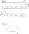
- FIGS. 6-8 show an embodiment of a microrobot train assembly and application system.
- FIG. 9 shows an embodiment of a wetting end effector.
- FIG. 1 shows a side view of a microrobot assembly system.
- the microrobot assembly system includes a substrate 10 .
- the substrate 10 may consist of a typical printed circuit board (PCB), ceramic, flex circuits, etc.
- the substrate has at least one layer of conductive traces such as 12 .
- the substrate may contain multiple layers of conductive traces such as 12 and 14 . When a controller applies voltage to these traces, the current flowing in the traces generates electromagnetic fields that can be used to control magnets.
- the magnets, such as 20 used here are single-polarity magnets, meaning that they have a single direction of magnetization, that become microrobots when joined together. As will be discussed later, the microrobots can form trains of microrobots. This discussion refers to any of these structures as magnetic structures.
- the substrate 10 has a diamagnetic layer 16 that allows the magnets to either move across the surface of the substrate with the diamagnetic layer, or even ‘float’ or levitate above the surface because of the magnetic fields.
- the magnets and microrobots can move vertically, so the plate 22 restrains the motion to prevent one of the magnets or microrobots from getting on top of the other.
- the plate 22 lies above the substrate a distance on spacers such as 18 sufficient to allow the magnets such as 20 to fit underneath the plate.
- the plate may consist of glass, aluminum, copper or any other planar material. The use of a metal plate may assist with damping eddy currents.
- the basic system includes the substrate with conductive traces, a diamagnetic layer, the plate and the magnets that eventually form the microrobots.
- the spacers such as 18 may form guides to allow the magnets to be directed into an assembly area, or incubator.
- the incubator is formed by a mechanical stop 26 , and two guides 24 and 28 .
- Guide 24 acts as an error correcting guide that allows the magnet to be driven into the guide 24 and towards the mechanical stop 26 .
- the magnets 20 and 30 have opposite directions of polarization.
- the guides may also act as the spacers.
- the guides may consist of 500 micron thick spacers for 400 micron thick magnets.
- the currents in the traces drive a magnet such as 32 into the guide rail 24 and down towards the mechanical stop 26 .
- the magnet 32 encounters magnets 30 and 20 and connects to them magnetically, forming a microrobot.
- the system drives out of the incubator area as shown by the outgoing arrow.
- One embodiment forms a microrobot of magnets of 1.4 mm by 1.4 mm by 0.4 mm magnets controllable in three or more degrees of freedom. Microrobots of greater complexity can be formed with additional magnets, end effectors, etc.
- FIGS. 3 and 4 show view of an alternative embodiment.
- This embodiment also includes the substrate 10 , the plate 22 .
- Spacers not shown in FIGS. 3 and 4 , can hold the plate 22 the desired offset from the substrate 10 .
- the conductive traces within the substrate which provide the electrically controllable magnetic forces when driven with electrical current, are divided into independently controlled zones such as 40 and 42 .
- the zone 40 constitutes a holding zone, and zone 42 a moving zone.
- suitable magnet sizes such as 1.4 ⁇ 1.4 ⁇ 0.4 mm magnets
- plate 22 can be eliminated if the geometry is stable enough to prevent flipping one magnet on top of another.
- plate 22 generally increases reliability as subtle variations in magnets or surface interactions over time during motion may cause a flip.
- Zone 40 can also move magnets and magnetic arrays using its conductive traces, but it is referred to as a holding zone because during assembly its primary function is to hold the magnets in position.
- a starting structure such as a 2 ⁇ 1 array to a position near the boundary between zone 40 and the zone 42 , but still within the holding zone 40 .
- the magnetic forces exerted by holding zone 40 may provide sufficient holding against the impact of incoming magnets.
- the guides 44 and 46 provide direction to the magnets to form the new microrobot.
- the starting structure consists of magnets 20 and 30 and magnet 48 is to be added to the structure.
- the magnet 48 is driving into the guide 44 and then along the guide 44 to magnetically attach to the starting structure.
- the magnet could also be driven along the guide 46 into the structure that now consists of magnets 48 , 30 and 20 .
- the guides 44 and 46 may both be used or only one. If the adding magnet or other added structure are well controlled, the guides may not be needed.
- the microrobot drives out of the holding zone and into the moving zone.
- FIG. 5 shows an assembly system in which multiple magnets can be assembled at once rather than individually. This also increases the controllable assembly force.
- the structure 52 has alternating pole magnets.
- the gray magnets are magnets with north poles up and the white magnets are south poles up.
- the structure 52 has two north poles adjacent to the south pole where the structure 54 is to be added. This causes an energy barrier that must be overcome to push a north pole magnet against the 2 nearby north poles before it can snap to the south pole magnet.
- the driving force may be insufficient to achieve this with a single magnet, but using two or more magnets in structure 54 may create enough force. In this manner, magnets can assemble into microrobots. In addition, microrobots can form themselves into microrobot trains.
- microrobots Similar to microrobots that need extra force to snap to other structures, some applications may need enough force to perform certain tasks. In one example, the microrobots may need more force to insert an end effector into tissue such as to perform a biopsy or other such task.
- end effector tissue such as to perform a biopsy or other such task.
- a catheter 70 would have a flex circuit, not shown, similar to the substrate and traces shown in FIG. 1 .
- the catheter has sufficient room to allow two paths, a forward path 74 and a return path 72 .
- a first microrobot 60 has a front connector 66 and a rear connector 64 .
- the microrobot 60 also has an end effector arm 62 and a tool 68 .
- the tool 68 may consist of a needle, retrieval end effector, or other type of biopsy tool.
- the microrobot 60 forms a train with other microrobots by means of the front and back connectors.
- the connectors in this embodiment consist of an eye loop 66 and a hook 64 . Connectors may also be magnetic or other means known in the prior art of small connectors.
- the microrobots can connect themselves together to form the train.
- FIG. 7 shows an example of how one microrobot can disconnect itself from the train. By moving slight backwards, as shown in FIG. 7 , the hook releases from the eye loop. As shown in FIG. 8 , the microrobot 60 then moves up to the return path 72 and the remainder of the train then moves up into the space previously occupied by microrobot 60 . This allows the system to replace one robot and one robot function with another very quickly, without withdrawing the entire instrument from the catheter each time.
- the combined microrobots can achieve a higher force than they can individually.
- the amount of force needed the number of microrobots needed in the train, based on the amount of force each microrobot can exert individually to add to the total train force.
- the region 76 of the forward and return paths 72 forms a control zone with multiple degrees of freedom. One variation would be to have multiple microrobots in the return path.
- wetting In addition to microrobot trains that can have biopsy end effectors, some end effectors use wetting to perform pick and place of items.
- One embodiment performs pick and place of small pieces of material, referred to as platelets. Issues arise with using wetting. Simple wetting surface can work, but dry out relatively quickly, and it is not easy to determine whether or not they have liquid. In addition, other surfaces are rigid and then do not wet the pick object as well as desired for reliable gripping.
- the microrobot 80 has a capillary 82 that acts as a reservoir of liquid and will typically be transparent to allow one to determine the amount of liquid in the reservoir as well as being easily fillable.
- the capillary 82 was a polyimide capillary with a diameter of 1.5 mm and length of 5-10 mm. The capillary length is normally chosen so that the liquid stays in the capillary (in liquid communication with end effector 84 ) in all robot orientations.
- the length is chosen relative to the diameter so that liquid is held in while the microrobot is in a horizontal orientation, but drops come out when the microrobot is tilted vertically, such as while operating on a flex circuit known in the prior art.
- the microrobot can therefore dispense liquid drops on demand, such as for watering plants or other automation functions where drop dispensing is desired.
- the capillary reservoir also allows the microrobot to pick and place multiple objects before needing to be refilled.
- the end effector may be porous or other absorptive material that can absorb liquids from the reservoir. These materials also provide a slight negative pressure relative to atmosphere on the liquid relative to atmosphere due to wetting of a large surface. This slight negative pressure prevents excessive water from flowing, such as on the object being picked up.
- the end effector 84 may consist of metal meshes, porous materials such as porous polyethylene, sponges, brushes, hydrogels and other high surface area wetting surfaces.
- microrobots from magnets, and microrobot trains from multiple microrobots.
- the configuration of the microrobots and the microrobot trains depends upon the desired application.
- the configuration of the microrobots may depend upon the size desired, or the number of poles desired.
- the configuration of the trains may depend upon the desired amount of force to be applied to a surface.
- the end effector used may include a porous or other absorptive material attached to a capillary that acts a reservoir of liquid.
Landscapes
- Physics & Mathematics (AREA)
- Electromagnetism (AREA)
- Engineering & Computer Science (AREA)
- Power Engineering (AREA)
- Manipulator (AREA)
Abstract
Description
Claims (11)
Priority Applications (1)
| Application Number | Priority Date | Filing Date | Title |
|---|---|---|---|
| US15/565,344 US10861627B2 (en) | 2015-04-20 | 2016-04-20 | Microrobot and microrobotic train self-assembly with end-effectors |
Applications Claiming Priority (6)
| Application Number | Priority Date | Filing Date | Title |
|---|---|---|---|
| US201562149891P | 2015-04-20 | 2015-04-20 | |
| US201562149885P | 2015-04-20 | 2015-04-20 | |
| US201562162514P | 2015-05-15 | 2015-05-15 | |
| US201662296638P | 2016-02-18 | 2016-02-18 | |
| US15/565,344 US10861627B2 (en) | 2015-04-20 | 2016-04-20 | Microrobot and microrobotic train self-assembly with end-effectors |
| PCT/US2016/028448 WO2016172217A1 (en) | 2015-04-20 | 2016-04-20 | Microrobot and microrobotic train self-assembly with end-effectors |
Publications (2)
| Publication Number | Publication Date |
|---|---|
| US20180114621A1 US20180114621A1 (en) | 2018-04-26 |
| US10861627B2 true US10861627B2 (en) | 2020-12-08 |
Family
ID=57143415
Family Applications (1)
| Application Number | Title | Priority Date | Filing Date |
|---|---|---|---|
| US15/565,344 Active 2036-12-24 US10861627B2 (en) | 2015-04-20 | 2016-04-20 | Microrobot and microrobotic train self-assembly with end-effectors |
Country Status (2)
| Country | Link |
|---|---|
| US (1) | US10861627B2 (en) |
| WO (1) | WO2016172217A1 (en) |
Cited By (1)
| Publication number | Priority date | Publication date | Assignee | Title |
|---|---|---|---|---|
| US20250332730A1 (en) * | 2024-04-29 | 2025-10-30 | L'oreal | Micro-robot gripper design for lashes |
Families Citing this family (4)
| Publication number | Priority date | Publication date | Assignee | Title |
|---|---|---|---|---|
| US11271308B2 (en) | 2017-09-05 | 2022-03-08 | Sri International | Diamagnetic mechanically based antenna |
| CN113182797B (en) * | 2021-06-02 | 2022-06-21 | 哈尔滨工业大学 | Micro-assembly system based on double macro-micro combined robots |
| CN114872013B (en) * | 2022-04-29 | 2023-12-15 | 厦门大学 | A multi-motion mode microrobot and its motion control method |
| CN116924315B (en) * | 2023-06-29 | 2026-01-23 | 清华大学 | Bionic self-replicating micro/nano robots |
Citations (40)
| Publication number | Priority date | Publication date | Assignee | Title |
|---|---|---|---|---|
| US3597022A (en) | 1969-07-22 | 1971-08-03 | Robert D Waldron | Diamagnetic levitation and/or stabilizing devices |
| US4835424A (en) | 1987-03-23 | 1989-05-30 | Megamation Incorporated | Platen laminated in mutually perpendicular direction for use with linear motors and the like |
| US5015622A (en) | 1989-10-17 | 1991-05-14 | Alfred University | Multidirectional/rotational superconductor motor |
| US5193267A (en) | 1989-05-29 | 1993-03-16 | Mitsubishi Denki Kabushiki Kaisha | Method of manufacturing magnetostriction stress detectors |
| US5298875A (en) | 1991-05-22 | 1994-03-29 | International Business Machines Corporation | Controllable levitation device |
| US5396136A (en) | 1992-10-28 | 1995-03-07 | Sri International | Magnetic field levitation |
| US5783915A (en) | 1995-01-20 | 1998-07-21 | Matsushita Electric Industrial Co., Ltd. | Linear actuating apparatus |
| US5795457A (en) | 1990-01-30 | 1998-08-18 | British Technology Group Ltd. | Manipulation of solid, semi-solid or liquid materials |
| US5925956A (en) | 1995-06-30 | 1999-07-20 | Nikon Corporation | Stage construction incorporating magnetically levitated movable stage |
| US5955800A (en) | 1995-04-06 | 1999-09-21 | University Of Sheffield | Levitation systems |
| US6064170A (en) | 1998-08-31 | 2000-05-16 | Eastman Kodak Company | Method of controlling a printhead movement based on a screw pitch to minimize swath-to-swath error in an image processing apparatus |
| US6075924A (en) | 1995-01-13 | 2000-06-13 | University Of Southern California | Intelligent motion surface |
| US6097114A (en) | 1998-08-17 | 2000-08-01 | Nikon Corporation | Compact planar motor having multiple degrees of freedom |
| US6175169B1 (en) | 1999-05-03 | 2001-01-16 | Ralph L. Hollis, Jr. | Closed-loop planar linear motor with integral monolithic three-degree-of-freedom AC-magnetic position/orientation sensor |
| WO2001068256A2 (en) | 2000-03-16 | 2001-09-20 | Sri International | Microlaboratory devices and methods |
| US6293006B1 (en) | 1998-06-15 | 2001-09-25 | Matsushita Electric Industrial Co., Ltd. | Electronic component mounting method |
| US20020020836A1 (en) | 1998-10-19 | 2002-02-21 | Nec Corporation | Thin film capacitor avoiding short circuit between electrodes |
| US6520315B1 (en) | 2000-10-26 | 2003-02-18 | Applied Materials, Inc. | Gripper assembly |
| US20030155821A1 (en) | 1999-09-02 | 2003-08-21 | U.S. Philips Corporation | Displacement device |
| US6703768B2 (en) | 2000-09-27 | 2004-03-09 | Citizen Watch Co., Ltd. | Piezoelectric generator and mounting structure therefor |
| US6922119B2 (en) | 2002-01-09 | 2005-07-26 | Alps Electric Co., Ltd. | Surface acoustic wave filter adapted to restrain undue temperature rise |
| US20050194841A1 (en) | 2004-03-03 | 2005-09-08 | Asm Assembly Automation Ltd | Decoupling of actuators for positioning an object |
| US20060078407A1 (en) | 2001-08-10 | 2006-04-13 | Asml Holding N.V. | System and method for reticle protection and transport |
| US7084533B2 (en) | 2004-04-23 | 2006-08-01 | Aerotech, Inc. | Dual-function three-axis positioning system |
| US20060175910A1 (en) | 2005-02-09 | 2006-08-10 | Canon Kabushiki Kaisha | Positioning apparatus |
| US7126134B2 (en) | 2004-08-19 | 2006-10-24 | Palo Alto Research Center Incorporated | Sample manipulator |
| US7189359B2 (en) | 2003-07-29 | 2007-03-13 | National Tsing Hua University | Electrowetting electrode device with electromagnetic field for actuation of magnetic-bead biochemical detection system |
| US7206671B2 (en) | 2002-08-21 | 2007-04-17 | Tdk Corporation | Mounting machine and controller for the mounting machine |
| US20070111117A1 (en) | 2005-11-16 | 2007-05-17 | Samsung Sdi Co., Ltd. | Laser induced thermal imaging method and fabricating method of organic light-emitting diode using the same |
| US7362586B2 (en) | 2004-05-07 | 2008-04-22 | Murata Manufacturing Co., Ltd. | Electronic component with shielding case and method of manufacturing the same |
| US20080169712A1 (en) | 2003-07-25 | 2008-07-17 | Minebea Co., Ltd. | Multi-resolver rotation angle sensor with integrated housing |
| US20090002462A1 (en) | 2007-06-29 | 2009-01-01 | Brother Kogyo Kabushiki Kaisha | Actuator unit and manufacturing method thereof, and liquid ejection head |
| US20100026443A1 (en) | 2008-07-29 | 2010-02-04 | Yipeng Yan | Magnetic Electrical Device |
| US7847824B2 (en) | 2007-03-14 | 2010-12-07 | Hoya Corporation | Shake correction apparatus of a camera |
| US8164232B2 (en) | 2004-03-12 | 2012-04-24 | Sri International | Mechanical meta-materials |
| WO2012075205A1 (en) | 2010-12-03 | 2012-06-07 | Sri International | Levitated micro-manipulator system |
| US8613500B2 (en) | 2009-11-30 | 2013-12-24 | Brother Kogyo Kabushiki Kaisha | Piezoelectric actuator, liquid discharge head, and method of manufacturing same |
| US20140123461A1 (en) | 2010-12-20 | 2014-05-08 | President And Fellows Of Harvard College | Three dimensional assembly of diamagnetic materials using magnetic levitation |
| US20140183979A1 (en) | 2010-12-03 | 2014-07-03 | Sri International | Levitated-micro manipulator system |
| US20140225694A1 (en) * | 2013-02-14 | 2014-08-14 | Carnegie Mellon University | Remotely addressable magnetic composite micro-actuators |
-
2016
- 2016-04-20 US US15/565,344 patent/US10861627B2/en active Active
- 2016-04-20 WO PCT/US2016/028448 patent/WO2016172217A1/en not_active Ceased
Patent Citations (45)
| Publication number | Priority date | Publication date | Assignee | Title |
|---|---|---|---|---|
| US3597022A (en) | 1969-07-22 | 1971-08-03 | Robert D Waldron | Diamagnetic levitation and/or stabilizing devices |
| US4835424A (en) | 1987-03-23 | 1989-05-30 | Megamation Incorporated | Platen laminated in mutually perpendicular direction for use with linear motors and the like |
| US5193267A (en) | 1989-05-29 | 1993-03-16 | Mitsubishi Denki Kabushiki Kaisha | Method of manufacturing magnetostriction stress detectors |
| US5015622A (en) | 1989-10-17 | 1991-05-14 | Alfred University | Multidirectional/rotational superconductor motor |
| US5795457A (en) | 1990-01-30 | 1998-08-18 | British Technology Group Ltd. | Manipulation of solid, semi-solid or liquid materials |
| US5298875A (en) | 1991-05-22 | 1994-03-29 | International Business Machines Corporation | Controllable levitation device |
| US5396136A (en) | 1992-10-28 | 1995-03-07 | Sri International | Magnetic field levitation |
| US6075924A (en) | 1995-01-13 | 2000-06-13 | University Of Southern California | Intelligent motion surface |
| US5783915A (en) | 1995-01-20 | 1998-07-21 | Matsushita Electric Industrial Co., Ltd. | Linear actuating apparatus |
| US5955800A (en) | 1995-04-06 | 1999-09-21 | University Of Sheffield | Levitation systems |
| US5925956A (en) | 1995-06-30 | 1999-07-20 | Nikon Corporation | Stage construction incorporating magnetically levitated movable stage |
| US6293006B1 (en) | 1998-06-15 | 2001-09-25 | Matsushita Electric Industrial Co., Ltd. | Electronic component mounting method |
| US6097114A (en) | 1998-08-17 | 2000-08-01 | Nikon Corporation | Compact planar motor having multiple degrees of freedom |
| US6064170A (en) | 1998-08-31 | 2000-05-16 | Eastman Kodak Company | Method of controlling a printhead movement based on a screw pitch to minimize swath-to-swath error in an image processing apparatus |
| US20020020836A1 (en) | 1998-10-19 | 2002-02-21 | Nec Corporation | Thin film capacitor avoiding short circuit between electrodes |
| US6175169B1 (en) | 1999-05-03 | 2001-01-16 | Ralph L. Hollis, Jr. | Closed-loop planar linear motor with integral monolithic three-degree-of-freedom AC-magnetic position/orientation sensor |
| US20030155821A1 (en) | 1999-09-02 | 2003-08-21 | U.S. Philips Corporation | Displacement device |
| US6858184B2 (en) | 2000-03-16 | 2005-02-22 | Sri International | Microlaboratory devices and methods |
| WO2001068256A3 (en) | 2000-03-16 | 2002-06-27 | Stanford Res Inst Int | Microlaboratory devices and methods |
| WO2001068256A2 (en) | 2000-03-16 | 2001-09-20 | Sri International | Microlaboratory devices and methods |
| US20020106314A1 (en) | 2000-03-16 | 2002-08-08 | Pelrine Ronald E. | Microlaboratory devices and methods |
| US6703768B2 (en) | 2000-09-27 | 2004-03-09 | Citizen Watch Co., Ltd. | Piezoelectric generator and mounting structure therefor |
| US6520315B1 (en) | 2000-10-26 | 2003-02-18 | Applied Materials, Inc. | Gripper assembly |
| US20060078407A1 (en) | 2001-08-10 | 2006-04-13 | Asml Holding N.V. | System and method for reticle protection and transport |
| US6922119B2 (en) | 2002-01-09 | 2005-07-26 | Alps Electric Co., Ltd. | Surface acoustic wave filter adapted to restrain undue temperature rise |
| US7206671B2 (en) | 2002-08-21 | 2007-04-17 | Tdk Corporation | Mounting machine and controller for the mounting machine |
| US20080169712A1 (en) | 2003-07-25 | 2008-07-17 | Minebea Co., Ltd. | Multi-resolver rotation angle sensor with integrated housing |
| US7189359B2 (en) | 2003-07-29 | 2007-03-13 | National Tsing Hua University | Electrowetting electrode device with electromagnetic field for actuation of magnetic-bead biochemical detection system |
| US20050194841A1 (en) | 2004-03-03 | 2005-09-08 | Asm Assembly Automation Ltd | Decoupling of actuators for positioning an object |
| US7084532B2 (en) | 2004-03-03 | 2006-08-01 | Asm Assembly Automation Ltd. | Decoupling of actuators for positioning an object |
| US8164232B2 (en) | 2004-03-12 | 2012-04-24 | Sri International | Mechanical meta-materials |
| US7084533B2 (en) | 2004-04-23 | 2006-08-01 | Aerotech, Inc. | Dual-function three-axis positioning system |
| US7362586B2 (en) | 2004-05-07 | 2008-04-22 | Murata Manufacturing Co., Ltd. | Electronic component with shielding case and method of manufacturing the same |
| US7126134B2 (en) | 2004-08-19 | 2006-10-24 | Palo Alto Research Center Incorporated | Sample manipulator |
| US20060175910A1 (en) | 2005-02-09 | 2006-08-10 | Canon Kabushiki Kaisha | Positioning apparatus |
| US20070111117A1 (en) | 2005-11-16 | 2007-05-17 | Samsung Sdi Co., Ltd. | Laser induced thermal imaging method and fabricating method of organic light-emitting diode using the same |
| US7847824B2 (en) | 2007-03-14 | 2010-12-07 | Hoya Corporation | Shake correction apparatus of a camera |
| US20090002462A1 (en) | 2007-06-29 | 2009-01-01 | Brother Kogyo Kabushiki Kaisha | Actuator unit and manufacturing method thereof, and liquid ejection head |
| US20100026443A1 (en) | 2008-07-29 | 2010-02-04 | Yipeng Yan | Magnetic Electrical Device |
| US8613500B2 (en) | 2009-11-30 | 2013-12-24 | Brother Kogyo Kabushiki Kaisha | Piezoelectric actuator, liquid discharge head, and method of manufacturing same |
| WO2012075205A1 (en) | 2010-12-03 | 2012-06-07 | Sri International | Levitated micro-manipulator system |
| US20140183979A1 (en) | 2010-12-03 | 2014-07-03 | Sri International | Levitated-micro manipulator system |
| US20140217835A1 (en) | 2010-12-03 | 2014-08-07 | Sri International | Levitated-micro manipulator system |
| US20140123461A1 (en) | 2010-12-20 | 2014-05-08 | President And Fellows Of Harvard College | Three dimensional assembly of diamagnetic materials using magnetic levitation |
| US20140225694A1 (en) * | 2013-02-14 | 2014-08-14 | Carnegie Mellon University | Remotely addressable magnetic composite micro-actuators |
Non-Patent Citations (3)
| Title |
|---|
| European Search Report, dated Oct. 16, 2015, EP Patent Application No. 11844154.2, 6 pages. |
| International Search Report and Written Opinion, PCT/US2016/028448, dated Sep. 13, 2016. |
| International Search Report dated Apr. 3, 2012 in corresponding International Application No. PCT/US11/62732. |
Cited By (1)
| Publication number | Priority date | Publication date | Assignee | Title |
|---|---|---|---|---|
| US20250332730A1 (en) * | 2024-04-29 | 2025-10-30 | L'oreal | Micro-robot gripper design for lashes |
Also Published As
| Publication number | Publication date |
|---|---|
| WO2016172217A1 (en) | 2016-10-27 |
| US20180114621A1 (en) | 2018-04-26 |
Similar Documents
| Publication | Publication Date | Title |
|---|---|---|
| US10861627B2 (en) | Microrobot and microrobotic train self-assembly with end-effectors | |
| CN203491037U (en) | Levitated micro-manipulator system | |
| US10286560B1 (en) | Shape compliant gripper | |
| US9647523B2 (en) | Levitated-micro manipulator system | |
| CN113589545B (en) | Shape memory alloy actuator and method | |
| US9972929B2 (en) | Magnetic contacting array | |
| CN112318488A (en) | A Magnetically Driven Bistable Flexible Actuator | |
| US20150239082A1 (en) | Parallel Kinematic Mechanism and Bearings and Actuators Thereof | |
| CN107564845B (en) | Mechanical arm | |
| US11281019B2 (en) | Lens driving device | |
| US8992183B2 (en) | System and methods for moving objects individually and in parallel | |
| US20150302964A1 (en) | Electrical component for attachment to paper and other substrates and magnetic attachment mechanism | |
| KR101406196B1 (en) | Linear desktop robot | |
| KR20220048456A (en) | Shape memory alloy actuators and methods thereof | |
| CN204094145U (en) | For the printout locating platform of three-dimensional printer | |
| Pelrine et al. | Methods and results for rotation of diamagnetic robots using translational designs | |
| Steager et al. | Control of multiple microrobots with multiscale magnetic field superposition | |
| Bogue | Microrobots and nanorobots: a review of recent developments | |
| JP6093357B2 (en) | Manufacture using a levitated manipulator robot | |
| KR102180092B1 (en) | Shape compliant module and gripper comprising the same | |
| Hu et al. | A Controllable Cargo Delivery Vehicle Driven by Electrically Actuated Galinstan Droplets | |
| CN108328569A (en) | A method of active release being carried out to small objects using fluid in microoperation | |
| JP4852699B2 (en) | Moving device and control method | |
| Elbuken et al. | Magnetic levitation as a micromanipulation technique for MEMS | |
| US20260009966A1 (en) | Lens driving device and camera module |
Legal Events
| Date | Code | Title | Description |
|---|---|---|---|
| AS | Assignment |
Owner name: SRI INTERNATIONAL, CALIFORNIA Free format text: ASSIGNMENT OF ASSIGNORS INTEREST;ASSIGNORS:PELRINE, RONALD E.;WONG-FOY, ANNJOE;HSU, ALLEN L.;AND OTHERS;SIGNING DATES FROM 20160419 TO 20160420;REEL/FRAME:043816/0298 |
|
| FEPP | Fee payment procedure |
Free format text: ENTITY STATUS SET TO UNDISCOUNTED (ORIGINAL EVENT CODE: BIG.); ENTITY STATUS OF PATENT OWNER: SMALL ENTITY |
|
| FEPP | Fee payment procedure |
Free format text: ENTITY STATUS SET TO SMALL (ORIGINAL EVENT CODE: SMAL); ENTITY STATUS OF PATENT OWNER: SMALL ENTITY |
|
| STPP | Information on status: patent application and granting procedure in general |
Free format text: DOCKETED NEW CASE - READY FOR EXAMINATION |
|
| STPP | Information on status: patent application and granting procedure in general |
Free format text: NON FINAL ACTION MAILED |
|
| STPP | Information on status: patent application and granting procedure in general |
Free format text: RESPONSE TO NON-FINAL OFFICE ACTION ENTERED AND FORWARDED TO EXAMINER |
|
| STPP | Information on status: patent application and granting procedure in general |
Free format text: RESPONSE TO NON-FINAL OFFICE ACTION ENTERED AND FORWARDED TO EXAMINER |
|
| STPP | Information on status: patent application and granting procedure in general |
Free format text: NOTICE OF ALLOWANCE MAILED -- APPLICATION RECEIVED IN OFFICE OF PUBLICATIONS |
|
| STPP | Information on status: patent application and granting procedure in general |
Free format text: PUBLICATIONS -- ISSUE FEE PAYMENT VERIFIED |
|
| STCF | Information on status: patent grant |
Free format text: PATENTED CASE |
|
| MAFP | Maintenance fee payment |
Free format text: PAYMENT OF MAINTENANCE FEE, 4TH YR, SMALL ENTITY (ORIGINAL EVENT CODE: M2551); ENTITY STATUS OF PATENT OWNER: SMALL ENTITY Year of fee payment: 4 |