US10861585B2 - Information processing apparatus and method of collecting genome data - Google Patents
Information processing apparatus and method of collecting genome data Download PDFInfo
- Publication number
- US10861585B2 US10861585B2 US15/700,802 US201715700802A US10861585B2 US 10861585 B2 US10861585 B2 US 10861585B2 US 201715700802 A US201715700802 A US 201715700802A US 10861585 B2 US10861585 B2 US 10861585B2
- Authority
- US
- United States
- Prior art keywords
- data
- addend
- count
- bits
- mutation
- Prior art date
- Legal status (The legal status is an assumption and is not a legal conclusion. Google has not performed a legal analysis and makes no representation as to the accuracy of the status listed.)
- Expired - Fee Related, expires
Links
Images


Classifications
-
- G—PHYSICS
- G16—INFORMATION AND COMMUNICATION TECHNOLOGY [ICT] SPECIALLY ADAPTED FOR SPECIFIC APPLICATION FIELDS
- G16B—BIOINFORMATICS, i.e. INFORMATION AND COMMUNICATION TECHNOLOGY [ICT] SPECIALLY ADAPTED FOR GENETIC OR PROTEIN-RELATED DATA PROCESSING IN COMPUTATIONAL MOLECULAR BIOLOGY
- G16B20/00—ICT specially adapted for functional genomics or proteomics, e.g. genotype-phenotype associations
- G16B20/20—Allele or variant detection, e.g. single nucleotide polymorphism [SNP] detection
-
- G—PHYSICS
- G16—INFORMATION AND COMMUNICATION TECHNOLOGY [ICT] SPECIALLY ADAPTED FOR SPECIFIC APPLICATION FIELDS
- G16B—BIOINFORMATICS, i.e. INFORMATION AND COMMUNICATION TECHNOLOGY [ICT] SPECIALLY ADAPTED FOR GENETIC OR PROTEIN-RELATED DATA PROCESSING IN COMPUTATIONAL MOLECULAR BIOLOGY
- G16B30/00—ICT specially adapted for sequence analysis involving nucleotides or amino acids
Definitions
- the disclosures herein relate to an information processing apparatus, a program for collecting genome data, and a method of collecting genome data.
- the DNA sequence of a single human includes tens of millions of positions at which gene mutation patterns may occur. Collecting the numbers of occurrences of gene mutation patterns is thus time consuming.
- Patent Document 1 Japanese National Publication of International Patent Application No. 2002-509316
- an information processing apparatus includes a memory and a processor coupled to the memory and configured to extract data having x times y bits from genome data in which a mutation pattern at each gene mutation position is represented as x bits, such that the extracted data is constituted by y data pieces each having x bits at y respective mutation positions, x and y being integers greater than or equal to 1, respectively, to refer to an addend table that stores a plurality of addend data associated with respective x-times-y-bit data to identify addend data corresponding to the extracted data, and to use an SIMD instruction to add the identified addend data to count data at positions corresponding to the y mutation positions in the genome data, the count data indicating counts of occurrences of mutation patterns in the genome data.
- FIG. 1 is a drawing illustrating an example of the entire configuration of a data collecting apparatus according to an embodiment
- FIG. 2 is a drawing illustrating the outline of the data collection process according to the embodiment
- FIG. 3 is a drawing illustrating an example of the hardware configuration of the data collecting apparatus according to the embodiment.
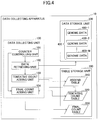
- FIG. 4 is a drawing illustrating an example of the functional configuration of a data collecting unit of the data collecting apparatus according to the embodiment
- FIG. 5 is a drawing illustrating an example of an addend table
- FIG. 6 is a drawing illustrating an example of a tentative count table
- FIG. 7 is a drawing illustrating an example of a final count table
- FIG. 8 is a flowchart illustrating an example of a data collection process according to the embodiment.
- FIG. 9 is a flowchart illustrating an example of the process of updating a final count table according to the embodiment.
- FIG. 10 is a drawing illustrating an example of identifying possible disease-related positions by use of the data collection process according to the embodiment.
- FIG. 1 is a drawing illustrating an example of the entire configuration of the data collecting apparatus 10 according to the present embodiment.
- the data collecting apparatus 10 illustrated in FIG. 1 which is an information processing apparatus such as a personal computer, includes a data collecting unit 100 , a data storage unit 200 , and a table storage unit 300 .
- the data storage unit 200 stores genome data 400 for a plurality of people. Namely, the data storage unit 200 stores genome data 400 - 1 for a first person, genome data 400 - 2 for a second person, . . . , and genome data 400 -M for an M-th person.
- genome data 400 is used when the genome data 400 - 1 , the genome data 400 - 2 , . . . , and the genome data 400 -M are not discriminated from each other.
- the genome data 400 used in the present embodiment represents mutation patterns as a bit sequence having two bits with respect to each position at which an SNP (single nucleotide polymorphism) occurs in the DNA sequence of humans or the like.
- the SNP patterns at a specific position (which is herein referred to as “POSITION0”) in the DNA sequence of humans or the like may be “A/A”, “A/C”, and “C/C”.
- the mutation patterns at the “POSITION0” in the genome data 400 may be represented as “00”, “01”, and “10”, which are a bit sequence constituted by two bits.
- the SNP patterns at another specific position (which is herein referred to as “POSITION1”) in the DNA sequence of humans or the like may be “C/C”, “C/G”, and “G/G” as illustrated in FIG. 1 .
- the mutation patterns at the “POSITION1” in the genome data 400 may be represented as “00”, “01”, and “10”, which are a bit sequence constituted by two bits.
- the genome data 400 represents mutation patterns as a bit sequence having two bits at each of the N positions at which SNPs occur in the DNA sequence of humans or the like.
- the genome data 400 is a series of arranged bit sequences each having two bits for representing mutation patterns at the position of an SNP.
- the genome data 400 is not limited to such a configuration.
- the genome data 400 may alternatively represent the number of copies of CNVs (i.e., copy number variations) as a bit sequence having a predetermined number of bits with respect to each range within which CNVs occur, for example.
- the genome data 400 may alternatively represent the number of repeats such as VNTRs (i.e., variable number of tandem repeats) or STRPs (i.e., short tandem repeat polymorphisms) as a bit sequence having a predetermined number of bits with respect to each range within which such repeats occur.
- VNTRs i.e., variable number of tandem repeats
- STRPs i.e., short tandem repeat polymorphisms
- the data collecting unit 100 performs a data collection process for the genome data 400 stored in the data storage unit 200 . Namely, the data collecting unit 100 counts the number of occurrences of mutation patterns at each position with respect to the genome data 400 stored in the data storage unit 200 .
- the table storage unit 300 stores various types of tables for use by the data collecting unit 100 in collecting the genome data 400 .
- the table storage unit 300 stores an addend table 310 , a tentative count table 320 , and a final count table 330 .
- the addend table 310 is a look-up table in which addend data to be added to the counts of occurrences of mutation patterns are stored.
- the tentative count table 320 stores tentative count data indicative of tentative counts with respect to the numbers of occurrences of mutation patterns.
- the final count table 330 stores final count data indicative of final counts with respect to the numbers of occurrences of mutation patterns.
- FIG. 2 is a drawing illustrating the outline of the data collection process according to the present embodiment.
- the data collecting unit 100 extracts a bet sequence having 8 bits from POSITION0 to POSITION3 of the genome data 400 - 1 . Namely, the data collecting unit 100 extracts the bit sequence “00011010” from POSITION0 through POSITION3.
- the data collecting unit 100 refers to the addend table 310 to identify the addend data corresponding to the same index as the extracted bit sequence, and uses an SIMD (single instruction multiple data) instruction to add the identified data to the tentative count data in the tentative count table 320 .
- SIMD single instruction multiple data
- the data collecting unit 100 uses an SIMD instruction to add the addend data “1000010001000010” corresponding to the index “00011010” in the addend table 310 to the tentative count data at POSITION0 through POSITION3 in the tentative count table 320 .
- the data size of each digit of “1000010001000010” is 16 bits.
- the data size of the addend data is thus equal to 16 bits times 16 , which is 256 bits.
- “1” is added to the tentative count data corresponding to the bit sequence “00” at POSITION0 in the tentative count table 320 .
- the data collecting unit 100 further performs the processes of steps S 1 - 1 and S 1 - 2 noted above with respect to POSITION4 through POSITION7, POSITION8 through POSITION11, . . . , and POSITION(N ⁇ 4) through POSITION(N ⁇ 1) (i.e., the N ⁇ 4-th position through the N ⁇ 1-th position) of the genome data 400 - 1 .
- the data collecting unit 100 performs the processes of steps S 1 - 1 and S 1 - 2 noted above with respect to POSITION0 through POSITION3, . . . , and POSITION(N ⁇ 4) through POSITION(N ⁇ 1) of each of the genome data 400 - 2 through the genome data 400 -M.
- the number “N” of positions included in the genome data 400 is an integer multiple of 4. In the case of the number of positions in the genome data being not an integer multiple of 4, as many positions having the bit sequence “00” as appropriate may be added to the genome data 400 , thereby making the number of positions in the genome data 400 equal to an integer multiple of 4.
- the data collecting unit 100 updates the final count table 330 based on the tentative count table 320 after a predetermined number of genome data 400 are tallied in the tentative count table 320 . Namely, the data collecting unit 100 adds the tentative count data in the tentative count table 320 to the final count data in the final count table 330 .
- the data collecting apparatus 10 of the present embodiment counts the numbers of occurrences of mutation patterns at each position with respect to a plurality of genome data 400 .
- the data collecting apparatus 10 of the present embodiment refers to the addend table 310 to identify the addend data corresponding to the index, and, then, utilizes an SIMD instruction to add the identified addend data to the tentative count data in the tentative count table 320 .
- the data collecting apparatus 10 of the present embodiment utilizes a single instruction (i.e., SIMD instruction) with respect to every four positions to count the numbers of occurrences of mutation patterns at these four positions as described above.
- the data collecting apparatus 10 of the present embodiment is thus able to perform addition with respect to tentative count data without performing either a shift operation or a masking operation, thereby enabling high-speed counting of occurrences of mutation patterns.
- the data collecting apparatus 10 of the present embodiment will be described as extracting one bit sequence from every four positions in the genome data 400 , such that the mutation pattern at each of these positions is represented by two corresponding bits in the bits sequence. This is, however, not a limiting example.
- the data collecting apparatus 10 of the present embodiment may extract one bit sequence from every y positions in the genome data 400 , such that the mutation pattern at each of these positions is represented by x corresponding bits in the bit sequence where x is an integer greater than or equal to 1, and y is an integer greater than or equal to 1.
- the data collecting apparatus 10 of the present embodiment is able to perform addition simultaneously at a plurality of positions with respect to the numbers of occurrences of mutation patterns. This arrangement thus enables faster counting of occurrences of mutation patterns. Because of this, y is preferably an integer that is two or greater.
- FIG. 3 is a drawing illustrating an example of the hardware configuration of the data collecting apparatus 10 according to the present embodiment.
- the data collecting apparatus 10 of the present embodiment includes an input device 11 , a display device 12 , an external I/F 13 , and a communication I/F 14 .
- the data collecting apparatus 10 of the present embodiment further includes a ROM (read only memory) 15 , a RAM (random access memory) 16 , a CPU (central processing unit) 17 , and an HDD (hard disk drive) 18 . These hardware units are coupled to each other through a bus B.
- the input device 11 includes a keyboard, a mouse, a touch panel, and the like for use by a user in performing various operations.
- the display device 12 displays process results obtained by the data collecting apparatus 10 . At least one of the input device 11 and the display device 12 may be configured to be coupled to the bus B only when such a need arises.
- the communication I/F 14 is an interface for connecting the data collecting apparatus 10 to a network.
- the data collecting apparatus 10 performs data communication through the communication I/F 14 .
- the HDD 18 is a nonvolatile storage device that stores programs and data.
- the HDD 18 stores an OS (operating system) that is basic software for controlling the entirety of the data collecting apparatus 10 , and also stores application software for providing various functions on the OS.
- the HDD 18 stores programs for implementing the data collecting unit 100 and the genome data 400 .
- the HDD 18 uses a file system or database to manage the programs and data stored therein.
- the data collecting apparatus 10 may include a drive device utilizing flash memories as a memory medium (e.g., solid-state drive SSD).
- a drive device utilizing flash memories as a memory medium e.g., solid-state drive SSD.
- the external I/F 13 is an interface for external apparatus.
- the external apparatus may include a recording medium 13 a .
- the data collecting apparatus 10 performs read and write operations with respect to the recording medium 13 a through the external I/F 13 .
- the recording medium 13 a may be a CD, a DVD, an SD-memory card, a USB memory stick, or the like.
- the ROM 15 is a nonvolatile semiconductor memory (storage device) that can retain programs and data even when the power is switched off.
- the ROM 15 stores programs and data for OS settings, network settings, and the like as well as BIOS (basic input/output system) and the like that are executed at the time of activation of the data collecting apparatus 10 .
- the RAM 16 is a volatile semiconductor memory that temporarily stores programs and data.
- the CPU 17 loads programs and data into the RAM 16 from the memory devices such as the ROM 15 and the HDD 18 , and performs processes based on these programs and data, thereby implementing the overall control and other functions of the data collecting apparatus 10 .
- the CPU 17 of the data collecting apparatus 10 of the present embodiment is capable of processing 256-bit data in response to a SIMD instruction.
- the data collecting apparatus 10 of the present embodiment has the hardware configuration illustrated in FIG. 3 to implement various processes as will be described later.
- FIG. 4 is a drawing illustrating an example of the functional configuration of the data collecting unit 100 of the data collecting apparatus 10 according to the present embodiment.
- the data collecting unit 100 of the present embodiment includes a counter controlling unit 101 , a data retrieving unit 102 , a tentative count adding unit 103 , and a final count adding unit 104 .
- the data collecting unit 100 is implemented as one or more processes that are performed by the CPU 17 under the control of one or more programs installed in the data collecting apparatus 10 .
- the counter controlling unit 101 controls various types of counters used in the data collection process. For example, the counter controlling unit 101 controls a counter m for indicating an m-th genome data 400 - m stored in the data storage unit 200 . Further, the counter controlling unit 101 controls a counter n for identifying POSITION(N) in the genome data 400 .
- the counter controlling unit 101 checks which one of the count of a given counter and a predetermined threshold is greater than the other. For example, the counter controlling unit 101 checks whether the count of the counter m is smaller than M+1. Further, the counter controlling unit 101 checks whether the count of the counter n is smaller than N.
- the data retrieving unit 102 retrieves the genome data 400 - m indicated by the counter m among the genome data 400 stored in the data storage unit 200 .
- the tentative count adding unit 103 extracts a bit sequence of POSITION(n) through POSITION(n+3) indicated by the counter n from the genome data 400 - m retrieved by the data retrieving unit 102 .
- the tentative count adding unit 103 refers to the addend table 310 to identify the addend data having the same index as the extracted bit sequence, and uses an SIMD instruction to add the identified addend data to the tentative count data of POSITION(n) through POSITION(n+3) in the tentative count table 320 .
- FIG. 5 is a drawing illustrating an example of the addend table 310 .
- the addend table 310 of the present embodiment stores addend data associated with respective indexes each being an 8-bit sequence, for use in adding up the numbers of occurrences of mutation patterns.
- the addend table 310 of the present embodiment has the indexes ranging from “00000000” to “11111111”, which indicate that there are 256 entries of addend data.
- Each of the addend data stored in the addend table 310 of the present embodiment includes 16 addends, each of which has 16 bits.
- the addend table 310 of the present embodiment may thus be implemented as sum table[256] which is an array of elements each having 256 bits.
- the array indexes “0” through “255” for indicating the respective elements are expressed in 8 bits as the indexes of the addend table 310 .
- Each addend contained in given addend data has a value assigned thereto in correspondence with the index of the given addend data.
- the index may be expressed as “A 00 A 01 A 10 A 11 A 20 A 21 A 30 A 31 ”.
- the addend may be expressed as “X 00 X 01 X 02 X 03 X 10 X 11 X 12 X 13 X 20 X 21 X 22 X 23 X 30 X 31 X 32 X 33 ”.
- an SIMD instruction is able to perform addition with respect to the tentative count data stored in the tentative count table 320 .
- FIG. 6 is a drawing illustrating an example of the tentative count table 320 .
- the tentative count table 320 of the present embodiment stores tentative count data indicative of the tentative counts of occurrences of mutation patterns such that the tentative count data are associated with positions in the genome data 400 and with bit sequences representing mutation patterns.
- each tentative count data is represented as 16 bits.
- the tentative count table 320 of the present embodiment may thus be implemented as tmp_table[N/4] which is an array of elements each having 256 bits.
- the array element “tmp_table[0]” stores the tentative count data of POSITION0 through POSITION3.
- the array element “tmp_table[1]” stores the tentative count data of POSITION4 through POSITION7.
- the array element “tmp_table[(N/4) ⁇ 1]” stores the tentative count data of POSITION(N ⁇ 4) through POSITION(N ⁇ 1).
- each addend data in the addend table 310 includes 16 addends each of which is represented as 16 bits. Further, each of the 16 tentative count data at POSITION(n) through POSITION(n+3) in the tentative count table 320 is represented as 16 bits. With this arrangement, the tentative count adding unit 103 is able to use an SIMD instruction to add the addend data in the addend table 310 to the tentative count data at POSITION(n) through POSITION(n+3) in the tentative count table 320 .
- the final count adding unit 104 updates the final count table 330 based on the tentative count table 320 when the count of the counter m exceeds a predetermined value. Namely, the final count adding unit 104 adds the tentative count data in the tentative count table 320 to the final count data in the final count table 330 .
- the data size of the tentative count data in the tentative count table 320 of the present embodiment is 16 bits. With this arrangement, the tentative count data in the tentative count table 320 suffices to count the occurrences of mutation patterns within a range of 0 to 65535 (i.e., the range that can be expressed by use of 16 bits).
- the data collecting apparatus 10 of the present embodiment thus adds the tentative count data in the tentative count table 320 to the final count data in the final count table 330 when the count of the counter m becomes greater than or equal to 65536.
- a value of 65535 is an example of the largest value that can be expressed by the data size of the count data.
- FIG. 7 is a drawing illustrating an example of the final count table 330 .
- the final count table 330 of the present embodiment stores final count data indicative of the final counts of occurrences of mutation patterns such that the final count data are associated with positions in the genome data 400 and with bit sequences representing mutation patterns.
- each final count data is represented by a larger data size (e.g., 24 bits, 32 bits, or the like) than 16 bits. Namely, the data size of final count data is larger than the data size of tentative count data (which is 16 bits).
- the final count table 330 of the present embodiment may thus be implemented as result_table[N][3] which is a two-dimensional array of elements each having a larger data size than 16 bits.
- the array elements “result_table[0][0]” through “result_table[0][2]” store the final count data for the bit sequences “00” through “10” at POSITION0.
- the array elements “result_table[1][0]” through “result_table[1][2]” store the final count data for the bit sequences “00” through “10” at POSITION1.
- the array elements “result_table[N ⁇ 1][0]” through “result_table[N ⁇ 1][2]” store the final count data for the bit sequences “00” through “10” at POSITION(N ⁇ 1).
- the final count table 330 stores final count data indicative of the numbers of occurrences of mutation patterns at each position in the genome data 400 .
- the final count table 330 has no final count data for the bit sequence “11”. This is because the SNP patterns are fully represented as the bit sequences “00”, “01”, and “10”. Alternatively, the SNP patterns may be represented as “A/A”, “A/C”, “C/A”, and “C/C” by discriminating between the paternal line and the maternal line. In such a case, the SNP patterns are represented as the bits sequences “00”, “01”, “10”, and “11”. When this is the case, the final count table 330 may store final count data for the bit sequence “11”.
- FIG. 8 is a flowchart illustrating an example of the data collection process according to the present embodiment.
- the counter controlling unit 101 sets an initial value of “1” to the counter m that indicates an m-th genome data 400 - m stored in the data storage unit 200 .
- the counter controlling unit 101 sets an initial value of “0” to the counter n that indicates POSITION(n) in the genome data 400 .
- the data retrieving unit 102 retrieves the genome data 400 - m among the genome data 400 stored in the data storage unit 200 , and stores the retrieved data in p[N/4] which is an array of elements each having 8 bits.
- the data retrieving unit 102 retrieves the genome data 400 - m from the data storage unit 200 , and stores in the array element “p[0]” the bit sequence of POSITION0 through POSITION3 in the retrieved genome data 400 - m .
- the data retrieving unit 102 further stores in the array element “p[1]” the bit sequence of POSITION4 through POSITION7 in the genome data 400 - m .
- the data retrieving unit 102 further stores in the array element “p[(N/4) ⁇ 1]” the bit sequence of POSITION(N ⁇ 4) through POSITION(N ⁇ 1) in the genome data 400 - m.
- the tentative count adding unit 103 extracts the bit sequence stored in the array element “p[n/4]”.
- the tentative count adding unit 103 refers to the addend table 310 to identify the addend data having the same index as the extracted bit sequence, and uses an SIMD instruction to add the identified addend data to the tentative count data of POSITION(n) through POSITION(n+3) in the tentative count table 320 .
- the tentative count adding unit 103 adds the addend data stored in the array element “sum table[p[n/4]] to the array element “tmp_table[n/4]” by use of an SIMD instruction.
- the tentative count adding unit 103 adds the addend data at the same index as the bit sequence of POSITION(n) through POSITION(n+3) in the genome data 400 - m to the tentative count data at POSITION(n) through POSITION(n+3) in the tentative count table 320 . It should be further noted that the tentative count adding unit 103 is able to add the addend data corresponding to the bit sequence for 4 positions in the genome data 400 - m to the tentative count data for 4 positions.
- step S 805 the counter controlling unit 101 adds “4” to the counter n. Namely, the counter controlling unit 101 sets n equal to n+4.
- step S 806 the counter controlling unit 101 checks whether the count of the counter n is smaller than N.
- step S 806 When the counter controlling unit 101 determines at step S 806 that the count of the counter n is smaller than N, the data collecting unit 100 returns to step S 804 to perform the process thereof. Namely, the tentative count adding unit 103 performs the process of step S 804 with respect to each value of n, i.e., 0, 4, 8, . . . , and N ⁇ 4.
- step S 806 When it is determined at step S 806 that the count of the counter n is not smaller than N, the counter controlling unit 101 adds “1” to the counter m (step S 807 ). Namely, the counter controlling unit 101 sets m equal to m+1.
- the counter controlling unit 101 checks whether the count of the counter m is smaller than 65536.
- step S 808 This check at step S 808 as to whether the count of the counter m is smaller than 65536 is made in order to ensure that no data loss occurs in the tentative count data.
- the counter controlling unit 101 may alternatively check whether at least one of the tentative count data in the tentative count table 320 has reached 65535 .
- the data collecting unit 100 uses the final count adding unit 104 at step S 809 to update the final count table 330 based on the tentative count table 320 .
- the detail of the process at this step for updating the final count table will be described later.
- step S 808 determines at step S 808 that the count of the counter m is smaller than 65536, or immediately after step S 809 , the counter controlling unit 101 checks at step S 810 whether the count of the counter m is smaller than M+1.
- step S 810 When the counter controlling unit 101 determines at step S 810 that the count of the counter m is smaller than M+1, the data collecting unit 100 returns to step S 802 to perform the process thereof. Namely, the data collecting unit 100 performs the processes of steps S 802 through S 809 with respect to each value of m, i.e., 1, 2, . . . , and M.
- the data collecting unit 100 brings the data collection process to an end. In this manner, the data collecting unit 100 counts the numbers of occurrences of mutation patterns at each position in the genome data 400 .
- FIG. 9 is a flowchart illustrating an example of the process of updating a final count table according to the present embodiment.
- the counter controlling unit 101 sets an initial value of “0” to the counter n that indicates POSITION(n) in the genome data 400 .
- the final count adding unit 104 stores, in tmp_agg[4] which is an array of elements each having 64 bits, the tentative count data of POSITION(n) through POSITION(n+3) in the tentative count table 320 .
- the final count adding unit 104 stores in the array element “tmp_agg[0]” the tentative count data of POSITION(n) in the tentative count table 320 .
- the final count adding unit 104 further stores in the array element “tmp_agg[1]” the tentative count data of POSITION(n+1) in the tentative count table 320 .
- the final count adding unit 104 further stores in the array elements “tmp_agg[2]” and “tmp_agg[3]” the tentative count data of POSITION(n+2) and POSITION(n+3) in the tentative count table 320 , respectively.
- the counter controlling unit 101 sets an initial value of “0” to a counter k indicating a bit sequence.
- the counter k which has 2 bits, indicates a bit sequence representing a mutation pattern.
- the bit sequence indicated by the counter k is denoted as the bit sequence k.
- the final count adding unit 104 adds the tentative count data of the bit sequence k at POSITION(n) in the tentative count table 320 to the final count data of the bit sequence k at POSITION(n) in the final count table 330 .
- the final count adding unit 104 performs a 16 k-bit right shift with respect to the array element “tmp_agg[0]”, and masks the resultant data with “0x00000000000000ff”, followed by adding the masked data to the array element “result_table[n][k]”.
- the final count adding unit 104 adds the tentative count data of the bit sequence k at POSITION(n+1) in the tentative count table 320 to the final count data of the bit sequence k at POSITION(n+1) in the final count table 330 .
- the final count adding unit 104 performs a 16 k-bit right shift with respect to the array element “tmp_agg[1]”, and masks the resultant data with “0x00000000000000ff”, followed by adding the masked data to the array element “result_table[n+1][k]”.
- the final count adding unit 104 adds the tentative count data of the bit sequence k at POSITION(n+2) in the tentative count table 320 to the final count data of the bit sequence k at POSITION(n+2) in the final count table 330 .
- the final count adding unit 104 performs a 16 k-bit right shift with respect to the array element “tmp_agg[2]”, and masks the resultant data with “0x00000000000000ff”, followed by adding the masked data to the array element “result_table[n+2][k]”.
- the final count adding unit 104 adds the tentative count data of the bit sequence k at POSITION(n+3) in the tentative count table 320 to the final count data of the bit sequence k at POSITION(n+3) in the final count table 330 .
- the final count adding unit 104 performs a 16 k-bit right shift with respect to the array element “tmp_agg[3]”, and masks the resultant data with “0x00000000000000ff”, followed by adding the masked data to the array element “result_table[n+3][k]”.
- step S 908 the counter controlling unit 101 adds “1” to the counter k. Namely, the counter controlling unit 101 sets k equal to k+1.
- step S 909 the counter controlling unit 101 checks whether the count of the counter k is smaller than 3.
- the SNP patterns may be represented as “A/A”, “A/C”, “C/A”, and “C/C”, for example, by discriminating between the paternal line and the maternal line.
- addition is performed with respect to the final count data of the bit sequence k at POSITION(n+4) before step S 908 is performed.
- the counter controlling unit 101 checks at above-noted step S 909 whether the count of the counter k is smaller than 4.
- step S 909 When the counter controlling unit 101 determines at step S 909 that the count of the counter k is smaller than 3, the data collecting unit 100 returns to step S 904 to perform the process thereof. Namely, the data collecting unit 100 performs the processes of steps S 904 through S 909 with respect to each value of k, i.e., 0, 1, and 2.
- the counter controlling unit 101 determines that the count of the counter k is not smaller than 3, the counter controlling unit 101 adds “4” to the counter n at step S 910 . Namely, the counter controlling unit 101 sets n equal to n+4.
- step S 911 the counter controlling unit 101 checks whether the count of the counter n is smaller than N.
- step S 911 When the counter controlling unit 101 determines at step S 911 that the count of the counter n is smaller than N, the data collecting unit 100 returns to step S 902 to perform the process thereof. Namely, the data collecting unit 100 performs the processes of steps S 902 through S 910 with respect to each value of n, i.e., 0, 4, 8, . . . , and N ⁇ 4.
- the final count adding unit 104 initializes the tentative count data to “0” in the tentative count table 320 at step S 912 . Namely, the final count adding unit 104 sets an initial value of “0” to the array elements “tmp_table[0]” through “tmp_table[(N/4) ⁇ 1]”.
- the data collecting apparatus 10 of the present embodiment counts the numbers of occurrences of mutation patterns at each position with respect to a plurality of genome data 400 . In so doing, the data collecting apparatus 10 of the present embodiment identifies addend data by use of an 8-bit sequence corresponding to 4 positions in the genome data 400 , and utilizes an SIMD instruction to add the identified addend data to the tentative count table 320 .
- the data collecting apparatus 10 of the present embodiment does not need to use either a shift operation or a masking operation when counting in the tentative count table 320 the numbers of occurrences of mutation patterns at each position in the genome data 400 .
- the data collecting apparatus 10 of the present embodiment thus enables high-speed counting of occurrences of mutation patterns at each position in the genome data 400 .
- the data collecting apparatus 10 of the present embodiment has been described as having the CPU 17 that is capable of processing 256-bit data in response to an SIMD instruction. This is not a limiting example, and the CPU 17 may alternatively be capable of processing 512-bit data in response to an SIMD instruction. In such a case, the data collecting apparatus 10 of the present embodiment may identify 512-bit addend data by use of a 16-bit sequence corresponding to 8 positions in the genome data 400 , and may utilize an SIMD instruction to add the identified addend data to the tentative count table 320 .
- the data collecting apparatus 10 of the present embodiment may use an appropriate number of bits for a bit sequence extracted from the genome data 400 and for indexes and addend data in the addend table 310 as such an appropriate number is determined in response to the number of bits of an SIMD instruction processable by the CPU 17 .
- FIG. 10 is a drawing illustrating an example of identifying possible disease-related positions by use of the data collection process according to the present embodiment.
- the genome data 400 stored in the data storage unit 200 includes genome data 410 belonging to people of normal health free from a disease of interest and genome data 420 belonging to people having such a disease.
- the data collecting apparatus 10 of the present embodiment counts the numbers of occurrences of mutation patterns at each position in the genome data 410 to generate a final count table 330 - 1 belonging to the people having no such disease. Similarly, the data collecting apparatus 10 of the present embodiment counts the numbers of occurrences of mutation patterns at each position in the genome data 420 to generate a final count table 330 - 2 belonging to the people having the disease.
- Position-specific distributions of counted occurrences of mutation patterns are created based on the final count table 330 - 1 . Also, position-specific distributions of counted occurrences of mutation patterns (for the people having the disease) are created based on the final count table 330 - 2 .
- possible disease-related positions may be identified by determining whether there are significant differences between the distributions of people having no such disease and the distributions of people having the disease.
- the data collecting apparatus 10 of the present embodiment may be used in the data collection process for identifying possible disease-related positions among the positions at which SNP patterns occur in the DNA sequence.
- the data collecting apparatus 10 of the present embodiment may equally be applicable to a data collection process for counting the numbers of occurrences of patterns when such patterns in data are represented as a bit sequence having a predetermined number of bits.
- the time needed to collect genome data is shortened.
Landscapes
- Life Sciences & Earth Sciences (AREA)
- Physics & Mathematics (AREA)
- Health & Medical Sciences (AREA)
- Bioinformatics & Cheminformatics (AREA)
- Engineering & Computer Science (AREA)
- Biotechnology (AREA)
- General Health & Medical Sciences (AREA)
- Biophysics (AREA)
- Analytical Chemistry (AREA)
- Bioinformatics & Computational Biology (AREA)
- Chemical & Material Sciences (AREA)
- Evolutionary Biology (AREA)
- Proteomics, Peptides & Aminoacids (AREA)
- Medical Informatics (AREA)
- Spectroscopy & Molecular Physics (AREA)
- Theoretical Computer Science (AREA)
- Genetics & Genomics (AREA)
- Molecular Biology (AREA)
- Medical Treatment And Welfare Office Work (AREA)
- Apparatus Associated With Microorganisms And Enzymes (AREA)
- Management, Administration, Business Operations System, And Electronic Commerce (AREA)
Abstract
Description
Claims (5)
Applications Claiming Priority (2)
| Application Number | Priority Date | Filing Date | Title |
|---|---|---|---|
| JP2016-181677 | 2016-09-16 | ||
| JP2016181677A JP6756209B2 (en) | 2016-09-16 | 2016-09-16 | Information processing device, genome data aggregation program, and genome data aggregation method |
Publications (2)
| Publication Number | Publication Date |
|---|---|
| US20180082013A1 US20180082013A1 (en) | 2018-03-22 |
| US10861585B2 true US10861585B2 (en) | 2020-12-08 |
Family
ID=61621170
Family Applications (1)
| Application Number | Title | Priority Date | Filing Date |
|---|---|---|---|
| US15/700,802 Expired - Fee Related US10861585B2 (en) | 2016-09-16 | 2017-09-11 | Information processing apparatus and method of collecting genome data |
Country Status (2)
| Country | Link |
|---|---|
| US (1) | US10861585B2 (en) |
| JP (1) | JP6756209B2 (en) |
Citations (5)
| Publication number | Priority date | Publication date | Assignee | Title |
|---|---|---|---|---|
| US20010028741A1 (en) | 1997-12-30 | 2001-10-11 | Christer Fahraeus | Method and a device for matching images |
| JP2002509316A (en) | 1997-12-30 | 2002-03-26 | シー テクノロジーズ アクチボラゲット | Image matching method and apparatus |
| US20080086274A1 (en) * | 2006-08-10 | 2008-04-10 | Chamberlain Roger D | Method and Apparatus for Protein Sequence Alignment Using FPGA Devices |
| US7917302B2 (en) * | 2000-09-28 | 2011-03-29 | Torbjorn Rognes | Determination of optimal local sequence alignment similarity score |
| US9165253B2 (en) * | 2012-08-31 | 2015-10-20 | Real Time Genomics Limited | Method of evaluating genomic sequences |
-
2016
- 2016-09-16 JP JP2016181677A patent/JP6756209B2/en not_active Expired - Fee Related
-
2017
- 2017-09-11 US US15/700,802 patent/US10861585B2/en not_active Expired - Fee Related
Patent Citations (5)
| Publication number | Priority date | Publication date | Assignee | Title |
|---|---|---|---|---|
| US20010028741A1 (en) | 1997-12-30 | 2001-10-11 | Christer Fahraeus | Method and a device for matching images |
| JP2002509316A (en) | 1997-12-30 | 2002-03-26 | シー テクノロジーズ アクチボラゲット | Image matching method and apparatus |
| US7917302B2 (en) * | 2000-09-28 | 2011-03-29 | Torbjorn Rognes | Determination of optimal local sequence alignment similarity score |
| US20080086274A1 (en) * | 2006-08-10 | 2008-04-10 | Chamberlain Roger D | Method and Apparatus for Protein Sequence Alignment Using FPGA Devices |
| US9165253B2 (en) * | 2012-08-31 | 2015-10-20 | Real Time Genomics Limited | Method of evaluating genomic sequences |
Non-Patent Citations (2)
| Title |
|---|
| World Intellectual Property Organization English abstract for International Publication No. WO 99/36879 published Jul. 22, 1999 corresponding to Japanese Publication No. 2002-509316. |
| Zhou, Jingren, and Kenneth A. Ross. "Implementing database operations using SIMD instructions." Proceedings of the 2002 ACM SIGMOD international conference on Management of data. 2002. * |
Also Published As
| Publication number | Publication date |
|---|---|
| JP6756209B2 (en) | 2020-09-16 |
| US20180082013A1 (en) | 2018-03-22 |
| JP2018045586A (en) | 2018-03-22 |
Similar Documents
| Publication | Publication Date | Title |
|---|---|---|
| US10204208B2 (en) | Systems and methods for genomic variant annotation | |
| Rau et al. | Co-expression analysis of high-throughput transcriptome sequencing data with Poisson mixture models | |
| US8751166B2 (en) | Parallelization of surprisal data reduction and genome construction from genetic data for transmission, storage, and analysis | |
| EP3136284B1 (en) | Personal information anonymization method, personal information anonymization program, and information processing apparatus | |
| US20210104298A1 (en) | Secure communication of nucleic acid sequence information through a network | |
| CN108717461B (en) | Mass data structuring method and device, computer equipment and storage medium | |
| Denti et al. | MALVA: genotyping by Mapping-free ALlele detection of known VAriants | |
| CN113761185B (en) | Primary key extraction method, device and storage medium | |
| US20160048633A1 (en) | Systems and methods for genomic variant annotation | |
| CN112885412A (en) | Genome annotation method, apparatus, visualization platform and storage medium | |
| CN113688629A (en) | Method, device and storage medium for text deduplication | |
| Meher et al. | A statistical approach for 5′ splice site prediction using short sequence motifs and without encoding sequence data | |
| WO2013140313A1 (en) | Surprisal data reduction of genetic data for transmission, storage, and analysis | |
| CN110532425B (en) | Video data distributed storage method and device, computer equipment and storage medium | |
| WO2019084236A1 (en) | Method and system for generating and comparing genotypes | |
| Kouchaki et al. | A signal processing method for alignment-free metagenomic binning: multi-resolution genomic binary patterns | |
| US10861585B2 (en) | Information processing apparatus and method of collecting genome data | |
| Chen et al. | Novel and efficient tag SNPs selection algorithms | |
| Orozco-Arias et al. | Automatic curation of LTR retrotransposon libraries from plant genomes through machine learning | |
| US20140200920A1 (en) | Method and apparatus for associating patient identifiers utilizing principal component analysis | |
| Vu et al. | Massive fungal biodiversity data re-annotation with multi-level clustering | |
| US20180239866A1 (en) | Prediction of genetic trait expression using data analytics | |
| Schatz | BlastReduce: high performance short read mapping with MapReduce | |
| Alipanahi et al. | Disentangled long-read de Bruijn graphs via optical maps | |
| Ibrahim et al. | A MATLAB tool for pathway enrichment using a topology-based pathway regulation score |
Legal Events
| Date | Code | Title | Description |
|---|---|---|---|
| FEPP | Fee payment procedure |
Free format text: ENTITY STATUS SET TO UNDISCOUNTED (ORIGINAL EVENT CODE: BIG.); ENTITY STATUS OF PATENT OWNER: LARGE ENTITY |
|
| AS | Assignment |
Owner name: FUJITSU LIMITED, JAPAN Free format text: ASSIGNMENT OF ASSIGNORS INTEREST;ASSIGNORS:UJIBASHI, YOSHIFUMI;NAKAMURA, MINORU;SIGNING DATES FROM 20170828 TO 20170831;REEL/FRAME:043823/0223 |
|
| STPP | Information on status: patent application and granting procedure in general |
Free format text: DOCKETED NEW CASE - READY FOR EXAMINATION |
|
| STPP | Information on status: patent application and granting procedure in general |
Free format text: NON FINAL ACTION MAILED |
|
| STPP | Information on status: patent application and granting procedure in general |
Free format text: RESPONSE TO NON-FINAL OFFICE ACTION ENTERED AND FORWARDED TO EXAMINER |
|
| STPP | Information on status: patent application and granting procedure in general |
Free format text: NOTICE OF ALLOWANCE MAILED -- APPLICATION RECEIVED IN OFFICE OF PUBLICATIONS |
|
| STPP | Information on status: patent application and granting procedure in general |
Free format text: PUBLICATIONS -- ISSUE FEE PAYMENT VERIFIED |
|
| STCF | Information on status: patent grant |
Free format text: PATENTED CASE |
|
| FEPP | Fee payment procedure |
Free format text: MAINTENANCE FEE REMINDER MAILED (ORIGINAL EVENT CODE: REM.); ENTITY STATUS OF PATENT OWNER: LARGE ENTITY |
|
| LAPS | Lapse for failure to pay maintenance fees |
Free format text: PATENT EXPIRED FOR FAILURE TO PAY MAINTENANCE FEES (ORIGINAL EVENT CODE: EXP.); ENTITY STATUS OF PATENT OWNER: LARGE ENTITY |
|
| STCH | Information on status: patent discontinuation |
Free format text: PATENT EXPIRED DUE TO NONPAYMENT OF MAINTENANCE FEES UNDER 37 CFR 1.362 |
|
| FP | Lapsed due to failure to pay maintenance fee |
Effective date: 20241208 |