US10861412B2 - Color conversion table adjustment method - Google Patents
Color conversion table adjustment method Download PDFInfo
- Publication number
- US10861412B2 US10861412B2 US16/221,807 US201816221807A US10861412B2 US 10861412 B2 US10861412 B2 US 10861412B2 US 201816221807 A US201816221807 A US 201816221807A US 10861412 B2 US10861412 B2 US 10861412B2
- Authority
- US
- United States
- Prior art keywords
- adjustment
- amounts
- points
- point
- grid point
- Prior art date
- Legal status (The legal status is an assumption and is not a legal conclusion. Google has not performed a legal analysis and makes no representation as to the accuracy of the status listed.)
- Active, expires
Links
Images


Classifications
-
- G—PHYSICS
- G06—COMPUTING OR CALCULATING; COUNTING
- G06K—GRAPHICAL DATA READING; PRESENTATION OF DATA; RECORD CARRIERS; HANDLING RECORD CARRIERS
- G06K15/00—Arrangements for producing a permanent visual presentation of the output data, e.g. computer output printers
- G06K15/02—Arrangements for producing a permanent visual presentation of the output data, e.g. computer output printers using printers
- G06K15/18—Conditioning data for presenting it to the physical printing elements
- G06K15/1867—Post-processing of the composed and rasterized print image
- G06K15/1872—Image enhancement
- G06K15/1878—Adjusting colours
-
- G—PHYSICS
- G09—EDUCATION; CRYPTOGRAPHY; DISPLAY; ADVERTISING; SEALS
- G09G—ARRANGEMENTS OR CIRCUITS FOR CONTROL OF INDICATING DEVICES USING STATIC MEANS TO PRESENT VARIABLE INFORMATION
- G09G5/00—Control arrangements or circuits for visual indicators common to cathode-ray tube indicators and other visual indicators
- G09G5/02—Control arrangements or circuits for visual indicators common to cathode-ray tube indicators and other visual indicators characterised by the way in which colour is displayed
- G09G5/06—Control arrangements or circuits for visual indicators common to cathode-ray tube indicators and other visual indicators characterised by the way in which colour is displayed using colour palettes, e.g. look-up tables
-
- H—ELECTRICITY
- H04—ELECTRIC COMMUNICATION TECHNIQUE
- H04N—PICTORIAL COMMUNICATION, e.g. TELEVISION
- H04N1/00—Scanning, transmission or reproduction of documents or the like, e.g. facsimile transmission; Details thereof
- H04N1/46—Colour picture communication systems
- H04N1/56—Processing of colour picture signals
- H04N1/60—Colour correction or control
- H04N1/603—Colour correction or control controlled by characteristics of the picture signal generator or the picture reproducer
-
- H—ELECTRICITY
- H04—ELECTRIC COMMUNICATION TECHNIQUE
- H04N—PICTORIAL COMMUNICATION, e.g. TELEVISION
- H04N9/00—Details of colour television systems
- H04N9/64—Circuits for processing colour signals
-
- G—PHYSICS
- G09—EDUCATION; CRYPTOGRAPHY; DISPLAY; ADVERTISING; SEALS
- G09G—ARRANGEMENTS OR CIRCUITS FOR CONTROL OF INDICATING DEVICES USING STATIC MEANS TO PRESENT VARIABLE INFORMATION
- G09G2320/00—Control of display operating conditions
- G09G2320/06—Adjustment of display parameters
- G09G2320/066—Adjustment of display parameters for control of contrast
-
- G—PHYSICS
- G09—EDUCATION; CRYPTOGRAPHY; DISPLAY; ADVERTISING; SEALS
- G09G—ARRANGEMENTS OR CIRCUITS FOR CONTROL OF INDICATING DEVICES USING STATIC MEANS TO PRESENT VARIABLE INFORMATION
- G09G2320/00—Control of display operating conditions
- G09G2320/06—Adjustment of display parameters
- G09G2320/0666—Adjustment of display parameters for control of colour parameters, e.g. colour temperature
Definitions
- the invention relates to a technique for executing a process for adjusting a color conversion table used to convert coordinate values in a color space.
- ICC International Color Consortium
- CMYK cyan
- M magenta
- Y yellow
- K black
- the device independent colors are represented, for example, by hue values in a Commission Internationale de l'Eclairage (CIE, the International Commission on Illumination) L*a*b* color space (hereinafter “*” is omitted and the L*a*b* value is referred to as the Lab value) or by hue values in a CIE XYZ color space, the color spaces being device independent color spaces.
- CIE Commission Internationale de l'Eclairage
- CMYK values for the printing machine are converted into hue values (e.g., Lab values) in a Profile Connection Space (PCS) in accordance with the input profile
- the hue values can be converted into CMYK values for the ink jet-type printer (hereinafter referred to as CMYK P values) in accordance with the output profile.
- CMYK P values CMYK values for the ink jet-type printer
- spot color adjustment is performed by specifying an adjustment point representing a spot color to be adjusted, specifying an adjustment amount for the adjustment point, and modifying the ICC profile, based on the adjustment target.
- JP-A-2010-114532 discloses a color conversion method for adjusting output values for grid points in a color conversion table in a device link profile that is a combination of an input profile and an output profile.
- output values for the grid points are adjusted such that adjustment amounts for the output values for the grid points are substantially equal to input adjustment amounts.
- an adjustment color is set only for one point in the interpolation segment. This precludes one point and another point in the interpolation segment from being adjusted as intended by a user, correspondingly preventing improvement of color reproduction accuracy.
- the above-described problem occurs not only in a case where the color conversion table in the device link profile is adjusted but also in a case where color conversion tables intended for various types of color equipment are adjusted, e.g., in a case where a color conversion table other than a color conversion table of an input profile or an output profile is adjusted and in a case where a color conversion table of an ICC profile is adjusted.
- An advantage of some aspects of the invention is to provide a technique for enabling improvement of color reproduction accuracy of a to-be-adjusted color conversion table.
- an aspect of the invention provides a color conversion table adjustment method for causing a computer to execute a process for adjusting a color conversion table representing a correspondence relationship between coordinate values in an input color space and coordinate values in an output color space for a plurality of grid points, the color conversion table adjustment method including:
- An aspect of the invention provides a color conversion table adjustment method for causing a computer to execute a process for adjusting a color conversion table representing a correspondence relationship between coordinate values in an input color space and coordinate values in an output color space for a plurality of grid points, the color conversion table adjustment method including:
- a first adjustment point and a second adjustment point are two adjustment points located at different positions and included in the plurality of adjustment amounts accepted within the interpolation range
- a first reference grid point and a second reference grid point are two reference grid points located at different positions and included in the plurality of reference grid points
- the grid point adjustment amounts for the first reference grid point are made different from the grid point adjustment amounts for the second reference grid point to determine the grid point adjustment amounts for the plurality of reference grid points.
- An aspect of the invention provides a color conversion table adjustment method for causing a computer to execute a process for adjusting a color conversion table representing a correspondence relationship between coordinate values in an input color space and coordinate values in an output color space for a plurality of grid points, the color conversion table adjustment method including:
- Another aspect of the invention provides a color conversion table adjustment program causing a computer to implement functions corresponding to the steps of the above-described color conversion table adjustment method.
- yet another aspect of the invention provides a color conversion table adjustment device including units corresponding to the steps of the above-described color conversion table adjustment method.
- Still another aspect of the invention provides a color conversion table adjustment system including units corresponding to the steps of the above-described color conversion table adjustment method.
- the above-described aspects can provide a technique further improving the color reproduction accuracy of a to-be-adjusted color conversion table.
- FIG. 1 is a block diagram schematically illustrating a configuration example of a color conversion table adjustment system.
- FIG. 2 is a diagram schematically illustrating an example of a color management flow.
- FIG. 3 is a diagram schematically illustrating an example of a relationship between various profiles.
- FIG. 4 is a diagram schematically illustrating a structure example of a profile.
- FIG. 5 is a block diagram schematically illustrating a structure example of a conversion table of a profile.
- FIGS. 6A to 6D are diagrams for schematically illustrating an example of N-point interpolation of output coordinate values.
- FIG. 7 is a diagram for schematically illustrating an example of N-point interpolation for a four-dimensional color conversion table.
- FIG. 8 is a flowchart illustrating an example of a color conversion table adjustment process.
- FIG. 9 is a diagram schematically illustrating an example of a user interface screen.
- FIGS. 10A to 10C are diagrams schematically illustrating an example where grid point adjustment amounts are determined in a case where a color conversion table is assumed to be one-dimensional.
- FIG. 11 is a flowchart illustrating an example of a grid point adjustment amount determination process.
- FIG. 12 is a flowchart illustrating an example of an additional process.
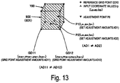
- FIG. 13 is a diagram schematically illustrating an example where, in a case where set adjustment amounts for a first adjustment point are different from set adjustment amounts for a second adjustment point, grid point adjustment amounts for a first reference grid point are made different from grid point adjustment amounts for a second reference grid point.
- FIG. 14 is a diagram schematically illustrating an example where grid point adjustment amounts for a reference grid point are determined to be average values of set adjustment amounts for a plurality of adjustment points accepted within an interpolation range.
- FIGS. 1 to 14 An overview of the technique included in the invention will be described with reference to examples illustrated in FIGS. 1 to 14 .
- the drawings of the present application schematically illustrate the examples, that an enlargement factor in each direction illustrated in each drawing may vary among the drawings, and that the drawings may not be consistent with one another.
- the elements of the technique are not limited to specific examples illustrated with reference numerals.
- Min to Max means a minimum value Min or greater and a maximum value Max or less.
- a color conversion table adjustment method is a color conversion table adjustment method causing a computer (e.g., a host apparatus 100 ) to execute a process for adjusting a color conversion table 601 representing a correspondence relationship between coordinate values in an input color space CS 4 and coordinate values in an output color space CS 5 for a plurality of grid points GD 0 , the color conversion table adjustment method including an adjustment point acceptance step ST 1 , a set adjustment amount acquisition step ST 2 , a grid point adjustment amount determination step ST 3 , and an adjustment step ST 4 .
- a computer e.g., a host apparatus 100
- the color conversion table adjustment method including an adjustment point acceptance step ST 1 , a set adjustment amount acquisition step ST 2 , a grid point adjustment amount determination step ST 3 , and an adjustment step ST 4 .
- the adjustment point acceptance step ST 1 it is possible to accept a plurality of adjustment points P 0 within an interpolation range 700 defined by a plurality of reference grid points GD 10 included in the plurality of grid points GD 0 in the color conversion table 601 and referenced when output coordinate values in the output color space CS 5 are interpolated, the interpolation range 700 dividing the input color space CS 4 .
- the set adjustment amount acquisition step ST 2 includes acquiring set adjustment amounts AD 0 representing amounts of adjustment for the accepted adjustment points P 0 .
- the grid point adjustment amount determination step ST 3 includes determining, by using the set adjustment amounts AD 0 for each of the adjustment points P 0 , grid point adjustment amounts AD 10 representing amounts of adjustment for the plurality of reference grid points GD 10 in a case where the plurality of adjustment points P 0 are accepted within the interpolation range 700 .
- the adjustment step ST 4 includes adjusting the color conversion table 601 , based on the grid point adjustment amounts AD 10 .
- a plurality of adjustment points P 0 may be set within the same interpolation range 700 .
- the set adjustment amounts AD 0 for each of the adjustment points P 0 are used to determine the grid point adjustment amounts AD 10 for the plurality of reference grid points GD 10 , thus adjusting the color conversion table 601 . Consequently, adjustment amounts for one point and adjustment amounts for another point within the same interpolation range 700 in the color conversion table 601 can be made closer to a user's intention. This enables accurate adjustment even in a case where a plurality of adjustment points are close to one another.
- Aspect 1 can therefore provide a color conversion table adjustment method improving the color reproduction accuracy of the to-be-adjusted color conversion table.
- Examples of the input color space include a CMYK color space, a CMY color space, an RGB color space, a CIE Lab color space, and CIE XYZ color space. Note that R means red, G means green, and B means blue.
- Examples of the output color space also include a CMYK color space, a CMY color space, an RGB color space, a CIE Lab color space, and CIE XYZ color space.
- Examples of the color conversion table include an A2B table and a B2A table included in an ICC profile, a device link table, and a color conversion table integrated into a printer driver.
- the interpolation range is determined by the reference grid points referenced when the output coordinate values are interpolated.
- the interpolation range is, for tetrahedral interpolation, a tetrahedron including four reference grid points as vertexes and, for hexahedral interpolation, a hexahedron including eight reference grid point as vertexes.
- a first adjustment point P 1 and a second adjustment point P 2 are two adjustment points P 0 located at different positions and included in the plurality of adjustment points P 0 accepted within the interpolation range 700
- a first reference grid point GD 11 and a second reference grid point GD 12 are two reference grid points GD 10 located at different positions and included in the plurality of reference grid points GD 10 .
- the grid point adjustment amounts AD 11 for the first reference grid point GD 11 may be made different from the grid point adjustment amounts AD 12 for the second reference grid point GD 12 to determine the grid point adjustment amounts AD 10 for the plurality of reference grid points GD 10 .
- the grid point adjustment amount determination step ST 3 may include using values representing the positions of the plurality of adjustment points P 0 within the interpolation range 700 and the set adjustment amounts AD 0 to determine the grid point adjustment amounts AD 10 for the plurality of reference grid points GD 10 .
- the positions of the plurality of adjustment points P 0 within the interpolation range 700 are reflected in the grid point adjustment amounts AD 10 . This allows provision of a suitable technique improving the color reproduction accuracy of the to-be-adjusted color conversion table.
- the grid point adjustment amount determination step ST 3 may include determining, in the virtual space SP 0 , data representing a hyperplane adapted to positions with coordinates corresponding to the m components and the set adjustment amounts AD 0 for the plurality of adjustment points P 0 accepted within the interpolation range 700 .
- the grid point adjustment amount determining step ST 3 may include determining the grid point adjustment amounts AD 10 to be the adjustment amounts AD satisfying the m components for the reference grid points GD 10 in the hyperplane, based on data representing the hyperplane.
- the positions of the plurality of adjustment points P 0 within the interpolation range 700 are more accurately reflected in the grid point adjustment amounts AD 10 . This allows provision of a more suitable technique improving the color reproduction accuracy of the to-be-adjusted color conversion table.
- the hyperplane is a concept of generalizing, to higher dimensions, the concept of a two-dimensional plane vs. a three-dimensional space, and means an n ⁇ 1-dimensional partial space of an n-dimensional vector space (in this case, n is an integer of 2 or larger).
- One hyperplane has the property of dividing the whole space into two half spaces.
- the grid point adjustment amount determination step ST 3 may include determining data representing the hyperplane passing through positions with coordinates corresponding to the m components and the set adjustment amounts AD 0 for the plurality of adjustment points P 0 in the virtual space SP 0 in a case where 2 or more and m+1 or less adjustment points P 0 are accepted within the interpolation range 700 .
- the hyperplane passing through positions corresponding to the 2 or more and m+1 or less adjustment points is included in the hyperplane adapted to positions with coordinates corresponding to the m components and the set adjustment amounts for the plurality of adjustment points in Aspect 4.
- Aspect 5 allows provision of a more suitable technique improving the color reproduction accuracy of the to-be-adjusted color conversion table in a case where m+1 or less adjustment points are accepted within the interpolation range.
- the grid point adjustment amount determination step ST 3 may include using the least squares method to determine data representing the hyperplane in the virtual space SP 0 , in a case where m+2 or more adjustment points P 0 are accepted within the interpolation range 700 .
- the hyperplane determined by the least squares method is included in the hyperplane adapted to positions with coordinates corresponding to the m components and the set adjustment amounts for the plurality of adjustment points in Aspect 4.
- Aspect 6 allows provision of a more suitable technique improving the color reproduction accuracy of the to-be-adjusted color conversion table in a case where m+2 or more adjustment points P 0 are accepted within the interpolation range.
- the grid point adjustment amount determination step may include determining data representing the hyperplane by using, instead of the least squares method, any one of maximum likelihood estimation, Random Sampling Consensus (RANSAC), and M-estimation.
- Aspect 6 also allows provision of a more suitable technique improving the color reproduction accuracy of the to-be-adjusted color conversion table in a case where m+2 or more adjustment points are accepted within the interpolation range.
- the grid point adjustment amount determination step ST 3 may include determining the grid point adjustment amounts AD 10 to be average values of the set adjustment amounts AD 0 for the plurality of reference grid points GD 10 accepted within the interpolation range 700 .
- Aspect 7 can also provide a suitable technique improving the color reproduction accuracy of a to-be-adjusted color conversion table.
- a color conversion table adjustment method is a color conversion table adjustment method causing a computer (e.g., the host apparatus 100 ) to execute a process for adjusting a color conversion table 601 representing the correspondence relationship between coordinate values in an input color space CS 4 and coordinate values in an output color space CS 5 for a plurality of grid points GD 0 , the color conversion table adjustment method including a set adjustment amount acquisition step ST 2 , a grid point adjustment amount determination step ST 3 , and an adjustment step ST 4 .
- the set adjustment amount acquisition step ST 2 includes acquiring set adjustment amounts AD 0 representing amounts of adjustment for a plurality of adjustment points P 0 present within an interpolation range 700 defined by a plurality of reference grid points GD 10 included in the plurality of grid points GD 0 in the color conversion table 601 and referenced when output coordinate values in the output color space CS 5 are interpolated, the interpolation range 700 dividing the input color space CS 4 .
- the grid point adjustment amount determination step ST 3 includes determining, by using the set adjustment amounts AD 0 , grid point adjustment amounts AD 10 representing amounts of adjustment for the plurality of reference grid points GD 10 .
- the adjustment step ST 4 includes adjusting the color conversion table 601 , based on the grid point adjustment amounts AD 10 .
- a first adjustment point P 1 and a second adjustment point P 2 are two adjustment points P 0 located at different positions and included in the plurality of adjustment points P 0 accepted within the interpolation range 700
- a first reference grid point GD 11 and a second reference grid point GD 12 are two reference grid points GD 10 located at different positions and included in the plurality of reference grid points GD 10 .
- the grid point adjustment amounts AD 11 for the first reference grid point GD 11 are made different from the grid point adjustment amounts AD 12 for the second reference grid point GD 12 to determine the grid point adjustment amounts AD 10 for the plurality of reference grid points GD 10 .
- the set adjustment amounts AD 0 for each of the plurality of adjustment points P 0 are used to determine the grid point adjustment amounts AD 10 for the plurality of reference grid points GD 10 , thus adjusting the color conversion table 601 .
- the grid point adjustment amounts AD 11 for the first reference grid point GD 11 are different from the grid point adjustment amounts AD 12 for the second reference grid point GD 12 .
- adjustment amounts for one point and adjustment amounts for another point within the same interpolation range 700 in the color conversion table 601 can be made closer to a user's intention. This enables accurate adjustment even in a case where a plurality of adjustment points are close to one another.
- Aspect 8 can provide a color conversion table adjustment method improving the color reproduction accuracy of the to-be-adjusted color conversion table.
- a color conversion table adjustment method is a color conversion table adjustment method causing a computer (e.g., the host apparatus 100 ) to execute a process for adjusting a color conversion table 601 representing the correspondence relationship between coordinate values in an input color space CS 4 and coordinate values in an output color space CS 5 for a plurality of grid points GD 0 , the color conversion table adjustment method including a set adjustment amount acquisition step ST 2 , a grid point adjustment amount determination step ST 3 , and an adjustment step ST 4 .
- the set adjustment amount acquisition step ST 2 includes acquiring set adjustment amounts AD 0 representing amounts of adjustment for a plurality of adjustment points P 0 present within an interpolation range 700 defined by a plurality of reference grid points GD 10 included in the plurality of grid points GD 0 in the color conversion table 601 and referenced when output coordinate values in the output color space CS 5 are interpolated, the interpolation range 700 dividing the input color space CS 4 .
- the grid point adjustment amount determination step ST 3 includes determining grid point adjustment amounts AD 10 representing amounts of adjustment for the plurality of reference grid points GD 10 to be average values of the set adjustment amounts AD 0 for the plurality of adjustment points P 0 accepted within the interpolation range 700 .
- the adjustment step ST 4 includes adjusting the color conversion table 601 , based on the grid point adjustment amounts AD 10 .
- the grid point adjustment amounts AD 10 are determined to be the average values of the set adjustment amounts AD 0 for each of the plurality of adjustment points P 0 present within the same interpolation range 700 , thus adjusting the color conversion table 601 .
- Aspect 9 can provide a color conversion table adjustment method improving the color reproduction accuracy of the to-be-adjusted color conversion table.
- a color conversion table adjustment program PRO causes a computer (e.g., the host apparatus 100 ) to implement functions corresponding to the steps of Aspects 1 to 7, i.e., an adjustment point acceptance function FU 1 corresponding to the adjustment point acceptance step ST 1 , a set adjustment amount acquisition function FU 2 corresponding to the set adjustment amount acquisition step ST 2 , a grid point adjustment amount determination function FU 3 corresponding to the grid point adjustment amount determination step ST 3 , and an adjustment function FU 4 corresponding to the adjustment step ST 4 .
- Aspect 10 can provide a color conversion table adjustment program improving the color reproduction accuracy of the to-be-adjusted color conversion table.
- a color conversion table adjustment program PRO causes a computer (e.g., the host apparatus 100 ) to implement functions FU 2 , FU 3 , and FU 4 corresponding to the steps ST 2 , ST 3 , and ST 4 of Aspect 8.
- Aspect 11 can also provide a color conversion table adjustment program improving the color reproduction accuracy of the to-be-adjusted color conversion table 601 .
- a color conversion table adjustment program PRO causes a computer (e.g., the host apparatus 100 ) to implement functions FU 2 , FU 3 , and FU 4 corresponding to the steps ST 2 , ST 3 , and ST 4 of Aspect 9.
- Aspect 12 can also provide a color conversion table adjustment program improving the color reproduction accuracy of the to-be-adjusted color conversion table.
- a color conversion table adjustment apparatus (e.g., the host apparatus 100 ) according to Aspect 13 of the technique includes an adjustment point acceptance unit U 1 corresponding to the adjustment point acceptance step ST 1 , a set adjustment amount acquisition unit U 2 corresponding to the set adjustment amount acquisition step ST 2 , a grid point adjustment amount determination unit U 3 corresponding to the grid point adjustment amount determination step ST 3 , and an adjustment function U 4 corresponding to the adjustment step ST 4 .
- Aspect 13 can provide a color conversion table adjustment apparatus improving the color reproduction accuracy of the to-be-adjusted color conversion table 601 .
- a color conversion table adjustment apparatus (e.g., the host apparatus 100 ) according to Aspect 14 of the technique includes units corresponding to the steps ST 2 , ST 3 and ST 4 of Aspect 8, i.e., a set adjustment amount acquisition unit U 2 , a grid point adjustment amount determination unit U 3 , and an adjustment function U 4 .
- Aspect 14 can also provide a color conversion table adjustment apparatus improving the color reproduction accuracy of the to-be-adjusted color conversion table 601 .
- a color conversion table adjustment apparatus (e.g., the host apparatus 100 ) according to Aspect 15 of the technique includes units corresponding to the steps ST 2 , ST 3 and ST 4 of Aspect 9, i.e., a set adjustment amount acquisition unit U 2 , a grid point adjustment amount determination unit U 3 , and an adjustment function U 4 .
- Aspect 15 can also provide a color conversion table adjustment apparatus improving the color reproduction accuracy of the to-be-adjusted color conversion table 601 .
- a color conversion table adjustment system SY 1 according to Aspect 16 of the technique includes a printing apparatus (for example, a printer 200 ) for printing a color chart including patches, a colorimetric apparatus 120 executing a colorimetric process on the patches, and the units of any one of Aspects 13 to 15.
- Aspect 16 can provide a color conversion table adjustment system improving the color reproduction accuracy of the to-be-adjusted color conversion table.
- the technique is applicable to a control method for a color conversion table adjustment apparatus, a composite system including the color conversion table adjustment apparatus, a control method for the composite system, a control program for the color conversion table adjustment apparatus, a control program for the composite system, a computer readable medium recording a color conversion table adjustment program and the control programs, and the like.
- the above-described apparatus may include a plurality of separate units.
- FIG. 1 schematically illustrates a configuration example of a color conversion table adjustment system including a color conversion table adjustment apparatus.
- a color conversion table adjustment system SY 1 illustrated in FIG. 1 includes the host apparatus 100 (an example of the color conversion table adjustment apparatus), a display apparatus 130 , the colorimetric apparatus 120 , and an ink jet-type printer 200 .
- a Central Processing Unit (CPU) 111 a Read Only Memory (ROM) 112 , a Random Access Memory (RAM) 113 , a storage device 114 , an input device 115 , a communication interface (I/F) 118 , a colorimetric apparatus I/F 119 , and the like are connected to one another, to be able to output and receive information to and from one another.
- the ROM 112 , the RAM 113 , and the storage device 114 are memories, and at least the ROM 112 and the RAM 113 are semiconductor memories.
- the display apparatus 130 displays a screen corresponding to display data from the host apparatus 100 , based on the display data.
- a liquid crystal display panel or the like may be used for the display apparatus 130 .
- the storage device 114 stores an operating system (OS) not illustrated in the drawings, a color conversion table adjustment program PRO, a profile 500 , and the like.
- the OS, the color conversion table adjustment program PRO, the profile 500 , and the like are read into the RAM 113 when appropriate, to be used for a process for adjusting the profile 500 .
- the profile 500 is a generic term for an input profile 610 , an output profile 620 , and a device link profile 630 .
- At least one of the RAM 113 and the storage device 114 stores various pieces of information, for example, the input profile 610 , the output profile 620 , the device link profile 630 , and an adjustment history not illustrated in the drawings.
- the storage device 114 may be a nonvolatile semiconductor memory such as a flash memory, a magnetic storage device such as a hard disk, or the like.
- the input device 115 may be a pointing device, a hard key including a keyboard, a touch panel attached to a surface of a display panel, or the like.
- the communication I/F 118 is connected to a communication I/F 210 in the printer 200 to output and receive information such as print data to and from the printer 200 .
- the colorimetric apparatus I/F 119 is connected to the colorimetric apparatus 120 to acquire colorimetric data including colorimetric values, from the colorimetric apparatus 120 .
- Standards to which the I/Fs 118 , 119 , and 210 conform to may include Universal Serial Bus (USB), near-field communication, and the like.
- Communication through the communication I/Fs 118 , 119 , and 210 may be wired or wireless or may be network communication such as through a Local Area Network (LAN) or the Internet.
- LAN Local Area Network
- the colorimetric apparatus 120 is capable of executing a colorimetric process on each color patch formed on a print substrate that is an example of a medium on which a color chart is formed, to output a colorimetric value.
- the patch is also referred to as a color chip.
- the colorimetric value is defined as a value representing, e.g., a lightness L and chromaticity coordinates a and b in a CIE Lab color space.
- the host apparatus 100 acquires colorimetric data from the colorimetric apparatus 120 to execute various processes.
- the color conversion table adjustment program PRO illustrated in FIG. 1 causes the host apparatus 100 to implement the adjustment point acceptance function FU 1 , the set adjustment amount acquisition function FU 2 , the grid point adjustment amount determination function FU 3 , and the adjustment function FU 4 .
- the CPU 111 of the host apparatus 100 reads, into the RAM 113 , the information stored in the storage device 114 when appropriate and executes the read program to perform various processes.
- the CPU 111 executes the color conversion table adjustment program PRO read into the RAM 113 to perform processes corresponding to the above-described functions FU 1 to FU 4 .
- the color conversion table adjustment program PRO causes the host apparatus 100 , which is a computer, to function as the adjustment point acceptance function U 1 , the set adjustment amount acquisition function U 2 , the grid point adjustment amount determination function U 3 , and the adjustment function U 4 .
- the host apparatus 100 executing the color conversion table adjustment program PRO implements the adjustment point acceptance step ST 1 , the set adjustment amount acquisition step ST 2 , the grid point adjustment amount determination step ST 3 , and the adjustment step ST 4 .
- the computer readable medium, which stores the color conversion table adjustment program PRO causing the computer to implement the above-described functions FU 1 to FU 4 is not limited to the storage device inside the host apparatus but may be a recording medium outside the host apparatus.
- examples of the host apparatus 100 include computers such as personal computers (including tablet terminals).
- computers such as personal computers (including tablet terminals).
- the display apparatus 130 , the colorimetric apparatus 120 , and the printer 200 are typically connected to the main body.
- a display apparatus-integrated computer such as a notebook personal computer
- the colorimetric apparatus 120 and the printer 200 are typically connected to the computer.
- the display apparatus-integrated host apparatus similarly outputs display data to the internal display apparatus.
- the host apparatus 100 may include all the components 111 to 119 in one housing but may include a plurality of devices separated from one another in such a manner that allows the devices to communicate with one another.
- the technique can be implemented even in a case where at least a part of the display apparatus 130 , the colorimetric apparatus 120 , and the printer 200 is included in the host apparatus 100 .
- the printer 200 (an example of an output device) illustrated in FIG. 1 is assumed to be an ink jet-type printer that discharges (injects) a cyan (C) ink, a magenta (M) ink, a yellow (Y) ink, and a black (K) ink from a recording head 220 as color materials to form an output image IMO corresponding to print data.
- the recording head 220 is fed with the cyan, magenta, yellow, and black (CMYK) inks from ink cartridges Cc, Cm, Cy, and Ck, respectively, to discharge CMYK ink droplets 280 through respective nozzles Nc, Nm, Ny, and Nk.
- CMYK cyan, magenta, yellow, and black
- the color management system illustrated in FIG. 2 causes a Raster Image Processor (RIP) 400 implemented in the host apparatus 100 to convert print document data DO into output data representing print colors cmyk p (cyan, magenta, yellow, and black), and causes the ink jet-type printer 200 to form printed matter.
- the print document data DO represents process colors CMYK in allowing a target color (C T ) to be reproduced using CMYK inks (color materials) in a target printing machine 300 , an example of a target apparatus for color matching.
- Color names in a color library 640 may be specified in the print document data DO.
- Pantone (trade name) color library may be employed, for example.
- the target printing machine 300 is assumed to be an offset printing machine but may be a photogravure press, a flexographic press, or the like.
- the target color C T is represented, for example, by a coordinate value (Lab value) in the CIE Lab color space.
- FIG. 2 illustrates how the target printing machine 300 prints, on the print substrate, a color chart CH 0 representing the target color C T and how the colorimetric apparatus executes a colorimetric process on each patch of the color chart CH 0 to acquire a colorimetric value Lab T .
- the process colors CMYK in correspond to the use amounts of the CMYK inks used in the target printing machine 300 , and represent coordinates in the CMYK color space depending on the target printing machine 300 .
- the RIP 400 illustrated in FIG. 2 includes the input profile 610 , the output profile 620 , the device link profile 630 , and the color library 640 .
- the input profile 610 is a file describing color properties of inks used in the target printing machine 300 .
- the output profile 620 is a file describing color properties of inks used in the ink jet-type printer 200 .
- the device link profile 630 is a combination profile of the input profile 610 and the output profile 620 .
- a data format of an ICC profile may be used.
- the process colors CMYK in in the print document data DO are converted into print colors cmyk p through a first conversion path involving passage though colors Labs in the Lab color space or a second conversion path avoiding the passage through the colors Labs in the Lab color space.
- the process colors CMYK in are converted into colors Lab s in the Lab color space in accordance with an A2B table 611 of the input profile 610 , and into print colors cmyk p in accordance with a B2A table 621 of the output profile 620 .
- the process colors CMYK in are converted into print colors cmyk p in accordance with a device link table 631 of the device link profile 630 .
- the A2B table 611 , the B2A table 621 , and the device link table 631 are collectively referred to as the color conversion table 601 .
- FIG. 2 illustrates how the printer 200 prints a color chart CH 1 representing the print colors cmyk p on the print substrate and how the colorimetric apparatus 120 executes a colorimetric process on each patch of the color chart CH 1 to acquire colorimetric values Lab p .
- the printer 200 can reproduce the print colors cmyk p on the printed matter.
- the print colors are not limited to a total of four colors, CMYK.
- the RIP 400 may reference the color library 640 to convert the color names into colors Lab s in the Lab color space.
- the RIP 400 also includes an input profile for a conversion between coordinate values in the Lab color space and process colors other than the process colors CMYK in , e.g., process colors (denoted by CMY in ) representing the use amounts of color materials of only three primary colors CMY corresponding to subtractive color mixture or process colors (denoted by RGB in ) representing the intensities of three primary colors of red (R), green (G), and blue (B) corresponding to additive color mixture. Therefore, the RIP 400 can convert the process colors CMY in , the process colors RGB in , or the like into print colors cmyk p via the Lab color space. In addition, the RIP 400 can receive colors Lab s in the Lab color space to convert the colors into the corresponding print color cmyk p .
- the ink jet-type printer 200 can reproduce colors similar to colors reproduced by the target printing machine 300 .
- expected colors may fail to be reproduced due to an error in the profile, a color measurement error, a fluctuation in the printer, and the like.
- modifications to the profiles 610 , 620 and 630 increase a conversion accuracy of the target color.
- FIG. 3 schematically illustrates a relationship among the input profile 610 , the output profile 620 , and the device link profile 630 .
- the input profile 610 is data specifying a correspondence relationship between CMYK values (C i , M i , Y i , K i ) in the CMYK color space (an example of the first device dependent color space CS 1 ) corresponding to the inks used in the target printing machine 300 and Lab values (L i , a i , b i ) in the Lab color space (an example of the Profile Connection Space (PCS) CS 3 ).
- PCS Profile Connection Space
- grid points GD 1 in the A2B table 611 are typically arranged in the CMYK color space at substantially equal intervals in a C axis direction, an M axis direction, a Y axis direction, and a K axis direction.
- the variable i is a variable identifying each grid point GD 1 set in the CMYK color space (CS 1 ).
- the CMYK values are an example of first coordinate values.
- the Lab values are an example of device independent coordinate values. In a case where only the input profile 610 is used, the CMYK color space (CS 1 ) is an example of an input color space CS 4 , and the Lab color space (CS 3 ) is an example of an output color space CS 5 .
- the first device dependent color space is also referred to as a first color space.
- the output profile 620 is data specifying a correspondence relationship between Lab values (L j , a j , b j ) in the Lab color space (CS 3 ) and cmyk values (c j , m j , y j , k j ) in the cmyk color space (an example of the second device dependent color space CS 2 ) corresponding to the inks used in the ink jet-type printer 200 .
- grid points GD 2 in the B2A table 621 are typically arranged in the Lab color space at substantially equal intervals in an L axis direction, an a axis direction, and a b axis direction.
- the variable j is a variable identifying each grid point GD 2 set in the Lab color space (CS 3 ).
- the expression “cmyk color space” is used to distinguish the color space corresponding to the inks used in the printer 200 from the color space corresponding to the inks used in the target printing machine 300 .
- the cmyk values are an example of second coordinate values.
- the Lab color space (CS 3 ) is an example of the input color space CS 4
- the cmyk color space (CS 2 ) is an example of the output color space CS 5 .
- a color reproduction region of the output color (cmyk p ) represented by the cmyk values depends on the printer 200 .
- the second device dependent color space is also referred to as a second color space.
- the device link profile 630 is data specifying a correspondence relationship between CMYK values (C i , M i , Y i , K i ) in the CMYK color space (CS 1 ) and cmyk values (c i , m i , y i , k i ) in the cmyk color space (CS 2 ).
- each grid point GD 1 in the device link table 631 is a corresponding grid point in the A2B table 611 of the input profile 610 .
- the variable i is a variable identifying each grid point GD 1 set in the CMYK color space (CS 1 ).
- each grid point in the device link table 631 may be different from a corresponding grid point GD 1 in the A2B table 611 of the input profile 610 .
- the device link profile 630 is acquired by merging the input profile 610 (particularly the A2B table 611 ) and the output profile 620 (particularly the B2A table 621 ).
- the CMYK color space (CS 1 ) is an example of the input color space CS 4
- the cmyk color space (CS 2 ) is an example of the output color space CS 5 .
- the color conversion table 601 included in each of the profiles 610 , 620 , and 630 is not limited to a single conversion table but may be a combination of a plurality of conversion tables such as a combination of a one-dimensional conversion table, a three- or four-dimensional conversion table, and a one-dimensional table.
- the color conversion tables 601 illustrated in FIG. 3 may directly illustrate three- or four-dimensional conversion tables included in the profiles 610 , 620 , and 630 or illustrate a combination of a plurality of conversion tables included in the profiles 610 , 620 , and 630 .
- the grid points mean virtual points arranged in the input color space, and output coordinate values corresponding to the position of each grid point in the input color space are assumed to be stored at the grid point.
- the technique includes not only even arrangement of a plurality of grid points in the input color space but also uneven arrangement of a plurality of grid points in the input color space.
- FIG. 4 schematically illustrates the structure of the profile 500 , particularly the input profile 610 and the output profile 620 .
- the profile 500 illustrated in FIG. 4 is an ICC profile and includes a profile header 510 and a tag table 520 .
- the profile 500 includes tags 521 that are information used to convert color information between the PCS and the device dependent color space.
- the tags 521 may include private tags 523 used to customize the profile 500 .
- A2Bx tags for the devices ( 300 and 200 ) include, as element data 530 , a color conversion table used to convert the device dependent color space (CMYK color space or cmyk color space) into the Lab color space.
- B2Ax tags for the devices ( 300 and 200 ) include, as the element data 530 , a color conversion table used to convert the Lab color space into the device dependent color space (CMYK color space or cmyk color space).
- An A2B0 tag and a B2A0 tag illustrated in FIG. 4 are information used for a Perceptual color conversion.
- the perceptual color conversion focuses on tone reproduction and is thus mostly used for a conversion of photographic images with a wide color gamut.
- the A2B1 tag and the B2A1 tag illustrated in FIG. 4 are information used for a media-relative colorimetric color conversion or an absolute colorimetric color conversion.
- the colorimetric color conversion is faithful to colorimetric values, and is thus mostly used for a conversion for digital-proof color calibration output for which accurate color matching is indispensable.
- An A2B2 tag and a B2A2 tag illustrated in FIG. 4 are information used for a color conversion focusing on saturation.
- the color conversion focusing on saturation focuses more on saturation of colors than on the accuracy of hue and is mostly used for a conversion of graph display and the like in business graphics.
- FIG. 5 is a block diagram schematically illustrating the structure of the B2A table 621 of the output profile 620 as a structure example of a conversion table of a profile.
- a lower portion of FIG. 5 schematically illustrates the positions of grid points GD 2 in the Lab color space (CS 3 ).
- the grid points GD 2 in the three-dimensional B2A table 621 are typically arranged in the Lab color space at substantially equal intervals in the L axis direction, the a axis direction, and the b axis direction.
- FIG. 5 is a block diagram schematically illustrating the structure of the B2A table 621 of the output profile 620 as a structure example of a conversion table of a profile.
- a lower portion of FIG. 5 schematically illustrates the positions of grid points GD 2 in the Lab color space (CS 3 ).
- the grid points GD 2 in the three-dimensional B2A table 621 are typically arranged in the Lab color space at substantially equal intervals in the L axis direction, the a axi
- GL denotes the number of grid points GD 2 in the L axis direction
- Ga denotes the number of grid points GD 2 in the a axis direction
- Gb denotes the number of grid points GD 2 in the b axis direction.
- the number of grid points in B2A table 621 is thus GL ⁇ Ga ⁇ Gb.
- at least any of the numbers of grid points in the respective axis directions may be different from GL, Ga, and Gb.
- the grid points GD 1 in the A2B table 611 of the input profile 610 and in the device link table 631 of the device link profile 630 are typically arranged in the CMYK color space (CS 1 ) at substantially equal intervals in the C axis direction, the M axis direction, the Y axis direction, and the K axis direction.
- the numbers of grid points GD 1 in the C, M, Y, and K axis directions are respectively denoted by Gc, Gm, Gy, and Gk
- Gc ⁇ Gm ⁇ Gy ⁇ Gk grid points are present in the four-dimensional A2B table 611 and in the device link table 631 .
- at least any of the numbers of grid points in the respective axis directions may be different from Gc, Gm, Gy, and Gk.
- FIGS. 6A to 6D are diagrams for schematically illustrating an example of N-point interpolation (N is an integer of 4 or larger) in the three-dimensional space.
- N is an integer of 4 or larger
- blank circles represent the grid points GD 0 in the color conversion table 601
- filled circles represent reference grid points GD 10 that are included in the plurality of grid points GD 0 and that are referenced during interpolation of output coordinate values in the output color space CS 5 .
- An upward blank triangular mark represents the position of input coordinate values Ip
- downward filled triangular marks represent adjustment points P 0 described below.
- An interpolation range 700 that is a range within which output coordinate values corresponding to the input coordinate values Ip are interpolated is a range defined by a plurality of reference grid points surrounding the input coordinate values Ip, to divide the input color space CS 4 .
- the interpolation range corresponds to each shaded polyhedron in FIGS. 6A to 6D .
- N-point interpolation refers to an interpolation calculation based on the output coordinate values of the reference grid points GD 10 and weight coefficients when output coordinate values are determined that correspond to the input coordinate values Ip of position included in the interpolation range 700 .
- the weight coefficient for each of the reference grid points GD 10 may be determined using a well-known method. For example, assume that a distance from the position of the input coordinate values Ip to each reference grid point GD 10 is denoted by Li.
- the variable i in this case is a variable that identifies the reference grid point GD 10 .
- the sum of the reciprocals of the distances 1/Li is denoted by S 1/Li and the weight for each reference grid point GD 10 is denoted by 1/Li/S 1/Li , and the sums of the output coordinate values of the reference grid points GD 10 multiplied by the weights may be determined to be the output coordinate values corresponding to the input coordinate values Ip.
- the weight coefficient may correspond to, e.g., a volume ratio of solids resulting from division, by planes passing through the position of the input coordinate values Ip, of a solid with the reference grid points GD 10 as vertexes.
- rectangular interpolation that is 8-point interpolation may include dividing the grid 900 into eight rectangular parallelepipeds by planes orthogonal to the axis directions of respective axes of the input color space, and determining the weight coefficient for each of the reference grid points GD 10 to be the volume ratio between the diagonally located resultant rectangular parallelepipeds.
- FIG. 7 is a diagram for schematically illustrating an example of N-point interpolation for a four-dimensional color conversion table.
- FIG. 7 An upper portion of FIG. 7 illustrates, by a filled triangular mark, the position of a set of input coordinate values Ip (Cp, Mp, Yp, Kp) on the K axis in the CMYK color space (CS 1 ).
- the positions of grid points GD 0 adjacent to the set of input coordinate values Ip in the K axis direction are denoted by K1 and K2. In this case, K1 ⁇ K2.
- K fixed to K1 and K2 allows assumption of a three-dimensional virtual space expressed by the C axis, the M axis, and the Y axis.
- this calculation may use the weight coefficients and the output coordinate values of the four reference grid points GD 10 at the vertexes of the trigonal pyramid (interpolation range 700 ) resulting from division of the grid 900 into six pieces, as described above.
- the result of the calculation is to be used as Lab values (L1, a1, b1).
- This calculation may also use the weight coefficients and the output coordinate values of the four reference grid points GD 10 at the vertexes of the trigonal pyramid (interpolation range 700 ) resulting from division of the grid 900 into six pieces, as described above.
- the result of the calculation is assumed to be Lab values (L2, a2, b2).
- the final output coordinate values (Lp, ap, bp) corresponding to the input coordinate values Ip may be determined by apply weights corresponding to the position of the input coordinate values Ip on the K axis.
- Lp (1 ⁇ Kr ) ⁇ L 1+ Kr ⁇ L 2
- ap (1 ⁇ Kr ) ⁇ a 1+ Kr ⁇ a 2
- bp (1 ⁇ Kr ) ⁇ b 1+ Kr ⁇ b 2
- an interpolation calculation may be executed by selecting N reference grid points surrounding the input coordinate values Ip in the four-dimensional color conversion table.
- the four-dimensional color conversion table such as the device link table 631 or the A2B table of the output profile 620 may similarly be used for the interpolation calculation.
- FIG. 8 illustrates a color conversion table adjustment process to be executed by the host apparatus 100 illustrated in FIG. 1 .
- the host apparatus 100 executes a plurality of processes in parallel based on multitasking. The processes illustrated in this specific example may be properly changed, e.g., reordered.
- step S 111 corresponds to the adjustment point acceptance step ST 1 , the adjustment point acceptance function FU 1 , and the adjustment point acceptance unit U 1 .
- Step S 112 and S 120 correspond to the set adjustment amount acquisition step ST 2 , the set adjustment amount acquisition function FU 2 , and the set adjustment amount acquisition unit U 2 .
- Step S 122 corresponds to the grid point adjustment amount determination step ST 3 , the grid point adjustment amount determination function FU 3 , and the grid point adjustment amount determination unit U 3 .
- Step S 124 corresponds to the adjustment step ST 4 , the adjustment function FU 4 , and the adjustment unit U 4 .
- the term “step” is omitted from the description below.
- FIG. 9 illustrates an example of a User Interface (UI) screen 800 displayed in step S 102 in FIG. 8 .
- UI User Interface
- the host apparatus 100 causes the display apparatus 130 to display the UI screen 800 , illustrated in FIG. 9 (S 102 ).
- the UI screen 800 includes an input profile selection section 811 , an output profile selection section 812 , a device link profile selection section 813 , a to-be-adjusted profile specification section 820 , a to-be-adjusted color space selection section 830 , a target acceptance area 840 , a “specify based on image” button 841 , an add button 842 , a delete button 843 , an adjustment data selection section 845 , a chart print button 846 , a colorimetry button 847 , an intent specification section 860 , an adjustment execute button 870 , a history load button 881 , and a history save button 882 .
- the host apparatus 100 accepts operations on any of the above-described sections and buttons through the input device 115 (S 110 ), and when accepting an operation on the adjustment execution button 870 , advances the process to S 120 .
- the process in S 110 includes the following processes S 111 and S 112 .
- the host apparatus 100 can cause the display apparatus 130 to display a list of the input profiles 610 stored in the storage device 114 .
- the host apparatus 100 accepts, from the input device 115 , one input profile in the displayed list of the input profiles 610 for color conversion as a profile for color conversion.
- the host apparatus 100 can cause the display apparatus 130 to display a list of the output profiles 620 stored in the storage device 114 .
- the host apparatus 100 accepts, from the input device 115 , one output profile in the displayed list of the output profiles 620 as a profile for color conversion.
- the host apparatus 100 can cause the display apparatus 130 to display a list of the device link profiles 630 stored in the storage device 114 .
- the host apparatus 100 accepts, from the input device 115 , one device link profile in the displayed list of the device link profiles 630 as a profile for color conversion.
- the host apparatus 100 accepts, from the input device 115 , one of the input profile 610 , the output profile 620 , and the device link profile 630 as a to-be-adjusted profile 550 .
- the host apparatus 100 may disable selection of a profile in any of the selection sections 811 to 813 in which no operation has been accepted.
- the host apparatus 100 accepts, from the input device 115 , one of the CMYK color space (CS 1 ), the cmyk color space (CS 2 ), and the Lab color space (CS 3 ) as a to-be-adjusted color space.
- the host apparatus 100 may disable selection of the cmyk color space (CS 2 ) in a case where an operation has been accepted only in the input profile selection section 811 and may disable selection of the CMYK color space (CS 1 ) in a case where an operation has been accepted only in the output profile selection section 812 .
- the host apparatus 100 executes a process for changing the input item of the target acceptance area 840 according to the selection in the to-be-adjusted color space selection section 830 . Furthermore, the host apparatus 100 executes a process for changing the input item of the target acceptance area 840 according to the selection in the adjustment data selection section 845 .
- the adjustment data selection section 845 either one of “absolute value” and “relative value” can be selected.
- the “absolute value” is an option allowing the adjustment target T 0 to be accepted as a coordinate value in the color space.
- the “relative value” is an option allowing the adjustment target T 0 to be accepted as a difference from the current coordinate value in the color space.
- the host apparatus 100 When accepting the “relative value” in the adjustment data selection section 845 , the host apparatus 100 causes an input section for the coordinate values ( ⁇ L, ⁇ a, ⁇ b) of the adjustment target T 0 , as relative values (denoted by ⁇ Lab T-p ) relative to the current coordinate values in the PCS CS 3 , to be displayed in the target acceptance area 840 , as illustrated in FIG. 9 . In this case, the host apparatus 100 accepts, in the input section, relative values ⁇ Lab T-p ( ⁇ L, ⁇ a, ⁇ b) of the adjustment target T 0 .
- the host apparatus 100 when accepting the “absolute value” in the adjustment data selection section 845 , the host apparatus 100 causes an input section for the coordinate values (denoted by T_L, T_a, T_b) of the adjustment target T 0 along with a display section for the current coordinate values (denoted by C_L, C_a, C_b) in the PCS CS 3 to be displayed in the target acceptance area 840 .
- the host apparatus 100 accepts, in the input section, absolute values (T_L, T_a, T_b) of the adjustment target T 0 .
- the host apparatus 100 When accepting the “relative value” in the adjustment data selection section 845 , the host apparatus 100 causes an input section for the coordinate values (denoted by ⁇ C, ⁇ M, ⁇ Y, ⁇ K) of the adjustment target T 0 as relative values (denoted by ⁇ CMYK T-p ) relative to the current coordinate values in the CMYK color space (CS 1 ), to be displayed in the target acceptance area 840 . In this case, the host apparatus 100 accepts, in the input section, relative values ⁇ CMYK T-p ( ⁇ C, ⁇ M, ⁇ Y, ⁇ K) of the adjustment target T 0 .
- the host apparatus 100 when accepting the “absolute value” in the adjustment data selection section 845 , the host apparatus 100 causes an input section for the coordinate values (denoted by T_C, T_M, T_Y, T_K) of the adjustment target T 0 along with a display section for the current coordinate values (denoted by C_C, C_M, C_Y, C_K) in the CMYK color space (CS 1 ) to be displayed in the target acceptance area 840 . In this case, the host apparatus 100 accepts, in the input section, absolute values (T_C, T_M, T_Y, T_K) of the adjustment target T 0 .
- the host apparatus 100 When accepting the “relative value” in the adjustment data selection section 845 , the host apparatus 100 causes an input section for the coordinate values (denoted by ⁇ c, ⁇ m, ⁇ y, ⁇ k) of the adjustment target T 0 as relative values (denoted by ⁇ cmyk T-p ) relative to the current coordinate values in the cmyk color space (CS 2 ) to be displayed in the target acceptance area 840 .
- the host apparatus 100 accepts, in the input section, relative values ⁇ cmyk T-p ( ⁇ c, ⁇ m, ⁇ y, ⁇ k) of the adjustment target T 0 .
- the host apparatus 100 when accepting the “absolute value” in the adjustment data selection section 845 , the host apparatus 100 causes an input section for the coordinate values (denoted by T_c, T_m, T_y, T_k) of the adjustment target T 0 along with a display section for the current coordinate values (denoted by C_c, C_m, C_y, C_k) in the cmyk color space (CS 2 ) to be displayed in the target acceptance area 840 . In this case, the host apparatus 100 accepts, in the input section, absolute values (T_c, T_m, T_y, T_k) of the adjustment target T 0 .
- the adjustment point P 0 for which the adjustment target T 0 is to be set is set in, e.g., the CMYK color space (CS 1 ).
- the host apparatus 100 when accepting an operation on the “specify based on image” button 841 in the UI screen 800 illustrated in FIG. 9 , the host apparatus 100 causes the display apparatus 130 to display a screen schematically depicting the CMYK color space (CS 1 ), and acquires CMYK values corresponding to an operation through the input device 115 to update the information of the adjustment target T 0 in the target acceptance area 840 .
- the host apparatus 100 When a new adjustment point P 0 is specified, the host apparatus 100 provides a corresponding ID (identification information) and causes the acquired CMYK values, Lab values obtained from the CMYK values, and the like to be displayed in the target acceptance area 840 in association with the ID.
- ID identification information
- the host apparatus 100 When the add button 842 is operated, the host apparatus 100 provides an additional ID, and adds, to the target acceptance area 840 , an input section corresponding to the added ID.
- the delete button 843 When the delete button 843 is operated, the host apparatus 100 accepts a specification of an ID to be deleted, and deletes the input section corresponding to the specified ID.
- the host apparatus 100 is capable of executing the adjustment point acceptance process of accepting the settings for the adjustment point P 0 (S 111 ) to accept a plurality of adjustment points P 0 within one interpolation range 700 .
- the host apparatus 100 When accepting an operation on the chart print button 846 , the host apparatus 100 generates print data of the color chart CH 1 with color patches each representing the color of corresponding adjustment point P 0 and transmits the print data to the printer 200 .
- the printer 200 receives the print data and then prints, on the print substrate ME 1 , the color chart CH 1 with the color patches each representing the color of corresponding adjustment point P 0 .
- the host apparatus 100 When accepting an operation on the colorimetry button 847 , the host apparatus 100 instructs the colorimetric apparatus 120 to execute a colorimetric process on each patch of the color chart CH 1 .
- the colorimetric apparatus 120 receives the instruction, then executes a colorimetric process on each patch of the color chart CH 1 , and transmits the colorimetric values (Lab p ) of each patch to the host apparatus 100 .
- the host apparatus 100 receives the colorimetric values (Lab p ) and may then cause the display apparatus 130 to display the colorimetric values (Lab p ) or cause the printer 200 to print the colorimetric values (Lab p ).
- a user may view the output colorimetric values (Lab p ) and input the adjustment target T 0 to the target acceptance area 840 .
- the host apparatus 100 may automatically input the colorimetric values (Lab p ) of each patch to an input section for the target T 0 .
- the host apparatus 100 may calculate differences between the components L, a, and b of the target colorimetric values Lab T and the components L, a, and b of the current colorimetric values Lab p and automatically input the differences to the input section for the target T 0 .
- the host apparatus 100 executes the target acceptance process of accepting an input of the adjustment target T 0 for each adjustment point P 0 (S 112 ).
- the host apparatus 100 When accepting an operation on the history load button 881 , the host apparatus 100 reads an adjustment history stored in the storage device 114 , and adds the adjustment history to the target acceptance area 840 . When an operation on the history save button 882 is accepted, the host apparatus 100 stores the information of the target acceptance area 840 in the storage device 114 as an adjustment history.
- the host apparatus 100 accepts, in the intent specification section 860 , a specification of a rendering intent for defining the correspondence relationship for the to-be-adjusted profile 550 .
- a plurality of specification items for the intent specification section 860 illustrated in FIG. 9 are three types of items: “Perceptual”, “Relative Colorimetric”, and “Saturation”.
- the specification items may include “Absolute Colorimetric”, or any of “Perceptual”, “Relative Colorimetric”, and “Saturation” may be omitted from the specification items.
- FIG. 9 illustrates an example where “Perceptual” is specified as a specified intent.
- the host apparatus 100 executes a process in S 120 and the subsequent steps in FIG. 8 .
- the host apparatus 100 uses, in the process in S 120 and the subsequent steps, information in the profile 500 based on a perceptual color conversion (e.g., the information indicated by the A2B0 tag and the B2A0 tag illustrated in FIG. 4 ).
- the host apparatus 100 uses, in the process in S 120 and the subsequent steps, information in the profile 500 based on a relative colorimetric color conversion (e.g., the information indicated by the A2B1 tag and the B2A1 tag illustrated in FIG. 4 ).
- a relative colorimetric color conversion e.g., the information indicated by the A2B1 tag and the B2A1 tag illustrated in FIG. 4
- saturation the host apparatus 100 uses, in the process in S 120 and the subsequent steps, information in the profile 500 based on a color conversion focusing on saturation (e.g., the information indicated by the A2B2 tag and the B2A2 tag illustrated in FIG. 4 ).
- the host apparatus 100 acquires set adjustment amounts AD 0 representing amounts of adjustment for each of the accepted adjustment points P 0 in the output color space CS 5 of the to-be-adjusted profile 550 (S 120 ).
- the output color space CS 5 is the Lab color space (CS 3 ).
- the host apparatus 100 thus acquires the set adjustment amounts AD 0 for the Lab color space (CS 3 ).
- the set adjustment amounts AD 0 are the relative values ⁇ Lab T-p ( ⁇ L, ⁇ a, ⁇ b) of the adjustment target T 0 .
- the absolute values (T_L, T_a, T_b) are accepted in the input section for the adjustment target T 0 .
- the relative values ⁇ Lab T-p (T_L ⁇ C_L, T_a ⁇ C_a, T_b ⁇ C_b) may be calculated.
- the set adjustment amounts AD 0 are obtained in accordance with the A2B table 611 of the input profile 610 .
- the current coordinate values (C_C, C_M, C_Y, C_K) of the adjustment point P 0 are converted into the current coordinate values (C_L, C_a, C_b) in the Lab color space (CS 3 ) in accordance with the A2B table 611 .
- the absolute values (T_C, T_M, T_Y, T_K) of the adjustment target T 0 are converted into the absolute values (T_L, T_a, T_b) in the Lab color space (CS 3 ) in accordance with the A2B table 611 .
- the set adjustment amounts AD 0 are the relative values ⁇ Lab T-p (T_L ⁇ C_L, T_a ⁇ C_a, T_b ⁇ C_b) of the adjustment target T 0 .
- the absolute values (C_C+ ⁇ C, C_M+ ⁇ M, C_Y+ ⁇ Y, C_K+ ⁇ K) may be calculated, and then, the set adjustment amounts AD 0 may be calculated as described above.
- the set adjustment amounts AD 0 are obtained in accordance with the A2B table of the output profile 620 .
- the current coordinate values (C_c, C_m, C_y, C_k) of the adjustment point P 0 are converted into the current coordinate values (C_L, C_a, C_b) in the Lab color space (CS 3 ) in accordance with the A2B table.
- the absolute values (T_c, T_m, T_y, T_k) of the adjustment target T 0 are converted into the absolute values (T_L, T_a, T_b) in the Lab color space (CS 3 ) in accordance with the A2B table.
- the set adjustment amounts AD 0 are the relative values ⁇ Lab T-p (T_L ⁇ C_L, T_a ⁇ C_a, T_b ⁇ C_b) of the adjustment target T 0 .
- the absolute values (C_c+ ⁇ c, C_m+ ⁇ m, C_y+ ⁇ y, C_k+ ⁇ k) may be calculated, and then, the set adjustment amounts AD 0 may be calculated as described above.
- the output color space CS 5 is the cmyk color space (CS 2 ).
- the host apparatus 100 thus acquires the set adjustment amounts AD 0 for the cmyk color space (CS 2 ).
- the set adjustment amounts AD 0 are the relative values ⁇ cmyk T-p ( ⁇ c, ⁇ m, ⁇ y, ⁇ k) of the adjustment target T 0 .
- the absolute values (T_c, T_m, T_y, T_k) are accepted in the input section for the adjustment target T 0 .
- the relative values ⁇ cmyk T-p (T_c ⁇ C_c, T_m ⁇ C_m, T_y ⁇ C_y, T_k ⁇ C_k) may be calculated.
- the set adjustment amounts AD 0 are obtained in accordance with the B2A table 621 of the output profile 620 .
- the current coordinate values (C_L, C_a, C_b) of the adjustment point P 0 are converted into the current coordinate values (C_c, C_m, C_y, C_k) in the cmyk color space (CS 2 ) in accordance with the B2A table 621 .
- the absolute values (T_L, T_a, T_b) of the adjustment target T 0 are converted into the absolute values (T_c, T_m, T_y, T_k) in the cmyk color space (CS 2 ) in accordance with the B2A table 621 .
- the set adjustment amounts AD 0 are the relative values ⁇ cmyk T-p (T_c ⁇ C_c, T_m ⁇ C_m, T_y ⁇ C_y, T_k ⁇ C_k) of the adjustment target T 0 .
- the absolute values (C_L+ ⁇ L, C_a+ ⁇ a, C_b+ ⁇ b) may be calculated, and then, the set adjustment amounts AD 0 may be calculated as described above.
- the set adjustment amounts AD 0 are obtained in accordance with the A2B table 611 of the input profile 610 and the B2A table 621 of the output profile 620 .
- the current coordinate values (C_C, C_M, C_Y, C_K) of the adjustment point P 0 are converted into the current coordinate values (C_c, C_m, C_y, C_k) in the cmyk color space (CS 2 ) in accordance with the A2B table 611 and the B2A table 621 .
- the absolute values (T_C, T_M, T_Y, T_K) of the adjustment target T 0 are converted into the absolute values (T_c, T_m, T_y, T_k) in the cmyk color space (CS 2 ) in accordance with the A2B table 611 and the B2A table 621 .
- the set adjustment amounts AD 0 are the relative values ⁇ cmyk T-p (T_c ⁇ C_c, T_m ⁇ C_m, T_y ⁇ C_y, T_k ⁇ C_k) of the adjustment target T 0 .
- the absolute values (C_C+ ⁇ C, C_M+ ⁇ M, C_Y+ ⁇ Y, C_K+ ⁇ K) may be calculated, and then, the set adjustment amounts AD 0 may be calculated as described above.
- the output color space CS 5 is the cmyk color space (CS 2 ).
- the host apparatus 100 thus acquires the set adjustment amounts AD 0 for the cmyk color space (CS 2 ).
- the set adjustment amounts AD 0 are the relative values ⁇ cmyk T-p ( ⁇ c, ⁇ m, ⁇ y, ⁇ k) of the adjustment target T 0 .
- the absolute values (T_c, T_m, T_y, T_k) are accepted in the input section for the adjustment target T 0 .
- the relative values ⁇ cmyk T-p (T_c ⁇ C_c, T_m ⁇ C_m, T_y ⁇ C_y, T_k ⁇ C_k) may be calculated.
- the set adjustment amounts AD 0 are obtained in accordance with the device link table 631 of the device link profile 630 .
- the current coordinate values (C_C, C_M, C_Y, C_K) of the adjustment point P 0 are converted into the current coordinate values (C_c, C_m, C_y, C_k) in the cmyk color space (CS 2 ) in accordance with the device link table 631 .
- the absolute values (T_C, T_M, T_Y, T_K) of the adjustment target T 0 are converted into the absolute values (T_c, T_m, T_y, T_k) in the cmyk color space (CS 2 ) in accordance with the device link table 631 .
- the set adjustment amounts AD 0 are the relative values ⁇ cmyk T-p (T_c ⁇ C_c, T_m ⁇ C_m, T_y ⁇ C_y, T_k ⁇ C_k) of the adjustment target T 0 .
- the absolute values (C_C+ ⁇ C, C_M+ ⁇ M, C_Y+ ⁇ Y, C_K+ ⁇ K) may be calculated, and then, the set adjustment amounts AD 0 may be calculated.
- the set adjustment point P 0 matches none of the grid points GD 0 in the color conversion table 601 of the to-be-adjusted profile 550 .
- a plurality of grid points surrounding the adjustment point P 0 are referenced.
- grid points referenced when the output coordinate values of the adjustment point P 0 are interpolated are referred to as reference grid points GD 10 .
- the host apparatus 100 acquires the set adjustment amounts AD 0 , the host apparatus 100 determines, by using the set adjustment amounts AD 0 for each adjustment point P 0 , grid point adjustment amounts AD 10 representing amounts of adjustment for each reference grid point GD 10 (S 122 ).
- the input color space CS 4 of the color conversion table 601 included in the to-be-adjusted profile 550 is typically three- or four-dimensional. However, for easy-to-understand description of the concept of algorithms, first, the input color space of the color conversion table is assumed to be one-dimensional.
- FIGS. 10A to 10C are diagrams schematically illustrating an example where the grid point adjustment amounts AD 10 are determined in a case where a color conversion table of the to-be-adjusted profile is assumed to be one-dimensional.
- the horizontal axis indicates a certain coordinate axis of the color conversion table 601
- the vertical axis indicates the adjustment amount AD representing the amount by which the value is adjusted.
- the horizontal axis is the L axis, the a axis, or the b axis.
- reference grid points GD 11 and GD 12 are illustrated as the reference grid points GD 10 located at the ends(vertexes) of the interpolation range 700
- adjustment points P 1 , P 2 , and P 3 are illustrated as adjustment points P 0 present within the interpolation range 700
- set adjustment amounts AD 1 , AD 2 , and AD 3 are respectively illustrated as set adjustment amounts AD 0 for the adjustment points P 1 , P 2 , and P 3 .
- the interpolation range 700 is on the coordinate axis between the reference grid points GD 11 and GD 12 .
- a two-dimensional plane including a one-dimensional coordinate axis and an additional coordinate axis for the adjustment amount AD corresponds to the virtual space SP 0 according to the technique.
- intersections between the line LN 1 with a slope of 0 and lines passing through the reference grid points GD 11 and GD 12 along the coordinate axis of the adjustment amount AD are determined, and the adjustment amounts AD for the intersections are determined to be the grid point adjustment amounts AD 10 .
- the line passing through the coordinates p 1 and p 2 is determined, intersections between the line LN 2 and lines passing through the reference grid points GD 11 and GD 12 along the coordinate axis of the adjustment amount AD are determined, and the adjustment amounts AD for the intersections are determined to be grid point adjustment amounts AD 11 and AD 12 .
- the interpolation range 700 includes three adjustment points P 1 , P 2 , and P 3 as illustrated in FIG. 10C .
- a line LN 3 compatible with the coordinates p 1 , p 2 , and p 3 are determined by the least squares method, intersections between the line LN 3 and lines passing through the reference grid points GD 11 and GD 12 along the coordinate axis of the adjustment amount AD are determined, and the adjustment amounts AD for the intersections are determined to be the grid point adjustment amounts AD 11 and AD 12 .
- the grid point adjustment amounts AD 11 and AD 12 may similarly be determined.
- the actual input color space CS 4 of the color conversion table 601 is typically three- or four-dimensional.
- an interpolation range 700 for dividing, defined by a plurality of reference grid points GD 10 surrounding the adjustment point P 0 as illustrated in FIGS. 6A to 6D is set to correspond to a linear interpolation range 700 illustrated in FIGS. 10A to 10 C.
- an interpolation range 700 defined by a plurality of reference grid points GD 10 surrounding the adjustment point P 0 in virtual three-dimensional spaces with fixed K values as illustrated in FIG. 7 is set to correspond to a linear interpolation range 700 illustrated in FIGS. 10A to 10C .
- the interpolation range 700 is a hexahedron with eight reference grid points GD 10 as vertexes as illustrated in FIG. 6D .
- the grid point adjustment amounts AD 10 may similarly be determined.
- the interpolation range 700 is expressed as a three-dimensional hyperplane.
- intersections between the hyperplane and lines passing through the reference grid points GD 10 along the coordinate axes of the adjustment amounts AD are determined, and then, the adjustment amounts AD for the intersections may be determined to be the grid point adjustment amounts AD 10 .
- FIG. 11 illustrates the grid point adjustment amount determination process executed in S 122 in FIG. 8 .
- the host apparatus 100 branches the process depending on the number of adjustment points P 0 accepted within the interpolation range 700 (S 202 ).
- the host apparatus 100 determines data representing a hyperplane passing through positions with coordinates corresponding to the m components and the set adjustment amounts AD 0 for each adjustment point P 0 in the virtual space SP 0 (S 204 to S 210 ), and advances the process to S 214 .
- the host apparatus 100 uses the least squares method to determine data representing a hyperplane in the virtual space SP 0 (S 212 ), and advances the process to S 214 .
- the adjustment amounts AD are denoted by w.
- P 0 may be used as an index to represent, as (x P0 , y P0 , z P0 , w P0 ), the coordinates (denoted by p 0 ) of the adjustment point P 0 in the virtual space SP 0 .
- x P0 , y P0 , and z P0 are values representing the position of the adjustment point P 0
- w P0 is the set adjustment amounts AD 0 .
- a in this case is a coefficient for the component x
- b in this case is a coefficient for the component y
- c in this case is a coefficient for the component z
- d in this case is an intercept.
- the coefficients a, b, and c and the constant d are data representing the hyperplane.
- the hyperplane involves as many Equations (1) as the components of the output color space CS 5 of the color conversion table 601 .
- Equations (1) as many Equations (1) as the three Lab components are needed for the A2B table 611
- Equations (1) as the four cmyk components are needed for the B2A table 621 or the device link table 631 .
- the coefficients a, b, and c and the constant d for the hyperplane can be determined by four adjustment points P 0 , i.e., three independent vectors, within the interpolation range 700 , but can also otherwise determined.
- a method for determining the coefficients a, b, and c and the constant d according to the number of adjustment points P 0 within the interpolation range 700 will be described below.
- one interpolation range 700 includes one adjustment point P 1 as the adjustment point P 0 (see FIG. 11A )
- the host apparatus 100 determines a hyperplane passing through the coordinates p 1 (x P1 , y P1 , z P1 , w P1 ) of the adjustment point P 1 and having a slope of 0, in the virtual space SP 0 (S 204 ).
- the host apparatus 100 determines a hyperplane passing through the coordinates p 0 of the two adjustment points P 1 and P 2 in the virtual space SP 0 (S 206 ).
- a vector (denoted by V 0 ) is determined from a difference between the coordinates p 1 (x P1 , y P1 , z P1 , w P1 ) of the adjustment point P 1 and the coordinates p 2 (x P2 , y P2 , z P2 , w P2 ) of the adjustment point P 1 .
- a second vector (denoted by V 1 ) is determined to be orthogonal to the vector V 0 and such that a vector in the w direction is 0.
- the x, y, z, and w components of the vector V 0 are represented as V 0 [0], V 0 [1], V 0 [2], and V 0 [3]
- the x, y, z, and w components of the vector V 1 are represented as V 1 [0], V 1 [1], V 1 [2], and V 1 [3].
- the components of the vector V 1 may be determined as follows.
- V 1 [0] ⁇ V 0 [1] (2)
- V 1 [1] V 0 [0] (3)
- V 1 [2] 1/ V 0 [2] (4)
- V 1 [3] 0 (5)
- a third vector (denoted by V 2 ) is also determined such that the vector in the w direction is 0.
- the x, y, z, and w components of the vector V 2 are represented as V 2 [0], V 2 [1], V 2 [2], and V 2 [3].
- N is (a, b, c, d)) in the equations for the hyperplane. Therefore, an inner product N ⁇ V 0 between the normal vector N and each of the vectors V 0 , V 1 , and V 2 is 0.
- Equations (10) to (12) allows the coefficients a, b, and c to be determined.
- the coordinates p 1 of one of the adjustment points P 0 are substituted into Equations (1) for the hyperplane to allow the constant d to be determined.
- d ⁇ ( ax P1 +by P1 +cz P1 )+ w P1 (13)
- the data representing the hyperplane is determined in the case where the interpolation range 700 includes two adjustment points P 0 .
- one interpolation range 700 includes three adjustment points (referred to as adjustment points P 1 , P 2 , and P 3 ) as the adjustment points P 0
- the host apparatus 100 determines a hyperplane passing through the coordinates p 0 of the three adjustment points P 1 , P 2 , and P 3 in the virtual space SP 0 (S 208 ).
- the vector V 0 is determined from the difference between the coordinates p 1 of the adjustment point P 1 and the coordinates p 2 of the adjustment point P 2
- the vector V 1 is determined from the difference between the coordinates p 1 of the adjustment point P 1 and the coordinates (denoted by p 3 ) of the adjustment point P 3 .
- the third vector (denoted by V 2 ) is determined such that the vector in the w direction is 0.
- the components of the vector V 2 may be determined by Equations (6) to (9).
- Solution of Equations (10) to (12) similarly allows the coefficients a, b, and c to be determined, and Equation (13) similarly allows the constant d to be determined.
- the coordinates p 2 of the adjustment point P 2 or the coordinates p 3 of the adjustment point P 3 may be substituted into Equations (1) for the hyperplane.
- the data representing the hyperplane is determined in the case where the interpolation range 700 includes three adjustment points P 0 .
- one interpolation range 700 includes four adjustment points (referred to as adjustment points P 1 , P 2 , P 3 , and P 4 ) as the adjustment points P 0
- the host apparatus 100 determines a hyperplane passing through the coordinates p 0 of the four adjustment points P 1 , P 2 , P 3 , and P 4 in the virtual space SP 0 (S 210 ).
- the vector V 0 is determined from the difference between the coordinates p 1 of the adjustment point P 1 and the coordinates p 2 of the adjustment point P 2 .
- the vector V 1 is determined from the difference between the coordinates p 1 of the adjustment point P 1 and the coordinates (denoted by p 3 ) of the adjustment point P 3 .
- the vector V 2 is determined from the difference between the coordinates p 1 of the adjustment point P 1 and the coordinates (denoted by p 4 ) of the adjustment point P 4 .
- Solution of Equations (10) to (12) similarly allows the coefficients a, b, and c to be determined, and Equation (13) similarly allows the constant d to be determined.
- the coordinates p 2 of the adjustment point P 2 , the coordinates p 3 of the adjustment point P 3 , or the coordinates p 4 of the adjustment point P 4 may be substituted into Equations (1) for the hyperplane.
- the data representing the hyperplane is determined in the case where the interpolation range 700 includes four adjustment points P 0 .
- one interpolation range 700 includes five or more adjustment points P 0
- the host apparatus 100 uses the least squares method to determine the coefficients a, b, and c and the constant d of the hyperplane in the virtual space SP 0 (S 212 ).
- a distance between the hyperplane to be determined and an adjustment point (i) is denoted by e i .
- the distance e i is then represented by the equation below.
- the variable i is a variable identifying the adjustment point P 0 .
- a variable x i is an x coordinate of an adjustment point (i)
- a variable y i is a y coordinate of the adjustment point (i)
- a variable z i is a z coordinate of an adjustment point (i)
- a variable w i is a w coordinate of the adjustment point (i).
- the least squares method determines the coefficients a, b, and c and the constant d that minimize the square sum E.
- Equation (15) is partially differentiated, and the minimum value is obtained when the resultant slope is 0. That is, the following equations are satisfied.
- the data representing the hyperplane is determined in the case where the interpolation range 700 includes five or more adjustment points P 0 .
- the maximum likelihood estimation may be used to determine the data representing the hyperplane.
- RANSAC Random Sampling Consensus
- M-estimation may be used to determine the data representing the hyperplane.
- the host apparatus 100 determines the grid point adjustment amounts AD 10 for the positions of the reference grid points GD 10 (m components) in the virtual space SP 0 , based on the data (a, b, c, d) representing the hyperplane (S 214 ), and ends the grid point adjustment amount determination process.
- the adjustment amount w satisfying the three components x, y, and z is determined to be the grid point adjustment amount AD 10 .
- the input color space CS 4 of the B2A table 621 of the output profile 620 includes three components L, a, and b.
- the input color space CS 4 of the A2B table 611 of the input profile 610 includes four components C, M, Y, and K.
- any of the output coordinate values of any of the reference grid points GD 10 may be expected to be larger than an upper limit or smaller than a lower limit depending on the corresponding set adjustment amount AD 0 for the adjustment point P 0 .
- a limit may be set for each of the grid point adjustment amounts AD 10 for each reference grid point GD 10 .
- FIG. 12 illustrates an additional process in a case where a limit is set for each grid point adjustment amount AD 10 . This process is executed, e.g., immediately after the grid point adjustment amount determination process illustrated in FIG. 11 .
- the host apparatus 100 branches the process depending on whether any of the grid point adjustment amounts AD 10 resulting from the grid point adjustment amount determination process is larger than a limit value (S 222 ). In a case where any of the grid point adjustment amounts AD 10 is larger than the limit value, the host apparatus 100 modifies the grid point adjustment amount AD 10 to the limit value or a value smaller than the limit value (S 224 ) to end the additional process. In a case where all of the grid point adjustment amounts AD 10 are smaller than or equal to the limit values, the host apparatus 100 ends the additional process without executing the process in S 224 .
- the grid point adjustment amounts AD 10 are assumed to be the relative values of the cmyk values, and a possible range of each of the cmyk values is assumed to be from 0 to 100. In this case, when any of the grid point adjustment amounts AD 10 is larger than 100 or smaller than ⁇ 100, the corresponding output coordinate value of the reference grid point GD 10 fails to fall within the range from 0 to 100. Thus, in a case where any of the grid point adjustment amounts AD 10 is larger than a threshold Th (0 ⁇ Th ⁇ 100), the grid point adjustment amount AD 10 may be modified to the threshold Th. In a case where any of the grid point adjustment amounts AD 10 is smaller than a threshold ⁇ Th, the grid point adjustment amount AD 10 may be modified to the threshold ⁇ Th.
- the grid point adjustment amount AD 10 may be modified such that the original output coordinate value plus the grid point adjustment amount AD 10 is smaller than or equal to the upper limit value.
- the grid point adjustment amount AD 10 may be modified such that the original output coordinate value plus the grid point adjustment amount AD 10 is larger than or equal to the lower limit value.
- the host apparatus 100 uses the set adjustment amounts AD 0 for each of the adjustment points P 0 to determine the grid point adjustment amounts AD 10 for the plurality of reference grid points GD 10 .
- the host apparatus 100 After determining the grid point adjustment amounts AD 10 for each reference grid point GD 10 , the host apparatus 100 adjusts the output coordinate values of the grid points GD 0 including the reference grid points GD 10 in the color conversion table 601 , based on the grid point adjustment amounts AD 10 (S 124 ). Thus, the color conversion table 601 is adjusted, and the adjusted color conversion table 601 is stored in the to-be-adjusted profile 550 , which is thus adjusted. For example, for each reference grid point GD 10 , each output coordinate value plus the corresponding grid point adjustment amount AD 10 can be set to the adjusted output coordinate value.
- smoothing may be executed to smooth the adjustment amounts between the grid points, based on the grid point adjustment amounts AD 10 to adjust the output coordinate values.
- the host apparatus 100 After adjusting the output coordinate values of the grid points GD 0 in the color conversion table 601 , the host apparatus 100 branches the process depending on whether an end condition is met (S 126 ). In a case where the end condition is not met, the host apparatus 100 repeats the process in S 102 to S 126 . In a case where the end condition is met, the host apparatus 100 ends the color conversion table adjustment process.
- the host apparatus 100 uses at least the to-be-adjusted profile 550 that has been adjusted to determine a color difference between the set of adjusted Lab values and the set of Lab values of the target T 0 for each adjustment point P 0 .
- the host apparatus 100 determines that the end condition is met in a case where all the color differences are smaller than or equal to a prescribed threshold, and determines that the end condition is not met in a case where any of the color differences is larger than the prescribed threshold.
- Examples of the color difference to be used include a color difference ⁇ E 00 represented by a CIEDE2000 color difference formula, a color difference ⁇ E* 94 represented by a CIE1994 color difference formula, a color difference ⁇ E* ab (what is called ⁇ E* 76 ) based on a CIE L*a*b* color system proposed in 1976, and a color difference ⁇ E* uv based on a CIE L*u*v* color system.
- the host apparatus 100 determines that the end condition is met in a case where the determination process in S 126 has been executed a specified number of times.
- the host apparatus 100 may determine that the end condition is met in a case where the host apparatus 100 accepts an operation of selecting whether to end the adjustment of the color conversion table 601 and accepts an operation of ending the adjustment of the color conversion table 601 , and determine that the end condition is not met in a case where the host apparatus 100 accepts an operation of avoiding ending the adjustment of the color conversion table 601 .
- a plurality of adjustment points P 0 may be set within the same interpolation range 700 .
- the set adjustment amounts AD 0 for each of the adjustment points P 0 are used to determine the grid point adjustment amounts AD 10 for the plurality of reference grid points GD 10 , thus adjusting the color conversion table 601 . Therefore, in this specific example, the adjustment amounts for one point and the adjustment amounts for another point within the same interpolation range 700 in the color conversion table 601 can be made closer to a user's intention. This enables accurate adjustment even in a case where a plurality of adjustment points are close to one another. This improves the color reproduction accuracy of the to-be-adjusted color conversion table.
- the first adjustment point P 1 and the second adjustment point P 2 are two adjustment points P 0 located at different positions and included in the plurality of adjustment points P 0 accepted within the interpolation range 700 .
- the example illustrated in FIG. 13 is the grid 900 in the B2A table 621 of the output profile 620 .
- the first adjustment point P 1 has coordinates (L P1 , a P1 , b P1 ), and the second adjustment point P 2 has coordinates (L P2 , a P2 , b P2 ).
- the different adjustment points P 1 and P 2 mean that the adjustment points P 1 and P 2 are different from each other in at least one of the L value, the a value, and the b value.
- a first reference grid point GD 11 and a second reference grid point GD 12 are two reference grid points GD 10 located at different positions and included in the plurality of reference grid points GD 10 .
- the first reference grid point GD 11 has coordinates (c GD11 , m GD11 , y GD11 , k GD11 )
- the second reference grid point GD 12 has coordinates (C GD12 , m GD12 , y GD12 , k GD12 ).
- the grid point adjustment amounts AD 11 for the first reference grid point GD 11 are different from the grid point adjustment amounts AD 12 for the second reference grid point GD 12 unless the additional process illustrated in FIG. 12 is executed. That is, in a case where the set adjustment amounts AD 1 are different from the set adjustment amounts AD 2 , the host apparatus 100 executes a process for making the grid point adjustment amounts AD 11 different from the grid point adjustment amounts AD 12 to determine the grid point adjustment amounts AD 10 for the plurality of reference grid points GD 10 .
- the different grid point adjustment amounts AD 11 and AD 12 mean that the grid point adjustment amounts AD 11 are different from the grid point adjustment amounts AD 12 in at least one of the L value, the a value, and the b value.
- the grid point adjustment amounts AD 11 for the reference grid point GD 11 are different from the grid point adjustment amounts AD 12 for the reference grid point GD 12 .
- This allows the adjustment amounts for one point and the adjustment amounts for another point within the same interpolation range 700 to be made closer to a user's intention. This also improves the color reproduction accuracy of the to-be-adjusted color conversion table.
- the output device is not limited to the ink jet-type printer but may be an electrophotographic printer such as a laser printer which uses toner as a color material, a three-dimensional printer, a display apparatus, or the like.
- the types of color materials forming images are not limited to C, M, Y, and K but may include not only C, M, Y, and K but also dark yellow (DY), orange (Or), and green (Gr) that are higher in density than Lc, Lm, and Y, light black (Lk) that is lower in density than K, a non-tinted color material for image quality improvement, and the like.
- the second color space is not limited to the cmyk color space but may be a CMY color space, an RGB color space, or the like.
- the target device is not limited to the target printing machine but may be a display apparatus or the like.
- the first color space is not limited to the CMYK color space but may be a CMY color space, an RGB color space, or the like.
- the color conversion table to which the technique is applicable is not limited to the color conversion table included in the ICC profile but may be, e.g., a color conversion table in which the intensities of the RGB colors are associated with the use amounts of inks in different colors (e.g., C, M, Y, K, Lc, and Lm).
- the technique is also applicable to a five-or-more-dimensional color conversion table such as a conversion table in which the use amounts of inks in five or more colors used in a first device are associated with the use amounts of inks used in a second device.
- the grid point adjustment amount determination process in S 122 illustrated in FIG. 8 may include determining the grid point adjustment amounts AD 10 to be average values of the set adjustment amounts AD 0 for the plurality of adjustment points P 0 accepted within the interpolation range 700 .
- the first adjustment point P 1 , the adjustment point P 2 , and the third adjustment point P 3 are three adjustment points P 0 located at different positions and accepted within the interpolation range 700 .
- the example illustrated in FIG. 14 is the grid 900 in the B2A table 621 of the output profile 620 .
- the set adjustment amounts AD 1 are acquired for the first adjustment point P 1 (L P1 , a P1 , b P1 ), the set adjustment amounts AD 2 are acquired for the second adjustment point P 2 (L P2 , a P2 , b P2 ), and the set adjustment amounts AD 3 are acquired for the third adjustment point P 3 (L P3 , a P3 , b P3 ).
- the first reference grid point GD 11 and the second reference grid point GD 12 are two reference grid points GD 10 located at different positions and included in the plurality of reference grid points GD 10 .
- the host apparatus 100 executes a process for determining the grid point adjustment amounts AD 10 for the reference grid points GD 10 to be the average values of the set adjustment amounts AD 1 , AD 2 , and AD 3 , the grid point adjustment amounts AD 10 for the reference grid points GD 10 including the grid point adjustment amounts AD 11 for the reference grid point GD 11 and the grid point adjustment amounts AD 12 for the reference grid point GD 12 .
- FIG. 14 illustrates that the grid point adjustment amounts AD 11 and AD 12 are determined to be arithmetic mean values (AD 1 +AD 2 +AD 3 )/3.
- the mean values may be geometric means, harmonic means, or the like.
- the grid point adjustment amounts AD 10 are determined to be average values of the set adjustment amounts AD 0 for each of the plurality of adjustment points P 0 present within the same interpolation range 700 , thus adjusting the color conversion table 601 .
- the various aspects of the invention can provide, e.g., a technique capable of improving the color reproduction accuracy of the to-be-adjusted color conversion table.
- a technique including only the components recited in the independent claims produces the above-described basic advantages.
- aspects of the invention can implement configurations resulting from mutual replacement of components disclosed in the above-described examples or a change in the combination of the components, configurations resulting from mutual replacement of components disclosed in the known art and the above-described examples or a change in the combination of the components, and the like.
- the aspects of the invention include these configurations and the like.
Landscapes
- Engineering & Computer Science (AREA)
- Physics & Mathematics (AREA)
- General Physics & Mathematics (AREA)
- Theoretical Computer Science (AREA)
- Multimedia (AREA)
- Signal Processing (AREA)
- Computer Hardware Design (AREA)
- General Engineering & Computer Science (AREA)
- Color Image Communication Systems (AREA)
- Facsimile Image Signal Circuits (AREA)
- Image Processing (AREA)
Abstract
Description
(Kp−K1):(K2−Kp)=Kr:(1−Kr)
Lp=(1−Kr)×L1+Kr×L2
ap=(1−Kr)×a1+Kr×a2
bp=(1−Kr)×b1+Kr×b2
w=ax+by+cz+d (1)
V 1[0]=−V 0[1] (2)
V 1[1]=V 0[0] (3)
V 1[2]=1/V 0[2] (4)
V 1[3]=0 (5)
V 2[0]=−(V 0[1]+V 1[1]) (6)
V 2[1]=(V 0[0]+V 1[0]) (7)
V 2[2]=V 0[0]×V 2[0]/V 0[2] (8)
V 2[3]=0 (9)
a×V 0[0]+b×V 0[1]+c×V 0[2]+d×0=0 (10)
a×V 1[0]+b×V 1[1]+c×V 1[2]+d×0=0 (11)
a×V 2[0]+b×V 2[1]+c×V 2[2]+d×0=0 (12)
d=−(ax P1 +by P1 +cz P1)+w P1 (13)
[Mathematical Equation 1]
e i =ax i +by i +cz i +d−w i (14)
[Mathematical Equation 8]
aSigmaXX+bSigmaXY+cSigmaXZ+Nd−SigmaXW=0 (33)
aSigmaXY+bSigmaYY+cSigmaYZ+Nd−SigmaYW=0 (34)
aSigmaXZ+bSigmaYZ+cSigmaZZ+Nd−SigmaZW=0 (35)
aSigmaX+bSigmaY+cSigmaZ+Nd−SigmaW=0 (36)
Claims (8)
Applications Claiming Priority (2)
| Application Number | Priority Date | Filing Date | Title |
|---|---|---|---|
| JP2017242387A JP6950513B2 (en) | 2017-12-19 | 2017-12-19 | Color conversion table adjustment method, color conversion table adjustment program, color conversion table adjustment device, and color conversion table adjustment system |
| JP2017-242387 | 2017-12-19 |
Publications (2)
| Publication Number | Publication Date |
|---|---|
| US20190189081A1 US20190189081A1 (en) | 2019-06-20 |
| US10861412B2 true US10861412B2 (en) | 2020-12-08 |
Family
ID=66815221
Family Applications (1)
| Application Number | Title | Priority Date | Filing Date |
|---|---|---|---|
| US16/221,807 Active 2039-01-03 US10861412B2 (en) | 2017-12-19 | 2018-12-17 | Color conversion table adjustment method |
Country Status (2)
| Country | Link |
|---|---|
| US (1) | US10861412B2 (en) |
| JP (1) | JP6950513B2 (en) |
Cited By (1)
| Publication number | Priority date | Publication date | Assignee | Title |
|---|---|---|---|---|
| US20240031508A1 (en) * | 2022-07-20 | 2024-01-25 | Brother Kogyo Kabushiki Kaisha | Image processing device and printing apparatus displaying range of colors targeted for color calibration set for specified color |
Families Citing this family (5)
| Publication number | Priority date | Publication date | Assignee | Title |
|---|---|---|---|---|
| JP6969167B2 (en) | 2017-06-06 | 2021-11-24 | セイコーエプソン株式会社 | Profile adjustment method, profile adjustment program, profile adjustment device, and profile adjustment system |
| JP6959574B2 (en) | 2017-10-19 | 2021-11-02 | セイコーエプソン株式会社 | Device link profile adjustment method, adjustment program, adjustment device, adjustment system, creation method, creation program, and creation device |
| JP7809463B2 (en) * | 2021-07-21 | 2026-02-02 | キヤノン株式会社 | Information processing device, control method thereof, and program |
| CN115988186B (en) * | 2023-03-20 | 2023-06-09 | 厦门精图信息技术有限公司 | Image processing system and method |
| US20260024477A1 (en) * | 2024-07-22 | 2026-01-22 | Qualcomm Incorporated | Hardware efficient interpolation |
Citations (13)
| Publication number | Priority date | Publication date | Assignee | Title |
|---|---|---|---|---|
| US20050146738A1 (en) * | 2004-01-07 | 2005-07-07 | Dainippon Screen Mfg. Co., Ltd. | Color profile correcting method |
| US20100053653A1 (en) * | 2008-08-27 | 2010-03-04 | Canon Kabushiki Kaisha | Method for generating a color chart |
| JP2010114532A (en) | 2008-11-04 | 2010-05-20 | Canon Inc | Color processor and method therefor |
| US20120057785A1 (en) * | 2010-09-07 | 2012-03-08 | Peter Morovic | Method and system to modify a color lookup table |
| US20130141740A1 (en) * | 2011-12-01 | 2013-06-06 | Canon Kabushiki Kaisha | Color processing apparatus and color processing method |
| JP2018207329A (en) | 2017-06-06 | 2018-12-27 | セイコーエプソン株式会社 | Profile adjustment method, profile adjustment program, and profile adjustment system |
| JP2018207328A (en) | 2017-06-06 | 2018-12-27 | セイコーエプソン株式会社 | Profile adjustment method, profile adjustment program, and profile adjustment system |
| JP2019009555A (en) | 2017-06-22 | 2019-01-17 | セイコーエプソン株式会社 | Profile adjustment method, profile adjustment program, and profile adjustment system |
| JP2019009556A (en) | 2017-06-22 | 2019-01-17 | セイコーエプソン株式会社 | Color chart for color selection, color chart generation method for color selection, color chart generation program for color selection, and color chart generation device for color selection |
| WO2019059946A1 (en) * | 2017-09-25 | 2019-03-28 | Hewlett-Packard Development Company, L.P. | Lookup table smoothing |
| JP2019068156A (en) | 2017-09-29 | 2019-04-25 | セイコーエプソン株式会社 | Profile adjustment method, profile adjustment program, profile adjustment device, and profile adjustment system |
| US20190132488A1 (en) | 2017-11-01 | 2019-05-02 | Seiko Epson Corporation | Profile adjustment method, storage medium storing profile adjustment program, and profile adjustment apparatus |
| US20190139511A1 (en) | 2017-11-06 | 2019-05-09 | Seiko Epson Corporation | Profile adjustment system, profile adjustment device, and profile adjustment method |
-
2017
- 2017-12-19 JP JP2017242387A patent/JP6950513B2/en active Active
-
2018
- 2018-12-17 US US16/221,807 patent/US10861412B2/en active Active
Patent Citations (15)
| Publication number | Priority date | Publication date | Assignee | Title |
|---|---|---|---|---|
| US20050146738A1 (en) * | 2004-01-07 | 2005-07-07 | Dainippon Screen Mfg. Co., Ltd. | Color profile correcting method |
| US20100053653A1 (en) * | 2008-08-27 | 2010-03-04 | Canon Kabushiki Kaisha | Method for generating a color chart |
| JP2010114532A (en) | 2008-11-04 | 2010-05-20 | Canon Inc | Color processor and method therefor |
| US20120057785A1 (en) * | 2010-09-07 | 2012-03-08 | Peter Morovic | Method and system to modify a color lookup table |
| US20130141740A1 (en) * | 2011-12-01 | 2013-06-06 | Canon Kabushiki Kaisha | Color processing apparatus and color processing method |
| JP2018207328A (en) | 2017-06-06 | 2018-12-27 | セイコーエプソン株式会社 | Profile adjustment method, profile adjustment program, and profile adjustment system |
| JP2018207329A (en) | 2017-06-06 | 2018-12-27 | セイコーエプソン株式会社 | Profile adjustment method, profile adjustment program, and profile adjustment system |
| JP2019009555A (en) | 2017-06-22 | 2019-01-17 | セイコーエプソン株式会社 | Profile adjustment method, profile adjustment program, and profile adjustment system |
| JP2019009556A (en) | 2017-06-22 | 2019-01-17 | セイコーエプソン株式会社 | Color chart for color selection, color chart generation method for color selection, color chart generation program for color selection, and color chart generation device for color selection |
| WO2019059946A1 (en) * | 2017-09-25 | 2019-03-28 | Hewlett-Packard Development Company, L.P. | Lookup table smoothing |
| JP2019068156A (en) | 2017-09-29 | 2019-04-25 | セイコーエプソン株式会社 | Profile adjustment method, profile adjustment program, profile adjustment device, and profile adjustment system |
| US20190132488A1 (en) | 2017-11-01 | 2019-05-02 | Seiko Epson Corporation | Profile adjustment method, storage medium storing profile adjustment program, and profile adjustment apparatus |
| JP2019087777A (en) | 2017-11-01 | 2019-06-06 | セイコーエプソン株式会社 | Profile adjustment method, profile adjustment program, profile adjustment device, and profile adjustment system |
| US20190139511A1 (en) | 2017-11-06 | 2019-05-09 | Seiko Epson Corporation | Profile adjustment system, profile adjustment device, and profile adjustment method |
| JP2019087834A (en) | 2017-11-06 | 2019-06-06 | セイコーエプソン株式会社 | Profile adjustment system, profile adjustment device, profile adjustment method, and profile adjustment program |
Cited By (2)
| Publication number | Priority date | Publication date | Assignee | Title |
|---|---|---|---|---|
| US20240031508A1 (en) * | 2022-07-20 | 2024-01-25 | Brother Kogyo Kabushiki Kaisha | Image processing device and printing apparatus displaying range of colors targeted for color calibration set for specified color |
| US11962740B2 (en) * | 2022-07-20 | 2024-04-16 | Brother Kogyo Kabushiki Kaisha | Image processing device and printing apparatus displaying range of colors targeted for color calibration set for specified color |
Also Published As
| Publication number | Publication date |
|---|---|
| US20190189081A1 (en) | 2019-06-20 |
| JP6950513B2 (en) | 2021-10-13 |
| JP2019110444A (en) | 2019-07-04 |
Similar Documents
| Publication | Publication Date | Title |
|---|---|---|
| US10861412B2 (en) | Color conversion table adjustment method | |
| US10715700B2 (en) | Profile adjustment method, profile adjustment apparatus, and profile adjustment system | |
| EP3481042B1 (en) | Profile adjustment method, storage medium storing profile adjustment program, and profile adjustment apparatus | |
| EP3413552B1 (en) | Profile adjustment method, profile adjustment program, and profile adjustment system | |
| JP6888507B2 (en) | Profile adjustment method, profile adjustment program, profile adjustment device, and profile adjustment system | |
| EP3413553B1 (en) | Profile adjustment method and profile adjustment device | |
| US10447897B2 (en) | Profile adjustment method and profile adjustment system | |
| US10496349B2 (en) | Profile adjustment system, profile adjustment device, and profile adjustment method | |
| EP3474531B1 (en) | Device link profile adjustment method, device link profile adjustment apparatus, and device link profile creation method | |
| JP7003711B2 (en) | Calibration color conversion table generation method, generation program, generation device, and generation system | |
| US11934711B2 (en) | Information processing device, display method, and non-transitory computer-readable storage medium storing display information generation program |
Legal Events
| Date | Code | Title | Description |
|---|---|---|---|
| AS | Assignment |
Owner name: SEIKO EPSON CORPORATION, JAPAN Free format text: ASSIGNMENT OF ASSIGNORS INTEREST;ASSIGNOR:FUKASAWA, KENJI;REEL/FRAME:047793/0402 Effective date: 20181111 |
|
| FEPP | Fee payment procedure |
Free format text: ENTITY STATUS SET TO UNDISCOUNTED (ORIGINAL EVENT CODE: BIG.); ENTITY STATUS OF PATENT OWNER: LARGE ENTITY |
|
| STPP | Information on status: patent application and granting procedure in general |
Free format text: DOCKETED NEW CASE - READY FOR EXAMINATION |
|
| STPP | Information on status: patent application and granting procedure in general |
Free format text: FINAL REJECTION MAILED |
|
| STPP | Information on status: patent application and granting procedure in general |
Free format text: NOTICE OF ALLOWANCE MAILED -- APPLICATION RECEIVED IN OFFICE OF PUBLICATIONS |
|
| STPP | Information on status: patent application and granting procedure in general |
Free format text: PUBLICATIONS -- ISSUE FEE PAYMENT RECEIVED |
|
| STCF | Information on status: patent grant |
Free format text: PATENTED CASE |
|
| MAFP | Maintenance fee payment |
Free format text: PAYMENT OF MAINTENANCE FEE, 4TH YEAR, LARGE ENTITY (ORIGINAL EVENT CODE: M1551); ENTITY STATUS OF PATENT OWNER: LARGE ENTITY Year of fee payment: 4 |