US10861249B2 - Methods and system for manipulating digital assets on a three-dimensional viewing platform - Google Patents
Methods and system for manipulating digital assets on a three-dimensional viewing platform Download PDFInfo
- Publication number
- US10861249B2 US10861249B2 US16/523,773 US201916523773A US10861249B2 US 10861249 B2 US10861249 B2 US 10861249B2 US 201916523773 A US201916523773 A US 201916523773A US 10861249 B2 US10861249 B2 US 10861249B2
- Authority
- US
- United States
- Prior art keywords
- user
- screen
- screens
- dome
- aspects
- Prior art date
- Legal status (The legal status is an assumption and is not a legal conclusion. Google has not performed a legal analysis and makes no representation as to the accuracy of the status listed.)
- Expired - Fee Related
Links
Images


Classifications
-
- G—PHYSICS
- G06—COMPUTING OR CALCULATING; COUNTING
- G06T—IMAGE DATA PROCESSING OR GENERATION, IN GENERAL
- G06T19/00—Manipulating 3D models or images for computer graphics
- G06T19/20—Editing of 3D images, e.g. changing shapes or colours, aligning objects or positioning parts
-
- G—PHYSICS
- G06—COMPUTING OR CALCULATING; COUNTING
- G06F—ELECTRIC DIGITAL DATA PROCESSING
- G06F3/00—Input arrangements for transferring data to be processed into a form capable of being handled by the computer; Output arrangements for transferring data from processing unit to output unit, e.g. interface arrangements
- G06F3/01—Input arrangements or combined input and output arrangements for interaction between user and computer
- G06F3/011—Arrangements for interaction with the human body, e.g. for user immersion in virtual reality
- G06F3/012—Head tracking input arrangements
-
- G—PHYSICS
- G06—COMPUTING OR CALCULATING; COUNTING
- G06F—ELECTRIC DIGITAL DATA PROCESSING
- G06F3/00—Input arrangements for transferring data to be processed into a form capable of being handled by the computer; Output arrangements for transferring data from processing unit to output unit, e.g. interface arrangements
- G06F3/01—Input arrangements or combined input and output arrangements for interaction between user and computer
- G06F3/011—Arrangements for interaction with the human body, e.g. for user immersion in virtual reality
- G06F3/013—Eye tracking input arrangements
-
- G—PHYSICS
- G06—COMPUTING OR CALCULATING; COUNTING
- G06F—ELECTRIC DIGITAL DATA PROCESSING
- G06F3/00—Input arrangements for transferring data to be processed into a form capable of being handled by the computer; Output arrangements for transferring data from processing unit to output unit, e.g. interface arrangements
- G06F3/14—Digital output to display device ; Cooperation and interconnection of the display device with other functional units
- G06F3/1423—Digital output to display device ; Cooperation and interconnection of the display device with other functional units controlling a plurality of local displays, e.g. CRT and flat panel display
- G06F3/1446—Digital output to display device ; Cooperation and interconnection of the display device with other functional units controlling a plurality of local displays, e.g. CRT and flat panel display display composed of modules, e.g. video walls
-
- G—PHYSICS
- G06—COMPUTING OR CALCULATING; COUNTING
- G06F—ELECTRIC DIGITAL DATA PROCESSING
- G06F3/00—Input arrangements for transferring data to be processed into a form capable of being handled by the computer; Output arrangements for transferring data from processing unit to output unit, e.g. interface arrangements
- G06F3/14—Digital output to display device ; Cooperation and interconnection of the display device with other functional units
- G06F3/1454—Digital output to display device ; Cooperation and interconnection of the display device with other functional units involving copying of the display data of a local workstation or window to a remote workstation or window so that an actual copy of the data is displayed simultaneously on two or more displays, e.g. teledisplay
-
- G—PHYSICS
- G06—COMPUTING OR CALCULATING; COUNTING
- G06T—IMAGE DATA PROCESSING OR GENERATION, IN GENERAL
- G06T15/00—3D [Three Dimensional] image rendering
- G06T15/10—Geometric effects
- G06T15/20—Perspective computation
-
- G—PHYSICS
- G06—COMPUTING OR CALCULATING; COUNTING
- G06T—IMAGE DATA PROCESSING OR GENERATION, IN GENERAL
- G06T7/00—Image analysis
- G06T7/70—Determining position or orientation of objects or cameras
-
- G—PHYSICS
- G09—EDUCATION; CRYPTOGRAPHY; DISPLAY; ADVERTISING; SEALS
- G09G—ARRANGEMENTS OR CIRCUITS FOR CONTROL OF INDICATING DEVICES USING STATIC MEANS TO PRESENT VARIABLE INFORMATION
- G09G5/00—Control arrangements or circuits for visual indicators common to cathode-ray tube indicators and other visual indicators
- G09G5/14—Display of multiple viewports
-
- G—PHYSICS
- G06—COMPUTING OR CALCULATING; COUNTING
- G06T—IMAGE DATA PROCESSING OR GENERATION, IN GENERAL
- G06T2207/00—Indexing scheme for image analysis or image enhancement
- G06T2207/30—Subject of image; Context of image processing
- G06T2207/30244—Camera pose
-
- G—PHYSICS
- G09—EDUCATION; CRYPTOGRAPHY; DISPLAY; ADVERTISING; SEALS
- G09G—ARRANGEMENTS OR CIRCUITS FOR CONTROL OF INDICATING DEVICES USING STATIC MEANS TO PRESENT VARIABLE INFORMATION
- G09G2340/00—Aspects of display data processing
- G09G2340/04—Changes in size, position or resolution of an image
- G09G2340/045—Zooming at least part of an image, i.e. enlarging it or shrinking it
-
- G—PHYSICS
- G09—EDUCATION; CRYPTOGRAPHY; DISPLAY; ADVERTISING; SEALS
- G09G—ARRANGEMENTS OR CIRCUITS FOR CONTROL OF INDICATING DEVICES USING STATIC MEANS TO PRESENT VARIABLE INFORMATION
- G09G2340/00—Aspects of display data processing
- G09G2340/12—Overlay of images, i.e. displayed pixel being the result of switching between the corresponding input pixels
Definitions
- aspects of the present disclosure relate generally selection, manipulation and consumption of digital assets selected from multiple such assets, and in particular to various methods and a system for manipulating digital assets on a three-dimensional viewing platform.
- a surgeon performing an operation on a patient may desire to access and view many different assets such as a video showing a standard methodology for performing the procedure, X-rays or MRIs of the patient that were previously recorded and stored, other medical histories of the patient, etc.
- the surgeon may wish to collaborate with another physician located at a remote location by enabling that remote physician to see a live video the operation being performed, as well as the other digital assets related to the surgery described above.
- the Q system is configured to perform various operations or methods that enable users to access assets, sensor displays, applications, programs, software and any digital content in real-time anywhere.
- the Q system is an extended reality system that can blend the physical world with digital content including displays environmental input, spatial sound, and location.
- the Q system can create a conduit through which users can stream as many digital assets as context demands in real-time, thus allowing interaction, manipulation and collaboration with as many other users as the network of the Q system allows, wherever they may be.
- the Q system allows multiple programs, applications and content software to be displayed simultaneously over as many devices as can access the network of the Q system.
- the Q system can provide access to multiple interactive real-time display projections using a block chain security system.
- the Q system architecture can be configured into four components: A Q dome framework (or more simply a “dome framework”), a Q focus gaze cell (or more simply a “focus gaze cell”), a Q smart stream (or more simply a “smart stream”), and a Q behavior synchronization or Q behavior sync (or more simply a “behavior sync”).
- a Q dome framework or more simply a “dome framework”
- a Q focus gaze cell or more simply a “focus gaze cell”
- Q smart stream or more simply a “smart stream”
- Q behavior synchronization or Q behavior sync or more simply a “behavior sync”.
- a method for manipulating digital assets on a three-dimensional viewing platform includes configuring at least one dome layer as part of a dome framework having a spherical virtual environment that surrounds a user, virtually displaying, within a gaze area for the user, at least one screen in the at least one dome layer, wherein one or more digital assets are provided to the user through the at least one screen, and enabling the user to interact with the one or more digital assets on the at least one screen.
- a system for manipulating digital assets on a three-dimensional viewing platform includes a memory configured to store instructions, and one or more processors configured to execute the instructions to configure at least one dome layer as part of a dome framework having a spherical virtual environment that surrounds a user, virtually display, within a gaze area for the user, at least one screen in the at least one dome layer, wherein one or more digital assets are provided to the user through the at least one screen, and enable the user to interact with the one or more digital assets on the at least one screen.
- the one or more aspects comprise the features hereinafter fully described and particularly pointed out in the claims.
- the following description and the annexed drawings set forth in detail certain illustrative features of the one or more aspects. These features are indicative, however, of but a few of the various ways in which the principles of various aspects may be employed, and this description is intended to include all such aspects and their equivalents.
- FIGS. 1A and 1B are diagrams of a dome framework that illustrate a view of an XYZ-space with an example of a virtual space and structure in accordance with aspects of the present disclosure.
- FIGS. 2A and 2B are diagrams of a dome framework that illustrate a view of a dome sphere space structure with an example of the dome sphere radius and initial screen position in accordance with aspects of the present disclosure.
- FIGS. 3A and 3B are diagrams of a dome framework that illustrate a field of view of a user immersed in the augmented/virtual reality screen as displayed to the user within a gazing area in accordance with aspects of the present disclosure.
- FIG. 4 is a diagram of a dome framework that illustrates an example of screens positioned in different sphere layer structures in accordance with aspects of the present disclosure.
- FIGS. 5A and 5B are diagrams of a dome framework that illustrate a top view in which a number of screens are positioned in different layers in accordance with aspects of the present disclosure.
- FIG. 6A is a diagram of a dome framework that illustrates a top view in which a number of screens face different directions and are aimed toward the center camera in accordance with aspects of the present disclosure.
- FIG. 6B is a diagram of a dome framework that illustrates a top view in which a focus screen is brought toward a user in the spatial manner in accordance with aspects of the present disclosure.
- FIG. 7A is a diagram of a dome framework that illustrates a view of a screen window boundary area for customizable functions interface in accordance with aspects of the present disclosure.
- FIG. 7B is a diagram of a dome framework that illustrates a view of a screen window expansion layout/area for additional screens build in accordance with aspects of the present disclosure.
- FIG. 8A is a diagram of a dome framework that illustrates an XZ-plane view of a vision region when viewed from an Y-direction offset from a center position in accordance with aspects of the present disclosure.
- FIG. 8B is a diagram of a dome framework that illustrates an ZX-plane view of a vision region when viewed from a Y-direction offset from a center position in accordance with aspects of the present disclosure.
- FIG. 9A shows diagrams of a dome framework that illustrate a placement angle of the screen in accordance with aspects of the present disclosure.
- FIG. 9B is a diagram of a dome framework that illustrates an orthogonal coordinate system on a three-dimensional space in accordance with aspects of the present disclosure.
- FIGS. 10A and 10B are diagrams of a dome framework that illustrate a layout relationship between screens layout and split screens in accordance with aspects of the present disclosure.
- FIGS. 11A and 11B are diagrams of a dome framework that illustrate rotational directions of a screen in accordance with aspects of the present disclosure.
- FIG. 12 is a flowchart that illustrates an example of a method for building a dome framework in accordance with aspects of the present disclosure.
- FIG. 13 is a flowchart that illustrates an example of a method for building layers in a dome framework in accordance with aspects of the present disclosure.
- FIG. 14 is a flowchart that illustrates an example of a method for building screens and additions in a dome framework in accordance with aspects of the present disclosure.
- FIG. 15 is a flowchart that illustrates an example of a method for determining a focus gaze area in accordance with aspects of the present disclosure.
- FIG. 16 is block-level diagram of a focus cell processing module in accordance with aspects of the present disclosure.
- FIGS. 17A and 17B are flowcharts that illustrate examples of methods for detecting the three-dimensional viewing platform in accordance with aspects of the present disclosure.
- FIGS. 18A and 18B are diagrams of a behavior sync that illustrate examples of detecting pattern layout in accordance with aspects of the present disclosure.
- FIGS. 19A and 19B are diagrams of a behavior sync that illustrate examples of users screen layers and viewing direction in accordance with aspects of the present disclosure.
- FIG. 19C is a diagram of a behavior sync that illustrates an example of a screen content management table in accordance with aspects of the present disclosure.
- FIG. 20 is a flowchart that illustrates an example of a method for implementing a user interaction in accordance with aspects of the present disclosure.
- FIG. 21A is a flowchart that illustrates an example of a method for recording a user indicator in accordance with aspects of the present disclosure.
- FIG. 21B is a flowchart that illustrates an example of a method for building a scalable vector graphics (SVG) pattern in accordance with aspects of the present disclosure.
- SVG scalable vector graphics
- FIG. 22A is a flowchart that illustrates an example of a method for determining synchronization between users in accordance with aspects of the present disclosure.
- FIG. 22B is a flowchart that illustrates an example of a method for determining work logic in accordance with aspects of the present disclosure.
- FIG. 22C is a flowchart that illustrates an example of a method for building screen layers in accordance with aspects of the present disclosure.
- FIG. 23 is a block diagram that illustrates an example of a network system in accordance with aspects of the present disclosure.
- FIG. 24 is a block diagram that illustrates an example of a customizable, adaptable, multiuser network system in accordance with aspects of the present disclosure.
- FIG. 25 is a block diagram that illustrates an example of a customizable client-to-client network system in accordance with aspects of the present disclosure.
- FIG. 26A is a flowchart that illustrates an example of a method for initiating an application in a three-dimensional viewing platform in accordance with aspects of the present disclosure.
- FIG. 26B is a flowchart that illustrates an example of a method for inviting an external user to join an application in a three-dimensional viewing platform in accordance with aspects of the present disclosure.
- FIG. 27A is a block diagram that illustrates an example of a smart stream module in accordance with aspects of the present disclosure.
- FIG. 27B is a block diagram that illustrates an example of a behavior sync module in accordance with aspects of the present disclosure.
- FIG. 28A is a diagram that illustrates for a smart stream an example of a UV coordinate number system in accordance with aspects of the present disclosure.
- FIG. 28B is a diagram that illustrates for a smart stream an example of a UV map layout in accordance with aspects of the present disclosure.
- FIG. 29 shows diagrams that illustrate for a smart stream examples of a UV map identifier (ID) system in accordance with aspects of the present disclosure.
- FIG. 30 is a block diagram of a computing device system for implementing the functionality of a three-dimensional viewing platform in accordance with aspects of the present disclosure.
- FIG. 31 is a block diagram of a head mounted display (HMD) system used in connection with a three-dimensional viewing platform in accordance with aspects of the present disclosure.
- HMD head mounted display
- FIG. 32 is a flowchart that illustrates an example of a method for manipulating digital assets on a three-dimensional viewing platform in accordance with aspects of the present disclosure.
- the present disclosure describes a system, generally referred to as the Q system, that is configured to enable a primary user to select desired digital assets for viewing in one of many available three-dimensional virtual spaces and, in addition, enable the primary user to synchronize his selection with a secondary user located remotely from the primary user.
- the Q system is configured to present multiple, fully-functional displays projected through a single stream, Each of the digital assets functions independently and can be accessed by all users of the Q system.
- the Q system is an enterprise collaboration system that is configured to facilitate efficient sharing of content, reference and documents, the trading of knowledge, storing and exchanging files, creating and jointly modifying projects, and interacting remotely, in real-time in a collaborative workspace. Because the Q system makes existing applications available, the selected tools are familiar, easy to use and accessible so users can engage with the Q system and use it on a regular basis without having to learn new software or deployment strategies. The Q system allows users to access and work on any application during a collaborative session, in real-time from anywhere.
- a producer working with an editor on a car commercial has access to all reference and information necessary to satisfy the requirements of the project while monitoring and directing the editing process remotely.
- the Q system is therefore configured to simplify the communication and collaboration process for teams that require many different types of content as part of their work.
- digital assets and “assets” may be used interchangeably to refer to content, whether it is video, image, text, graphics, or other type of content, that can be accesses digitally, including streaming access.
- the Q system architecture can be configured into four components or aspects: A Q dome framework (“dome framework”), a Q focus gaze cell (“focus gaze cell”), a Q smart stream (“smart stream”), and a Q behavior sync (“behavior sync”). Additional details of those components or aspects are provided below.
- the dome framework is the screen (e.g., display/sensor) framing method for the Q system.
- the user's pivot point e.g., camera
- the dome framework can generate a radial space out from which the camera can focus.
- the default camera direction and gaze area will be set up (e.g., Z space) and initiate a vertex point on the sphere frame.
- the vertex point will be the screen(s) center point and pivot point.
- the screens can be manipulated by each vertex point.
- Each screen can have customizable features, function independently from the others, and be capable of projecting any content or application.
- Each screen can be generated in a pre-defined aspect ratio and can be used as a content browsing frame.
- Additional screens can be added to the dome framework by different methods. One method may be adding one or more screen(s) in a sphere frame and another may be by generating one or more additional sphere frames as independent layers. After a first sphere is created additional layers of sphere frame can be added to the main sphere to generate and display/hold the additional screens. Layered spheres can also contain multiple screens.
- a fixed dome framework For content, two types of dome frameworks may be utilized: a fixed dome framework and a floating dome framework.
- the fixed dome framework is based on a constant fixed rotational angle and direction. Thus, when a user moves his head left and right, the framework would not track the user's eyesight or head orientation.
- the floating dome framework based on the rotational angle and direction the dome will track the user's focus. Thus, when the user turns his head, the framework will follow the user's sight path.
- Each screen in the dome framework is user oriented. That is, the function on each screen will have user-centric interface rules. For example, the scale of the screen will be relative to the distance and size of the screen and each screen will face the central camera position.
- the focus gaze cell acts as a workspace concentrating on a hierarchy of screens to render at a higher resolution.
- users can observe finer detail, more accurate color, anti-aliasing and real-time ray tracing, focus/defocus options.
- Users can also divide a single screen content into multiple screens by modifying the cell area.
- the screen selected by the user for main viewing purpose may be given the focus in any manner desired by the user. For example, the selected screen may be pushed to one side, always available but not immediately in the focus.
- Multiple screens may be given priority to render the contents and will be generated based on the focus gaze cell area, prior and sequential build side by side and up and down with the display protocol.
- UV mapping uses the UV mapping method to assign massive image sequence data into a UV tile system for a simpler texture mapping and pattern it.
- ID sequences in a UV mapping system for the Q system allows multiple image sequences to display simultaneously in the dome framework.
- UV mapping may refer to a technique used to “wrap” a 2D image texture onto a 3D mesh.
- U” and “V” are the names of the axes of a plane, since “X”, “Y” and “Z” are used for the coordinates in the 3D space.
- the behavior sync features of the Q system are used to synchronize the activities and interactions of multiple users. It may use, for example, the SVG (Scalable Vector Graphics) format to generate data and track the users' points of interest by building a pattern within the SVG format.
- This data will be sending and receiving engine protocol from the Q sync node and building and synching behaviors using a GPU processor and dome framework screen displays. For example, if a first user (user 1) is working with a second user (user 2), the screen layer will be sending the users indicator movement data to each other's screen layers to enable the interaction between the two users. This process will be using the GPU to speed up the read and write data process and generate a SVG for future work logic prediction of a same or similar project workflow.
- a behavior sync engine real-time interaction and collaboration with other users in different space or locations will be possible.
- the Q system described herein and including the dome framework, the focus gaze cell, the smart stream, and the behavior sync functionalities is generally configured to operate as a master controller system for providing multi-channel digital asset streaming to one or more users of the content. It enables users to access assets, sensor displays, applications, programs, software and any content in real-time anywhere.
- Q system can operate as an extended reality system that can blend the physical world (e.g., the user's actual work environment) with digital content including displays environmental input, spatial sound, and location (e.g., superimposed on the user's actual work environment).
- the Q system thus creates a conduit through which users can stream as many assets as context demands in real-time allowing interaction, manipulation and collaboration with other users regardless of their physical location.
- Various types of devices may be used by a user to receive and view the content supplied, including handheld mobile devices, laptops, desktop computers, and head-mounted devices (HMDs), where multiple of these devices can be used concurrently.
- the Q system allows for multiple programs, applications, and content software to be displayed simultaneously over as many devices as are networked.
- the dome framework may be utilized by a user of the Q system in order to select desired content from the multi-channels provided and view that content.
- the dome framework may be implemented within a dome device such as a pair of virtual reality glasses that is worn by a user, in which multiple layers of video streams are presented to the user in a spherical model with multiple layers, and where the user can select the desired stream for more focused viewing.
- the dome device used to implement the dome framework can receive from a server computer a data channel that is comprised of, for example, multiple video streams as digital assets, whereby the user that is using the dome framework is presented with all of the video streams all around the user's peripheral vision.
- the various virtual screens may be virtually manipulated by the user as desired.
- any of the virtual screens may be (relative to the user's field of view) pushed back, pulled forward, faded in, faded out, pushed to the side, pulled from the side, rotated horizontally, rotated vertically, changed in position relative to other virtual screens. That is, to the user the virtual screens can be moved about and around the Z-space (with X-space being horizontal and Y-space being vertical).
- the digital assets (e.g., video streams) that are received may be context-relevant, and may be multiplexed into a single data stream that is delivered from one or more server computers (e.g., in the cloud) to the dome device.
- Data streams may be extracted from the input stream and are displayed on the various spaces (e.g., screens) defined in the dome device viewing space, which is a three-dimensional space.
- the user then has control over which display or screen gets the focus, or priority, for bringing into his main viewing region. This is accomplished with a view control mechanism that will vary based on the available parameters of the specific device using the dome framework and being implemented by the user. Examples of view control mechanisms are keyboards, wired or wireless controllers, motion sensors, voice activation, etc. Hand gestures may also be used with appropriate sensors in order to give the user greater control and granularity of his viewing selections.
- the virtual screen selected by the user for main viewing may be given the focus in essentially any manner desired by the user.
- a selected video stream may be made larger and/or placed closer in the Z-space to the user's eyes, to make it easier for the user to watch that stream.
- the selected screen may be pushed to one side, always available but not immediately in the focus, if desired by the user for a given application.
- multiple screens may be given priority (e.g. four screens moved to the center of the dome device for easy viewing, etc.).
- each user may view the same assets at the same time in different physical locations through a synchronization feature.
- each user may view the assets that are contextually relevant to them.
- the surgeon my use a pair of goggles as the viewing or dome device, which allows the user to see the patient but also access and see a video from another doctor within his frame of vision.
- the surgeon can upload a video stream of the operation as it is being performed, and the other doctor may use a similar device to receive the video stream and view the operation being performed and give real-time feedback to the surgeon.
- documentation relevant to various points along the distribution chain may be accessed and viewed using a system like the Q system.
- the present disclosure may also be useful in the broadcasting industry or similar industries in which close coordination among multiple people handling a wide range of information is necessary.
- a show director could use the Q system to make the operational process work without, or at least much reduced, system and human error.
- the show director may need to have 10-20 pre-edited segments in individual monitor screens standing by, 20-30 graphical elements in the list to be directed, and 5-10 reporters to be on location ready to go on air.
- a multi-million dollar TV station control room having 10-30 operational personnel standing by to play just one or two of these screens each, with a single show director overseeing all of these processes tends to result in many kinds of human mistakes from miscommunication.
- the Q system can be used to improve this situation by, for example, preloading all the screens with real-time playable screens and use a motion and voice artificial intelligence (AI) input system to give operational order using the behavior sync functionality of the Q system. This not only troubleshoots for human error but also saves assets and building costs for the multi-million dollar control room.
- AI artificial intelligence
- the Q system also can benefit remote control of broadcasting trucks in sporting events and many other live or pre-taped events like fashion shows and online school courses and etc.
- the Q system may also be used for data and information that flows through a command center or control rooms to be accessed remotely and by as many users as a project or situation demands.
- Command centers and control rooms are used to monitor and control a wide array of information (e.g., multiple data assets).
- Utility management and process control centers need to keep operations running continuously.
- Public works entities that provide services such as power, waste water management, public transportation and electricity power/generation depend on the flow of information and operators need to quickly diagnose and react to issues. Having a system such as the Q system allows for a wide range of information to be easily handled and for collaboration between multiple people in different locations.
- the Q system can be suitable for operations centers because they are unique and demanding environments and their control rooms are often the nerve center of an organization and criticaldecisions are made based on a continuous flow of data from a myriad of sources.
- Operations center consoles utilize equipment that is as resilient and reliable to maintain optimal performance 24 hours a day.
- Diffenth operations centers may include: Network Operations Centers (NOC), Security Operations Centers (SOC), Cyber Security Operations Centers (CSOC).
- EOC Emergency Operations Centers
- Fusion Centers Joint Operations Centers (JOC), Tactical Operations Centers (TOC), Combined Operations Centers (COS), C4ISR Environments, and Social Media Command Centers, to name a few.
- Audio/visual systems are the focal point of a control room and video wall technology used in these environments allows engineers to make informed decisions.
- a wide variety of sources must be available to be viewed on the video wall; intuitive control systems offer easy to operate interface to rapidly view the sources they need to monitor.
- the Q system described herein brings the power of a command and control center, or other forms of operations centers, to individual and networked users.
- the functionality of the Q system involves having a spherical layout of the dome framework with one or more virtual layers, wherein once the user initiates the dome framework, the base, main, or primary virtual layer will be generated based on the users' location (user-centric) in a three-dimensional space (X,Y,Z) in a spherical virtual environment.
- the terms “layer,” “mesh,” “sphere,” or “ring” may be used interchangeably to refer to a layered scheme for viewing, prioritizing, and/or sharing (e.g., collaboration) digital assets on a curved environment.
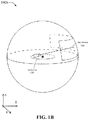
- FIGS. 1A and 1B respectively show diagrams 100 a and 100 b of a dome framework that illustrate a view of an XYZ-space with an example of a virtual space and structure in accordance with aspects of the present disclosure.
- the diagram 100 a shows a virtual dome sphere 110 , a center point 135 associated with a user, a center area 130 about the center point 135 , a virtual camera 120 that is directed into a gaze area 115 on the virtual dome sphere 110 , and a dome radius 125 .
- the dome framework show in the diagram 100 a may be implemented using a dome device (e.g., a HMD, one or more 3D cameras, one or more 3D displays, or projection device).
- a dome device e.g., a HMD, one or more 3D cameras, one or more 3D displays, or projection device.
- the diagram 100 b in FIG. 1B shows a view direction 140 from the user to the gaze area 115 on the virtual done sphere 110 .
- the dome radius 125 may be adjusted and the virtual dome sphere 110 may be resized.
- the virtual camera 120 can be considered to be a user's eye sight.
- a first person game e.g., a shooting game
- the HMD is capable of providing augmented reality and therefore display 3D images including 3D images of screens.
- the screen contents may be mapped using a UV mapping technique.
- FIGS. 2A and 2B respectively show diagrams 200 a and 200 b of a dome framework that illustrate a view of a dome sphere space structure with an example of the dome sphere radius and initial screen position in accordance with aspects of the present disclosure.
- the diagram 200 a shows a screen 210 being projected, displayed, or imaged onto the gaze area 115 .
- the screen 210 may be projected by a dome device that implements the dome framework.
- the screen 210 being projected or imaged may be an initial or default screen 210 and may be on an initial virtual dome sphere 110 as illustrated in the diagram 200 b in FIG. 2B where the virtual dome sphere 110 is shown in solid lines to indicate a base, main, or primary sphere in the dome framework. Additional screens 210 may be added after the initial or default screen 210 .
- a size of the screen 210 (e.g., an aspect ratio) may be determined before projecting or imaging the screen 210 .
- diagrams 200 a and 200 b show the virtual camera 120 in the center area 130 , there may be instances in which the virtual camera 120 may be implemented outside of the virtual dome sphere 110 and still be configured to project the screen 120 as described.
- FIGS. 3A and 3B respectively show diagrams 300 a and 300 b of a dome framework that illustrate a field of view of a user immersed in the augmented/virtual reality screen as displayed to the user within a gazing area in accordance with aspects of the present disclosure.
- the diagram 300 a shows the gazing area 115 having multiple screens 210 projected within the gaze area 115 and arranged in some way.
- the screens 210 may be arranged horizontally, vertically, in a matrix, or in some other fashion within the grazing area 115 .
- the screens 210 have been shown to be of approximately the same size, there may be instances in which the screens 210 are of two or more sizes as described in further detail below.
- the diagram 300 b shows that the user can select (e.g., via some control mechanisms such as keyboards, wired or wireless controllers, motion sensors, voice activation, gestures, etc.) one or more screens 210 for focusing because the digital assets being provided by those screens are of more relevance to the user at the particular time of the selection.
- focus screens 310 a and 310 b are selected and may be brought closer to the user for convenience.
- bringing a focus screen 310 closer to the user may mean that the screen is projected in such a way that appears closer to the user than the other screens.
- the focus screens can be moved around or placed somewhere where it is of easier use to the user.
- FIG. 4 shows a diagram 400 of a dome framework that illustrates an example of screens positioned in different sphere layer structures (or simply layers) in accordance with aspects of the present disclosure.
- the dome framework that is implemented includes two layers (or meshes/rings), a dome layer 1 410 a and a dome layer 2 410 b .
- Each of these layers can have one or more screens projected onto it by the virtual camera 120 .
- multiple screens 420 a are projected onto the dome layer 1 420 a , which is closer to the user, and multiple screens 420 are projected onto the dome layer 2 410 b , which is farther away from the user.
- the number of layers and the number of screens in each layer can vary and may depend on the number of digital assets, the importance or relevance of those digital assets, the type of collaboration with other users, and/or on other criteria.
- FIGS. 5A and 5B respectively show diagrams 500 a and 500 b of a dome framework that illustrate a top view in which a number of screens are positioned in different layers in accordance with aspects of the present disclosure.
- the diagram 500 a shows concentric dome layers 510 a (dome layer 1), 510 b (dome layer 2), and 510 c (dome layer 3) on a ZX plane.
- the different layers in this arrangement are used to surround the user within a sphere space (e.g., a user oriented interface).
- the spacing between dome layers is shown as being similar between any two adjacent dome layers, it may not be the case and the spacing between adjacent dome layers may vary within the dome framework implementation.
- the diagram 500 b further shows in the ZX plane the gaze area 115 within which screens can be projected onto each of the dome layers.
- a single screen 520 a is projected or imaged onto the dome layer 1 510 a
- a single screen 520 is projected onto the dome layer 2 510 b
- two screens 520 c are projected onto the dome layer 3 510 c.
- the order of the layers may be dynamically varied and the screens adjusted accordingly. For example, a layer may be moved forward closer to the user or a layer may be moved backward away from the user.
- the screens associated with the layers may move with the layers when the layers are moved forward or backward.
- FIG. 6A shows a diagram 600 a of a dome framework that illustrates a top view (on a ZX plane) in which a number of screens face different directions and are aimed toward the center or virtual camera in accordance with aspects of the present disclosure.
- the dome 110 does not have multiple layers and multiple screens 210 are projected onto the dome 110 (e.g., a single main or primary layer).
- Each of the screens 210 e.g., virtual screens
- there are three (3) screens 210 a center screen faces the user directly, while the two screens to the sides of the center screen face the user at an angle.
- FIG. 6B shows a diagram 600 b of a dome framework that illustrates a top view (on a ZX plane) in which a focus screen is brought toward a user in the spatial manner in accordance with aspects of the present disclosure.
- the center screen is selected as a focus screen 310 (see e.g., in FIG. 3B ) and is moved forward towards the user along the view direction 140 (e.g., is projected such that it appears closer to the user than other screens).
- the focus screen 310 As the focus screen 310 is moved forward, it can be enlarged or otherwise right-sized for better consumption (e.g., view) by the user.
- FIG. 7A shows a diagram 700 a of a dome framework that illustrates a view of a screen window boundary area for customizable functions interface in accordance with aspects of the present disclosure.
- a screen 210 may have a screen border 710 that surrounds all (as shown) or part of the screen 210 .
- the screen border 710 may be used to display or enable custom functions, which may be associated with the display assets provided through the screen 210 .
- FIG. 7B shows a diagram 700 b of a dome framework that illustrates a view of a screen window expansion layout/area for additional screens build in accordance with aspects of the present disclosure.
- the screen 210 may be expanded by increasing its area. This increase can take the form of adding one or more screens 720 , which may or may not be in use. It is possible to add screens 720 to the left, right, top, bottom, or some combination (e.g., left-top, right-bottom) of the screen 210 .
- the screens 720 being added to increase the area or size of the screen 120 need not be of the same size as the screen 120 and/or need not be all of the same size.
- FIG. 8A shows a diagram 800 a of a dome framework that illustrates an XZ-plane view of a vision region when viewed from an Y-direction offset from a center position in accordance with aspects of the present disclosure.
- the virtual camera is offset from the center and the screen 210 may be directed to face the virtual camera along the view direction 140 .
- the screen axis 610 of the screen 210 in this example may be tilted such that the screen 210 faces directly in the opposite direction to the view direction 140 (as illustrated by equal angles ⁇ to either side of the view direction 140 ).
- FIG. 8B shows a diagram 800 b of a dome framework that illustrates an ZX-plane view of a vision region when viewed from a Y-direction offset from a center position in accordance with aspects of the present disclosure.
- the screen 210 faces in the direction of the virtual camera 120 along the view direction 140 (as illustrated by equal angles ⁇ to either side of the view direction 140 ). Therefore, the diagrams 800 a and 800 b show different angles of where the virtual camera 120 stands and the screen angles.
- FIG. 9A shows diagrams 900 a and 900 b of a dome framework that illustrate a placement angle of the screen in accordance with aspects of the present disclosure.
- the screen 210 is positioned perfectly vertical, while in the diagram 900 b the screen 210 is slightly slanted (angle ⁇ ) from the vertical position and so the view direction 140 is also slanted upwards by the same angle so that the view direction 140 is normal to the surface of the screen 210 .
- angle ⁇ the view direction 140 is also slanted upwards by the same angle so that the view direction 140 is normal to the surface of the screen 210 .
- FIG. 9B shows a diagram 900 c of a dome framework that illustrates an orthogonal coordinate system on a three-dimensional space in accordance with aspects of the present disclosure.
- the user can rotate his or her view direction and can therefore cover a significant portion of the virtual environment provided by the dome framework.
- Rotation around the front-to-back axis is called roll.
- Rotation around the side-to-side axis is called pitch.
- Rotation around the vertical axis is called yaw.
- the head of a user that wears an HMD may be assumed to be in the center area (see e.g., the center area 130 , the center point 135 in the diagram 100 a in FIG. 1A ).
- FIGS. 10A and 10B respectively show diagrams 1000 a and 1000 b of a dome framework that illustrate a layout relationship between screens layout and split screens in accordance with aspects of the present disclosure.
- the diagram 1000 a shows how a screen 210 projected in a dome framework can be split into multiple, smaller screens.
- the screen 210 is split into at least two smaller screens 1010 a and 1010 b , and possibly more. Although up to four (4) smaller screens are shown, the screen 210 can be split into two or more screens.
- the diagram 1000 b shows different configurations in which screens can be organized.
- Each of the configurations 1020 a , 1020 b , 1020 c , and 1020 d includes multiple screens of different sizes and in different positional arrangements. Each of these configurations may also be an example of splitting a larger screen into multiple smaller screens of different sizes and different positional arrangements. It is to be understood that the configurations 1020 a , 1020 b , 1020 c , and 1020 d are provided by way of illustration and not of limitation and other configurations may also be implemented.
- FIGS. 11A and 11B respectively show diagrams 1100 a and 1100 b of a dome framework that illustrate rotational directions of a screen in accordance with aspects of the present disclosure.
- a screen 210 can be in a landscape or horizontal configuration (left) and can rotate about a screen axis 610 , or the screen 210 can be in a portrait or vertical configuration (right) and can rotate about the screen axis 610 .
- a screen 210 can be in a landscape or horizontal configuration and can rotate front-to-back or back-to-front about a screen axis 610 (left), or the screen 210 can be in the landscape or horizontal configuration and can rotate top-to-bottom or bottom-to-top about the screen axis 610 (right).
- the screen 210 it is possible for the screen 210 to be in a portrait/vertical configuration and also be able to rotate front-to-back or back-to-front or rotate top-to-bottom or bottom-to-top about a screen axis 610 .
- FIG. 12 is a flowchart that illustrates an example of a method 1200 for building a dome framework in accordance with aspects of the present disclosure.
- the method 1200 may include at 1210 , determining a device format.
- a device format may refer to whether the device is an HMD, PC, tablet, mobile device, custom monitors etc. Based on many device formats, the contents might be displayed in a diffident layout.
- the HMD might have a sphere screen display, any other flat viewing device will have a XY screen layout to display the screens.
- the method 1200 may determine whether a sphere (e.g., the virtual dome sphere 110 ) exists or has been configured.
- the method 1200 proceeds to 1230 to generate a sphere. If a sphere does exist or has been configured, the method 1200 proceeds to 1240 to determine a gaze area or field of view area (e.g., the gaze area 115 ).
- the method 1200 may set a vertex point and generate a default screen based on the position of the vertex point.
- the method 1200 may generate a log info and build a list of contents (e.g., the data assets that are needed or are being provided).
- the method 1200 may determine the contents amount.
- the method 1200 may generate additional screens based on the contents amount.
- the method 1200 may render the contents on the screens (e.g., one or more screens 210 ).
- FIG. 13 is a flowchart that illustrates an example of a method 1300 for building layers (see e.g., dome layers in the diagrams 400 , 500 a , and 500 b in FIGS. 4, 5A, and 5B ) in a dome framework in accordance with aspects of the present disclosure.
- the method 1300 may include, at 1310 , determining the existing spheres amount. That is, a determination is being made as to how many spheres or layer are already configured to see if more are needed to display extra screens.
- the method 1300 may include determining the features of the existing spheres environment (e.g., radius, screen count, layout, configuration, etc.).
- the method 1300 may include generating a new sphere (e.g., a layer) with a greater radius than any existing sphere.
- the method 1300 may include allow the sphere to dynamically resize based on the context.
- the method 1300 may include determining a gaze area or field of view (e.g., the gaze area 115 ) for the new sphere.
- the method 1300 may include determining the input content for the new sphere.
- the method 1300 may include determining an aspect ratio for a screen on the new sphere.
- the method 1300 may include generating the screen (e.g., projecting a screen 210 onto the new sphere or layer), and at 1390 may include rendering the content to be displayed on the screen.
- FIG. 14 is a flowchart that illustrates an example of a method 1400 for building screens and additions in a dome framework in accordance with aspects of the present disclosure.
- the method 1400 may include, at 1410 , determining a display type (e.g., HMD, PC, tablet, mobile devices, custom screens, etc.).
- the method 1400 may include determining contents amount and type (e.g., amount and type of content in digital assets).
- the method 1400 may include establishing a minimum/maximum aspect ratio of each screen based on the display type.
- the method 1400 may include rendering the contents on the screens.
- the method 1400 may include enabling and allowing the user to resize the screens without violating the minimum/maximum aspect ratio.
- the method 1400 may include enabling and allowing the user to re-position one or more screens or move the rendered contents into a different set of screens.
- the method 1400 may include enabling and allowing a user to select content and move predefined layers.
- the method 1400 may include other aspects in which, based on the content and/or the minimum/maximum aspect ratio, additional screens may be added to a main screen to expand the main screen (see e.g., the diagram 700 b in FIG. 7B ).
- FIG. 15 is a flowchart that illustrates an example of a method 1500 for determining a focus gaze area in accordance with aspects of the present disclosure.
- the method 1500 may include, at 1510 , determining a view position.
- the method 1500 may include determining a gaze area or field of view area (e.g., the gaze area 115 ).
- the method 1500 may include determining main screens and/or sub-screens (see e.g., the diagram 1000 a in FIG. 10A ).
- the method 1500 may include activating a Q system focus cell module (see e.g., FIG. 16 ).
- the focus cell module may be used by the Q system for higher resolution and detail oriented attributes to be available to the user for, for example, professional production ready contents.
- the method 1500 may include providing features of the focus cell module functions.
- the method 1500 may include setting the attributes of the focus cell to the main screens.
- the method 1500 may include setting the focal point to the main screens.
- aspects of the method 1500 may be used to determine where to place the gaze area, what the gaze area is to include (e.g., number of screens and/or sub-screens), and various attributes or configurations of the gaze area.
- FIG. 16 shows block-level diagram of a focus cell processing module 1600 (e.g., the Q system focus cell module described above in connection with the method 1500 ) in accordance with aspects of the present disclosure.
- the module 1600 may include various units or components.
- the module 1600 may include a content acquisition unit 1610 , a content information analysis unit 1620 , a content resolution adjustment unit 1630 , a screen position determination unit 1640 , a render content generation unit 1650 , a render area specification unit 1660 , and a reproduction unit 1670 .
- the module 1600 may be used in connection with at least some aspects of the methods 1200 , 1300 , 1400 , and 1500 . That is, the module 1600 may be used in connection with at least some aspects of building a dome framework, building layers in a dome framework, building screens and additions in a dome framework, and/or determining a focus gaze area.
- FIGS. 17A and 17B respectively show flowcharts that illustrate examples of a method 1700 a for a head mounted display (HMD) and a method 1700 b for a monitor or display device, both of which are for detecting the three-dimensional viewing platform (e.g., Q system platform) in accordance with aspects of the present disclosure.
- HMD head mounted display
- Q system platform three-dimensional viewing platform
- the method 1700 a may include, at 1705 , detecting sensor motion in the HMD.
- the method 1700 a may include detecting a center axis.
- the method 1700 a may include detecting a space.
- the method 1700 a may include detecting a gaze.
- the method 1700 a may include detecting a Q system focus cell point. On a default scene, this point can be the center default screen, and on an ongoing project, this can be the latest screen the user was viewing.
- the method 1700 b may include, at 1730 , detecting a device type.
- the method 1700 b may include detecting a display setting.
- the method 1700 b may include detecting a layout.
- the method 1700 b may include detecting a monitor count.
- the method 1700 b may include detecting a Q system focus cell point.
- the focus point can be the application window (e.g., the Q application window).
- FIGS. 18A and 18B respectively show diagrams 1800 a and 1800 b of a behavior sync that illustrate examples of detecting pattern layout in accordance with aspects of the present disclosure.
- the diagram 1800 a shows a screen detecting layer 1810 with a screen detecting pattern 1820 a that includes a grid of black and white squares.
- the diagram 1800 b shows the screen detecting layer 1810 with a screen detecting pattern 1820 b that includes a grid of black and white triangles.
- a part of the behavior sync process to synchronize the behavior, each users' movements and interaction will be read as a pattern by using SVG (Scalable Vector Graphics) data format and this data will be using a GPU processor to sync with the other users' display.
- SVG Scalable Vector Graphics
- FIG. 19A shows a diagram 1900 a of a behavior sync that illustrates an example of users screen layers and viewing direction in accordance with aspects of the present disclosure.
- a first user (user 1) has a view in the view direction 140 of a content screen 1920 at the virtual camera 120 and within the gaze area 115 .
- a second user can also view the same content screen 1920 and the first user (user 1) can view the second user's indicator interaction through a second user screen (user 2 screen) 1910 a .
- FIG. 19B shows a diagram 1900 b that is similar to the diagram 1900 a .
- the third user is at the position of the virtual camera 120 and the first user can also view the same content screen 1920 and the third user (user 3) can view the first user's indicator interaction through a first user screen (user 1 screen) 1910 d .
- FIG. 19C shows a diagram of a behavior sync that illustrates an example of a screen content management table 1900 c in accordance with aspects of the present disclosure.
- the various screens in the diagram 1900 a or the diagram 1900 b may be tracked by screen identifier (ID) on a first column, with other information also tracked including at least a content ID column, a project ID column, an aspect ratio of the screens column, and a contents status column.
- ID screen identifier
- FIG. 20 is a flowchart that illustrates an example of a method 2000 for implementing a user interaction in accordance with aspects of the present disclosure.
- a method 2000 for implementing a user interaction in accordance with aspects of the present disclosure.
- an interaction between a User 1 and a User 2 is shown in connection with a project collaboration, but such interaction may be expanding to other users as well.
- the method 2000 may include accessing data associated with a project instance.
- the method 2000 may include analyzing data associated with project condition to determine the screen and position indicator.
- the method 200 may include modifying sync data to locate indicator on screen at the determined position.
- the method 2000 may include sending sync data to one or more clients over a network.
- the method 2000 may include receiving from User 1 the sync data over the network.
- the method 2000 may include presenting an indicator on a screen layer at the determined position for the user.
- the method 2000 may include receiving user interaction.
- the method 2000 may include providing data associated with the user interaction to the project instance.
- the method 2000 may include receiving from User 2 the data associated with the user interaction.
- the method 2000 may include presenting an indicator on the screen layer at the determined position for the user.
- the method 2000 may include updating sync data based on the data associated with the user interaction.
- FIG. 21A is a flowchart that illustrates an example of a method 2100 a for recording a user indicator in accordance with aspects of the present disclosure.
- a user indicator is like a mouse pointer or some other indicator of the activities of a user.
- the method 2100 a may include, at 2105 , receiving input to initiate project capture process.
- the method 2100 a may include associating a work logic identifier with a screen layer.
- a work logic may refer to a project workflow and may include pre-defined both tools and interaction.
- a work logic identifier may refer to an number or value that identifies a particular project workflow.
- the method 2100 a may include initiating a screen layer capture.
- the method 2100 a may include storing initial state parameters values (e.g., the user indicator input, movement, velocity values).
- the method 2100 a may include storing state parameter values at defined intervals.
- the method 2100 a may include receive input (or some indication) to end the project capture process.
- the method 2100 a may include ending the project capture process.
- FIG. 21B is a flowchart that illustrates an example of a method 2100 b for building a scalable vector graphics (SVG) pattern in accordance with aspects of the present disclosure.
- the method 2100 b may include, at 2150 , determining the work logic.
- the method 2100 b may include determining a screen ID.
- the method 2100 b may include determining a screen layer data.
- the method 2100 b may include analyzing the interaction data of an indicator (e.g., user indicator).
- the method 2100 b may include generating an SVG pattern.
- the method 2100 b may include sending the indicator data to a host server.
- the method 2100 b may include reading a pattern of an indicator and generating SVG to synchronize the behavior of a user workflow and create patterns from the user movement to improve the efficiency of future use of similar workflow.
- the Q system can predict the movement and suggest the user or do the work for the user when the user is not available to work in the same or similar project.
- FIG. 22A is a flowchart that illustrates an example of a method 2200 a for determining synchronization between users in accordance with aspects of the present disclosure.
- the method 2200 a may include, at 2205 , receiving user input data.
- the method 2200 a may include determining or identifying a screen layer.
- the method 2200 a may include calculating an indicator position and velocity (e.g., the speed and the input of the indicator).
- the method 2200 a may include calculating or identifying tools to be displayed from user information.
- the method 2200 a may determine if all the data has been calculated. If all the data has not been calculated, the method 2200 a may return to 2215 . If all the data has been calculated, the method 2200 a may proceed to 2230 where input data is rendered on the screen layer.
- FIG. 22B is a flowchart that illustrates an example of a method 2200 b for determining work logic in accordance with aspects of the present disclosure.
- the method 2200 b may include, at 2240 , initiating a work logic identifier.
- work logic may refer to a project workflow or a project base setup for a user. If the project is for making a TV car commercial, for example, there are sudden tool sets available to be used for this purpose. The same may happen with any other projects where there is always a tool or set of tools to be used to build the production workflow.
- the method 2200 b may include determining a project content and type.
- the method 2200 b may include determining presets and tools according to the project content and type (e.g., 3D animation, car commercials, YouTube content build, video editing, music creation).
- the method 2200 b may include establishing rules and patterns (e.g. user-associated patterns).
- the method 2200 b may include setting the work logic identifier to the project instance.
- FIG. 22C is a flowchart that illustrates an example of a method 2200 c for building screen layers in accordance with aspects of the present disclosure.
- the method 2200 c may include, at 2270 , receiving user input data.
- the method 2200 c may include initiating or configuring a screen layer associated with the user input data.
- the method 2200 c may include determining a screen content.
- the method 2200 c may include establishing a cell pattern type (see e.g., FIGS. 18A and 18B ).
- the method 2200 c may include emulating the screen content.
- emulating the screen content can be the process used on each of the user's content screen.
- the method 2200 c may include presenting the indicator on the screen layer.
- FIG. 23 show a block diagram that illustrates an example of a network system 2300 in accordance with aspects of the present disclosure.
- the network system 2300 may be used to implement aspects of the Q system and enable collaboration or interaction between users of the Q system as described above.
- the network system 2300 includes a host system 2310 .
- the host system 2310 may have an application server that supports the smart stream and behavior sync functionalities described herein.
- the host system 2310 may also include a real-time communications (RTC) server that supports chat/voice functionality.
- RTC real-time communications
- the host system 2310 may also include a web server that supports video streaming and license/key/token functionalities.
- the host system 2310 may include a repository and a database.
- the network system 2300 may also have a first client computing system 2320 b (client computing system 1 for a first user) and a second client computing system 2320 a (client computing system 2 for a second user).
- the first client computing system 2320 b may include computing resources, an application data store, a Q system browsing application that supports dome framework and focus gaze cell functionalities, and a Q system streaming application that supports behavior sync and smart stream.
- the second client computing system 2320 a may include computing resources, an application data store, a Q system browsing application that supports dome framework, focus gaze cell, and browse application (APP) functionalities.
- APP browse application
- the host system 2310 , the first client computing system 2320 b , and/or the second client computing system 2320 a may communicate through a network 2330 that may be implemented wirelessly, wired, or by a combination of both.
- FIG. 24 shows a block diagram that illustrates an example of a customizable, adaptable, multiuser network system 2400 in accordance with aspects of the present disclosure.
- the network system 2400 may be used to implement aspects of the Q system and enable collaboration or interaction between users of the Q system as described above.
- the network system 2400 may include a media service system 2410 , a first client computing system 2420 a (client computing system 1 A for a first user), a second client computing system 2420 b (client computing system 1 B for a second user), and a third client computing system 2420 c (client computing system 2 for a third user).
- the media service system 2410 may have an RTC server that supports chat/voice functionality.
- the media service system 2410 may also include a web server that supports video streaming and license/key/token functionalities.
- the media service system 2410 may include a repository and a database.
- Both of the first client computing system 2420 a and the second client computing system 2420 b may include computing resources, an application data store, a Q system browsing application that supports dome framework and focus gaze cell functionalities, and a Q system streaming application that supports behavior sync and smart stream.
- the third client computing system 2420 c may include computing resources, an application data store, a Q system browsing application that supports dome framework, focus gaze cell, and browse APP functionalities.
- the media service system 2410 , the first client computing system 2420 a , the second client computing system 2420 b , and/or the third client computing system 2420 c may communicate through a network 2430 that may be implemented wirelessly, wired, or by a combination of both.
- FIG. 25 shows a block diagram that illustrates an example of a customizable client-to-client network system 2500 in accordance with aspects of the present disclosure.
- the network system 2500 may be used to implement aspects of the Q system and enable direct collaboration or interaction between users of the Q system as described above.
- the network system 2500 may include a first client computing system 2520 a (client computing system 1 A for a first user) and a second client computing system 2520 b (client computing system 1 B for a second user). Both of the first client computing system 2520 a and the second client computing system 2520 b may include computing resources, an application data store, a Q system browsing application that supports dome framework and focus gaze cell functionalities, and a Q system streaming application that supports behavior sync and smart stream.
- the first client computing system 2520 a and the second client computing system 2520 b may communicate through a network 2530 that may be implemented wirelessly, wired, or by a combination of both.
- FIG. 26A is a flowchart that illustrates an example of a method 2600 a for initiating an application in a three-dimensional viewing platform (e.g., Q system) in accordance with aspects of the present disclosure.
- the method 2600 a may include, at 2605 , initiating an application (e.g., a Q application, Q browsing application, Q streaming application) associated with a project instance.
- the method 2600 a may include loading the application.
- the method 2600 a may include initiating a work logic identifier associated with the project instance.
- the method 2600 a may include determining a project state based on the work logic identifier.
- the method 2600 a may include receiving project state data associated with the project instance.
- the method 2600 a may include generating the project instance within the application.
- the method 2600 a may include providing access to a user to the project instance.
- FIG. 26B shows a flowchart that illustrates an example of a method 2600 b for inviting an external user to join an application in a three-dimensional viewing platform (e.g., Q system) in accordance with aspects of the present disclosure.
- the method 2600 b may include, at 2650 , receiving a request to join a project of an application from an external user.
- the method 2600 b may include verifying the credential of the external user requesting to join the project/application (e.g., verifying whether the user is authorized to join).
- the method 2600 b may include determining a state of the project.
- the method 2600 b may include sending project data associated with the project instance to a host system or a media service system (see e.g., FIGS. 23 and 24 ).
- the method 2600 b may include providing access to the user to the project instance.
- the method 2600 b may include providing access to the user to the work logic data.
- FIG. 27A is a block diagram that illustrates an example of a smart stream module 2700 a in accordance with aspects of the present disclosure.
- the smart stream module 2700 a may be used to implement, perform, enable, control, and/or support features or functionality associated with the smart stream component of the Q system.
- the smart stream module 2700 a may include hardware and/or software organized in multiple units, each of which can perform a subset of the operations of the smart stream module 2700 a .
- the smart stream module 2700 a may include a content acquisition unit 27102 , a content data unit 2704 , a content playback unit 2706 , a screen ID unit 2708 , a UV mapping unit 2710 , a content recording unit 2712 , a work logic data unit 2714 , a sync event unit 2716 , a content render unit 2718 , a content reproduction unit 2720 , and a screen layer unit 2722 .
- These units may be used in connection with one or more features, functions, operations, and/or steps described above in connection with the Q system, including some of the relevant methods described above, and more particularly, in connection with the smart stream component of the Q system.
- FIG. 27B shows a block diagram that illustrates an example of a behavior sync module in accordance with aspects of the present disclosure.
- the behavior sync module 2700 b may be used to implement, perform, enable, control, and/or support features or functionality associated with the behavior sync component of the Q system.
- the behavior sync module 2700 b may include hardware and/or software organized in multiple units, each of which can perform a subset of the operations of the behavior sync module 2700 b .
- the behavior sync module 2700 b may include a content data unit 2730 , an indicator analysis unit 2732 , a screen ID unit 2734 , a project analysis unit 2736 , an indicator data unit 2738 , a sync event unit 2740 , an SVG unit 2742 , a machine learning unit 2744 , a screen layer unit 2746 , and a work logic data unit 2748 .
- These units may be used in connection with one or more features, functions, operations, and/or steps described above in connection with the Q system, including some of the relevant methods described above, and more particularly, in connection with the behavior sync component of the Q system.
- FIG. 28A shows a diagram 2800 a that illustrates for a smart stream an example of a UV coordinate number system in accordance with aspects of the present disclosure.
- the diagram 2800 a shows a stream texture UV mapping process with assigned ID to a sequence (e.g., “[ID]”) and identified a linear UV order.
- the +U scale is shown horizontally and the +V scale is shown vertically.
- FIG. 28B shows a diagram 2800 b that illustrates for a smart stream an example of a UV map layout in accordance with aspects of the present disclosure.
- a sequence of maps with corresponding IDs are shown, where the U and V scales have been normalized to be in the range 0-1.
- FIG. 29 shows diagrams 2900 a and 2900 b that illustrate for a smart stream examples of a UV map identifier (ID) system in accordance with aspects of the present disclosure.
- the diagrams 2900 a and 2900 b show tables in which UV mapping information is included for handling the UV mapping.
- the table includes at least a content column, a type column, a UV ID column, a sequence start number column, a sequence end number column, and a file name column.
- the table includes at least a screen ID column, a format column, a UV ID column, a UV coordination (COORD) column, a sequence ID column, and an aspect ratio column.
- COORD UV coordination
- FIG. 30 is a block diagram of a computing device system 3000 for implementing the functionality of a three-dimensional viewing platform (e.g., Q system) in accordance with aspects of the present disclosure.
- the computing device system 3000 may be used to implement any one or all of the aspects of the Q system (e.g., dome framework, focus gaze cell, smart stream, and behavior sync). In some instances, more than one computing device system 300 may be used when implementing the Q system or portions thereof.
- the computing device system 3000 may include one or more of a memory 3005 , a storage 3010 , a user input device 3015 , an audio processor 3020 , a network interface 3025 to connect to a network 3030 , a central processing unit (CPU) 3035 , a graphics card 3040 having a graphics processing unit (GPU) 3040 and a graphics memory 3050 , or a display 3060 .
- the display 3060 may be used to display one or more screens 210 and may be configured to provide depth or layering capabilities (e.g., 3D display capabilities) when displaying the one or more screens 210 .
- These elements, components, or devices of the computing device system 3000 may communicate through one or more buses as shown by the arrows.
- FIG. 31 shows a block diagram of a head mounted display (HMD) system 3100 used in connection with a three-dimensional viewing platform (e.g., the Q system) in accordance with aspects of the present disclosure.
- the HMD system 3100 may be used to implement any one or all of the user aspects associated the Q system.
- the HMD system may include one or more of a memory/storage 3105 , a gaze tracking module(s) 3110 , an application engine 3115 , input devices 3120 , audio capabilities 3125 , a network interface 3135 to connect to a network 3140 , one or more processors 3145 (e.g., CPU, GPU), sensor(s) 3150 , motion sensor(s) 3155 , orientation sensor(s) 3160 , position sensor(s) 3165 , optical sensor(s) 3170 , or an eye-tracking system 3175 .
- processors 3145 e.g., CPU, GPU
- sensor(s) 3150 e.g., motion sensor(s) 3155 , orientation sensor(s) 3160 , position sensor(s) 3165 , optical sensor(s) 3170 , or an eye-tracking system 3175 .
- FIG. 32 is a flowchart that illustrates an example of a method 3200 for manipulating digital assets on a three-dimensional viewing platform in accordance with aspects of the present disclosure. Aspects of the method 3200 may be performed by one or more of the computing device system 3000 , one or more of the HMD system 3100 , or a combination thereof.
- the method 3200 may include configuring at least one dome layer as part of a dome framework having a spherical virtual environment that surrounds a user.
- the method 3200 may include virtually displaying, within a gaze area for the user, at least one screen in the at least one dome layer, wherein one or more digital assets are provided to the user through the at least one screen.
- the method 3200 may include enabling the user to interact with the one or more digital assets on the at least one screen.
- the graze area is on a top hemisphere of the spherical virtual environment.
- the user is positioned near or at a center point of the spherical virtual environment.
- virtually displaying at least one screen within the gaze area includes virtually displaying multiple screens, where the multiple screens are arranged horizontally, vertically, in a matrix, or in a random fashion.
- the method 3200 may further include selecting one or more screens from the multiple screens for focused viewing by the user, where the selected one or more screens for focused viewing are virtually displayed to appear closer to the user than the unselected screens.
- the method 3200 may further include adjusting the selected one or more screens for focused viewing in size, position, viewing direction, or a combination thereof.
- configuring at least one dome layer includes configuring multiple concentric dome layers as part of the dome framework, and virtually displaying at least one screen within the gaze area includes virtually displaying at least one screen in each of the dome layers.
- the dome layers may include an initial or default dome layers and one or more additional dome layers, the initial dome layer having a radius corresponding to the radius of the spherical virtual environment that surrounds the user, and the one or more additional dome layers each having a radius that is greater than the radius of the initial dome layer.
- the one or more digital assets may be provided to the user through the at least one screen in each of the dome layers.
- each of the at least one screen has a screen axis associated with a direction the screen faces, and the direction is configured to face the user.
- the at least one screen includes a screen border within which to display or enable custom functions.
- the method 3200 may further include adjusting a size of the at least one screen by adding one or more screens to form a larger screen.
- the user is free to rotate view direction within the spherical virtual environment and within the same gaze area or in a different gaze area, the rotation of the user may include a change in roll, a change in pitch, a change in yaw, or a combination thereof.
- virtually displaying the at least one screen within a gaze area for the user further includes rotating the at least one screen about a screen axis, the rotation including a clockwise rotation, a counterclockwise rotation, a front-to-back rotation, a back-to-front rotation, a top-to-bottom rotation, a bottom-to-top rotation, a partial one of any of these rotations, or a combination of any of these rotations.
- virtually displaying the at least one screen within a gaze area for the user further includes rotating the at least one screen between a landscape/horizontal position and a portrait/vertical position.
- the method 3200 may further include interacting with at least one other user through the at least one screen.
- Interacting with at least one other user may include viewing through the at least one screen a screen of the at least one other user.
- Interacting with the at least one other user may include viewing through the at least one screen a same content screen that the at least one other user is also viewing.
- Interacting with the at least one other user may include working on a same project instance through the at least one screen.
- Interacting with the at least one other user may include verifying the at least one other user and providing access to a project instance when the at least one other user is verified.
- Interacting with the at least one other user may include identifying, for a project instance, a work logic identifier that indicates a particular project workflow including pre-defined tools and user interactions.
- Interacting with the at least one other user may include analyzing data for the user and the at least one other user and generating patterns based on the analyzed data for future projects or to review a current project.
- Interacting with the at least one other user may include having a dome layer for each user, monitoring an indicator movement for each of the users through each user input and output patterns, and setting up the types of functions and schemes supported in each of the layers based on the input and output pattern of the respective user.
- Interacting with the at least one other user may include reading a pattern of user indicators and generating patterns from the movement in the user indicators to improve the efficiency of future use of the same or similar project workflow.
- the method 3200 may further include, for the one or more digital assets, performing a stream texture UV mapping process and assigning a corresponding identifier (ID) to each UV map in the process.
- ID a corresponding identifier
- the present disclosure describes aspects of a system for manipulating digital assets on a three-dimensional viewing platform, where the system includes a memory configured to store instructions, and one or more processors configured to execute the instructions to configure at least one dome layer as part of a dome framework having a spherical virtual environment that surrounds a user, to virtually display, within a gaze area for the user, at least one screen in the at least one dome layer, wherein one or more digital assets are provided to the user through the at least one screen, and to enable the user to interact with the one or more digital assets on the at least one screen.
Landscapes
- Engineering & Computer Science (AREA)
- Theoretical Computer Science (AREA)
- Physics & Mathematics (AREA)
- General Engineering & Computer Science (AREA)
- General Physics & Mathematics (AREA)
- Human Computer Interaction (AREA)
- Computer Graphics (AREA)
- Computer Hardware Design (AREA)
- Multimedia (AREA)
- Architecture (AREA)
- Computer Vision & Pattern Recognition (AREA)
- Software Systems (AREA)
- Computing Systems (AREA)
- Geometry (AREA)
- User Interface Of Digital Computer (AREA)
Abstract
Description
Claims (26)
Priority Applications (1)
| Application Number | Priority Date | Filing Date | Title |
|---|---|---|---|
| US16/523,773 US10861249B2 (en) | 2018-07-27 | 2019-07-26 | Methods and system for manipulating digital assets on a three-dimensional viewing platform |
Applications Claiming Priority (2)
| Application Number | Priority Date | Filing Date | Title |
|---|---|---|---|
| US201862703991P | 2018-07-27 | 2018-07-27 | |
| US16/523,773 US10861249B2 (en) | 2018-07-27 | 2019-07-26 | Methods and system for manipulating digital assets on a three-dimensional viewing platform |
Publications (2)
| Publication Number | Publication Date |
|---|---|
| US20200035040A1 US20200035040A1 (en) | 2020-01-30 |
| US10861249B2 true US10861249B2 (en) | 2020-12-08 |
Family
ID=69178571
Family Applications (1)
| Application Number | Title | Priority Date | Filing Date |
|---|---|---|---|
| US16/523,773 Expired - Fee Related US10861249B2 (en) | 2018-07-27 | 2019-07-26 | Methods and system for manipulating digital assets on a three-dimensional viewing platform |
Country Status (1)
| Country | Link |
|---|---|
| US (1) | US10861249B2 (en) |
Cited By (1)
| Publication number | Priority date | Publication date | Assignee | Title |
|---|---|---|---|---|
| US20230014520A1 (en) * | 2021-07-19 | 2023-01-19 | Advanced Micro Devices, Inc. | Content feedback based on region of view |
Families Citing this family (6)
| Publication number | Priority date | Publication date | Assignee | Title |
|---|---|---|---|---|
| CN110324601A (en) * | 2018-03-27 | 2019-10-11 | 京东方科技集团股份有限公司 | Rendering method, computer product and display device |
| CN109254660B (en) * | 2018-08-31 | 2020-11-17 | 歌尔光学科技有限公司 | Content display method, device and equipment |
| US11206365B2 (en) * | 2020-01-13 | 2021-12-21 | Charter Communications Operating, Llc | Method and apparatus for overlaying themed imagery onto real-world objects in a head-mounted display device |
| EP4237902A4 (en) * | 2020-10-29 | 2024-12-18 | Innovative Transducer Implementation LLC | SYSTEM AND METHOD FOR ARRANGEMENTS OF VISUAL INFORMATION IN USER-CONFIGURABLE FORMAT |
| CN118266206A (en) * | 2021-11-26 | 2024-06-28 | 株式会社半导体能源研究所 | Display device |
| US11914858B1 (en) * | 2022-12-09 | 2024-02-27 | Helen Hyun-Min Song | Window replacement display device and control method thereof |
Citations (23)
| Publication number | Priority date | Publication date | Assignee | Title |
|---|---|---|---|---|
| US20130194278A1 (en) * | 2012-01-31 | 2013-08-01 | Disney Enterprises, Inc. | Portable virtual characters |
| US20160253809A1 (en) * | 2015-03-01 | 2016-09-01 | Nextvr Inc. | Methods and apparatus for requesting, receiving and/or playing back content corresponding to an environment |
| US20170061936A1 (en) * | 2015-08-27 | 2017-03-02 | Colopl, Inc. | Method of controlling head-mounted display system |
| US9700801B2 (en) | 2011-09-30 | 2017-07-11 | Kabushiki Kaisha Square Enix | Networked game system |
| US9736540B2 (en) | 2014-06-03 | 2017-08-15 | Disney Enterprises, Inc. | System and method for multi-device video image display and modification |
| US9741167B1 (en) * | 2016-02-08 | 2017-08-22 | Colopl, Inc. | Method and system for providing an image of a virtual space to a head mounted display |
| US9762851B1 (en) | 2016-05-31 | 2017-09-12 | Microsoft Technology Licensing, Llc | Shared experience with contextual augmentation |
| US9928627B2 (en) | 2011-09-26 | 2018-03-27 | Nokia Technologies Oy | Method and apparatus for grouping and de-overlapping items in a user interface |
| US10016680B2 (en) | 2011-01-14 | 2018-07-10 | Kabushiki Kaisha Square Enix | Apparatus and method for displaying player character showing special movement state in network game |
| US10022633B2 (en) | 2011-09-21 | 2018-07-17 | Ryan Luencheen Yuan | Customizable, adaptable, multiuser computer-based role-playing method and apparatus therefor |
| US10078919B2 (en) | 2016-03-31 | 2018-09-18 | Magic Leap, Inc. | Interactions with 3D virtual objects using poses and multiple-DOF controllers |
| US10146333B1 (en) | 2015-05-21 | 2018-12-04 | Madrona Venture Fund Vi, L.P. | Virtual environment 3D pointer mapped to 2D windowed surface |
| US20180359489A1 (en) | 2017-06-12 | 2018-12-13 | Dolby Laboratories Licensing Corporation | Coding multiview video |
| US20180361248A1 (en) | 2017-06-19 | 2018-12-20 | Niantic, Inc. | Providing a Shared Virtual Experience in a Location-based Game |
| US10210666B2 (en) | 2015-04-10 | 2019-02-19 | Sony Interactive Entertainment Inc. | Filtering and parental control methods for restricting visual activity on a head mounted display |
| US10229541B2 (en) | 2016-01-28 | 2019-03-12 | Sony Interactive Entertainment America Llc | Methods and systems for navigation within virtual reality space using head mounted display |
| US10226708B2 (en) | 2016-06-30 | 2019-03-12 | Electronic Arts Inc. | Interactive gameplay playback system |
| US10229656B2 (en) | 2014-06-18 | 2019-03-12 | Sony Corporation | Image processing apparatus and image processing method to display full-size image of an object |
| US10229134B2 (en) | 2013-06-25 | 2019-03-12 | Box, Inc. | Systems and methods for managing upgrades, migration of user data and improving performance of a cloud-based platform |
| US10244200B2 (en) | 2016-11-29 | 2019-03-26 | Microsoft Technology Licensing, Llc | View-dependent operations during playback of panoramic video |
| US10265623B2 (en) | 2015-09-18 | 2019-04-23 | Kabushiki Kaisha Square Enix | Video game processing program, video game processing system and video game processing method |
| US20190188900A1 (en) * | 2017-12-14 | 2019-06-20 | The Boeing Company | Data acquisition and encoding process for manufacturing, inspection, maintenance and repair of a structural product |
| US20190390454A1 (en) * | 2018-06-25 | 2019-12-26 | Anthony Martin Kalenak | Method of attaching a membrane to a tubular framework and an integrated system using this method to build geodesic domes |
-
2019
- 2019-07-26 US US16/523,773 patent/US10861249B2/en not_active Expired - Fee Related
Patent Citations (24)
| Publication number | Priority date | Publication date | Assignee | Title |
|---|---|---|---|---|
| US10016680B2 (en) | 2011-01-14 | 2018-07-10 | Kabushiki Kaisha Square Enix | Apparatus and method for displaying player character showing special movement state in network game |
| US10022633B2 (en) | 2011-09-21 | 2018-07-17 | Ryan Luencheen Yuan | Customizable, adaptable, multiuser computer-based role-playing method and apparatus therefor |
| US9928627B2 (en) | 2011-09-26 | 2018-03-27 | Nokia Technologies Oy | Method and apparatus for grouping and de-overlapping items in a user interface |
| US9700801B2 (en) | 2011-09-30 | 2017-07-11 | Kabushiki Kaisha Square Enix | Networked game system |
| US20130194278A1 (en) * | 2012-01-31 | 2013-08-01 | Disney Enterprises, Inc. | Portable virtual characters |
| US10229134B2 (en) | 2013-06-25 | 2019-03-12 | Box, Inc. | Systems and methods for managing upgrades, migration of user data and improving performance of a cloud-based platform |
| US9736540B2 (en) | 2014-06-03 | 2017-08-15 | Disney Enterprises, Inc. | System and method for multi-device video image display and modification |
| US10229656B2 (en) | 2014-06-18 | 2019-03-12 | Sony Corporation | Image processing apparatus and image processing method to display full-size image of an object |
| US20160253809A1 (en) * | 2015-03-01 | 2016-09-01 | Nextvr Inc. | Methods and apparatus for requesting, receiving and/or playing back content corresponding to an environment |
| US10210666B2 (en) | 2015-04-10 | 2019-02-19 | Sony Interactive Entertainment Inc. | Filtering and parental control methods for restricting visual activity on a head mounted display |
| US10146333B1 (en) | 2015-05-21 | 2018-12-04 | Madrona Venture Fund Vi, L.P. | Virtual environment 3D pointer mapped to 2D windowed surface |
| US20170061936A1 (en) * | 2015-08-27 | 2017-03-02 | Colopl, Inc. | Method of controlling head-mounted display system |
| US9779702B2 (en) | 2015-08-27 | 2017-10-03 | Colopl, Inc. | Method of controlling head-mounted display system |
| US10265623B2 (en) | 2015-09-18 | 2019-04-23 | Kabushiki Kaisha Square Enix | Video game processing program, video game processing system and video game processing method |
| US10229541B2 (en) | 2016-01-28 | 2019-03-12 | Sony Interactive Entertainment America Llc | Methods and systems for navigation within virtual reality space using head mounted display |
| US9741167B1 (en) * | 2016-02-08 | 2017-08-22 | Colopl, Inc. | Method and system for providing an image of a virtual space to a head mounted display |
| US10078919B2 (en) | 2016-03-31 | 2018-09-18 | Magic Leap, Inc. | Interactions with 3D virtual objects using poses and multiple-DOF controllers |
| US9762851B1 (en) | 2016-05-31 | 2017-09-12 | Microsoft Technology Licensing, Llc | Shared experience with contextual augmentation |
| US10226708B2 (en) | 2016-06-30 | 2019-03-12 | Electronic Arts Inc. | Interactive gameplay playback system |
| US10244200B2 (en) | 2016-11-29 | 2019-03-26 | Microsoft Technology Licensing, Llc | View-dependent operations during playback of panoramic video |
| US20180359489A1 (en) | 2017-06-12 | 2018-12-13 | Dolby Laboratories Licensing Corporation | Coding multiview video |
| US20180361248A1 (en) | 2017-06-19 | 2018-12-20 | Niantic, Inc. | Providing a Shared Virtual Experience in a Location-based Game |
| US20190188900A1 (en) * | 2017-12-14 | 2019-06-20 | The Boeing Company | Data acquisition and encoding process for manufacturing, inspection, maintenance and repair of a structural product |
| US20190390454A1 (en) * | 2018-06-25 | 2019-12-26 | Anthony Martin Kalenak | Method of attaching a membrane to a tubular framework and an integrated system using this method to build geodesic domes |
Cited By (2)
| Publication number | Priority date | Publication date | Assignee | Title |
|---|---|---|---|---|
| US20230014520A1 (en) * | 2021-07-19 | 2023-01-19 | Advanced Micro Devices, Inc. | Content feedback based on region of view |
| US12002128B2 (en) * | 2021-07-19 | 2024-06-04 | Advanced Micro Devices, Inc. | Content feedback based on region of view |
Also Published As
| Publication number | Publication date |
|---|---|
| US20200035040A1 (en) | 2020-01-30 |
Similar Documents
| Publication | Publication Date | Title |
|---|---|---|
| US10861249B2 (en) | Methods and system for manipulating digital assets on a three-dimensional viewing platform | |
| Kim et al. | Revisiting trends in augmented reality research: A review of the 2nd decade of ISMAR (2008–2017) | |
| Sereno et al. | Collaborative work in augmented reality: A survey | |
| Thoravi Kumaravel et al. | TransceiVR: Bridging asymmetrical communication between VR users and external collaborators | |
| Ni et al. | A survey of large high-resolution display technologies, techniques, and applications | |
| US11037601B2 (en) | Spherical video editing | |
| US11467709B2 (en) | Mixed-reality guide data collection and presentation | |
| US12260842B2 (en) | Systems, methods, and media for displaying interactive augmented reality presentations | |
| Wang et al. | Mixed reality in architecture, design, and construction | |
| Nguyen et al. | Vremiere: In-headset virtual reality video editing | |
| US20180356885A1 (en) | Systems and methods for directing attention of a user to virtual content that is displayable on a user device operated by the user | |
| Stavness et al. | pCubee: a perspective-corrected handheld cubic display | |
| US20230073750A1 (en) | Augmented reality (ar) imprinting methods and systems | |
| US20100208033A1 (en) | Personal Media Landscapes in Mixed Reality | |
| US20130290421A1 (en) | Visualization of complex data sets and simultaneous synchronization of such data sets | |
| Kuchera-Morin et al. | Immersive full-surround multi-user system design | |
| Livingston et al. | User interface design for military AR applications | |
| CN107590771A (en) | With the 2D videos for the option of projection viewing in 3d space is modeled | |
| Li et al. | Animation of virtual medical system under the background of virtual reality technology | |
| US20180349367A1 (en) | Systems and methods for associating virtual objects with electronic documents, and searching for a virtual object or an electronic document based on the association | |
| US20190012470A1 (en) | Systems and methods for determining values of conditions experienced by a user, and using the values of the conditions to determine a value of a user permission to apply to the user | |
| Shen et al. | Product information visualization and augmentation in collaborative design | |
| Agarwal et al. | The evolution and future scope of augmented reality | |
| Li et al. | Omniglobe: An interactive i/o system for symmetric 360-degree video communication | |
| Wang et al. | Avicol: Adaptive visual instruction for remote collaboration using mixed reality |
Legal Events
| Date | Code | Title | Description |
|---|---|---|---|
| FEPP | Fee payment procedure |
Free format text: ENTITY STATUS SET TO UNDISCOUNTED (ORIGINAL EVENT CODE: BIG.); ENTITY STATUS OF PATENT OWNER: SMALL ENTITY |
|
| FEPP | Fee payment procedure |
Free format text: ENTITY STATUS SET TO SMALL (ORIGINAL EVENT CODE: SMAL); ENTITY STATUS OF PATENT OWNER: SMALL ENTITY |
|
| STPP | Information on status: patent application and granting procedure in general |
Free format text: DOCKETED NEW CASE - READY FOR EXAMINATION |
|
| STPP | Information on status: patent application and granting procedure in general |
Free format text: NON FINAL ACTION MAILED |
|
| STPP | Information on status: patent application and granting procedure in general |
Free format text: RESPONSE TO NON-FINAL OFFICE ACTION ENTERED AND FORWARDED TO EXAMINER |
|
| AS | Assignment |
Owner name: THE Q DIGITAL TECHNOLOGIES, INC., CONNECTICUT Free format text: ASSIGNMENT OF ASSIGNORS INTEREST;ASSIGNORS:ESCHRICHT, JAMES G.;KING, WILLIAM A.;KOO, SUNGKYU;REEL/FRAME:053491/0980 Effective date: 20200813 |
|
| STPP | Information on status: patent application and granting procedure in general |
Free format text: PUBLICATIONS -- ISSUE FEE PAYMENT VERIFIED |
|
| STCF | Information on status: patent grant |
Free format text: PATENTED CASE |
|
| FEPP | Fee payment procedure |
Free format text: MAINTENANCE FEE REMINDER MAILED (ORIGINAL EVENT CODE: REM.); ENTITY STATUS OF PATENT OWNER: SMALL ENTITY |
|
| LAPS | Lapse for failure to pay maintenance fees |
Free format text: PATENT EXPIRED FOR FAILURE TO PAY MAINTENANCE FEES (ORIGINAL EVENT CODE: EXP.); ENTITY STATUS OF PATENT OWNER: SMALL ENTITY |
|
| STCH | Information on status: patent discontinuation |
Free format text: PATENT EXPIRED DUE TO NONPAYMENT OF MAINTENANCE FEES UNDER 37 CFR 1.362 |
|
| FP | Lapsed due to failure to pay maintenance fee |
Effective date: 20241208 |